The Radiation Tolerant Electronics for the LHC Cryogenic...
5
The Radiation Tolerant Electronics for the LHC Cryogenic Controls: Basic Design and First Operational Experience J. Casas, G. Fernandez Peñacoba, M. A. Rodriguez Ruiz CERN, 1211 Geneva 23, Switzerland [email protected] Abstract The LHC optics is based in the extensive use of superconducting magnets covering 23 km inside the tunnel. The associated cryogenic system for keeping the magnets in nominal conditions is hence distributed all around the 27 km LHC tunnel and the cryogenic instrumentation submitted to the LHC radiation environment is composed of about 18’000 sensors and actuators. Radiation Tolerant (RadTol) electronics was designed and procured in order to keep the signals integrity against electromagnetic interference and to reduce cabling costs required in case of sending the analog signals into the 30 radiation protected areas. This paper presents the basic design, the qualification of the main RadTol components and the first operational results. I. INTRODUCTION The LHC cryogenic control system [1] is based on industrial Programmable Logic Controllers (PLCs) using remote input/output interfaces both to acquire the process measurements (temperature, pressure, level, etc) and to manipulate the actuators (valves and electrical heaters). Whenever possible standard commercial electronic/electrical equipment is employed and due to the tunnel environment its location is restricted to protected areas typically found at the bottom of the LHC tunnel access shafts and the two alcoves located in between two access points. However custom electronics are necessary both because of the stringent measurement accuracy required by the temperature readout [2] and of the tolerance to withstand the environmental tunnel radiation [3]. The active electronic submitted to radiation is never installed along the LHC long straight sections in order to avoid their high radiation fluences. The electronic is designed to be of radiation tolerant grade with an aimed survival radiation dose of 1000 Gy and a neutron fluence of 10 13 neutron x cm -2 , this correspond to the expected radiation to be found in the dispersion-suppressor regions. The sensors and actuators are often close to the beam pipes and can be subjected to an extremely high radiation as can be expected around the LHC inner triplets. For the highest doses no qualification was ever performed although most devices are inherently radiation hard owing to their mechanical design [4-6]. II. DESIGN The most ambitious target for the LHC cryogenic RadTol electronics was the measurement of temperature that required identical accuracy as that typically found in laboratories but replicated in several hundreds of channels, subjected to the environmental radiation and electromagnetic pollution and with limited access during the LHC operation. To minimize the radiation dose the electronics is located under the main LHC dipoles using the magnetic yoke as a radiation shield. Table 1 lists the main requirements for the analogue front- ends in order to achieve the specified temperature measurement uncertainty. The overall design is optimized for the measurement of resistance, as most of the sensors used for the LHC cryogenics are of the variable resistance type. Table 1: Main RadTol electronics requirements Sensor resistance range [Ω] 5 to 30’000 Excitation current [μA] 1, 10 and 100 Noise referred to input [μV Hz -1/2 ] in the 0.01 to 5 Hz bandwidth 0.5 Sensing wire resistance [Ω] < 1000 Operation Temperature [ o C] 20 to 40 Humidity [%] 40 to 90 Neutron dose [n/cm 2 ] 10 13 Gamma dose [Gy] 1000 Lifetime [years] 20 The radiation tolerant electronics use a variety of COTS (Commercial Off The Shelf: ADC, DAC, power amplifier, passives, etc) as well as radiation hard components like the front end (quarter micron IBM CMOS technology) and the CERN voltage regulator. Analogue components are expected to drift with both the Total Integrated Dose (TID) and the ambient temperature. In order to cope with drift in both active and passive components, a resistance comparison bridge configuration is used (Figure 1). The comparison resistors are metal foil resistors with 0.1% tolerance in order to avoid individual adjustments, with excellent stability versus temperature variation (10 ppm/ o C) and immune to the expected TID. The requirements shown in Table 1 require that the acquisition ADC to be at least 14-bit in resolution. The errors will be mainly provoked by non-linearities in the ADC or the front- end amplification chain that include the differential amplifier and the switching excitation current source. 195
Transcript of The Radiation Tolerant Electronics for the LHC Cryogenic...
The Radiation Tolerant Electronics for the LHC Cryogenic Controls: Basic Design and First Operational Experience
J. Casas, G. Fernandez Peñacoba, M. A. Rodriguez Ruiz
CERN, 1211 Geneva 23, Switzerland
Abstract The LHC optics is based in the extensive use of
superconducting magnets covering 23 km inside the tunnel. The associated cryogenic system for keeping the magnets in nominal conditions is hence distributed all around the 27 km LHC tunnel and the cryogenic instrumentation submitted to the LHC radiation environment is composed of about 18’000 sensors and actuators.
Radiation Tolerant (RadTol) electronics was designed and procured in order to keep the signals integrity against electromagnetic interference and to reduce cabling costs required in case of sending the analog signals into the 30 radiation protected areas.
This paper presents the basic design, the qualification of the main RadTol components and the first operational results.
I. INTRODUCTION The LHC cryogenic control system [1] is based on
industrial Programmable Logic Controllers (PLCs) using remote input/output interfaces both to acquire the process measurements (temperature, pressure, level, etc) and to manipulate the actuators (valves and electrical heaters). Whenever possible standard commercial electronic/electrical equipment is employed and due to the tunnel environment its location is restricted to protected areas typically found at the bottom of the LHC tunnel access shafts and the two alcoves located in between two access points.
However custom electronics are necessary both because of the stringent measurement accuracy required by the temperature readout [2] and of the tolerance to withstand the environmental tunnel radiation [3]. The active electronic submitted to radiation is never installed along the LHC long straight sections in order to avoid their high radiation fluences. The electronic is designed to be of radiation tolerant grade with an aimed survival radiation dose of 1000 Gy and a neutron fluence of 1013 neutron x cm-2, this correspond to the expected radiation to be found in the dispersion-suppressor regions.
The sensors and actuators are often close to the beam pipes and can be subjected to an extremely high radiation as can be expected around the LHC inner triplets. For the highest doses no qualification was ever performed although most devices are inherently radiation hard owing to their mechanical design [4-6].
II. DESIGN The most ambitious target for the LHC cryogenic RadTol
electronics was the measurement of temperature that required identical accuracy as that typically found in laboratories but replicated in several hundreds of channels, subjected to the environmental radiation and electromagnetic pollution and with limited access during the LHC operation. To minimize the radiation dose the electronics is located under the main LHC dipoles using the magnetic yoke as a radiation shield.
Table 1 lists the main requirements for the analogue front-ends in order to achieve the specified temperature measurement uncertainty. The overall design is optimized for the measurement of resistance, as most of the sensors used for the LHC cryogenics are of the variable resistance type.
Table 1: Main RadTol electronics requirements
Sensor resistance range [Ω] 5 to 30’000 Excitation current [µA] 1, 10 and 100 Noise referred to input [µV Hz-1/2] in the 0.01 to 5 Hz bandwidth
0.5
Sensing wire resistance [Ω] < 1000 Operation Temperature [oC] 20 to 40 Humidity [%] 40 to 90 Neutron dose [n/cm2] 1013 Gamma dose [Gy] 1000 Lifetime [years] 20
The radiation tolerant electronics use a variety of COTS
(Commercial Off The Shelf: ADC, DAC, power amplifier, passives, etc) as well as radiation hard components like the front end (quarter micron IBM CMOS technology) and the CERN voltage regulator.
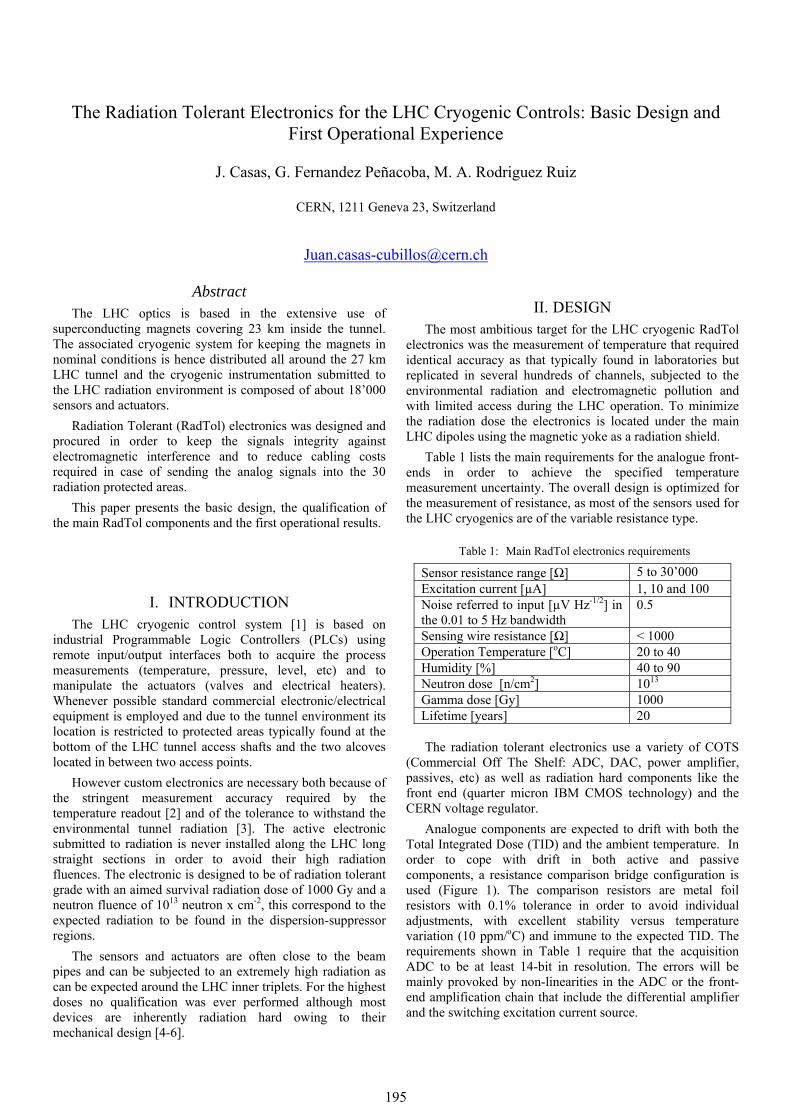
Analogue components are expected to drift with both the Total Integrated Dose (TID) and the ambient temperature. In order to cope with drift in both active and passive components, a resistance comparison bridge configuration is used (Figure 1). The comparison resistors are metal foil resistors with 0.1% tolerance in order to avoid individual adjustments, with excellent stability versus temperature variation (10 ppm/oC) and immune to the expected TID. The requirements shown in Table 1 require that the acquisition ADC to be at least 14-bit in resolution. The errors will be mainly provoked by non-linearities in the ADC or the front-end amplification chain that include the differential amplifier and the switching excitation current source.
195
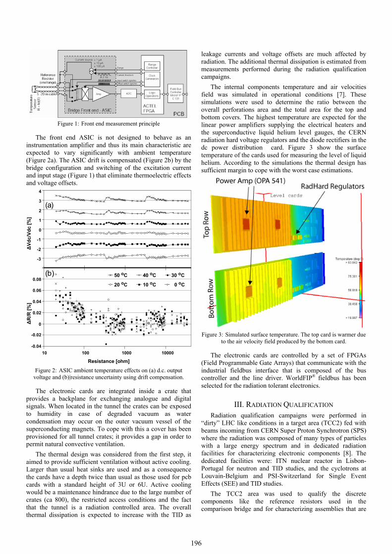
Figure 1: Front end measurement principle
The front end ASIC is not designed to behave as an instrumentation amplifier and thus its main characteristic are expected to vary significantly with ambient temperature (Figure 2a). The ASIC drift is compensated (Figure 2b) by the bridge configuration and switching of the excitation current and input stage (Figure 1) that eliminate thermoelectric effects and voltage offsets.
-3
-2
-1
0
1
2
3
4
0 oC10 oC20 oC
30 oC40 oC50 oC
ΔVd
c/Vd
c [%
]Δ
R/R
[%]
(a)
-0.04
-0.02
0
0.02
0.04
0.06
0.08
10 100 1000 10000
Resistance [ohm]
(b)
Figure 2: ASIC ambient temperature effects on (a) d.c. output
voltage and (b)|resistance uncertainty using drift compensation.
The electronic cards are integrated inside a crate that provides a backplane for exchanging analogue and digital signals. When located in the tunnel the crates can be exposed to humidity in case of degraded vacuum as water condensation may occur on the outer vacuum vessel of the superconducting magnets. To cope with this a cover has been provisioned for all tunnel crates; it provides a gap in order to permit natural convective ventilation.
The thermal design was considered from the first step, it aimed to provide sufficient ventilation without active cooling. Larger than usual heat sinks are used and as a consequence the cards have a depth twice than usual as those used for pcb cards with a standard height of 3U or 6U. Active cooling would be a maintenance hindrance due to the large number of crates (ca 800), the restricted access conditions and the fact that the tunnel is a radiation controlled area. The overall thermal dissipation is expected to increase with the TID as
leakage currents and voltage offsets are much affected by radiation. The additional thermal dissipation is estimated from measurements performed during the radiation qualification campaigns.
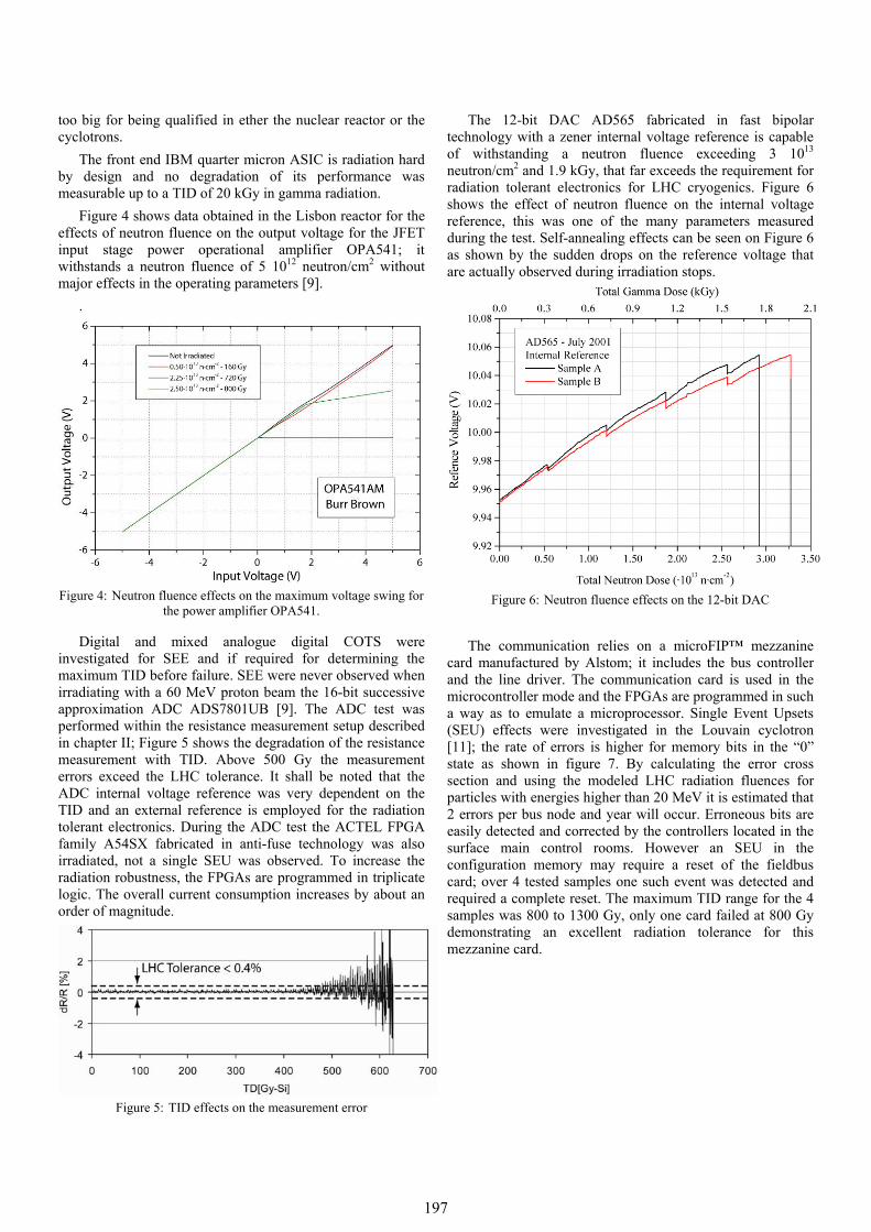
The internal components temperature and air velocities field was simulated in operational conditions [7]. These simulations were used to determine the ratio between the overall perforations area and the total area for the top and bottom covers. The highest temperature are expected for the linear power amplifiers supplying the electrical heaters and the superconductive liquid helium level gauges, the CERN radiation hard voltage regulators and the diode rectifiers in the dc power distribution card. Figure 3 show the surface temperature of the cards used for measuring the level of liquid helium. According to the simulations the thermal design has sufficient margin to cope with the worst case estimations.
Figure 3: Simulated surface temperature. The top card is warmer due
to the air velocity field produced by the bottom card.
The electronic cards are controlled by a set of FPGAs (Field Programmable Gate Arrays) that communicate with the industrial fieldbus interface that is composed of the bus controller and the line driver. WorldFIP® fieldbus has been selected for the radiation tolerant electronics.
III. RADIATION QUALIFICATION Radiation qualification campaigns were performed in
“dirty” LHC like conditions in a target area (TCC2) fed with beams incoming from CERN Super Proton Synchrotron (SPS) where the radiation was composed of many types of particles with a large energy spectrum and in dedicated radiation facilities for characterizing electronic components [8]. The dedicated facilities were: ITN nuclear reactor in Lisbon-Portugal for neutron and TID studies, and the cyclotrons at Louvain-Belgium and PSI-Switzerland for Single Event Effects (SEE) and TID studies.
The TCC2 area was used to qualify the discrete components like the reference resistors used in the comparison bridge and for characterizing assemblies that are
196
too big for being qualified in ether the nuclear reactor or the cyclotrons.
The front end IBM quarter micron ASIC is radiation hard by design and no degradation of its performance was measurable up to a TID of 20 kGy in gamma radiation.
Figure 4 shows data obtained in the Lisbon reactor for the effects of neutron fluence on the output voltage for the JFET input stage power operational amplifier OPA541; it withstands a neutron fluence of 5 1012 neutron/cm2 without major effects in the operating parameters [9].
.
Figure 4: Neutron fluence effects on the maximum voltage swing for
the power amplifier OPA541.
Digital and mixed analogue digital COTS were investigated for SEE and if required for determining the maximum TID before failure. SEE were never observed when irradiating with a 60 MeV proton beam the 16-bit successive approximation ADC ADS7801UB [9]. The ADC test was performed within the resistance measurement setup described in chapter II; Figure 5 shows the degradation of the resistance measurement with TID. Above 500 Gy the measurement errors exceed the LHC tolerance. It shall be noted that the ADC internal voltage reference was very dependent on the TID and an external reference is employed for the radiation tolerant electronics. During the ADC test the ACTEL FPGA family A54SX fabricated in anti-fuse technology was also irradiated, not a single SEU was observed. To increase the radiation robustness, the FPGAs are programmed in triplicate logic. The overall current consumption increases by about an order of magnitude.
Figure 5: TID effects on the measurement error
The 12-bit DAC AD565 fabricated in fast bipolar technology with a zener internal voltage reference is capable of withstanding a neutron fluence exceeding 3 1013 neutron/cm2 and 1.9 kGy, that far exceeds the requirement for radiation tolerant electronics for LHC cryogenics. Figure 6 shows the effect of neutron fluence on the internal voltage reference, this was one of the many parameters measured during the test. Self-annealing effects can be seen on Figure 6 as shown by the sudden drops on the reference voltage that are actually observed during irradiation stops.
Figure 6: Neutron fluence effects on the 12-bit DAC
The communication relies on a microFIP™ mezzanine card manufactured by Alstom; it includes the bus controller and the line driver. The communication card is used in the microcontroller mode and the FPGAs are programmed in such a way as to emulate a microprocessor. Single Event Upsets (SEU) effects were investigated in the Louvain cyclotron [11]; the rate of errors is higher for memory bits in the “0” state as shown in figure 7. By calculating the error cross section and using the modeled LHC radiation fluences for particles with energies higher than 20 MeV it is estimated that 2 errors per bus node and year will occur. Erroneous bits are easily detected and corrected by the controllers located in the surface main control rooms. However an SEU in the configuration memory may require a reset of the fieldbus card; over 4 tested samples one such event was detected and required a complete reset. The maximum TID range for the 4 samples was 800 to 1300 Gy, only one card failed at 800 Gy demonstrating an excellent radiation tolerance for this mezzanine card.
197
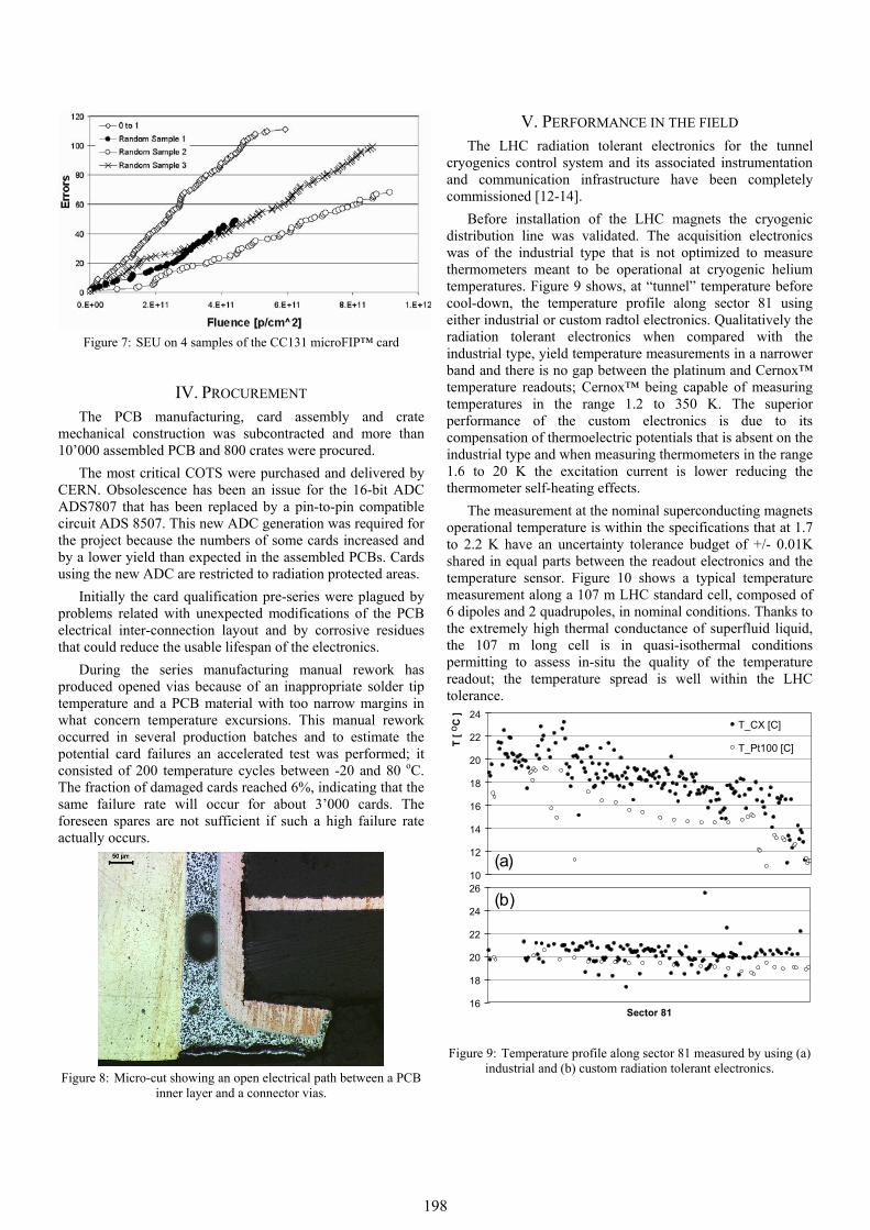
Figure 7: SEU on 4 samples of the CC131 microFIP™ card
IV. PROCUREMENT The PCB manufacturing, card assembly and crate
mechanical construction was subcontracted and more than 10’000 assembled PCB and 800 crates were procured.
The most critical COTS were purchased and delivered by CERN. Obsolescence has been an issue for the 16-bit ADC ADS7807 that has been replaced by a pin-to-pin compatible circuit ADS 8507. This new ADC generation was required for the project because the numbers of some cards increased and by a lower yield than expected in the assembled PCBs. Cards using the new ADC are restricted to radiation protected areas.
Initially the card qualification pre-series were plagued by problems related with unexpected modifications of the PCB electrical inter-connection layout and by corrosive residues that could reduce the usable lifespan of the electronics.
During the series manufacturing manual rework has produced opened vias because of an inappropriate solder tip temperature and a PCB material with too narrow margins in what concern temperature excursions. This manual rework occurred in several production batches and to estimate the potential card failures an accelerated test was performed; it consisted of 200 temperature cycles between -20 and 80 oC. The fraction of damaged cards reached 6%, indicating that the same failure rate will occur for about 3’000 cards. The foreseen spares are not sufficient if such a high failure rate actually occurs.
Figure 8: Micro-cut showing an open electrical path between a PCB
inner layer and a connector vias.
V. PERFORMANCE IN THE FIELD The LHC radiation tolerant electronics for the tunnel
cryogenics control system and its associated instrumentation and communication infrastructure have been completely commissioned [12-14].
Before installation of the LHC magnets the cryogenic distribution line was validated. The acquisition electronics was of the industrial type that is not optimized to measure thermometers meant to be operational at cryogenic helium temperatures. Figure 9 shows, at “tunnel” temperature before cool-down, the temperature profile along sector 81 using either industrial or custom radtol electronics. Qualitatively the radiation tolerant electronics when compared with the industrial type, yield temperature measurements in a narrower band and there is no gap between the platinum and Cernox™ temperature readouts; Cernox™ being capable of measuring temperatures in the range 1.2 to 350 K. The superior performance of the custom electronics is due to its compensation of thermoelectric potentials that is absent on the industrial type and when measuring thermometers in the range 1.6 to 20 K the excitation current is lower reducing the thermometer self-heating effects.
The measurement at the nominal superconducting magnets operational temperature is within the specifications that at 1.7 to 2.2 K have an uncertainty tolerance budget of +/- 0.01K shared in equal parts between the readout electronics and the temperature sensor. Figure 10 shows a typical temperature measurement along a 107 m LHC standard cell, composed of 6 dipoles and 2 quadrupoles, in nominal conditions. Thanks to the extremely high thermal conductance of superfluid liquid, the 107 m long cell is in quasi-isothermal conditions permitting to assess in-situ the quality of the temperature readout; the temperature spread is well within the LHC tolerance.
16
18
20
22
24
26
Sector 81
10
12
14
16
18
20
22
24
T [o
C ]
T_CX [C]
T_Pt100 [C]
(a)
(b)
Figure 9: Temperature profile along sector 81 measured by using (a) industrial and (b) custom radiation tolerant electronics.
198
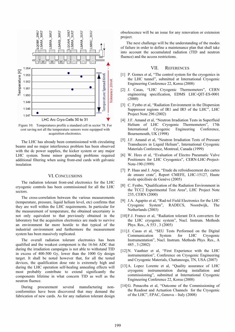
Figure 10: Temperatures profile a standard cell in sector 78. For
cost saving not all the temperature sensors were equipped with acquisition electronics.
The LHC has already been commissioned with circulating beams and no major interference problem has been observed with the dc power supplies, the kicker system or any major LHC system. Some minor grounding problems required additional filtering when using front-end cards with galvanic insulation
VI. CONCLUSIONS The radiation tolerant front-end electronics for the LHC
cryogenic controls has been commissioned for all the LHC sectors.
The cross-correlation between the various measurements (temperature, pressure, liquid helium level, etc) confirms that they are well within the LHC requirements. In particular for the measurement of temperature, the obtained uncertainty is not only equivalent to that previously obtained in the laboratory but the acquisition electronics are made to survive an environment far more hostile to that typical of the industrial environment and furthermore the measurement system has been massively replicated.
The overall radiation tolerant electronics has been qualified and the weakest component is the 16-bit ADC that during the irradiation campaigns is not able to withstand TID in excess of 400-500 Gy, lower than the 1000 Gy design target. It shall be noted however that, for all the tested devices, the qualification dose rate is extremely high and during the LHC operation self-healing annealing effects will most probably contribute to extend significantly the components lifetime in what concern TID as well as the neutron fluence.
During procurement several manufacturing non-conformities have been discovered that may demand the fabrication of new cards. As for any radiation tolerant design
obsolescence will be an issue for any renovation or extension project.
The next challenge will be the understanding of the modes of failure in order to define a maintenance plan that shall take into account the accumulated radiation (TID and neutron fluence) and the access restrictions.
VII. REFERENCES [1] P. Gomes et al, “The control system for the cryogenics in
the LHC tunnel”, submitted at International Cryogenic Engineering Conference 22, Korea (2008)
[2] J. Casas, “LHC Cryogenic Thermometers”, CERN engineering specification, EDMS LHC-QIT-ES-0001 (2000)
[3] C. Fynbo et al, “Radiation Environment in the Dispersion Suppressor regions of IR1 and IR5 of the LHC”, LHC Project Note 296 (2002)
[4] J.F. Amand et al, “Neutron Irradiation Tests in Superfluid Helium of LHC Cryogenic Thermometers”, 17th International Cryogenic Engineering Conference, Bournemouth, UK (1998)
[5] J.F. Amand et al, “Neutron Irradiation Tests of Pressure Transducers in Liquid Helium”, International Cryogenic Materials Conference, Montreal, Canada (1999)
[6] W. Hees et al, “Evaluation of Electro Pneumatic Valve Positioners for LHC Cryogenics”, CERN-LHC-Project-Note-190 (1999)
[7] P. Haas and J. Arpe, “Etude du refroidiseement des cartes de ensure crate”, Report CMEFE, LHC-15127, Haute école spécilisée de Genève (2005)
[8] C. Fynbo, "Qualification of the Radiation Environment in the TCC2 Experimental Test Area", LHC Project Note 235, CERN (2000)
[9] J.A. Agapito et al, “Rad-tol Field Electronics for the LHC Cryogenic System”, RADECS, Noordwijk, The Netherlands (2003)
[10] F.J. Franco et al, “Radiation tolerant D/A converters for the LHC cryogenic system”, Nucl. Instrum. Methods Phys. Res., A 553 , 3 (2005)
[11] J. Casas et al, “SEU Tests Performed on the Digital Communication System for LHC Cryogenic Instrumentation”, Nucl. Instrum. Methods Phys. Res., A 485 , 3 (2002)
[12] N. Vauthier et al, “First Experience with the LHC instrumentation”, Conference on Cryogenic Engineering and Cryogenic Materials, Chattanooga, TN, USA (2007)
[13] A. Lopez Lorente et al, “Quality assurance of LHC cryogenic instrumentation during installation and commissioning”, submitted at International Cryogenic Engineering Conference 22, Korea (2008)
[14] G. Penacoba et al, “Outcome of the Commissioning of the Readout and Actuation Channels for the Cryogenic of the LHC”, EPAC, Genova – Italy (2008)
199