THE PUSH-FIT SOLUTION FOR UNDERFLOOR HEATING€¦ · THE PUSH-FIT SOLUTION FOR UNDERFLOOR HEATING...
52
THE PUSH-FIT SOLUTION FOR UNDERFLOOR HEATING Installation and Technical Guide MARCH 2015 Includes this NEW addition:
Transcript of THE PUSH-FIT SOLUTION FOR UNDERFLOOR HEATING€¦ · THE PUSH-FIT SOLUTION FOR UNDERFLOOR HEATING...

THE PUSH-FIT SOLUTION FOR UNDERFLOOR HEATING
Installation and Technical Guide
MARCH 2015
Includes this NEW addition:

2
The John Guest Group has a long established reputation as a world leading manufacturer of push-fit fittings, tube and other fluid control products. A reputation built on producing consistently high quality products with an ongoing commitment to value engineering and product development.
Worldwide Connections
The strictest control is maintained by virtue of the fact that design and manufacture is carried out in modern purpose built manufacturing centres in west London and at Maidenhead in Berkshire.
Maintaining control over the whole process from initial tool design and tool making through to final assembly and testing ensuring that only products of the highest quality are produced.
The company believe it is this commitment to quality that has led to it receiving prestigious awards from many of the world’s leading testing and approvals organisations.
John Guest is a preferred supplier to many international companies.
A commitment to quality is at the heart of the John Guest Philosophy
Quality Manufacture
Speedfit PEX Fittings and Barrier Pipe.
K24076, K24077 and K24078
British Gas Service
BS7291No. KM39767

3
Members of the Technical Support Team are available to help you get the best from your Speedfit Underfloor Heating System.
To obtain an estimate send us a plan of the area where underfloor heating is required, indicating the preferred location of the manifold and intended floor construction.
An estimate will be prepared and when approved and an order placed, the Speedfit CAD
Design Service will provide a detailed drawing showing pipe layout, flow rates, suggested zone temperatures and advice on commissioning.
A member of our national team of Technical Support Engineers will be available to offer on-site support during the installation process.
Technical Help Desk: 01895 425333 | [email protected]
The JG Speedfit Technical Advisory Service is available to assist and advise on all aspects of using the Speedfit System. The service is available between 8.00am and 5.00pm Monday to Friday.
Design Service and Technical SupportCAD Design Service
The Speedfit System for Underfloor Heating has been designed to be as quick and easy as possible to install with component parts manufactured under an ISO9001 Quality Management System.
The System has water pumped from a boiler or other heat source to a pump pack where it is mixed to approximately
50ºC then distributed via a manifold to heating circuits made using Speedfit Barrier Pipe. The temperature and volume of water is altered to maintain the requirements of the system.
The pipe is laid in concrete or suspended just below the surface of timber flooring.
A wide range of electrical components means the system can have as much control as required.
www.speedfitUFH.co.uk
4
CO
NTE
NTS
CONTENTS:UNDERFLOOR HEATING
PREPARATION CONSIDERATIONS
PIPE INSTALLATION
JG UFH MANIFOLD & PUMP PACK INSTALLATION
p6-9
p10-19
p20-33
p34
HEATING CONTROLS
p36-41
5www.speedfitUFH.co.uk
CO
NTE
NTS
COMMISSIONING CHECKLIST
FREQUENTLY ASKED QUESTIONS& TROUBLESHOOTING
FILLING & TESTING
p42-43
p46-47
p48-49
START-UP & COMMISSIONING
p44-45
33
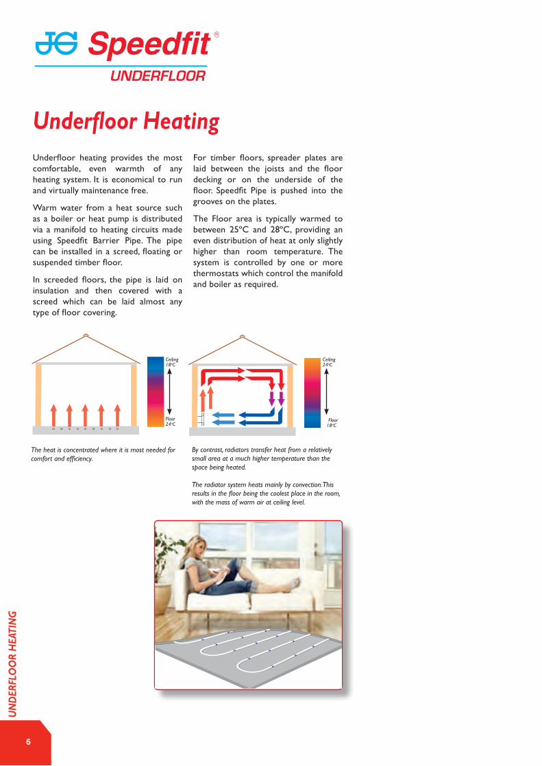
Underfloor heating provides the most comfortable, even warmth of any heating system. It is economical to run and virtually maintenance free.
Warm water from a heat source such as a boiler or heat pump is distributed via a manifold to heating circuits made using Speedfit Barrier Pipe. The pipe can be installed in a screed, floating or suspended timber floor.
In screeded floors, the pipe is laid on insulation and then covered with a screed which can be laid almost any type of floor covering.
For timber floors, spreader plates are laid between the joists and the floor decking or on the underside of the floor. Speedfit Pipe is pushed into the grooves on the plates.
The Floor area is typically warmed to between 25ºC and 28ºC, providing an even distribution of heat at only slightly higher than room temperature. The system is controlled by one or more thermostats which control the manifold and boiler as required.
The heat is concentrated where it is most needed for comfort and efficiency.
By contrast, radiators transfer heat from a relatively small area at a much higher temperature than the space being heated.
The radiator system heats mainly by convection. This results in the floor being the coolest place in the room, with the mass of warm air at ceiling level.
Ceiling18oC
Ceiling24oC
Floor24oC
Floor18oC
6
Underfloor Heating
UN
DER
FLO
OR
HEA
TIN
G
7www.speedfitUFH.co.uk
The Speedfit Underfloor Heating System offers many benefits to the consumer. These include:
Efficiency SavingsUnderfloor Heating Systems are designed to operate at lower temperatures than radiator systems, making them especially suitable for condensing boilers and heat pumps. This results in reduced energy consumption and lower heating costs for the building.
InstallationIt is simple to install, requiring the minimum of installation effort and little maintenance.
ComfortThe system uses mainly radiant heat, the most comfortable form of heating, giving an even distribution of warmth over the whole room.
Space The system is unobtrusive and space saving which means every square metre of floor and wall space can be utilised giving freedom of interior design.
NoiseCompared to radiator systems the system is virtually silent running.
HealthDust is minimised reducing the problem of house dust mites. Reduced numbers of hot surfaces and sharp edges minimise risk of burns or injury.
ControlUnderfloor heating is easy to control and unlike conventional radiator systems, makes use of multi-zoning so each room benefits from individual time and temperature control resulting in a more flexible heating system with lower running costs.
Environment Underfloor heating is suitable for use with the most energy efficient and environmentally friendly heating systems including condensing boilers, solar power and heat pumps.
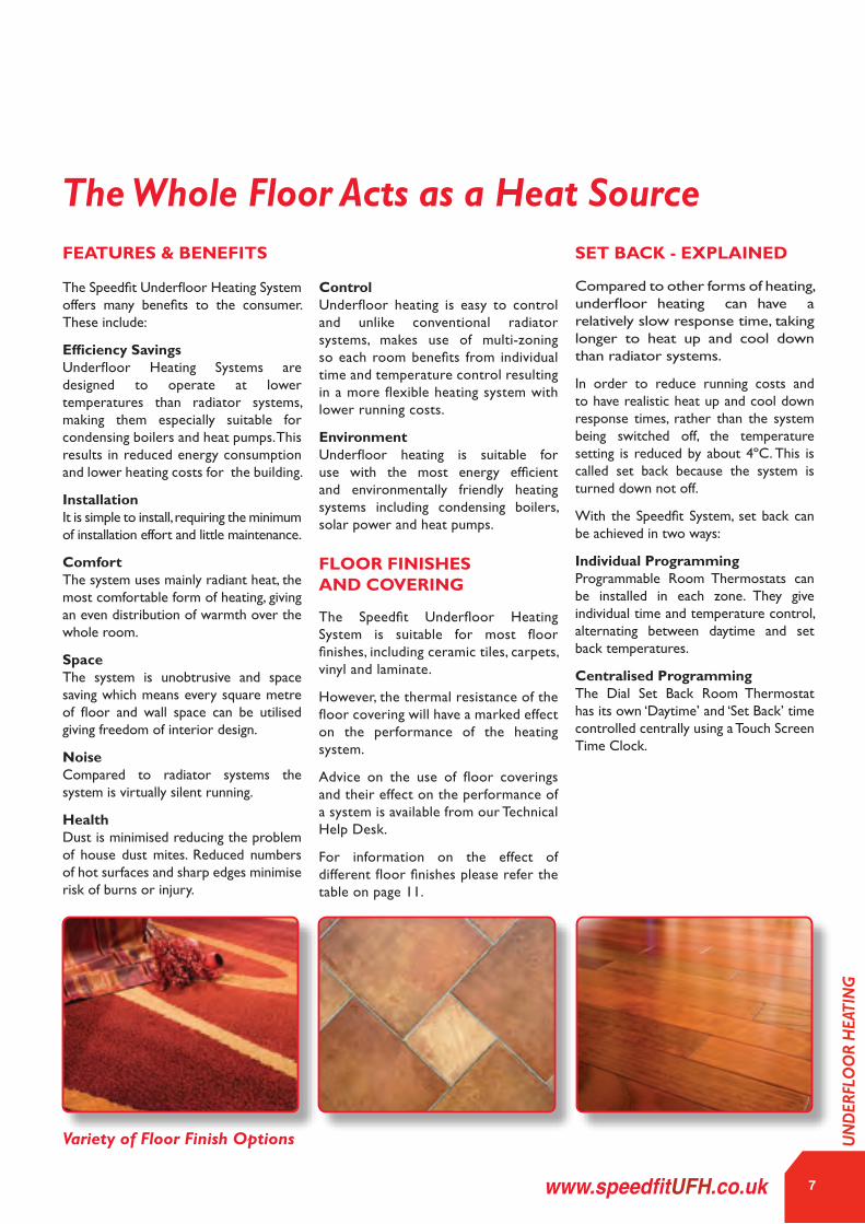
The Speedfit Underfloor Heating System is suitable for most floor finishes, including ceramic tiles, carpets, vinyl and laminate.
However, the thermal resistance of the floor covering will have a marked effect on the performance of the heating system.
Advice on the use of floor coverings and their effect on the performance of a system is available from our Technical Help Desk.
For information on the effect of different floor finishes please refer the table on page 11.
FEATURES & BENEFITS
FLOOR FINISHES AND COVERING
Variety of Floor Finish Options
SET BACK - EXPLAINED
Compared to other forms of heating, underfloor heating can have a relatively slow response time, taking longer to heat up and cool down than radiator systems.
In order to reduce running costs and to have realistic heat up and cool down response times, rather than the system being switched off, the temperature setting is reduced by about 4ºC. This is called set back because the system is turned down not off.
With the Speedfit System, set back can be achieved in two ways:
Individual ProgrammingProgrammable Room Thermostats can be installed in each zone. They give individual time and temperature control, alternating between daytime and set back temperatures.
Centralised ProgrammingThe Dial Set Back Room Thermostat has its own ‘Daytime’ and ‘Set Back’ time controlled centrally using a Touch Screen Time Clock.
The Whole Floor Acts as a Heat Source
UN
DER
FLO
OR
HEA
TIN
G

As the chart above shows, people are more comfortable when their feet are in a warm area and their head is slightly cooler.
A system using radiators will have colder air at the bottom of a room which places your feet in the wrong place for comfortable living. This is because cold air is more dense (heavy) and it is pulled downwards by gravity.
In contrast, Underfloor Heating heats the whole floor. This means that the warmest space is the area nearest the floor, which matches the preferred heat profile.
In practice, normal comfort can be achieved at a lower air temperature than with conventional radiators because underfloor heating systems heat mainly by radiated energy, just like the energy from the sun.
Radiant energy is emitted by the floor giving an even distribution of heat. This means no cold spots, hot ceilings or cold feet.
In its simplest form, Underfloor Heating is pipes in the floor with blended water passing through them. The Speedfit Underfloor Heating System receives water from a heat source such as a boiler or heatpump. High temperature water from a source like a conventional boiler is then blended to reduce the flow temperature. It is then distributed via a manifold to heating circuits made up of Speedfit Barrier Pipe. Low temperature water, such as from a Heat Pump, may not need to be blended down.
The pipe is laid in concrete or suspended under timber flooring. Effectively, the floor is turned into a large, low surface temperature heat emitter which is economical to run and provides a similar level of comfort, at 20°C, to a convection system providing an air temperature of 21° - 22°C.
Heating times and comfort temperatures are controlled by individual thermostats to enable the user to maximise comfort, flexibility and reduce running costs.
8
Underfloor Heating
Theoretically ideal heating
24º 24º 18º 16º
20º 20º 20º 20º
16º 16º 24º 24º
1.70
2.70
Underfloor Heating
Radiator heating on inside wall
Warm air heating
Eye level
UN
DER
FLO
OR
HEA
TIN
G

9www.speedfitUFH.co.uk
PREP
ARAT
ION
CO
NSI
DER
ATIO
NS

10
PLANNING AND ORGANISING YOUR PROJECT
The design of an underfloor heating system has a direct link to its output and efficiency. Careful consideration should be given to underfloor heating at an early stage in any project as the system needs to be integrated with construction and building programmes. The key to a successful installation is to invest time in planning the system. If your system has already been designed and you are ready to start your installation, it is useful to ensure you have covered all the points below. For example, the builder or architect needs to ensure that sufficient floor depth is available and that suitable insulation is specified. An increase in floor height at a late stage can have implications to other areas of the construction.
THINGS TO REMEMBER • Insulation depth as required by design or building regulations and to ensure that any downward heat loss does not exceed 10 watts per m2 in accordance with BSEN1264.
• The overall quality and thickness of a sand and cement screed should meet the requirements of BS8204-1.
ORGANISING YOUR UNDERFLOOR HEATING PROJECT
CUSTOMER / CLIENT • Supply up to date plans and relevant information to system designer.
SYSTEM DESIGNER • Prepare design calculations, specifications, material schedules and layout drawings to BSEN1264.
INSTALLER • Ensure the design drawings and specifications are followed and installed correctly.
GATHERING ALL THE INFORMATION
The following information will be required to complete a system design.
• Full building plans including sections and elevations. • Calculation of heat loss and heat requirement. • Floor construction and insulation to be used. • Preferred manifold locations. • Heat source to be used.
SPEEDFIT SERVICE Planning your system does not need to be daunting. Speedfit offer a comprehensive design and technical support service. Our National team of engineers and designers will work closely with our customers and guide them through the whole process. A full support package is offered at every stage from the initial enquiry, through the design process, procurement of materials and followed up with on-site visits to offer installer advice.
Some buildings need more heat than others. As building methods have progressed over the years and insulation materials have improved, less and less energy is needed to heat them up. When using radiators in an old building it is easy to increase the size of the radiator for poorly insulated rooms. This is not possible with Underfloor Heating as the floor size is fixed. While Underfloor Heating can easily heat the majority of homes, care needs to be taken to match the output of the Underfloor Heating to the needs of a room.
When installing the Underfloor Heating system, consideration should be paid to areas of high heat loss which may affect performance of the system.
These include :- • Conservatories • Un-insulated / poorly insulated walls. • Single glazed or draughty windows. • Open fireplace. • Un-insulated lofts and floors. • Areas with a high proportion of glazing. • Room with a high perimeter wall to floor ratio.
In these situations, the thermal envelope of the buildings should be brought up to current building insulation standards.
The table opposite helps to highlight the relative heat output of a varity of floor finishes when used with different installation methods.
Preparation Considerations
PREP
ARAT
ION
CO
NSI
DER
ATIO
NS
HEAT LOSS & HEAT OUTPUT FROM AN UNDERFLOOR HEATING SYSTEM
11www.speedfitUFH.co.uk
PREP
ARAT
ION
CO
NSI
DER
ATIO
NS
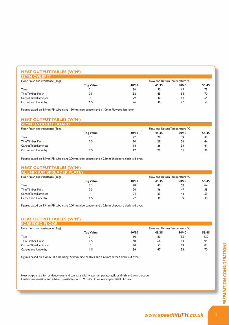
HEAT OUTPUT TABLES (W/M2)25MM OVERFITFloor finish and resistance (Tog) Flow and Return Temperature ºC Tog Value 40/30 45/35 50/40 55/45Tiles 0.1 36 50 65 78Thin Timber Finish 0.5 32 45 58 70Carpet Tiles/Laminate 1 29 40 52 64Carpet and Underlay 1.5 26 36 47 58
Figures based on 15mm PB tube using 150mm pipe centres and a 10mm Plywood laid over.
HEAT OUTPUT TABLES (W/M2)50MM UNDERFIT BOARDFloor finish and resistance (Tog) Flow and Return Temperature ºC Tog Value 40/30 45/35 50/40 55/45Tiles 0.1 22 20 39 48Thin Timber Finish 0.5 20 28 36 44Carpet Tiles/Laminate 1 18 26 33 41Carpet and Underlay 1.5 17 22 31 38
Figures based on 15mm PB tube using 200mm pipe centres and a 22mm chipboard deck laid over.
HEAT OUTPUT TABLES (W/M2)ALUMINIUM SPREADER PLATESFloor finish and resistance (Tog) Flow and Return Temperature ºC Tog Value 40/30 45/35 50/40 55/45Tiles 0.1 28 40 52 64Thin Timber Finish 0.5 26 36 47 58Carpet Tiles/Laminate 1 24 33 43 53Carpet and Underlay 1.5 22 31 39 48
Figures based on 15mm PB tube using 200mm pipe centres and a 22mm chipboard deck laid over.
HEAT OUTPUT TABLES (W/M2)SCREEDED FLOORFloor finish and resistance (Tog) Flow and Return Temperature ºC Tog Value 40/30 45/35 50/40 55/45Tiles 0.1 60 80 95 120Thin Timber Finish 0.5 48 66 83 95Carpet Tiles/Laminate 1 40 53 69 83Carpet and Underlay 1.5 34 47 58 70
Figures based on 15mm PB tube using 200mm pipe centres and a 65mm screed deck laid over.
Heat outputs are for guidance only and can vary with water temperature, floor finish and construction. Further information and advice is available on 01895 425333 or www.speedfitUFH.co.uk

12
If you are new to installing Underfloor Heating, you need to understand that the floor construction will normally determine the way in which the system is installed. There are several options available to suit both new build and renovation projects. Before commencing work, it is important to take some time to familiarise yourself with the steps needed for the floor construction you are working with.
Solid floors already have a requirement for insulation and screed. The pipework is fitted to the insulation using clips, staples, or using a number of other alternative methods. Once the pipework is in place and has been tested for leaks, the screed is laid on
top and left to cure. When the screed has had sufficient time to cure the heating is turned on, the screed is heated and this in turn heats the room. Solid screeded floors tend to give the highest heat output.
Suspended Floors are different as there is no screed to absorb the heat from the pipes and transfer this energy to the floor. There are a number of things to consider, such as, holding the pipes in place, transferring the energy from the pipes to the floor and insulating below the pipework in order to force the heat up into the floor covering. Suspended flooring usually needs a higher flow temperature from the boiler or heat
source. Due to the nature of the floor construction (e.g. floor boards, underlay and carpets) the resistance to heat transfer is higher.
Overfit - Typically this method is used in refurbishment projects where floor depths are a consideration. Thin pre-grooved insulation boards are laid over the floor structure to enable a low height installation.
Refer to pages 20 to 33 for more information on solid/supended/overfit systems.
With the drive to promote the use of renewable-energy sources in new buildings and refurbishment projects, the use of Heat Pumps with Underfloor Heating has clear benefits. Heat pumps generally supply a maximum water flow temperature of 35-45°C, which is an ideal temperature for Underfloor Heating. Using these lower temperatures increases the COP (Coefficient Of Performance) of the heat pump.
Because of the lower temperatures there is less energy per metre of pipe, therefore there may need to be an increase to the amount of pipe used in a project. This is typically achieved by using pipework at closer spacings which will
depend on the floor construction. With careful design of the Underfloor Heating system when combined with lower resistance floor finishes, efficiency can be increased resulting in lower emissions and lower fuel bills.
Converseley, poor levels of building insulation when combined with high resistance floor coverings may require a higher temperature output from the heat pump which may lead to poor performance or unacceptable response times.
For further advice & information please contact our technical support line 01895 425333.
Preparation ConsiderationsDETERMINE THE FLOOR CONSTRUCTION AND INSTALLATION METHOD
HEAT SOURCE & INTEGRATION OF NEW TECHNOLOGIES
PREP
ARAT
ION
CO
NSI
DER
ATIO
NS

13www.speedfitUFH.co.uk
UNDERFLOOR HEATING MANIFOLD Manifolds distribute the heating water to each heating circuit in the system and allows the isolation and flow rate setting of each circuit. A unique feature to JG systems is that connections to the heating pipes are Speedfit push-fit, offering much reduced installation times. All manifolds are pre-fitted with brackets, vibration isolation mounts, and an automatic air vent. Flow rate indicators include the means to adjust flow rate and isolate the circuit. The Manifold can be assembled to suit left-hand or right-hand supply depending upon project type.
CONTROL PACK Connected to the manifold, this unit regulates the flow temperature and pumps the water to each circuit. When using a low temperature heat source or a dedicated boiler, a control unit may not be required. These compact, modular control packs for underfloor heating systems up to 14kW, are designed to be lightweight in order to connect directly to Speedfit manifolds without the need for extra brackets or support. The nickel plated material matches the stainless steel Speedfit manifold. The Control Pack consists of a mixing valve, circulating pump, return elbow, manifold adaptor and all necessary seals.
SPEEDFIT LAYFLAT® BARRIER PIPE Manufactured to the highest of standards, our pipe is available in either PEX or JG Layflat® Polybutylene. Speedfit Pipe has an inner barrier to prevent the ingress of oxygen molecules. It is manufactured and Kitemarked to British Standard BS7291: Parts 1, 2 & 3: Class S. JG Layflat® Pipe is easy to handle when removed from the coil and very flexible making it especially suitable for underfloor heating installations. For screed systems, the pipe is attached directly to insulation with staples, floor clips or mounting rails. Spreader Plates are available for timber flooring using either traditional joists or engineered I-Beam Joists.
PIPE FIXING SYSTEM A pipe fixing method will be needed in order to complete the necessary pipe circuits. A host of different pipe fixing systems are available depending on project type such as whether the installation is being completed on a solid or timber floor. For solid floor projects that will involve the use of screed, it is also important to choose appropriate insulation that can be fitted to a flat sub-base. For more information on the different Speedfit fixing systems, please go to our pipe installation section on pages 20 to 33.
HEATING CONTROL SYSTEM An appropriate allocation of heating thermostats will be required on all underfloor heating systems. JG Speedfit offer a variety of systems options including 230v standard and wireless along with internet enabled wireless. Also includes wireless thermostatic radiator control. For more information on the different Speedfit Thermostat Control Systems please go to page 36.
PRODUCT CHECKLIST
PREP
ARAT
ION
CO
NSI
DER
ATIO
NS

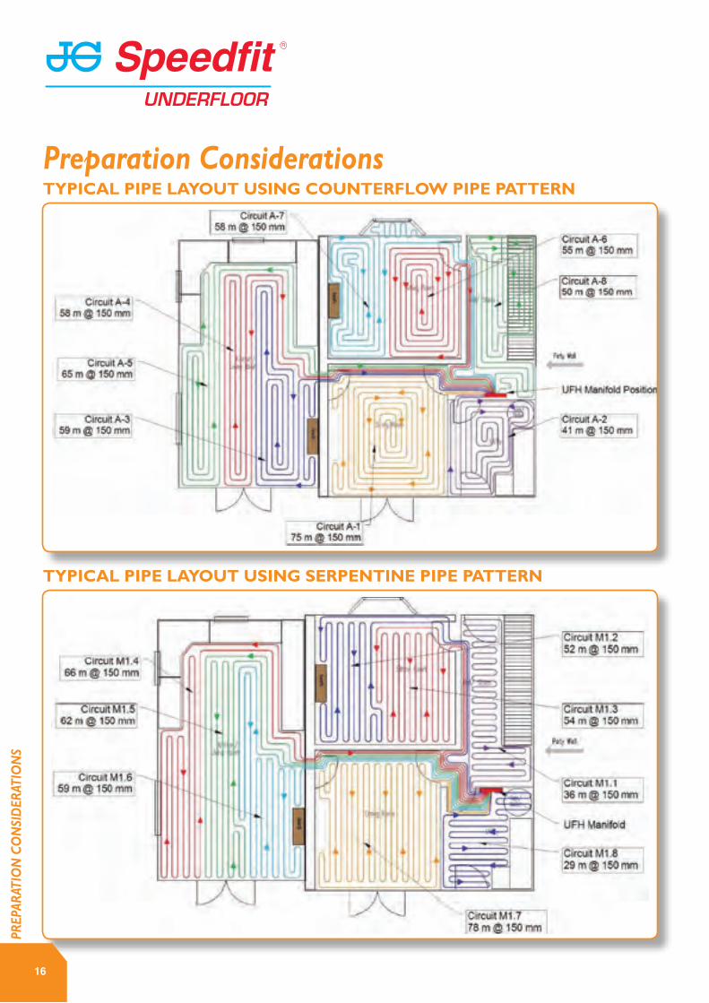
A pipe layout plan is supplied with each project upon request. The drawing shows all the important information to correctly install the Underfloor Heating pipework and Manifolds. There are also details of flow rates, pipe spacing and routing of pipe from the manifold to each heated zone.
Before starting the installation, it is important to check that the drawing matches the site conditions as any
deviation could result in the need to revise the plans and potentially the underfloor heating materials required.
The manifold location and position of permanent fixtures such as kitchen units, cupboards and sanitary fittings should also be checked prior to installation to ensure they do not interfere with the pipe routing.
Thermostats should be cited in accordance with the manufacturers
recommendation and site requirements.
There are alternative pipe patterns to those shown here, however, the main two that are used are Serpentine and Counterflow patterns.
READING A CAD DRAWING
Preparation Considerations
14
PREP
ARAT
ION
CO
NSI
DER
ATIO
NS
TYPICAL PIPE LAYOUTS
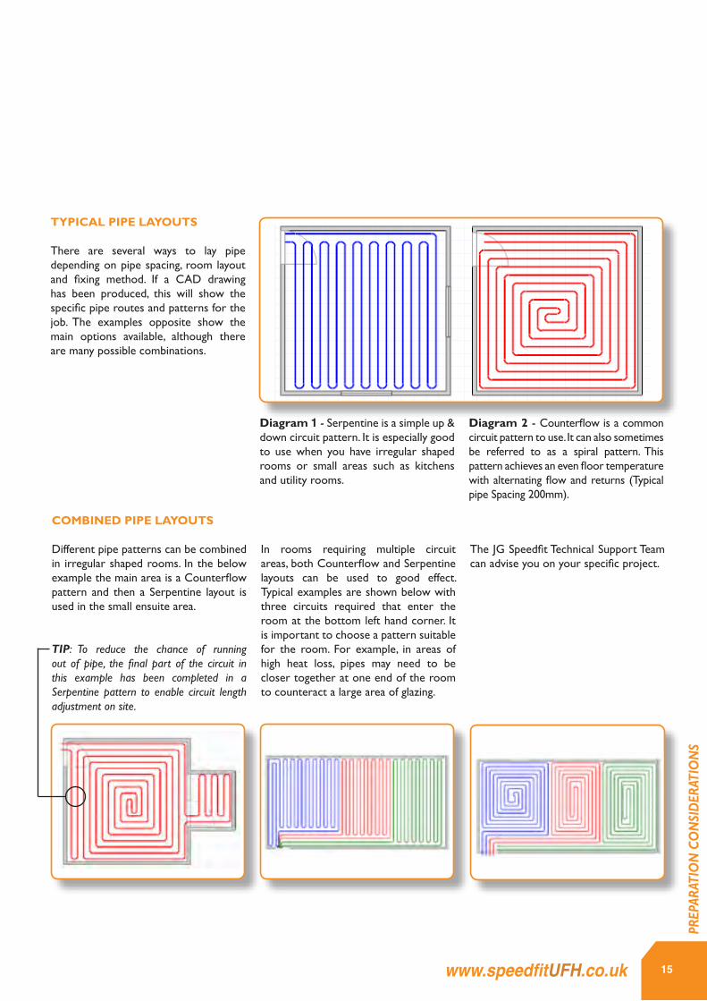
There are several ways to lay pipe depending on pipe spacing, room layout and fixing method. If a CAD drawing has been produced, this will show the specific pipe routes and patterns for the job. The examples opposite show the main options available, although there are many possible combinations.
Diagram 1 - Serpentine is a simple up & down circuit pattern. It is especially good to use when you have irregular shaped rooms or small areas such as kitchens and utility rooms.
Diagram 2 - Counterflow is a common circuit pattern to use. It can also sometimes be referred to as a spiral pattern. This pattern achieves an even floor temperature with alternating flow and returns (Typical pipe Spacing 200mm).
COMBINED PIPE LAYOUTS
Different pipe patterns can be combined in irregular shaped rooms. In the below example the main area is a Counterflow pattern and then a Serpentine layout is used in the small ensuite area.
TIP: To reduce the chance of running out of pipe, the final part of the circuit in this example has been completed in a Serpentine pattern to enable circuit length adjustment on site.
In rooms requiring multiple circuit areas, both Counterflow and Serpentine layouts can be used to good effect. Typical examples are shown below with three circuits required that enter the room at the bottom left hand corner. It is important to choose a pattern suitable for the room. For example, in areas of high heat loss, pipes may need to be closer together at one end of the room to counteract a large area of glazing.
The JG Speedfit Technical Support Team can advise you on your specific project.
Typical Pipe Layouts There are several ways to lay pipe out depending on pipe spacing, room layout and xing method. If a CAD drawing has been produced, this will show the specic pipe routes and pa�erns for the job, however the examples below show the main op�ons available although there are many combina�ons possible.
TIP : to reduce the chance of running out pipe the nal part of the circuit, in this example has been completed in a serpen�ne pa�ern to enable easy adjustment on site.
Diagram 2— Counter Flow a common circuit pa�ern to use, it can some�mes be referred to as a spiral pa�ern. This pa�ern achieves an even oor temperature with alterna�ng ow and returns. (Typical pipe Spacing 200mm)
Diagram 1— Serpen�ne is a simple up & down circuit pa�ern. It is espe‐cially good to use when you have irregular shaped rooms or small areas such as kitchens and u�lity rooms. This pa�ern is also used for the
Different pipe pa�erns can be combined in irregular shaped rooms. In this example the main area is a counterow pa�ern and then ser‐pen�ne is used in the small en‐suite area.
In rooms requiring mul�ple circuits areas, both counterow and serpen�ne can be used to good effect. A typical example is shown here with 3 circuits required which enter to room at the bo�om le� hand corner. It is important to choose a pa�ern suitable for the room. For example in areas of high heatloss pipes may need to be closer together at one end of the room to counteract a large area of glazing.
The JG Speedt Technical Support Team can advise you on your specic project
15www.speedfitUFH.co.uk
PREP
ARAT
ION
CO
NSI
DER
ATIO
NS
Typical Pipe Layouts There are several ways to lay pipe out depending on pipe spacing, room layout and xing method. If a CAD drawing has been produced, this will show the specic pipe routes and pa�erns for the job, however the examples below show the main op�ons available although there are many combina�ons possible.
TIP : to reduce the chance of running out pipe the nal part of the circuit, in this example has been completed in a serpen�ne pa�ern to enable easy adjustment on site.
Diagram 2— Counter Flow a common circuit pa�ern to use, it can some�mes be referred to as a spiral pa�ern. This pa�ern achieves an even oor temperature with alterna�ng ow and returns. (Typical pipe Spacing 200mm)
Diagram 1— Serpen�ne is a simple up & down circuit pa�ern. It is espe‐cially good to use when you have irregular shaped rooms or small areas such as kitchens and u�lity rooms. This pa�ern is also used for the
Different pipe pa�erns can be combined in irregular shaped rooms. In this example the main area is a counterow pa�ern and then ser‐pen�ne is used in the small en‐suite area.
In rooms requiring mul�ple circuits areas, both counterow and serpen�ne can be used to good effect. A typical example is shown here with 3 circuits required which enter to room at the bo�om le� hand corner. It is important to choose a pa�ern suitable for the room. For example in areas of high heatloss pipes may need to be closer together at one end of the room to counteract a large area of glazing.
The JG Speedt Technical Support Team can advise you on your specic project
16
PREP
ARAT
ION
CO
NSI
DER
ATIO
NS
TYPICAL PIPE LAYOUT USING COUNTERFLOW PIPE PATTERN
TYPICAL PIPE LAYOUT USING SERPENTINE PIPE PATTERN
Preparation Considerations
17www.speedfitUFH.co.uk
PREP
ARAT
ION
CO
NSI
DER
ATIO
NS
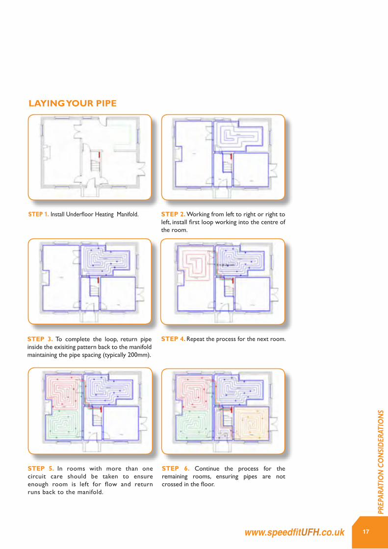
LAYING YOUR PIPE
STEP 1. Install Underfloor Heating Manifold.
STEP 4. Repeat the process for the next room.STEP 3. To complete the loop, return pipe inside the exisiting pattern back to the manifold maintaining the pipe spacing (typically 200mm).
STEP 6. Continue the process for the remaining rooms, ensuring pipes are not crossed in the floor.
STEP 2. Working from left to right or right to left, install first loop working into the centre of the room.
STEP 5. In rooms with more than one circuit care should be taken to ensure enough room is left for flow and return runs back to the manifold.
1 . Install UFH manifold
2 . Working from le� to right or right to le� install rst loop working into the centre of the room.
3 . To complete the loop , return inside the pipe back to the mani‐fold maintaining the pipe spacing (typically 200mm)
4 . Repeat the process for the next room.
5 . In rooms with more than one circuit care should be taken to ensure enough room is le� for ow and returns back to the manifold.
6 . Con�nue the process for the re‐maining rooms, ensuring pipes are not crossed in the oor.
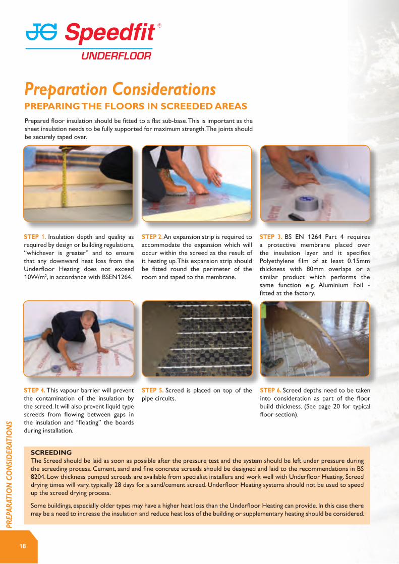
STEP 1. Insulation depth and quality as required by design or building regulations, “whichever is greater” and to ensure that any downward heat loss from the Underfloor Heating does not exceed 10W/m2, in accordance with BSEN1264.
STEP 4. This vapour barrier will prevent the contamination of the insulation by the screed. It will also prevent liquid type screeds from flowing between gaps in the insulation and “floating” the boards during installation.
STEP 3. BS EN 1264 Part 4 requires a protective membrane placed over the insulation layer and it specifies Polyethylene film of at least 0.15mm thickness with 80mm overlaps or a similar product which performs the same function e.g. Aluminium Foil - fitted at the factory.
STEP 2. An expansion strip is required to accommodate the expansion which will occur within the screed as the result of it heating up. This expansion strip should be fitted round the perimeter of the room and taped to the membrane.
STEP 5. Screed is placed on top of the pipe circuits.
STEP 6. Screed depths need to be taken into consideration as part of the floor build thickness. (See page 20 for typical floor section).
Prepared floor insulation should be fitted to a flat sub-base. This is important as the sheet insulation needs to be fully supported for maximum strength. The joints should be securely taped over.
SCREEDING The Screed should be laid as soon as possible after the pressure test and the system should be left under pressure during the screeding process. Cement, sand and fine concrete screeds should be designed and laid to the recommendations in BS 8204. Low thickness pumped screeds are available from specialist installers and work well with Underfloor Heating. Screed drying times will vary, typically 28 days for a sand/cement screed. Underfloor Heating systems should not be used to speed up the screed drying process.
Some buildings, especially older types may have a higher heat loss than the Underfloor Heating can provide. In this case there may be a need to increase the insulation and reduce heat loss of the building or supplementary heating should be considered.
18
PREPARING THE FLOORS IN SCREEDED AREAS
Preparation Considerations
PREP
ARAT
ION
CO
NSI
DER
ATIO
NS

19www.speedfitUFH.co.uk
PREP
ARAT
ION
CO
NSI
DER
ATIO
NS

THE UFH STAPLE SYSTEM
20
Pipe Installation
PIPE
INST
ALLA
TIO
N
Part No. Description
JGUFHEDGE 25 METRE ROLL
EDGE STRIP
Part No. Description
JGUFHGUN STAPLE GUN
JGUFHSTAPLE PIPE STAPLES
PIPE STAPLES
PRODUCTS ESSENTIAL FOR THIS INSTALLATION
Part No. Description Size
15BPB-50C BARRIER PIPE 15MM X 50M
15BPB-100C BARRIER PIPE 15MM X 100M
15BPB-120C BARRIER PIPE 15MM X 120M
15BPB-150C BARRIER PIPE 15MM X 150M
JG LAYFLAT® POLYBUTYLENE BARRIER PIPE
THINGS TO REMEMBER • Insulation depth as required by design or building regulations to ensure that any downward heat loss does not exceed 10 watts per m/2 in accordance with BSEN1264.
• The overall quality and thickness of a sand and cement screed should meet the requirements of BS8204-1.
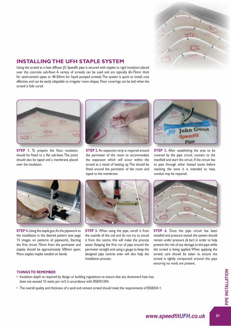
STEP 1. To prepare the floor, insulation should be fitted to a flat sub-base. The joints should also be taped and a membrane placed over the insulation.
STEP 4. Using the staple gun, fix the pipework to the installation in the desired pattern (see page 15 images on patterns of pipework). Starting the first circuit 75mm from the perimeter and staples should be approximately 500mm apart. More staples maybe needed on bends.
STEP 3. After establishing the area to be covered by the pipe circuit, connect to the manifold and start the circuit. If the circuit has to pass through other heated zones before reaching the zone it is intended to heat, conduit may be required.
STEP 6. Once the pipe circuit has been installed and pressure tested, the system should remain under pressure (6 bar) in order to help prevent the risk of any damage to the pipe while the screed is being applied. When applying the screed, care should be taken to ensure the screed is tightly compacted around the pipe ensuring no voids are present.
STEP 2. An expansion strip is required around the perimeter of the room to accommodate the expansion which will occur within the screed as a result of heating up. This should be fitted around the perimeter of the room and taped to the membrane.
STEP 5. When using the pipe, unroll it from the outside of the coil and do not try to uncoil it from the centre, this will make the process easier. Keeping the first run of pipe around the perimeter straight and using a gauge to keep the designed pipe centres even will also help the installation process.
Using the screed as a heat diffuser, JG Speedfit pipe is secured with staples to rigid insulation placed over the concrete sub-floor. A variety of screeds can be used and are typically 65-75mm thick for sand-cement types or 40-50mm for liquid pumped screeds. The system is quick to install, cost effective, and can be easily adaptable to irregular room shapes. Floor coverings can be laid when the screed is fully cured.
INSTALLING THE UFH STAPLE SYSTEM
21www.speedfitUFH.co.uk
PIPE
INST
ALLA
TIO
N

THE MOUNTING RAIL
PRODUCTS ESSENTIAL FOR THIS INSTALLATION
Pipe Installation
22
PIPE
INST
ALLA
TIO
N
Part No. Description
JGUFHEDGE 25 METRE ROLL
EDGE STRIP
Part No. Description
JGUFHRAIL 2 METRE LONG
JGUFHPIN RAIL PINS FOR ABOVE
MOUNTING RAIL
Part No. Description Size
15BPB-50C BARRIER PIPE 15MM X 50M
15BPB-100C BARRIER PIPE 15MM X 100M
15BPB-120C BARRIER PIPE 15MM X 120M
15BPB-150C BARRIER PIPE 15MM X 150M
JG LAYFLAT® POLYBUTYLENE BARRIER PIPE
THINGS TO REMEMBER • 1.5 to 2 linear metres of mounting rail per sq/m of floor area. 1 pack per 20sq/m.• Maximum circuit length 100m of 15mm pipe.• Maximum coverage Approx. 100m centres 11 sq/m 200mm centres 20sq/m.• Maximum heat output for 200mm centres = 100Wsq/m.• Recommended design flow temperature 50oC.• Insulation depth as required by design or building regulations to ensure that any downward. heat loss does not exceed 10 watts per m/2 in accordance with BSEN1264.
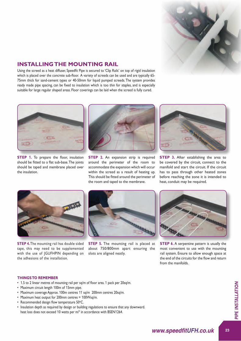
STEP 1. To prepare the floor, insulation should be fitted to a flat sub-base. The joints should be taped and membrane placed over the insulation.
STEP 4. The mounting rail has double sided tape, this may need to be supplemented with the use of JGUFHPIN depending on the adhesions of the installation.
STEP 3. After establishing the area to be covered by the circuit, connect to the manifold and start the circuit. If the circuit has to pass through other heated zones before reaching the zone it is intended to heat, conduit may be required.
STEP 6. A serpentine pattern is usually the most convenient to use with the mounting rail system. Ensure to allow enough space at the end of the circuits for the flow and return from the manifolds.
STEP 2. An expansion strip is required around the perimeter of the room to accommodate the expansion which will occur within the screed as a result of heating up. This should be fitted around the perimeter of the room and taped to the membrane.
STEP 5. The mounting rail is placed at about 750/800mm apart ensuring the slots are aligned neatly.
Using the screed as a heat diffuser, Speedfit Pipe is secured to ‘Clip Rails’ on top of rigid insulation which is placed over the concrete sub-floor. A variety of screeds can be used and are typically 65-75mm thick for sand-cement types or 40-50mm for liquid pumped screeds. The system provides ready made pipe spacing, can be fixed to insulation which is too thin for staples, and is especially suitable for large regular shaped areas. Floor coverings can be laid when the screed is fully cured.
INSTALLING THE MOUNTING RAIL
23www.speedfitUFH.co.uk
PIPE
INST
ALLA
TIO
N
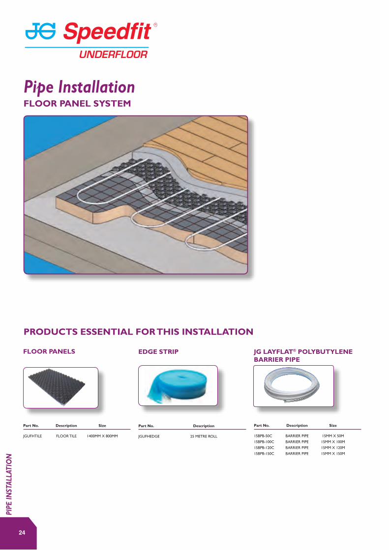
FLOOR PANEL SYSTEM
Pipe Installation
24
PIPE
INST
ALLA
TIO
N
Part No. Description Size
JGUFHTILE FLOOR TILE 1400MM X 800MM
FLOOR PANELS
Part No. Description
JGUFHEDGE 25 METRE ROLL
EDGE STRIP
PRODUCTS ESSENTIAL FOR THIS INSTALLATION
Part No. Description Size
15BPB-50C BARRIER PIPE 15MM X 50M
15BPB-100C BARRIER PIPE 15MM X 100M
15BPB-120C BARRIER PIPE 15MM X 120M
15BPB-150C BARRIER PIPE 15MM X 150M
JG LAYFLAT® POLYBUTYLENE BARRIER PIPE
THINGS TO REMEMBER • BS EN 1264-4 recommends that an expansion joint is constructed in stone and ceramic finished screeds for every 40m2 of floor area at a maximum length of 8m and an aspect ration of 2:1. An expansion joint is also required in long narrow areas such corridors etc.
• Insulation depth as required by design or building regulations and to ensure that any downward heat loss does not exceed 10 watts per m/2 in accordance with BSEN1264.
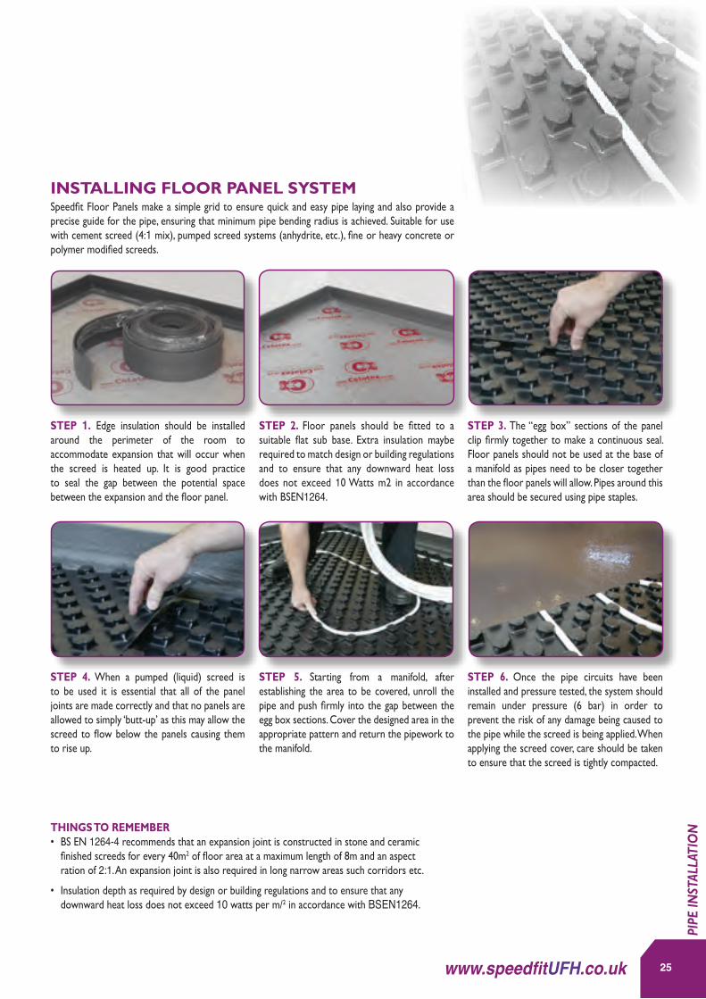
STEP 1. Edge insulation should be installed around the perimeter of the room to accommodate expansion that will occur when the screed is heated up. It is good practice to seal the gap between the potential space between the expansion and the floor panel.
Speedfit Floor Panels make a simple grid to ensure quick and easy pipe laying and also provide a precise guide for the pipe, ensuring that minimum pipe bending radius is achieved. Suitable for use with cement screed (4:1 mix), pumped screed systems (anhydrite, etc.), fine or heavy concrete or polymer modified screeds.
STEP 4. When a pumped (liquid) screed is to be used it is essential that all of the panel joints are made correctly and that no panels are allowed to simply ‘butt-up’ as this may allow the screed to flow below the panels causing them to rise up.
STEP 3. The “egg box” sections of the panel clip firmly together to make a continuous seal. Floor panels should not be used at the base of a manifold as pipes need to be closer together than the floor panels will allow. Pipes around this area should be secured using pipe staples.
STEP 6. Once the pipe circuits have been installed and pressure tested, the system should remain under pressure (6 bar) in order to prevent the risk of any damage being caused to the pipe while the screed is being applied. When applying the screed cover, care should be taken to ensure that the screed is tightly compacted.
STEP 2. Floor panels should be fitted to a suitable flat sub base. Extra insulation maybe required to match design or building regulations and to ensure that any downward heat loss does not exceed 10 Watts m2 in accordance with BSEN1264.
STEP 5. Starting from a manifold, after establishing the area to be covered, unroll the pipe and push firmly into the gap between the egg box sections. Cover the designed area in the appropriate pattern and return the pipework to the manifold.
INSTALLING FLOOR PANEL SYSTEM
25www.speedfitUFH.co.uk
PIPE
INST
ALLA
TIO
N

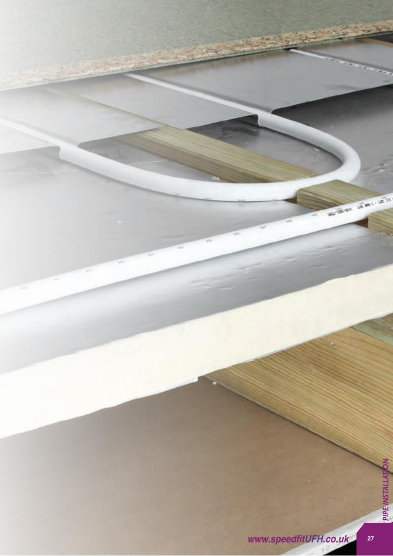
Timber and floating floors generally use heat spreader plates to transfer the heat from the pipes. There are many variations of these floor types and particular requirements should be discussed with our Technical Support Team.
Speedfit Pipe is installed into grooved aluminum plates which are first fixed from above in the case of traditional joists or from below when engineered I-Beam Joist systems are used. If the floor can be raised, floors can also be counter-battened to make installation even easier. Insulation is installed below the plates and it is important that the floor decking is in contact with the plate to maximise output.
SPREADER PLATES
UNDERFIT
SUSPENDED TIMBER FLOORS
26
Pipe Installation
PIPE
INST
ALLA
TIO
N
27www.speedfitUFH.co.uk
PIPE
INST
ALLA
TIO
N
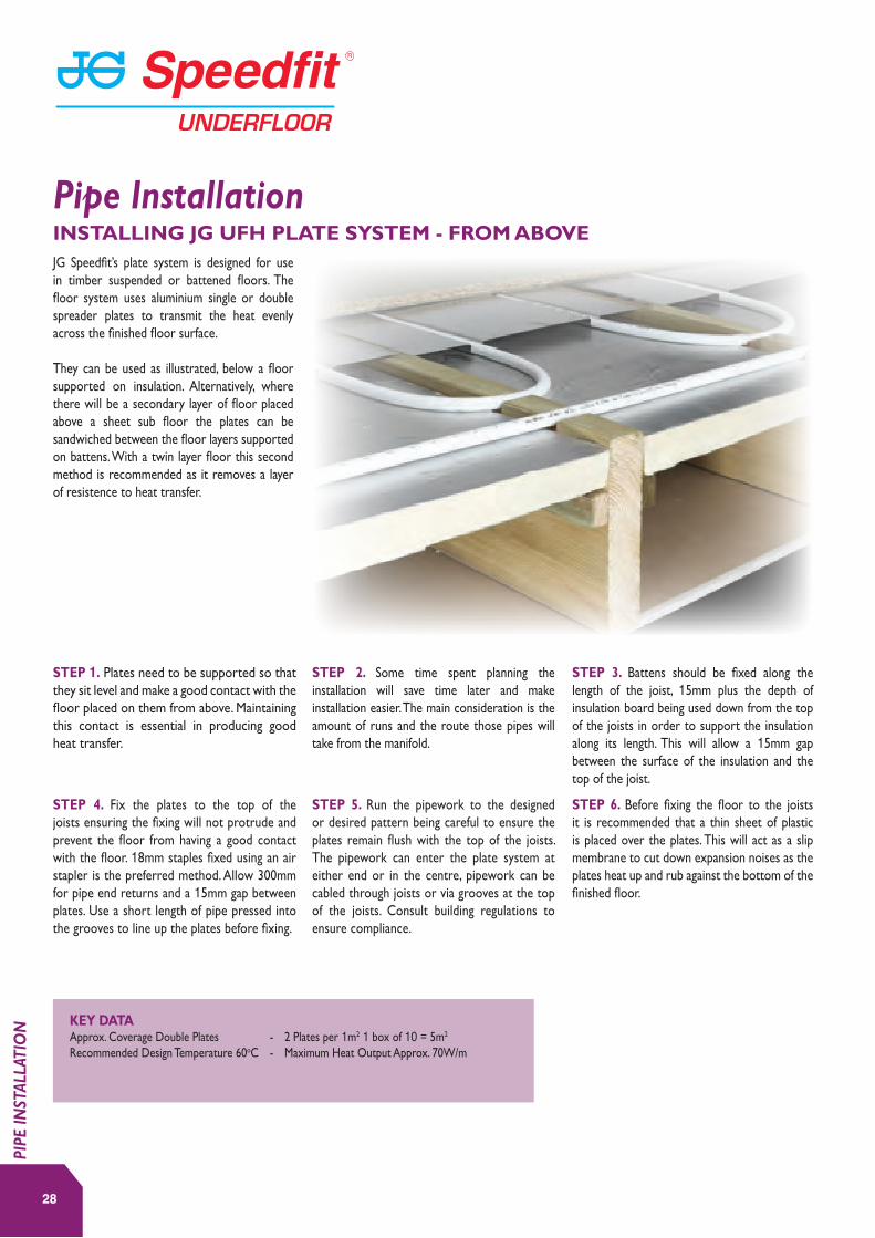
STEP 1. Plates need to be supported so that they sit level and make a good contact with the floor placed on them from above. Maintaining this contact is essential in producing good heat transfer.
STEP 4. Fix the plates to the top of the joists ensuring the fixing will not protrude and prevent the floor from having a good contact with the floor. 18mm staples fixed using an air stapler is the preferred method. Allow 300mm for pipe end returns and a 15mm gap between plates. Use a short length of pipe pressed into the grooves to line up the plates before fixing.
STEP 3. Battens should be fixed along the length of the joist, 15mm plus the depth of insulation board being used down from the top of the joists in order to support the insulation along its length. This will allow a 15mm gap between the surface of the insulation and the top of the joist.
STEP 6. Before fixing the floor to the joists it is recommended that a thin sheet of plastic is placed over the plates. This will act as a slip membrane to cut down expansion noises as the plates heat up and rub against the bottom of the finished floor.
STEP 2. Some time spent planning the installation will save time later and make installation easier. The main consideration is the amount of runs and the route those pipes will take from the manifold.
STEP 5. Run the pipework to the designed or desired pattern being careful to ensure the plates remain flush with the top of the joists. The pipework can enter the plate system at either end or in the centre, pipework can be cabled through joists or via grooves at the top of the joists. Consult building regulations to ensure compliance.
KEY DATA Approx. Coverage Double Plates - 2 Plates per 1m2 1 box of 10 = 5m2
Recommended Design Temperature 60oC - Maximum Heat Output Approx. 70W/m
JG Speedfit’s plate system is designed for use in timber suspended or battened floors. The floor system uses aluminium single or double spreader plates to transmit the heat evenly across the finished floor surface.
They can be used as illustrated, below a floor supported on insulation. Alternatively, where there will be a secondary layer of floor placed above a sheet sub floor the plates can be sandwiched between the floor layers supported on battens. With a twin layer floor this second method is recommended as it removes a layer of resistence to heat transfer.
28
INSTALLING JG UFH PLATE SYSTEM - FROM ABOVE
PIPE
INST
ALLA
TIO
N
Pipe Installation
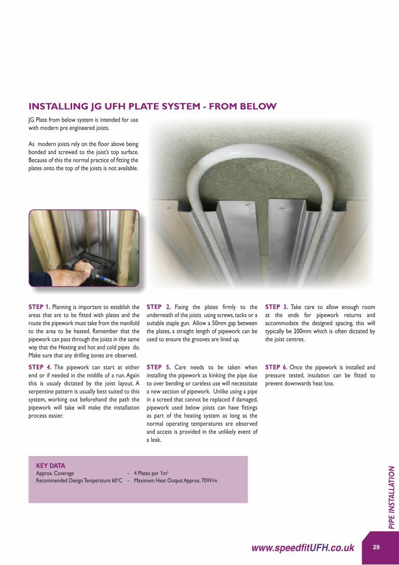
STEP 1. Planning is important to establish the areas that are to be fitted with plates and the route the pipework must take from the manifold to the area to be heated. Remember that the pipework can pass through the joists in the same way that the Heating and hot and cold pipes do. Make sure that any drilling zones are observed.
STEP 4. The pipework can start at either end or if needed in the middle of a run. Again this is usualy dictated by the joist layout. A serpentine pattern is usually best suited to this system, working out beforehand the path the pipework will take will make the installation process easier.
STEP 3. Take care to allow enough room at the ends for pipework returns and accommodate the designed spacing, this will typically be 200mm which is often dictated by the joist centres.
STEP 6. Once the pipework is installed and pressure tested, insulation can be fitted to prevent downwards heat loss.
STEP 2. Fixing the plates firmly to the underneath of the joists using screws, tacks or a suitable staple gun. Allow a 50mm gap between the plates, a straight length of pipework can be used to ensure the grooves are lined up.
STEP 5. Care needs to be taken when installing the pipework as kinking the pipe due to over bending or careless use will necessitate a new section of pipework. Unlike using a pipe in a screed that cannot be replaced if damaged, pipework used below joists can have fittings as part of the heating system as long as the normal operating temperatures are observed and access is provided in the unlikely event of a leak.
KEY DATA Approx. Coverage - 4 Plates per 1m2 Recommended Design Temperature 60oC - Maximum Heat Output Approx. 70W/m
JG Plate from below system is intended for use with modern pre engineered joists.
As modern joists rely on the floor above being bonded and screwed to the joist’s top surface. Because of this the normal practice of fitting the plates onto the top of the joists is not available.
29www.speedfitUFH.co.uk
INSTALLING JG UFH PLATE SYSTEM - FROM BELOW
PIPE
INST
ALLA
TIO
N
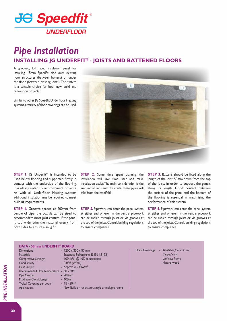
STEP 1. JG ‘Underfit®’ is intended to be used below flooring and supported firmly in contact with the underside of the flooring. It is ideally suited to refurbishment projects. As with all Underfloor Heating systems additional insulation may be required to meet building requirements.
STEP 4. Grooves spaced at 200mm from centre of pipe, the boards can be sized to accommodate most joist centres. If the panel is too wide, trim the material evenly from both sides to ensure a snug fit.
STEP 3. Battens should be fixed along the length of the joist, 50mm down from the top of the joists in order to support the panels along its length. Good contact between the surface of the panel and the bottom of the flooring is essential in maximising the performance of this system.
STEP 2. Some time spent planning the installation will save time later and make installation easier. The main consideration is the amount of runs and the route these pipes will take from the manifold.
STEP 5. Pipework can enter the panel system at either end or even in the centre, pipework can be cabled through joists or via grooves at the top of the joists. Consult building regulations to ensure compliance.
STEP 6. Pipework can enter the panel system at either end or even in the centre, pipework can be cabled through joists or via grooves at the top of the joists. Consult building regulations to ensure compliance.
DATA - 50mm UNDERFIT® BOARDDimensions - 1200 x 350 x 50 mmMaterials - Expanded Polystyrene BS EN 13163Compressive Strength - 100 (kPa) @ 10% compressionConductivity - 0.036 (W/mk)Heat Output - Approx 50 - 60w/m2
Recommended Flow Temperature - 50 - 60oCPipe Centres - 200mmMaximum Circuit Length - 100mTypical Coverage per Loop - 15 - 20m2
Applications - New Build or renovation, single or multiple rooms
Floor Coverings - Tiles/slate,/ceramic etc. Carpet/Vinyl Laminate floors Natural wood
A grooved, foil faced insulation panel for installing 15mm Speedfit pipe over existing floor structures (between battens) or under the floor (between existing joists). The system is a suitable choice for both new build and renovation projects.
Similar to other JG Speedfit Underfloor Heating systems, a variety of floor coverings can be used.
INSTALLING JG UNDERFIT® - JOISTS AND BATTENED FLOORS
Pipe Installation
30
PIPE
INST
ALLA
TIO
N
31www.speedfitUFH.co.uk
PIPE
INST
ALLA
TIO
N

NOTE: In order to prevent movement and subsequent cracking, when planning to lay a tiled floor the following recommendations should be followed. A heavy lapped backer board should be used.
The Overfit should be fitted to a flat surface giving sufficient support for the boards and intended use. Good building practice should be observed and the tile & backer board manufacturers recommendations should be followed.
32
RETROFIT (OVERFIT)
Pipe Installation
PIPE
INST
ALLA
TIO
N
THINGS TO REMEMBER Dimensions – 1250 x 600 x 25mm BoardHeat Output – Approx 50-60 w/m2
Pipe Centres – 150mmMaximum Circuit length – 100m
Part No. Description Size
JGUFHBOARD1 OVERFIT BOARD 1250MM X 600MM
OVERFIT® BOARD
Part No. Description
JGUFHEDGE 25 METRE ROLL
EDGE STRIP
PRODUCTS ESSENTIAL FOR THIS INSTALLATION
Part No. Description Size
15BPB-50C BARRIER PIPE 15MM X 50M
15BPB-100C BARRIER PIPE 15MM X 100M
15BPB-120C BARRIER PIPE 15MM X 120M
15BPB-150C BARRIER PIPE 15MM X 150M
JG LAYFLAT® POLYBUTYLENE BARRIER PIPE

DATA - 25mm OVERFIT® BOARDDimensions - 1250 x 600 x 25mmMaterials - Extruded Polystyrene-XPS2 (BS EN 13164)Compressive Strength - 250 (kPa) @ 10% compressionConductivity - 0.029 (W/mk)Heat Output - Approx 50 - 60w/m2
Recommended Flow Temperature - 50 - 60oCPipe Centres - 150mmMaximum Circuit Length - 100mTypical Coverage per Loop - 13 - 15m2
Applications - New Build or renovation, single or multiple rooms
Floor Coverings Tiles/slate/ceramic etc. - use with Knauff Brio Board or eqivalent.
Carpet/vinyl - use with suitable plywood covering.
Laminate floors - use directly over insulation as floating floor.
Natural wood - fix to battens between panels.
STEP 4. Start laying the pipework by pressing it firmly into the grooves. Where the pipework is connected to the manifold there will be a need to use plain insulation and pipe staples to accommodate the closer pipe centres.
STEP 3. After placing the boards and ensuring they are flat and level and the joints are butted up firmly. Tape the joints using JGTAPE.
STEP 6. After installing the pipework JGTAPE can be placed over the end loops to prevent the pipework from becoming dislodged during the installation of the finished floor.
STEP 2. Plates need to be supported so that they sit level and make a good contact with the floor placed on them from above. Maintaining this contact is essential in producing good heat transfer.
STEP 5. Where the pipe changes direction cut the foil in the return loops using a craft knife to prevent damage to the board. This will ensure a tight fit for the pipework.
STEP 1. The main consideration is the amount of runs and the route those pipes will take from the manifold. If more transit grooves are needed then the grooves at the opposite ends can be cut off and used. Where possible route pipes through rather than around walls and doorways to cut down on pipework congestion. When lining up panels use a short length of pipe placed in the grooves to align them together.
JG UFH Overfit® is a low profile System for new build or renovation projects.
JG Overfit® is a lightweight insulated panel with high compressive strength intended for use with lightweight floor coverings, e.g. laminate, engineered wood and carpet. Due to its ease of handling and cutting it is also suitable for larger areas and multiple room installations.
The installation uses 15mm pipe and 150mm centres for a highly responsive system.
33www.speedfitUFH.co.uk
INSTALLING THE JG OVERFIT® SYSTEM
PIPE
INST
ALLA
TIO
N
34
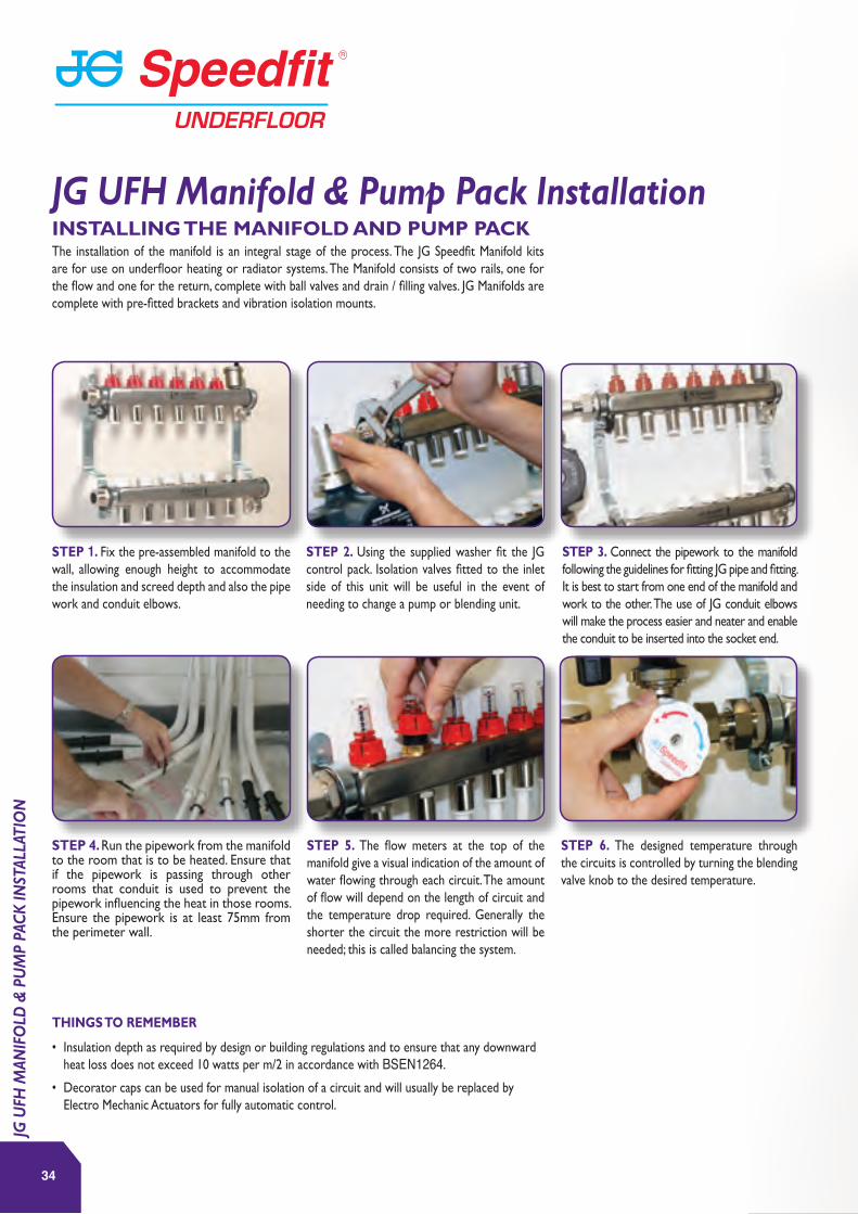
The installation of the manifold is an integral stage of the process. The JG Speedfit Manifold kits are for use on underfloor heating or radiator systems. The Manifold consists of two rails, one for the flow and one for the return, complete with ball valves and drain / filling valves. JG Manifolds are complete with pre-fitted brackets and vibration isolation mounts.
THINGS TO REMEMBER
• Insulation depth as required by design or building regulations and to ensure that any downward heat loss does not exceed 10 watts per m/2 in accordance with BSEN1264.
• Decorator caps can be used for manual isolation of a circuit and will usually be replaced by Electro Mechanic Actuators for fully automatic control.
STEP 1. Fix the pre-assembled manifold to the wall, allowing enough height to accommodate the insulation and screed depth and also the pipe work and conduit elbows.
STEP 4. Run the pipework from the manifold to the room that is to be heated. Ensure that if the pipework is passing through other rooms that conduit is used to prevent the pipework influencing the heat in those rooms. Ensure the pipework is at least 75mm from the perimeter wall.
STEP 3. Connect the pipework to the manifold following the guidelines for fitting JG pipe and fitting. It is best to start from one end of the manifold and work to the other. The use of JG conduit elbows will make the process easier and neater and enable the conduit to be inserted into the socket end.
STEP 6. The designed temperature through the circuits is controlled by turning the blending valve knob to the desired temperature.
STEP 2. Using the supplied washer fit the JG control pack. Isolation valves fitted to the inlet side of this unit will be useful in the event of needing to change a pump or blending unit.
STEP 5. The flow meters at the top of the manifold give a visual indication of the amount of water flowing through each circuit. The amount of flow will depend on the length of circuit and the temperature drop required. Generally the shorter the circuit the more restriction will be needed; this is called balancing the system.
INSTALLING THE MANIFOLD AND PUMP PACK
JG UFH Manifold & Pump Pack Installation
JG U
FH M
ANIF
OLD
& P
UM
P PA
CK
INST
ALLA
TIO
N

35www.speedfitUFH.co.uk
JG U
FH M
ANIF
OLD
& P
UM
P PA
CK
INST
ALLA
TIO
N

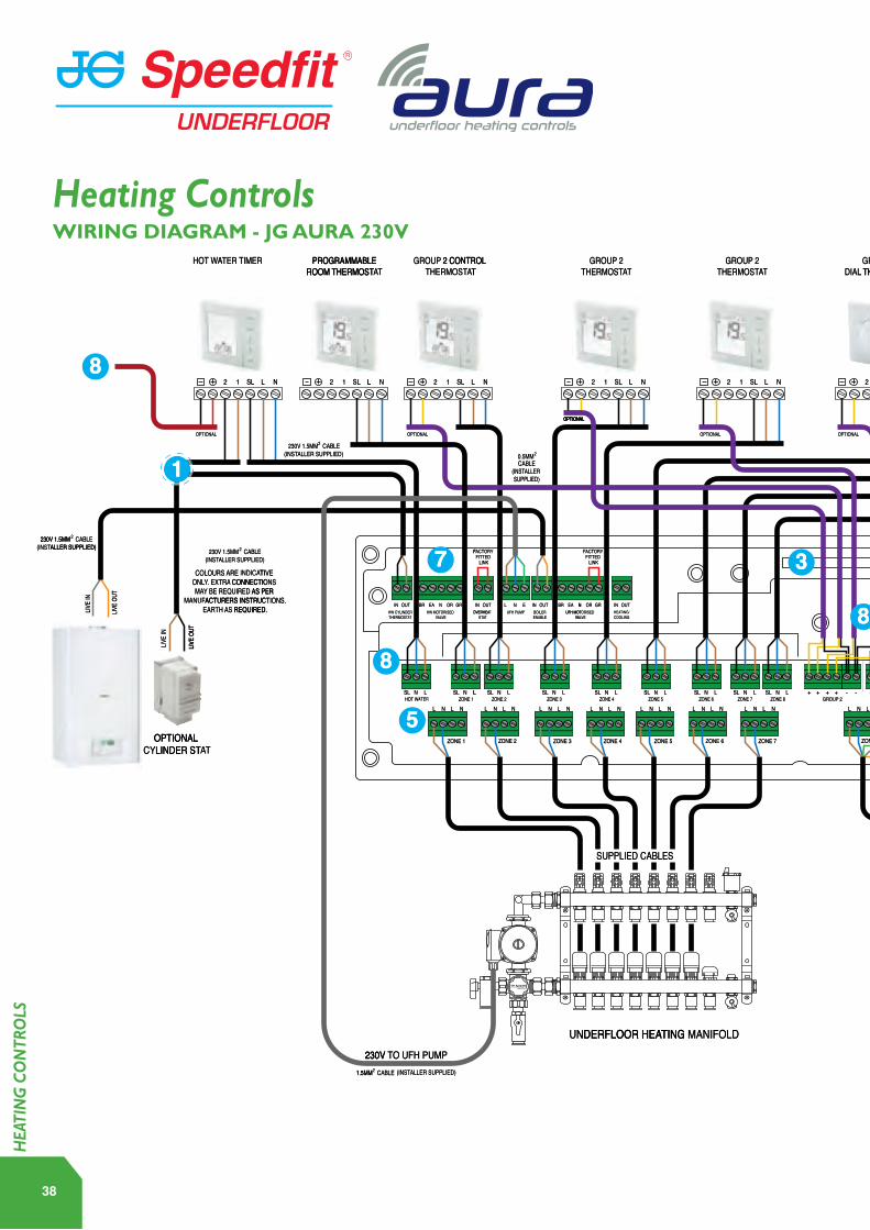
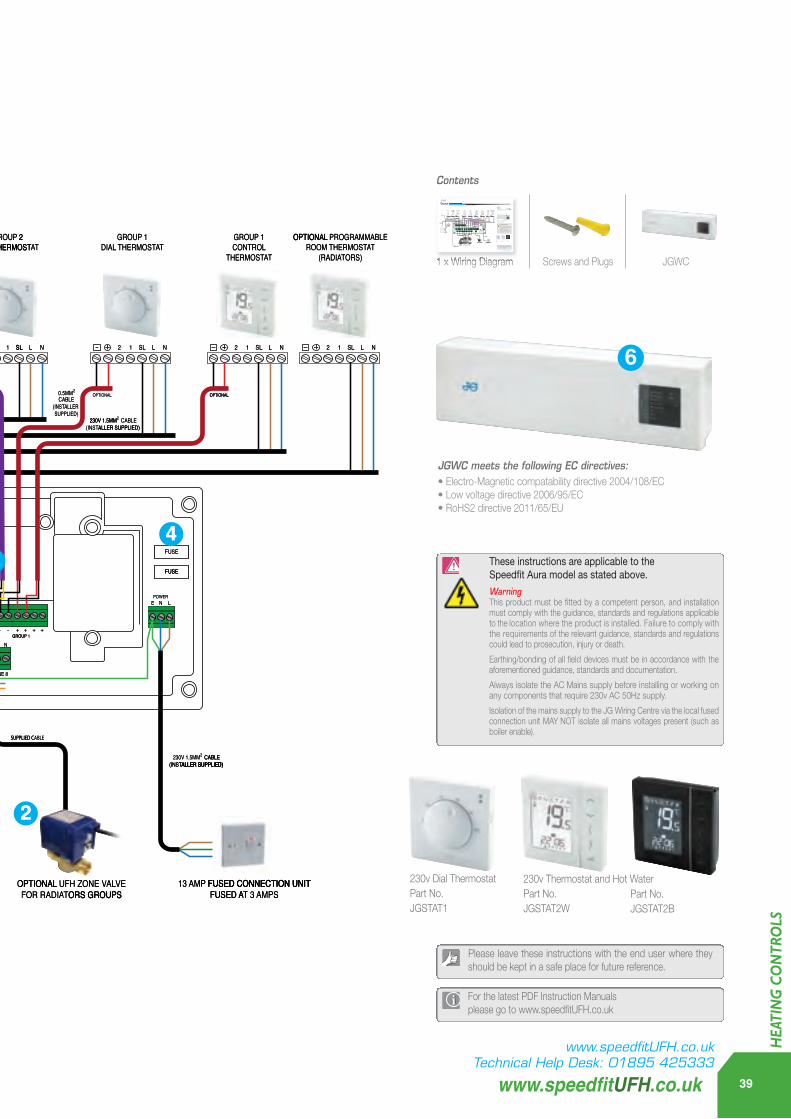
At the heart of the JG Aura 230v range is once again our unique 4 in 1 JG Aura thermostat, providing combined control of UFH and radiators allowing simple installation of multi zone energy saving systems in new or retrofit projects. The thermostat can operate as a Programmable Room Thermostat, Group Control Thermostat, Group Thermostat and a Hot Water Timer.
To enable the Group Control functionality it is essential that a 0.5mm 2 core data cable is utilised within the wiring process. The Group Control Thermostat can control a variation of both digital thermostats and dial thermostats from one central location. The optional data cable will not be required if the thermostats are to be used as individual Programmable Room Thermostats.
The Group Control Thermostat can control up to eight thermostats plus a Hot Water Timer.
The unique JG Aura 4 in 1 wireless thermostat is designed to present wireless control of your underfloor heating system including unique wireless boiler communication when installing the JG Aura Boiler Receiver. The JG Aura wireless thermostat is designed to work with the JG Aura app when incorporating the internet hub, presenting you ultimate control of time and temperature for your underfloor heating and hot water wherever you are in the world. The stylish slim line thermostats offer touch sensitive control at your fingertips. Uniquely, the installer is presented with two options of powering the thermostat, using either batteries or simply mains powered.
At the heart of the range is the unique JG Aura thermostat that can operate in 4 easily configured modes, Programmable Room Thermostat, Group Control Thermostat, Group Thermostat or Hot Water Timer and can be used as Programmable Room Thermostat or combined into groups allowing convenient group control of many functions from one central place.
For use with the JG Aura Wireless Range. The JG Aura App gives you the freedom to control your underfloor heating and hot water no matter where you are via smart phone, tablet or desktop computer. The easy to use interface and intuitive nature of the JG Aura app, makes control of your heating system completely accessible from anywhere and at any time that suits you.
For more information please visit www.speedfitUFH.co.uk
36
JG AURA 230V CONTROLS
JG AURA WIRELESS CONTROLS
JG APP CONTROL
Heating Controls - 3 Options
HEA
TIN
G C
ON
TRO
LS DISCLAIMERCustomers that choose to operate their heating remotely using JG Aura Range technology via their personal computer, tablet or smart phone device(s) will be entering into a contract with Salus Controls plc (“Salus”), which is a third party supplier of the software. John Guest Ltd and affiliates within the John Guest group of companies from time to time (the “John Guest Group”) make no representations or warranties of any kind about the reliability or suitability of the software or applications provided by Salus. The John Guest Group disclaims liability (excluding liability for death and personal injury resulting from negligence) for any loss or damage caused by the software provided to customers by Salus. Any agreement entered into with Salus is therefore strictly at your own risk.

37www.speedfitUFH.co.uk
HEA
TIN
G C
ON
TRO
LS
SL L N12+
LIVE I
N
LIVE O
UT
FUSE
FUSE
SUPPLIED CABLES
230V TO UFH PUMP
UNDERFLOOR HEATING MANIFOLD
1.5MM2 CABLE (INSTALLER SUPPLIED)
230V 1.5MM2 CABLE(INSTALLER SUPPLIED) 230V 1.5MM2 CABLE
(INSTALLER SUPPLIED)
230V 1.5MM2 CABLE(INSTALLER SUPPLIED)
230V 1.5MM2 CABLE(INSTALLER SUPPLIED)
230V 1.5MM2 CABLE(INSTALLER SUPPLIED)
OPTIONAL CYLINDER STAT
LIVE I
N
LIVE O
UT
COLOURS ARE INDICATIVE ONLY. EXTRA CONNECTIONS MAY BE REQUIRED AS PER
MANUFACTURERS INSTRUCTIONS.EARTH AS REQUIRED.
ZONE 1
SL N L SL N L SL N L SL N L SL N L SL N L SL N LGROUP 2 GROUP 1
POWER
N L + + + + + + + +- - - -SL SLN L
ZONE 2
FACTORY FITTED
LINK
ZONE 3 ZONE 4 ZONE 5 ZONE 6 ZONE 7 ZONE 8
SL L N12 SL L N12++ SL L N12+ SL L N12+ SL L N12+ SL L N12+ SL L N12+ SL L N12+
0.5MM2
CABLE(INSTALLER SUPPLIED)0.5MM2
CABLE(INSTALLER SUPPLIED)
L N L N L N L N L N L N L N L N L N L N L N L N L N L N L N L N
E N L
1
FACTORY FITTED
LINK
HW CYLINDERTHERMOSTAT
HW MOTORISED VALVE
HOT WATER
OPTIONAL OPTIONAL OPTIONAL OPTIONAL OPTIONAL OPTIONAL
OPTIONAL
ZONE 1 ZONE 2 ZONE 3 ZONE 4 ZONE 5 ZONE 6 ZONE 7 ZONE 8
UFH MOTORISED VALVE
OVERHEAT STAT
IN OUT IN OUT IN OUTBR EA N NL EOR GR BR EA N OR GRUFH PUMP BOILER
ENABLE
IN OUTHEATING/COOLING
8
7
8
5
84
3
SUPPLIED CABLE
2
13 AMP FUSED CONNECTION UNITFUSED AT 3 AMPS
HOT WATER TIMER PROGRAMMABLEROOM THERMOSTAT
GROUP 2 CONTROL THERMOSTAT
GROUP 2THERMOSTAT
GROUP 2THERMOSTAT
GROUP 2DIAL THERMOSTAT
GROUP 1DIAL THERMOSTAT
GROUP 1CONTROL
THERMOSTAT
OPTIONAL PROGRAMMABLEROOM THERMOSTAT
(RADIATORS)
OPTIONAL UFH ZONE VALVEFOR RADIATORS GROUPS
TIMERTER AATER WHOT
ROOM THERMOST
PROGRAMMABLE
TAATTHERMOSTTA
2 CONTROLGROUPTAATROOM THERMOST
PROGRAMMABLE
T
2 CONTROL
TAATTHERMOST
2GROUP
TAATTHERMOST
2GROUP
THERMOSTDIAL
2GROUP
DIALTAAT THERMOST
2
TAAT THERMOST
1GROUP
OPTIONAL
TAATTHERMOSTCONTROL
1GROUP
ORS)T(RADIAATTAATROOM THERMOST T
PROGRAMMABLEOPTIONAL
8
2 1 LSL+
N 2 1 LSL+
NL 2 1 LSL+
+N
OPTIONAL
2 1 NLSL+
OPTIONAL
2 1 NLSL+
2 1 SL+
NLSL +
2 1 NLSL
2 1 NLSL+
2 1 NLSL+
1OPTIONAL
ALLER SUPPLIED)(INSTCABLE2230V 1.5MM
OPTIONAL
SUPPLIED)ALLER (INSTA
CABLE20.5MM
OPTIONAL
OPTIONAL
OPTIONAL
OPTIONAL
ALLER SUPPLIED)(INST230V 1.5MM
SUPPLIED)ALLER (INST
CABLE20.5MM OPTIONAL
ALLER SUPPLIED)CABLE2230V 1.5MM
OPTIONAL
OPTIONAL
ALLER SUPPLIED)(INST230V 1.5MM
LIVE O
UT
LIVE I
N
ALLER SUPPLIED)CABLE2230V 1.5MM
ALLER SUPPLIED)(INSTCABLE2230V 1.5MM
REQUIRED.TH AS EARACTURERS INSTRUCMANUFF
AS PER BE REQUIRED YMA CONNECTIO . EXTRA A CONNECTIONS YY. EXTRAONL
TI INDICAATIVE COLOURS ARE
LIVE O
UT
REQUIRED.ACTURERS INSTRUCTIONS.
AS PER CONNECTIONS
TIVE
F
GRORNEABROUTINOVERHEA
ELVVAORISED HW MOT
TAATTHERMOSTHW CYLINDER
7
LINKFITTED
Y RTOCAF
ENABLEBOILERUFH PUMP
NEABREL N OUTINOUTIN
TATSTOVERHEAAT
VAUFH MOT
LINKFITTED
Y RTOCAF
COOLINGTING/HEAATING/OUTINGRORN
ELVVAORISED UFH MOT
8
3
FUSE
FUSE
4
LIVE O
UT
LIVE I
N
LNSLLNSL
NLNLZONE 1TERAT WHOT
8
5
LNSLLNSLL
NLNLNLNLZONE 3ZONE 2
LNSLLNSL
NLNLNLNLZONE 5ZONE 4
LN SLSL LNLNSL
NLNLNLNLZONE 8ZONE 7ZONE 6
---- +++++GROUP 2GROUP
NLNL
+++ 1GROUP
FUSE
POWERLNE
CYLINDER STOPTIONAL
TAATINDER ST TAOPTIONAL
ZONE 1
ZONE 3ZONE 2
ZONE 5ZONE 4
ZONE 7ZONE 6
ZONE 8
SUPPLIED C
ABLESUPPLIED C
ALLER SUPPLIED)(INSTCABLE2230V 1.5MM
ALLER SUPPLIED)CABLE
SUPPLIED CABLES
2
ALLER SUPPLIED)(INST
ALLER SUPPLIED)
UNDERFLOOR HEA
TING MANIFOLDNDERFLOOR HEA A
TING MANIFOLD
OPTIONAL
ORS GROUPSTFOR RADIA AALL UFH ZONE V VALOPTIONAL
FUSED A FUSED CONNECTION UNITAMP13
ORS GROUPSVE
3 AMPSTFUSED A AT FUSED CONNECTION UNIT
FUSED CONNECTION UNIT
1.5MM
230V
ALLER SUPPLIED)(INSTCABLE21.5MM
O UFH PUMPT230V
Wiring Diagram and Instruction Manual
JGWC - 230v 8 Zone Wiring CentreZ2105/414/1114
JGWC meets the following EC directives:• Electro-Magnetic compatability directive 2004/108/EC• Low voltage directive 2006/95/EC• RoHS2 directive 2011/65/EU
Please note: The information below displays a typical installation for illustration purposes only.
www.speedfitUFH.co.ukTechnical Help Desk: 01895 425333
Please leave these instructions with the end user where theyshould be kept in a safe place for future reference.
For the latest PDF Instruction Manuals please go to www.speedfitUFH.co.uk
230v Dial ThermostatPart No. JGSTAT1
230v Thermostat and Hot WaterPart No. JGSTAT2W
Part No. JGSTAT2B
1 x Wiring Diagram Screws and Plugs JGWC
Contents
SL L N12+
LIVE I
N
LIVE O
UT
FUSE
FUSE
SUPPLIED CABLES
230V TO UFH PUMP
UNDERFLOOR HEATING MANIFOLD
1.5MM2 CABLE (INSTALLER SUPPLIED)
230V 1.5MM2 CABLE(INSTALLER SUPPLIED) 230V 1.5MM2 CABLE
(INSTALLER SUPPLIED)
230V 1.5MM2 CABLE(INSTALLER SUPPLIED)
230V 1.5MM2 CABLE(INSTALLER SUPPLIED)
230V 1.5MM2 CABLE(INSTALLER SUPPLIED)
OPTIONAL CYLINDER STAT
LIVE I
N
LIVE O
UT
COLOURS ARE INDICATIVE ONLY. EXTRA CONNECTIONS MAY BE REQUIRED AS PER
MANUFACTURERS INSTRUCTIONS.EARTH AS REQUIRED.
ZONE 1
SL N L SL N L SL N L SL N L SL N L SL N L SL N LGROUP 2 GROUP 1
POWER
N L + + + + + + + +- - - -SL SLN L
ZONE 2
FACTORY FITTED
LINK
ZONE 3 ZONE 4 ZONE 5 ZONE 6 ZONE 7 ZONE 8
SL L N12 SL L N12++ SL L N12+ SL L N12+ SL L N12+ SL L N12+ SL L N12+ SL L N12+
0.5MM2
CABLE(INSTALLER SUPPLIED)0.5MM2
CABLE(INSTALLER SUPPLIED)
L N L N L N L N L N L N L N L N L N L N L N L N L N L N L N L N
E N L
1
FACTORY FITTED
LINK
HW CYLINDERTHERMOSTAT
HW MOTORISED VALVE
HOT WATER
OPTIONAL OPTIONAL OPTIONAL OPTIONAL OPTIONAL OPTIONAL
OPTIONAL
ZONE 1 ZONE 2 ZONE 3 ZONE 4 ZONE 5 ZONE 6 ZONE 7 ZONE 8
UFH MOTORISED VALVE
OVERHEAT STAT
IN OUT IN OUT IN OUTBR EA N NL EOR GR BR EA N OR GRUFH PUMP BOILER
ENABLE
IN OUTHEATING/COOLING
8
7
8
5
84
3
SUPPLIED CABLE
2
13 AMP FUSED CONNECTION UNITFUSED AT 3 AMPS
HOT WATER TIMER PROGRAMMABLEROOM THERMOSTAT
GROUP 2 CONTROL THERMOSTAT
GROUP 2THERMOSTAT
GROUP 2THERMOSTAT
GROUP 2DIAL THERMOSTAT
GROUP 1DIAL THERMOSTAT
GROUP 1CONTROL
THERMOSTAT
OPTIONAL PROGRAMMABLEROOM THERMOSTAT
(RADIATORS)
OPTIONAL UFH ZONE VALVEFOR RADIATORS GROUPS
TIMERTER AA WHOT
ROOM THERMOST
PROGRAMMABLE
TATHERMOST
2 CONTROLGROUPTAATROOM THERMOST
PROGRAMMABLE
T
2 CONTROL
TAATHERMOST
2GROUP
TAATHERMOST
2GROUP
THERMOSTDIAL
2GROUP
DIALTAAT THERMOST
2
TAAT THERMOST
1GROUP
OPTIONAL
TATTHERMOSTCONTROL
1GROUP
ORS)T(RADIAATATROOM THERMOSTA
PROGRAMMABLEOPTIONAL
8
2 1 LSL+
N 2 1 LSL+
NL 2 1 LSL+
+N
OPTIONAL
2 1 NLSL+
OPTIONAL
2 1 NLSL+
2 1 SL+
NLSL +
2 1 NLSL
2 1 NLSL+
2 1 NLSL+
1OPTIONAL
ALLER SUPPLIED)(INSTCABLE2230V 1.5MM
OPTIONAL
SUPPLIED)ALLER (INST
CABLE20.5MM
OPTIONAL
OPTIONAL
OPTIONAL
OPTIONAL
ALLER SUPPLIED)(INST230V 1.5MM
SUPPLIED)ALLER (INST
CABLE20.5MM OPTIONAL
ALLER SUPPLIED)CABLE2230V 1.5MM
OPTIONAL
OPTIONAL
ALLER SUPPLIED)(INST230V 1.5MM
LIVE O
UT
LIVE I
N
ALLER SUPPLIED)CABLE2230V 1.5MM
ALLER SUPPLIED)(INSTCABLE2230V 1.5MM
REQUIRED.TH AS EARACTURERS INSTRUCMANUF
AS PER BE REQUIRED YMA CONNECTIO . EXTRA YY. EXTRAONL
TI INDICAA COLOURS ARE
LIVE O
UT
REQUIRED.ACTURERS INSTRUCTIONS.
AS PER CONNECTIONS
TIVE
F
GRORNEABROUTINOVERHEA
ELVVAORISED HW MOT
TAATTHERMOSTHW CYLINDER
7
LINKFITTED
Y RTOCAF
ENABLEBOILERUFH PUMP
NEABREL N OUTINOUTIN
TATSTOVERHEAA
VAUFH MOT
LINKFITTED
Y RTOCAF
COOLINGTING/HEAATOUTINGRORN
ELVVAORISED UFH MOT
8
3
FUSE
FUSE
4
LIVE O
UT
LIVE I
N
LNSLLNSL
NLNLZONE 1TERAAT WHOT
8
5
LNSLLNSLL
NLNLNLNLZONE 3ZONE 2
LNSLLNSL
NLNLNLNLZONE 5ZONE 4
LN SLSL LNLNSL
NLNLNLNLZONE 8ZONE 7ZONE 6
---- +++++GROUP 2GROUP
NLNL
+++ 1GROUP
FUSE
POWERLNE
CYLINDER STOPTIONAL
TAAINDER ST AOPTIONAL
ZONE 1
ZONE 3ZONE 2
ZONE 5ZONE 4
ZONE 7ZONE 6
ZONE 8
SUPPLIED C
ABLESUPPLIED C
ALLER SUPPLIED)(INSTCABLE2230V 1.5MM
ALLER SUPPLIED)CABLE
SUPPLIED CABLES
2
ALLER SUPPLIED)(INST
ALLER SUPPLIED)
UNDERFLOOR HEA
TING NDERFLOOR HEA
TING MANIFOLD
OPTIONAL
ORS GROUPSTFOR RADIA ATAL UFH ZONE V VAPTIONAL
FUSED A FUSED CONNECTION UNITAMP13
ORS GROUPSVE
3 AMPSTFUSED A A FUSED CONNECTION UNIT
FUSED CONNECTION UNIT
1.5MM
230V
ALLER SUPPLIED)(INSTCABLE21.5MM
O UFH PUMPT230V
Wiring Diagram and Instruction Manual
JGWC - 230v 8 Zone Wiring Centre
JGWC meets the following EC directives:• Electro-Magnetic compatability directive 2004/108/EC• Low voltage directive 2006/95/EC• RoHS2 directive 2011/65/EU
Please note: The information below displays a typical installation for illustration purposes only.
www.speedfitUFH.co.ukTechnical Help Desk: 01895 425333
Please leave these instructions with the end user where theyshould be kept in a safe place for future reference.
For the latest PDF Instruction Manuals please go to www.speedfitUFH.co.uk
230v Dial ThermostatPart No. JGSTAT1
230v Thermostat and Hot WaterPart No. JGSTAT2W
Part No. JGSTAT2B
1 x Wiring Diagram Screws and Plugs JGWC
Contents
These instructions are applicable to the Speedfit Aura model as stated above.
WarningThis product must be fitted by a competent person, and installationmust comply with the guidance, standards and regulations applicableto the location where the product is installed. Failure to comply withthe requirements of the relevant guidance, standards and regulationscould lead to prosecution, injury or death.
Earthing/bonding of all field devices must be in accordance with theaforementioned guidance, standards and documentation.
Always isolate the AC Mains supply before installing or working onany components that require 230v AC 50Hz supply.
Isolation of the mains supply to the JG Wiring Centre via the local fusedconnection unit MAY NOT isolate all mains voltages present (such asboiler enable).
JG Wiring Diagram (230V) 500x353 Z2105-414-1114_Layout 1 25/11/2014 11:52 Page 1
HEA
TIN
G C
ON
TRO
LS
38
WIRING DIAGRAM - JG AURA 230V
Heating Controls
SL L N12+
LIVE I
N
LIVE O
UT
FUSE
FUSE
SUPPLIED CABLES
230V TO UFH PUMP
UNDERFLOOR HEATING MANIFOLD
1.5MM2 CABLE (INSTALLER SUPPLIED)
230V 1.5MM2 CABLE(INSTALLER SUPPLIED) 230V 1.5MM2 CABLE
(INSTALLER SUPPLIED)
230V 1.5MM2 CABLE(INSTALLER SUPPLIED)
230V 1.5MM2 CABLE(INSTALLER SUPPLIED)
230V 1.5MM2 CABLE(INSTALLER SUPPLIED)
OPTIONAL CYLINDER STAT
LIVE I
N
LIVE O
UT
COLOURS ARE INDICATIVE ONLY. EXTRA CONNECTIONS MAY BE REQUIRED AS PER
MANUFACTURERS INSTRUCTIONS.EARTH AS REQUIRED.
ZONE 1
SL N L SL N L SL N L SL N L SL N L SL N L SL N LGROUP 2 GROUP 1
POWER
N L + + + + + + + +- - - -SL SLN L
ZONE 2
FACTORY FITTED
LINK
ZONE 3 ZONE 4 ZONE 5 ZONE 6 ZONE 7 ZONE 8
SL L N12 SL L N12++ SL L N12+ SL L N12+ SL L N12+ SL L N12+ SL L N12+ SL L N12+
0.5MM2
CABLE(INSTALLER SUPPLIED)0.5MM2
CABLE(INSTALLER SUPPLIED)
L N L N L N L N L N L N L N L N L N L N L N L N L N L N L N L N
E N L
1
FACTORY FITTED
LINK
HW CYLINDERTHERMOSTAT
HW MOTORISED VALVE
HOT WATER
OPTIONAL OPTIONAL OPTIONAL OPTIONAL OPTIONAL OPTIONAL
OPTIONAL
ZONE 1 ZONE 2 ZONE 3 ZONE 4 ZONE 5 ZONE 6 ZONE 7 ZONE 8
UFH MOTORISED VALVE
OVERHEAT STAT
IN OUT IN OUT IN OUTBR EA N NL EOR GR BR EA N OR GRUFH PUMP BOILER
ENABLE
IN OUTHEATING/COOLING
8
7
8
5
84
3
SUPPLIED CABLE
2
13 AMP FUSED CONNECTION UNITFUSED AT 3 AMPS
HOT WATER TIMER PROGRAMMABLEROOM THERMOSTAT
GROUP 2 CONTROL THERMOSTAT
GROUP 2THERMOSTAT
GROUP 2THERMOSTAT
GROUP 2DIAL THERMOSTAT
GROUP 1DIAL THERMOSTAT
GROUP 1CONTROL
THERMOSTAT
OPTIONAL PROGRAMMABLEROOM THERMOSTAT
(RADIATORS)
OPTIONAL UFH ZONE VALVEFOR RADIATORS GROUPS
TIMERTER AATER WHOT
ROOM THERMOST
PROGRAMMABLE
TAATTHERMOSTTA
2 CONTROLGROUPTAATROOM THERMOST
PROGRAMMABLE
T
2 CONTROL
TAATTHERMOST
2GROUP
TAATTHERMOST
2GROUP
THERMOSTDIAL
2GROUP
DIALTAAT THERMOST
2
TAAT THERMOST
1GROUP
OPTIONAL
TAATTHERMOSTCONTROL
1GROUP
ORS)T(RADIAATTAATROOM THERMOST T
PROGRAMMABLEOPTIONAL
8
2 1 LSL+
N 2 1 LSL+
NL 2 1 LSL+
+N
OPTIONAL
2 1 NLSL+
OPTIONAL
2 1 NLSL+
2 1 SL+
NLSL +
2 1 NLSL
2 1 NLSL+
2 1 NLSL+
1OPTIONAL
ALLER SUPPLIED)(INSTCABLE2230V 1.5MM
OPTIONAL
SUPPLIED)ALLER (INSTA
CABLE20.5MM
OPTIONAL
OPTIONAL
OPTIONAL
OPTIONAL
ALLER SUPPLIED)(INST230V 1.5MM
SUPPLIED)ALLER (INST
CABLE20.5MM OPTIONAL
ALLER SUPPLIED)CABLE2230V 1.5MM
OPTIONAL
OPTIONAL
ALLER SUPPLIED)(INST230V 1.5MM
LIVE O
UT
LIVE I
N
ALLER SUPPLIED)CABLE2230V 1.5MM
ALLER SUPPLIED)(INSTCABLE2230V 1.5MM
REQUIRED.TH AS EARACTURERS INSTRUCMANUFF
AS PER BE REQUIRED YMA CONNECTIO . EXTRA A CONNECTIONS YY. EXTRAONL
TI INDICAATIVE COLOURS ARE
LIVE O
UT
REQUIRED.ACTURERS INSTRUCTIONS.
AS PER CONNECTIONS
TIVE
F
GRORNEABROUTINOVERHEA
ELVVAORISED HW MOT
TAATTHERMOSTHW CYLINDER
7
LINKFITTED
Y RTOCAF
ENABLEBOILERUFH PUMP
NEABREL N OUTINOUTIN
TATSTOVERHEAAT
VAUFH MOT
LINKFITTED
Y RTOCAF
COOLINGTING/HEAATING/OUTINGRORN
ELVVAORISED UFH MOT
8
3
FUSE
FUSE
4
LIVE O
UT
LIVE I
N
LNSLLNSL
NLNLZONE 1TERAT WHOT
8
5
LNSLLNSLL
NLNLNLNLZONE 3ZONE 2
LNSLLNSL
NLNLNLNLZONE 5ZONE 4
LN SLSL LNLNSL
NLNLNLNLZONE 8ZONE 7ZONE 6
---- +++++GROUP 2GROUP
NLNL
+++ 1GROUP
FUSE
POWERLNE
CYLINDER STOPTIONAL
TAATINDER ST TAOPTIONAL
ZONE 1
ZONE 3ZONE 2
ZONE 5ZONE 4
ZONE 7ZONE 6
ZONE 8
SUPPLIED C
ABLESUPPLIED C
ALLER SUPPLIED)(INSTCABLE2230V 1.5MM
ALLER SUPPLIED)CABLE
SUPPLIED CABLES
2
ALLER SUPPLIED)(INST
ALLER SUPPLIED)
UNDERFLOOR HEA
TING MANIFOLDNDERFLOOR HEA A
TING MANIFOLD
OPTIONAL
ORS GROUPSTFOR RADIA AALL UFH ZONE V VALOPTIONAL
FUSED A FUSED CONNECTION UNITAMP13
ORS GROUPSVE
3 AMPSTFUSED A AT FUSED CONNECTION UNIT
FUSED CONNECTION UNIT
1.5MM
230V
ALLER SUPPLIED)(INSTCABLE21.5MM
O UFH PUMPT230V
Wiring Diagram and Instruction Manual
JGWC - 230v 8 Zone Wiring CentreZ2105/414/1114
JGWC meets the following EC directives:• Electro-Magnetic compatability directive 2004/108/EC• Low voltage directive 2006/95/EC• RoHS2 directive 2011/65/EU
Please note: The information below displays a typical installation for illustration purposes only.
www.speedfitUFH.co.ukTechnical Help Desk: 01895 425333
Please leave these instructions with the end user where theyshould be kept in a safe place for future reference.
For the latest PDF Instruction Manuals please go to www.speedfitUFH.co.uk
230v Dial ThermostatPart No. JGSTAT1
230v Thermostat and Hot WaterPart No. JGSTAT2W
Part No. JGSTAT2B
1 x Wiring Diagram Screws and Plugs JGWC
Contents
SL L N12+
LIVE I
N
LIVE O
UT
FUSE
FUSE
SUPPLIED CABLES
230V TO UFH PUMP
UNDERFLOOR HEATING MANIFOLD
1.5MM2 CABLE (INSTALLER SUPPLIED)
230V 1.5MM2 CABLE(INSTALLER SUPPLIED) 230V 1.5MM2 CABLE
(INSTALLER SUPPLIED)
230V 1.5MM2 CABLE(INSTALLER SUPPLIED)
230V 1.5MM2 CABLE(INSTALLER SUPPLIED)
230V 1.5MM2 CABLE(INSTALLER SUPPLIED)
OPTIONAL CYLINDER STAT
LIVE I
N
LIVE O
UT
COLOURS ARE INDICATIVE ONLY. EXTRA CONNECTIONS MAY BE REQUIRED AS PER
MANUFACTURERS INSTRUCTIONS.EARTH AS REQUIRED.
ZONE 1
SL N L SL N L SL N L SL N L SL N L SL N L SL N LGROUP 2 GROUP 1
POWER
N L + + + + + + + +- - - -SL SLN L
ZONE 2
FACTORY FITTED
LINK
ZONE 3 ZONE 4 ZONE 5 ZONE 6 ZONE 7 ZONE 8
SL L N12 SL L N12++ SL L N12+ SL L N12+ SL L N12+ SL L N12+ SL L N12+ SL L N12+
0.5MM2
CABLE(INSTALLER SUPPLIED)0.5MM2
CABLE(INSTALLER SUPPLIED)
L N L N L N L N L N L N L N L N L N L N L N L N L N L N L N L N
E N L
1
FACTORY FITTED
LINK
HW CYLINDERTHERMOSTAT
HW MOTORISED VALVE
HOT WATER
OPTIONAL OPTIONAL OPTIONAL OPTIONAL OPTIONAL OPTIONAL
OPTIONAL
ZONE 1 ZONE 2 ZONE 3 ZONE 4 ZONE 5 ZONE 6 ZONE 7 ZONE 8
UFH MOTORISED VALVE
OVERHEAT STAT
IN OUT IN OUT IN OUTBR EA N NL EOR GR BR EA N OR GRUFH PUMP BOILER
ENABLE
IN OUTHEATING/COOLING
8
7
8
5
84
3
SUPPLIED CABLE
2
13 AMP FUSED CONNECTION UNITFUSED AT 3 AMPS
HOT WATER TIMER PROGRAMMABLEROOM THERMOSTAT
GROUP 2 CONTROL THERMOSTAT
GROUP 2THERMOSTAT
GROUP 2THERMOSTAT
GROUP 2DIAL THERMOSTAT
GROUP 1DIAL THERMOSTAT
GROUP 1CONTROL
THERMOSTAT
OPTIONAL PROGRAMMABLEROOM THERMOSTAT
(RADIATORS)
OPTIONAL UFH ZONE VALVEFOR RADIATORS GROUPS
TIMERTER AA WHOT
ROOM THERMOST
PROGRAMMABLE
TATHERMOST
2 CONTROLGROUPTAATROOM THERMOST
PROGRAMMABLE
T
2 CONTROL
TAATHERMOST
2GROUP
TAATHERMOST
2GROUP
THERMOSTDIAL
2GROUP
DIALTAAT THERMOST
2
TAAT THERMOST
1GROUP
OPTIONAL
TATTHERMOSTCONTROL
1GROUP
ORS)T(RADIAATATROOM THERMOSTA
PROGRAMMABLEOPTIONAL
8
2 1 LSL+
N 2 1 LSL+
NL 2 1 LSL+
+N
OPTIONAL
2 1 NLSL+
OPTIONAL
2 1 NLSL+
2 1 SL+
NLSL +
2 1 NLSL
2 1 NLSL+
2 1 NLSL+
1OPTIONAL
ALLER SUPPLIED)(INSTCABLE2230V 1.5MM
OPTIONAL
SUPPLIED)ALLER (INST
CABLE20.5MM
OPTIONAL
OPTIONAL
OPTIONAL
OPTIONAL
ALLER SUPPLIED)(INST230V 1.5MM
SUPPLIED)ALLER (INST
CABLE20.5MM OPTIONAL
ALLER SUPPLIED)CABLE2230V 1.5MM
OPTIONAL
OPTIONAL
ALLER SUPPLIED)(INST230V 1.5MM
LIVE O
UT
LIVE I
N
ALLER SUPPLIED)CABLE2230V 1.5MM
ALLER SUPPLIED)(INSTCABLE2230V 1.5MM
REQUIRED.TH AS EARACTURERS INSTRUCMANUF
AS PER BE REQUIRED YMA CONNECTIO . EXTRA YY. EXTRAONL
TI INDICAA COLOURS ARE
LIVE O
UT
REQUIRED.ACTURERS INSTRUCTIONS.
AS PER CONNECTIONS
TIVE
F
GRORNEABROUTINOVERHEA
ELVVAORISED HW MOT
TAATTHERMOSTHW CYLINDER
7
LINKFITTED
Y RTOCAF
ENABLEBOILERUFH PUMP
NEABREL N OUTINOUTIN
TATSTOVERHEAA
VAUFH MOT
LINKFITTED
Y RTOCAF
COOLINGTING/HEAATOUTINGRORN
ELVVAORISED UFH MOT
8
3
FUSE
FUSE
4
LIVE O
UT
LIVE I
N
LNSLLNSL
NLNLZONE 1TERAAT WHOT
8
5
LNSLLNSLL
NLNLNLNLZONE 3ZONE 2
LNSLLNSL
NLNLNLNLZONE 5ZONE 4
LN SLSL LNLNSL
NLNLNLNLZONE 8ZONE 7ZONE 6
---- +++++GROUP 2GROUP
NLNL
+++ 1GROUP
FUSE
POWERLNE
CYLINDER STOPTIONAL
TAAINDER ST AOPTIONAL
ZONE 1
ZONE 3ZONE 2
ZONE 5ZONE 4
ZONE 7ZONE 6
ZONE 8
SUPPLIED C
ABLESUPPLIED C
ALLER SUPPLIED)(INSTCABLE2230V 1.5MM
ALLER SUPPLIED)CABLE
SUPPLIED CABLES
2
ALLER SUPPLIED)(INST
ALLER SUPPLIED)
UNDERFLOOR HEA
TING NDERFLOOR HEA
TING MANIFOLD
OPTIONAL
ORS GROUPSTFOR RADIA ATAL UFH ZONE V VAPTIONAL
FUSED A FUSED CONNECTION UNITAMP13
ORS GROUPSVE
3 AMPSTFUSED A A FUSED CONNECTION UNIT
FUSED CONNECTION UNIT
1.5MM
230V
ALLER SUPPLIED)(INSTCABLE21.5MM
O UFH PUMPT230V
Wiring Diagram and Instruction Manual
JGWC - 230v 8 Zone Wiring Centre
JGWC meets the following EC directives:• Electro-Magnetic compatability directive 2004/108/EC• Low voltage directive 2006/95/EC• RoHS2 directive 2011/65/EU
Please note: The information below displays a typical installation for illustration purposes only.
www.speedfitUFH.co.ukTechnical Help Desk: 01895 425333
Please leave these instructions with the end user where theyshould be kept in a safe place for future reference.
For the latest PDF Instruction Manuals please go to www.speedfitUFH.co.uk
230v Dial ThermostatPart No. JGSTAT1
230v Thermostat and Hot WaterPart No. JGSTAT2W
Part No. JGSTAT2B
1 x Wiring Diagram Screws and Plugs JGWC
Contents
These instructions are applicable to the Speedfit Aura model as stated above.
WarningThis product must be fitted by a competent person, and installationmust comply with the guidance, standards and regulations applicableto the location where the product is installed. Failure to comply withthe requirements of the relevant guidance, standards and regulationscould lead to prosecution, injury or death.
Earthing/bonding of all field devices must be in accordance with theaforementioned guidance, standards and documentation.
Always isolate the AC Mains supply before installing or working onany components that require 230v AC 50Hz supply.
Isolation of the mains supply to the JG Wiring Centre via the local fusedconnection unit MAY NOT isolate all mains voltages present (such asboiler enable).
These instructions are applicable to the Speedfit Aura model as stated above.
WarningThis product must be fitted by a competent person, and installationmust comply with the guidance, standards and regulations applicableto the location where the product is installed. Failure to comply withthe requirements of the relevant guidance, standards and regulationscould lead to prosecution, injury or death.
Earthing/bonding of all field devices must be in accordance with theaforementioned guidance, standards and documentation.
Always isolate the AC Mains supply before installing or working onany components that require 230v AC 50Hz supply.
Isolation of the mains supply to the JG Wiring Centre via the local fusedconnection unit MAY NOT isolate all mains voltages present (such asboiler enable).
JG Wiring Diagram (230V) 500x353 Z2105-414-1114_Layout 1 25/11/2014 11:52 Page 1
HEA
TIN
G C
ON
TRO
LS
39www.speedfitUFH.co.uk

SL L N12 SL L N12 SL L N12SL L N12
LIVE I
N
LIVE O
UT
FUSE
FUSE
ACTUATOR CABLES
230V TO UFH PUMP
UNDERFLOOR HEATING MANIFOLD
1.5MM2 CABLE (INSTALLER SUPPLIED)
230V 1.5MM2 CABLE(INSTALLER SUPPLIED)
230V 1.5MM2 CABLE(INSTALLER SUPPLIED)
230V 1.5MM2 CABLE(INSTALLER SUPPLIED)
230V 1.5MM2 CABLE(INSTALLER SUPPLIED)
13 AMP FUSED CONNECTION UNITFUSED AT 3 AMPS
OPTIONAL CYLINDER STAT
OPTIONAL WIRELESS RECEIVER
PART NO. JGBR
OPTION 1
OPTION 2
LIVE I
N
LIVE O
UT
ZONE 1 ZONE 2
HW CYLINDERTHERMOSTAT
HW MOTORISED VALVE
UFH MOTORISED VALVE
OVERHEAT STAT
IN OUT IN OUT IN OUTBR EA N NL EOR GR BR EA N OR GRUFH PUMP BOILER
ENABLE
ZONE 3 ZONE 4 ZONE 5 ZONE 6 ZONE 7
SL L N12
L N L N L N L N L N L N
THERMOSTAT NEUTRAL CONNECTIONS THERMOSTAT LIVE CONNECTIONS
L N L N L N L N L N L N L N L N
MAINS POWEREDHOT WATER TIMER
BATTERY POWEREDPROGRAMMABLE
ROOM THERMOSTAT
MAINS POWEREDPROGRAMMABLE
ROOM THERMOSTAT
BATTERY POWEREDPROGRAMMABLE
ROOM THERMOSTAT
MAINS POWEREDPROGRAMMABLE
ROOM THERMOSTAT
BATTERY POWEREDPROGRAMMABLE
ROOM THERMOSTAT
MAINS POWEREDPROGRAMMABLE
ROOM THERMOSTAT
BATTERY POWEREDPROGRAMMABLE
ROOM THERMOSTAT
MAINS POWEREDPROGRAMMABLE
ROOM THERMOSTAT(RADIATOR ZONES)
1
2
74
59
10
FACTORY FITTED
LINK
FACTORY FITTED
LINK 3
SUPPLIED CABLE
OPTIONAL UFH ZONE VALVEFOR RADIATORS GROUPS
ZONE 8
L N L N
2
230V 1.5MM2 CABLE(INSTALLER SUPPLIED)
COLOURS ARE INDICATIVE ONLY. EXTRA CONNECTIONS MAY BE REQUIRED AS PER
MANUFACTURERS INSTRUCTIONS.EARTH AS REQUIRED.
POWERE N L
TIMERTER AATER WHOTMAINS POWERED
ROOM THERMOST
PROGRAMMABLE POWEREDYTTERBAATTER
TIMERMAINS POWERED
ROOM THERMOST
PROGRAMMABLE MAINS POWERED
TAAT RMOST PROGRAMMABLE
POWERED
ROOM THERMOST
PROGRAMMABLE TTERBAATTER
TAATROOM THERMOSTPROGRAMMABLE MAINS POWERED
ROOM THERMOST
PROGRAMMABLE MAINS POWERED
TAATROOM THERMOSTPROGRAMMABLE
POWEREDYTTER
TAATOM THERMOST TA
PROGRAMMABLE MAINS POWERED
TAATROOM THERMOST
PROGRAMMABLE POWEREDYTTERBAATTER
TAATROOM THERMOST
PROGRAMMABLE MAINS POWERED
ROOM THERMOST
PROGRAMMABLE POWEREDYTTERBAAT
OR ZONES)T(RADIAATROOM THERMOST
PROGRAMMABLE MAINS POWERED
TAAT T TPROGRAMMABLE
POWERED
OR ZONES)TAATROOM THERMOST
PROGRAMMABLE MAINS POWERED 2
2 1 LSL
N
2 1 SL
NLSL
2
1 NLSL
2 1 NLSL
2 1 LSL
N
OPTION 2
OPTION 11
ALLER SUPPLIED)(INST2230V 1.5MM
ALLER SUPPLIED)CABLE
ALLER SUPPLIED)(INSTCABLE2230V 1.5MM
ALLER SUPPLIED)(INST230V 1.5MM
LIVE O
UT
LIVE I
N
ALLER SUPPLIED)CABLE2230V 1.5MM
LIVE O
UT
REQUIRED.TH AS EARACTURERS INSTRUCMANUFF
AS PER BE REQUIRED YY BE REQUIRED MA CONNECTIO . EXTRA A CONNECTIONS YY. EXTRAONL
T INDICAATIVE COLOURS ARE ALLER SUPPLIED)(INST
CABLE2230V 1.5MM
REQUIRED.ACTURERS INSTRUCTIONS.
AS PER CONNECTIONS
TIVE ALLER SUPPLIED)
GRORNEABROUTINOVERHEA
ELVVAORISED HW MOT
TAATTHERMOSTTHW CYLINDER
7 F
ENABLEBOILERUFH PUMP
NEABREL N OUTINOUTIN
TATSTOVERHEAAT
LVVAUFH MOT
LINKFITTED
Y RTOCAF
GROR
ELVORISED
4LINK
FITTED Y RTOCAF
3
FUSE
10
LIVE O
UT
LIVE I
N
NLNL9
NEUTRALTAATTHERMOST
NLNLNLNL
5
NLNLNLNL
LIVE CONNECTIONSTAATTHERMOST CONNECTIONS RAL L CONNECTIONS
NLNLNLNL
LIVE CONNECTIONS
NLNL
FUSE
LNEPOWER
CYLI OPTIONAL
TAATINDER ST TAOPTIONAL
ZONE 1
ZONE 3ZONE 2
ZONE 5ZONE 4
ZONE 7ZONE 6
SUPPLIED CABLE
ZONE 8
SUPPLIED CABLE
ALLER SUPPLIED)(INSTCABLE2230V 1.5MM
ALLER SUPPLIED)CABLE
NO. JGBRTARP
OR CABLESTACTUAT
2
ALLER SUPPLIED)(INST
ALLER SUPPLIED)
UNDERFLOOR HEA
TING MANIFOLDNDERFLOOR HEA A
TING MANIFOLD
OPTIONAL
ORS GROUPSTFOR RADIAVALL UFH ZONE V VALOPTIONALL UFH ZONE V
FUSED A FUSED CONNECTION UNITAMP13
ORS GROUPSVE
3 AMPSTFUSED A AT FUSED CONNECTION UNIT
FUSED CONNECTION UNIT
21.5MM
230V
ALLER SUPPLIED)(INSTCABLE2
O UFH PUMPT230V
JGWCW meets the following EC directives:• Electro-Magnetic compatability directive 2004/108/EC• Low voltage directive 2006/95/EC• RoHS2 directive 2011/65/EU• R&TTE directive 1999/5/EC
1 x Wiring Diagram Screws and Plugs JGWCW
Contents
Please note: The information below displays a typical installation for illustration purposes only.
JG Coordinator Part No. JGCO
Wireless ThermostatsPart No.’s JGSTATW2W (230v)JGSTATW1W (Battery)
Part No.’s JGSTATW2B (230v)JGSTATW1B (Battery)
See Thermostat Instruction Manual for grouping options.SL L N12 SL L N12 SL L N12SL L N12
LIVE I
N
LIVE O
UT
FUSE
FUSE
ACTUATOR CABLES
230V TO UFH PUMP
UNDERFLOOR HEATING MANIFOLD
1.5MM2 CABLE (INSTALLER SUPPLIED)
230V 1.5MM2 CABLE(INSTALLER SUPPLIED)
230V 1.5MM2 CABLE(INSTALLER SUPPLIED)
230V 1.5MM2 CABLE(INSTALLER SUPPLIED)
230V 1.5MM2 CABLE(INSTALLER SUPPLIED)
13 AMP FUSED CONNECTION UNITFUSED AT 3 AMPS
OPTIONAL CYLINDER STAT
OPTIONAL WIRELESS RECEIVER
PART NO. JGBR
OPTION 1
OPTION 2
LIVE I
N
LIVE O
UT
ZONE 1 ZONE 2
HW CYLINDERTHERMOSTAT
HW MOTORISED VALVE
UFH MOTORISED VALVE
OVERHEAT STAT
IN OUT IN OUT IN OUTBR EA N NL EOR GR BR EA N OR GRUFH PUMP BOILER
ENABLE
ZONE 3 ZONE 4 ZONE 5 ZONE 6 ZONE 7
SL L N12
L N L N L N L N L N L N
THERMOSTAT NEUTRAL CONNECTIONS THERMOSTAT LIVE CONNECTIONS
L N L N L N L N L N L N L N L N
MAINS POWEREDHOT WATER TIMER
BATTERY POWEREDPROGRAMMABLE
ROOM THERMOSTAT
MAINS POWEREDPROGRAMMABLE
ROOM THERMOSTAT
BATTERY POWEREDPROGRAMMABLE
ROOM THERMOSTAT
MAINS POWEREDPROGRAMMABLE
ROOM THERMOSTAT
BATTERY POWEREDPROGRAMMABLE
ROOM THERMOSTAT
MAINS POWEREDPROGRAMMABLE
ROOM THERMOSTAT
BATTERY POWEREDPROGRAMMABLE
ROOM THERMOSTAT
MAINS POWEREDPROGRAMMABLE
ROOM THERMOSTAT(RADIATOR ZONES)
1
2
74
59
10
FACTORY FITTED
LINK
FACTORY FITTED
LINK 3
SUPPLIED CABLE
OPTIONAL UFH ZONE VALVEFOR RADIATORS GROUPS
ZONE 8
L N L N
2
230V 1.5MM2 CABLE(INSTALLER SUPPLIED)
COLOURS ARE INDICATIVE ONLY. EXTRA CONNECTIONS MAY BE REQUIRED AS PER
MANUFACTURERS INSTRUCTIONS.EARTH AS REQUIRED.
POWERE N L
TIMERTER AA WHOTMAINS POWERED
ROOM THERMOST
PROGRAMMABLE POWEREDYTTERBAA
TIMERMAINS POWERED
ROOM THERMOST
PROGRAMMABLE MAINS POWERED
TA MOST TAPROGRAMMABLE
POWERED
ROOM THERMOST
PROGRAMMABLE TTERBAA
TAAROOM THERMOSTPROGRAMMABLE MAINS POWERED
ROOM THERMOST
PROGRAMMABLE MAINS POWERED
TAAROOM THERMOSTPROGRAMMABLE
POWEREDYTTER
TAAM THERMOST
PROGRAMMABLE MAINS POWERED
TAAROOM THERMOST
PROGRAMMABLE POWEREDYTTERBAT
TAAROOM THERMOST
PROGRAMMABLE MAINS POWERED
ROOM THERMOST
PROGRAMMABLE POWEREDYTTERBAA
OR ZONES)T(RADIAAROOM THERMOST
PROGRAMMABLE MAINS POWERED
TAA T TAPROGRAMMABLE
POWERED
OR ZONES)TAAROOM THERMOST
PROGRAMMABLE MAINS POWERED 2
2 1 LSL
N
2 1 SL
NLSL
2
1 NLSL
2 1 NLSL
2 1 LSL
N
OPTION 2
OPTION 11
ALLER SUPPLIED)(INST2230V 1.5MM
ALLER SUPPLIED)CABLE
ALLER SUPPLIED)(INSTCABLE2230V 1.5MM
ALLER SUPPLIED)(INST230V 1.5MM
LIVE O
UT
LIVE I
N
ALLER SUPPLIED)CABLE2230V 1.5MM
LIVE O
UT
REQUIRED.TH AS EARACTURERS INSTRUCMANUF
AS PER BE REQUIRED YMA CONNECTIO . EXTRA A YY. EXTRAONL
T INDICAAT COLOURS ARE ALLER SUPPLIED)(INST
CABLE2230V 1.5MM
REQUIRED.ACTURERS INSTRUCTIONS.
AS PER CONNECTIONS
TIVE ALLER SUPPLIED)
GRORNEABROUTINOVERHEA
ELVVAORISED HW MOT
TAATTHERMOSTHW CYLINDER
7 F
ENABLEBOILERUFH PUMP
NEABREL N OUTINOUTIN
TATSTOVERHEAA
LVVAUFH MOT
LINKFITTED
Y RTOCAF
GROR
ELVORISED
4LINK
FITTED Y RTOCAF
3
FUSE
10
LIVE O
UT
LIVE I
N
NLNL9
NEUTRALTATHERMOST
NLNLNLNL
5
NLNLNLNL
LIVE CONNECTIONSTAATTHERMOST CONNECTIONS RAL
NLNLNLNL
LIVE CONNECTIONS
NLNL
FUSE
LNEPOWER
CYL OPTIONAL
TATINDER ST TAOPTIONAL
ZONE 1
ZONE 3ZONE 2
ZONE 5ZONE 4
ZONE 7ZONE 6
SUPPLIED CABLE
ZONE 8
SUPPLIED CABLE
ALLER SUPPLIED)(INSTCABLE2230V 1.5MM
ALLER SUPPLIED)CABLE
NO. JGBRTARP
OR CABLESTACTUAT
2
ALLER SUPPLIED)(INST
ALLER SUPPLIED)
UNDERFLOOR HEA
TING NDERFLOOR HEA A
TING MANIFOLD
OPTIONAL
ORS GROUPSTFOR RADIAVAL UFH ZONE V VAOPTIONAL
FUSED A FUSED CONNECTION UNITAMP13
ORS GROUPSVE
3 AMPSTFUSED A FUSED CONNECTION UNIT
FUSED CONNECTION UNIT
21.5MM
230V
ALLER SUPPLIED)(INSTCABLE2
O UFH PUMPT230V
JGWCW meets the following EC directives:• Electro-Magnetic compatability directive 2004/108/EC• Low voltage directive 2006/95/EC• RoHS2 directive 2011/65/EU• R&TTE directive 1999/5/EC
1 x Wiring Diagram Screws and Plugs JGWCW
Contents
Please note: The information below displays a typical installation for illustration purposes only.
JG Coordinator Part No. JGCO
Wireless ThermostatsPart No.’s JGSTATW2W (230v)JGSTATW1W (Battery)
Part No.’s JGSTATW2B (230v)JGSTATW1B (Battery)
See Thermostat Instruction Manual for grouping options.
Please leave these instructions with the end user where theyshould be kept in a safe place for future reference.
For the PDF Instruction Manuals please go to www.speedfitUFH.co.uk
These instructions are applicable to the Speedfit Aura model as stated above.WarningThis product must be fitted by a competent person, and installationmust comply with the guidance, standards and regulations applicableto the location where the product is installed. Failure to complywith the requirements of the relevant guidance, standards and regu-lations could lead to prosecution, injury or death.
Earthing/bonding of all field devices must be in accordance with theaforementioned guidance, standards and documentation.
Always isolate the AC Mains supply before installing or working onany components that require 230v AC 50Hz supply.
Isolation of the mains supply to the JG Wiring Centre via the local fusedconnection unit MAY NOT isolate all mains voltages present (such asboiler enable).
Wiring Diagram and Instruction Manual
JGWCW - Wireless 8 Zone Wiring Centre
www.speedfitUFH.co.ukTechnical Help Desk: 01895 425333
Please leave these instructions with the end user where theyshould be kept in a safe place for future reference.
For the PDF Instruction Manuals please go to www.speedfitUFH.co.uk
These instructions are applicable to the Speedfit Aura model as stated above.WarningThis product must be fitted by a competent person, and installationmust comply with the guidance, standards and regulations applicableto the location where the product is installed. Failure to complywith the requirements of the relevant guidance, standards and regu-lations could lead to prosecution, injury or death.
Earthing/bonding of all field devices must be in accordance with theaforementioned guidance, standards and documentation.
Always isolate the AC Mains supply before installing or working onany components that require 230v AC 50Hz supply.
Isolation of the mains supply to the JG Wiring Centre via the local fusedconnection unit MAY NOT isolate all mains voltages present (such asboiler enable).
Wiring Diagram and Instruction Manual
JGWCW - Wireless 8 Zone Wiring CentreZ2105/413/1114
www.speedfitUFH.co.ukTechnical Help Desk: 01895 425333
JG Wiring Diagram (Wireless) 500x353 Z2105-413-1114_Layout 1 25/11/2014 12:01 Page 1
HEA
TIN
G C
ON
TRO
LS
40
WIRING DIAGRAM - JG AURA WIRELESS
Heating Controls
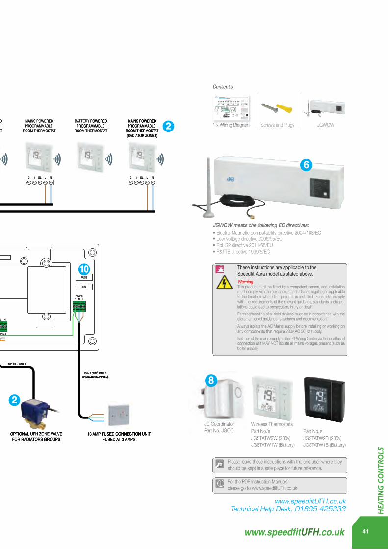
SL L N12 SL L N12 SL L N12SL L N12
LIVE I
N
LIVE O
UT
FUSE
FUSE
ACTUATOR CABLES
230V TO UFH PUMP
UNDERFLOOR HEATING MANIFOLD
1.5MM2 CABLE (INSTALLER SUPPLIED)
230V 1.5MM2 CABLE(INSTALLER SUPPLIED)
230V 1.5MM2 CABLE(INSTALLER SUPPLIED)
230V 1.5MM2 CABLE(INSTALLER SUPPLIED)
230V 1.5MM2 CABLE(INSTALLER SUPPLIED)
13 AMP FUSED CONNECTION UNITFUSED AT 3 AMPS
OPTIONAL CYLINDER STAT
OPTIONAL WIRELESS RECEIVER
PART NO. JGBR
OPTION 1
OPTION 2
LIVE I
N
LIVE O
UT
ZONE 1 ZONE 2
HW CYLINDERTHERMOSTAT
HW MOTORISED VALVE
UFH MOTORISED VALVE
OVERHEAT STAT
IN OUT IN OUT IN OUTBR EA N NL EOR GR BR EA N OR GRUFH PUMP BOILER
ENABLE
ZONE 3 ZONE 4 ZONE 5 ZONE 6 ZONE 7
SL L N12
L N L N L N L N L N L N
THERMOSTAT NEUTRAL CONNECTIONS THERMOSTAT LIVE CONNECTIONS
L N L N L N L N L N L N L N L N
MAINS POWEREDHOT WATER TIMER
BATTERY POWEREDPROGRAMMABLE
ROOM THERMOSTAT
MAINS POWEREDPROGRAMMABLE
ROOM THERMOSTAT
BATTERY POWEREDPROGRAMMABLE
ROOM THERMOSTAT
MAINS POWEREDPROGRAMMABLE
ROOM THERMOSTAT
BATTERY POWEREDPROGRAMMABLE
ROOM THERMOSTAT
MAINS POWEREDPROGRAMMABLE
ROOM THERMOSTAT
BATTERY POWEREDPROGRAMMABLE
ROOM THERMOSTAT
MAINS POWEREDPROGRAMMABLE
ROOM THERMOSTAT(RADIATOR ZONES)
1
2
74
59
10
FACTORY FITTED
LINK
FACTORY FITTED
LINK 3
SUPPLIED CABLE
OPTIONAL UFH ZONE VALVEFOR RADIATORS GROUPS
ZONE 8
L N L N
2
230V 1.5MM2 CABLE(INSTALLER SUPPLIED)
COLOURS ARE INDICATIVE ONLY. EXTRA CONNECTIONS MAY BE REQUIRED AS PER
MANUFACTURERS INSTRUCTIONS.EARTH AS REQUIRED.
POWERE N L
TIMERTER AATER WHOTMAINS POWERED
ROOM THERMOST
PROGRAMMABLE POWEREDYTTERBAATTER
TIMERMAINS POWERED
ROOM THERMOST
PROGRAMMABLE MAINS POWERED
TAAT RMOST PROGRAMMABLE
POWERED
ROOM THERMOST
PROGRAMMABLE TTERBAATTER
TAATROOM THERMOSTPROGRAMMABLE MAINS POWERED
ROOM THERMOST
PROGRAMMABLE MAINS POWERED
TAATROOM THERMOSTPROGRAMMABLE
POWEREDYTTER
TAATOM THERMOST TA
PROGRAMMABLE MAINS POWERED
TAATROOM THERMOST
PROGRAMMABLE POWEREDYTTERBAATTER
TAATROOM THERMOST
PROGRAMMABLE MAINS POWERED
ROOM THERMOST
PROGRAMMABLE POWEREDYTTERBAAT
OR ZONES)T(RADIAATROOM THERMOST
PROGRAMMABLE MAINS POWERED
TAAT T TPROGRAMMABLE
POWERED
OR ZONES)TAATROOM THERMOST
PROGRAMMABLE MAINS POWERED 2
2 1 LSL
N
2 1 SL
NLSL
2
1 NLSL
2 1 NLSL
2 1 LSL
N
OPTION 2
OPTION 11
ALLER SUPPLIED)(INST2230V 1.5MM
ALLER SUPPLIED)CABLE
ALLER SUPPLIED)(INSTCABLE2230V 1.5MM
ALLER SUPPLIED)(INST230V 1.5MM
LIVE O
UT
LIVE I
N
ALLER SUPPLIED)CABLE2230V 1.5MM
LIVE O
UT
REQUIRED.TH AS EARACTURERS INSTRUCMANUFF
AS PER BE REQUIRED YY BE REQUIRED MA CONNECTIO . EXTRA A CONNECTIONS YY. EXTRAONL
T INDICAATIVE COLOURS ARE ALLER SUPPLIED)(INST
CABLE2230V 1.5MM
REQUIRED.ACTURERS INSTRUCTIONS.
AS PER CONNECTIONS
TIVE ALLER SUPPLIED)
GRORNEABROUTINOVERHEA
ELVVAORISED HW MOT
TAATTHERMOSTTHW CYLINDER
7 F
ENABLEBOILERUFH PUMP
NEABREL N OUTINOUTIN
TATSTOVERHEAAT
LVVAUFH MOT
LINKFITTED
Y RTOCAF
GROR
ELVORISED
4LINK
FITTED Y RTOCAF
3
FUSE
10
LIVE O
UT
LIVE I
N
NLNL9
NEUTRALTAATTHERMOST
NLNLNLNL
5
NLNLNLNL
LIVE CONNECTIONSTAATTHERMOST CONNECTIONS RAL L CONNECTIONS
NLNLNLNL
LIVE CONNECTIONS
NLNL
FUSE
LNEPOWER
CYLI OPTIONAL
TAATINDER ST TAOPTIONAL
ZONE 1
ZONE 3ZONE 2
ZONE 5ZONE 4
ZONE 7ZONE 6
SUPPLIED CABLE
ZONE 8
SUPPLIED CABLE
ALLER SUPPLIED)(INSTCABLE2230V 1.5MM
ALLER SUPPLIED)CABLE
NO. JGBRTARP
OR CABLESTACTUAT
2
ALLER SUPPLIED)(INST
ALLER SUPPLIED)
UNDERFLOOR HEA
TING MANIFOLDNDERFLOOR HEA A
TING MANIFOLD
OPTIONAL
ORS GROUPSTFOR RADIAVALL UFH ZONE V VALOPTIONALL UFH ZONE V
FUSED A FUSED CONNECTION UNITAMP13
ORS GROUPSVE
3 AMPSTFUSED A AT FUSED CONNECTION UNIT
FUSED CONNECTION UNIT
21.5MM
230V
ALLER SUPPLIED)(INSTCABLE2
O UFH PUMPT230V
JGWCW meets the following EC directives:• Electro-Magnetic compatability directive 2004/108/EC• Low voltage directive 2006/95/EC• RoHS2 directive 2011/65/EU• R&TTE directive 1999/5/EC
1 x Wiring Diagram Screws and Plugs JGWCW
Contents
Please note: The information below displays a typical installation for illustration purposes only.
JG Coordinator Part No. JGCO
Wireless ThermostatsPart No.’s JGSTATW2W (230v)JGSTATW1W (Battery)
Part No.’s JGSTATW2B (230v)JGSTATW1B (Battery)
See Thermostat Instruction Manual for grouping options.SL L N12 SL L N12 SL L N12SL L N12
LIVE I
N
LIVE O
UT
FUSE
FUSE
ACTUATOR CABLES
230V TO UFH PUMP
UNDERFLOOR HEATING MANIFOLD
1.5MM2 CABLE (INSTALLER SUPPLIED)
230V 1.5MM2 CABLE(INSTALLER SUPPLIED)
230V 1.5MM2 CABLE(INSTALLER SUPPLIED)
230V 1.5MM2 CABLE(INSTALLER SUPPLIED)
230V 1.5MM2 CABLE(INSTALLER SUPPLIED)
13 AMP FUSED CONNECTION UNITFUSED AT 3 AMPS
OPTIONAL CYLINDER STAT
OPTIONAL WIRELESS RECEIVER
PART NO. JGBR
OPTION 1
OPTION 2
LIVE I
N
LIVE O
UT
ZONE 1 ZONE 2
HW CYLINDERTHERMOSTAT
HW MOTORISED VALVE
UFH MOTORISED VALVE
OVERHEAT STAT
IN OUT IN OUT IN OUTBR EA N NL EOR GR BR EA N OR GRUFH PUMP BOILER
ENABLE
ZONE 3 ZONE 4 ZONE 5 ZONE 6 ZONE 7
SL L N12
L N L N L N L N L N L N
THERMOSTAT NEUTRAL CONNECTIONS THERMOSTAT LIVE CONNECTIONS
L N L N L N L N L N L N L N L N
MAINS POWEREDHOT WATER TIMER
BATTERY POWEREDPROGRAMMABLE
ROOM THERMOSTAT
MAINS POWEREDPROGRAMMABLE
ROOM THERMOSTAT
BATTERY POWEREDPROGRAMMABLE
ROOM THERMOSTAT
MAINS POWEREDPROGRAMMABLE
ROOM THERMOSTAT
BATTERY POWEREDPROGRAMMABLE
ROOM THERMOSTAT
MAINS POWEREDPROGRAMMABLE
ROOM THERMOSTAT
BATTERY POWEREDPROGRAMMABLE
ROOM THERMOSTAT
MAINS POWEREDPROGRAMMABLE
ROOM THERMOSTAT(RADIATOR ZONES)
1
2
74
59
10
FACTORY FITTED
LINK
FACTORY FITTED
LINK 3
SUPPLIED CABLE
OPTIONAL UFH ZONE VALVEFOR RADIATORS GROUPS
ZONE 8
L N L N
2
230V 1.5MM2 CABLE(INSTALLER SUPPLIED)
COLOURS ARE INDICATIVE ONLY. EXTRA CONNECTIONS MAY BE REQUIRED AS PER
MANUFACTURERS INSTRUCTIONS.EARTH AS REQUIRED.
POWERE N L
TIMERTER AA WHOTMAINS POWERED
ROOM THERMOST
PROGRAMMABLE POWEREDYTTERBAA
TIMERMAINS POWERED
ROOM THERMOST
PROGRAMMABLE MAINS POWERED
TA MOST TAPROGRAMMABLE
POWERED
ROOM THERMOST
PROGRAMMABLE TTERBAA
TAAROOM THERMOSTPROGRAMMABLE MAINS POWERED
ROOM THERMOST
PROGRAMMABLE MAINS POWERED
TAAROOM THERMOSTPROGRAMMABLE
POWEREDYTTER
TAAM THERMOST
PROGRAMMABLE MAINS POWERED
TAAROOM THERMOST
PROGRAMMABLE POWEREDYTTERBAT
TAAROOM THERMOST
PROGRAMMABLE MAINS POWERED
ROOM THERMOST
PROGRAMMABLE POWEREDYTTERBAA
OR ZONES)T(RADIAAROOM THERMOST
PROGRAMMABLE MAINS POWERED
TAA T TAPROGRAMMABLE
POWERED
OR ZONES)TAAROOM THERMOST
PROGRAMMABLE MAINS POWERED 2
2 1 LSL
N
2 1 SL
NLSL
2
1 NLSL
2 1 NLSL
2 1 LSL
N
OPTION 2
OPTION 11
ALLER SUPPLIED)(INST2230V 1.5MM
ALLER SUPPLIED)CABLE
ALLER SUPPLIED)(INSTCABLE2230V 1.5MM
ALLER SUPPLIED)(INST230V 1.5MM
LIVE O
UT
LIVE I
N
ALLER SUPPLIED)CABLE2230V 1.5MM
LIVE O
UT
REQUIRED.TH AS EARACTURERS INSTRUCMANUF
AS PER BE REQUIRED YMA CONNECTIO . EXTRA A YY. EXTRAONL
T INDICAAT COLOURS ARE ALLER SUPPLIED)(INST
CABLE2230V 1.5MM
REQUIRED.ACTURERS INSTRUCTIONS.
AS PER CONNECTIONS
TIVE ALLER SUPPLIED)
GRORNEABROUTINOVERHEA
ELVVAORISED HW MOT
TAATTHERMOSTHW CYLINDER
7 F
ENABLEBOILERUFH PUMP
NEABREL N OUTINOUTIN
TATSTOVERHEAA
LVVAUFH MOT
LINKFITTED
Y RTOCAF
GROR
ELVORISED
4LINK
FITTED Y RTOCAF
3
FUSE
10
LIVE O
UT
LIVE I
N
NLNL9
NEUTRALTATHERMOST
NLNLNLNL
5
NLNLNLNL
LIVE CONNECTIONSTAATTHERMOST CONNECTIONS RAL
NLNLNLNL
LIVE CONNECTIONS
NLNL
FUSE
LNEPOWER
CYL OPTIONAL
TATINDER ST TAOPTIONAL
ZONE 1
ZONE 3ZONE 2
ZONE 5ZONE 4
ZONE 7ZONE 6
SUPPLIED CABLE
ZONE 8
SUPPLIED CABLE
ALLER SUPPLIED)(INSTCABLE2230V 1.5MM
ALLER SUPPLIED)CABLE
NO. JGBRTARP
OR CABLESTACTUAT
2
ALLER SUPPLIED)(INST
ALLER SUPPLIED)
UNDERFLOOR HEA
TING NDERFLOOR HEA A
TING MANIFOLD
OPTIONAL
ORS GROUPSTFOR RADIAVAL UFH ZONE V VAOPTIONAL
FUSED A FUSED CONNECTION UNITAMP13
ORS GROUPSVE
3 AMPSTFUSED A FUSED CONNECTION UNIT
FUSED CONNECTION UNIT
21.5MM
230V
ALLER SUPPLIED)(INSTCABLE2
O UFH PUMPT230V
JGWCW meets the following EC directives:• Electro-Magnetic compatability directive 2004/108/EC• Low voltage directive 2006/95/EC• RoHS2 directive 2011/65/EU• R&TTE directive 1999/5/EC
1 x Wiring Diagram Screws and Plugs JGWCW
Contents
Please note: The information below displays a typical installation for illustration purposes only.
JG Coordinator Part No. JGCO
Wireless ThermostatsPart No.’s JGSTATW2W (230v)JGSTATW1W (Battery)
Part No.’s JGSTATW2B (230v)JGSTATW1B (Battery)
See Thermostat Instruction Manual for grouping options.
Please leave these instructions with the end user where theyshould be kept in a safe place for future reference.
For the PDF Instruction Manuals please go to www.speedfitUFH.co.uk
These instructions are applicable to the Speedfit Aura model as stated above.WarningThis product must be fitted by a competent person, and installationmust comply with the guidance, standards and regulations applicableto the location where the product is installed. Failure to complywith the requirements of the relevant guidance, standards and regu-lations could lead to prosecution, injury or death.
Earthing/bonding of all field devices must be in accordance with theaforementioned guidance, standards and documentation.
Always isolate the AC Mains supply before installing or working onany components that require 230v AC 50Hz supply.
Isolation of the mains supply to the JG Wiring Centre via the local fusedconnection unit MAY NOT isolate all mains voltages present (such asboiler enable).
Wiring Diagram and Instruction Manual
JGWCW - Wireless 8 Zone Wiring Centre
www.speedfitUFH.co.ukTechnical Help Desk: 01895 425333
Please leave these instructions with the end user where theyshould be kept in a safe place for future reference.
For the PDF Instruction Manuals please go to www.speedfitUFH.co.uk
These instructions are applicable to the Speedfit Aura model as stated above.WarningThis product must be fitted by a competent person, and installationmust comply with the guidance, standards and regulations applicableto the location where the product is installed. Failure to complywith the requirements of the relevant guidance, standards and regu-lations could lead to prosecution, injury or death.
Earthing/bonding of all field devices must be in accordance with theaforementioned guidance, standards and documentation.
Always isolate the AC Mains supply before installing or working onany components that require 230v AC 50Hz supply.
Isolation of the mains supply to the JG Wiring Centre via the local fusedconnection unit MAY NOT isolate all mains voltages present (such asboiler enable).
Wiring Diagram and Instruction Manual
JGWCW - Wireless 8 Zone Wiring CentreZ2105/413/1114
www.speedfitUFH.co.ukTechnical Help Desk: 01895 425333
JG Wiring Diagram (Wireless) 500x353 Z2105-413-1114_Layout 1 25/11/2014 12:01 Page 1
HEA
TIN
G C
ON
TRO
LS
41www.speedfitUFH.co.uk
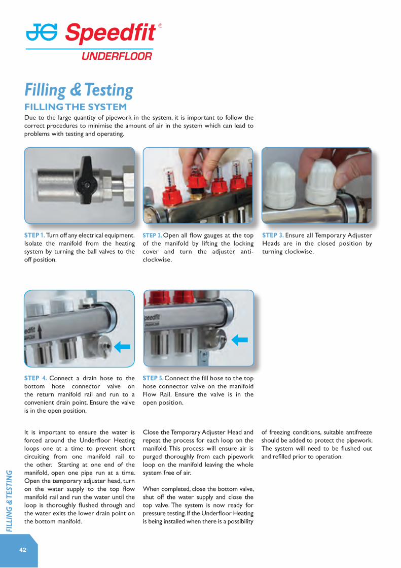
STEP 1. Turn off any electrical equipment.Isolate the manifold from the heating system by turning the ball valves to the off position.
Due to the large quantity of pipework in the system, it is important to follow the correct procedures to minimise the amount of air in the system which can lead to problems with testing and operating.
STEP 4. Connect a drain hose to the bottom hose connector valve on the return manifold rail and run to a convenient drain point. Ensure the valve is in the open position.
STEP 3. Ensure all Temporary Adjuster Heads are in the closed position by turning clockwise.
STEP 2. Open all flow gauges at the top of the manifold by lifting the locking cover and turn the adjuster anti-clockwise.
STEP 5. Connect the fill hose to the top hose connector valve on the manifold Flow Rail. Ensure the valve is in the open position.
It is important to ensure the water is forced around the Underfloor Heating loops one at a time to prevent short circuiting from one manifold rail to the other. Starting at one end of the manifold, open one pipe run at a time. Open the temporary adjuster head, turn on the water supply to the top flow manifold rail and run the water until the loop is thoroughly flushed through and the water exits the lower drain point on the bottom manifold.
Close the Temporary Adjuster Head and repeat the process for each loop on the manifold. This process will ensure air is purged thoroughly from each pipework loop on the manifold leaving the whole system free of air.
When completed, close the bottom valve, shut off the water supply and close the top valve. The system is now ready for pressure testing. If the Underfloor Heating is being installed when there is a possibility
of freezing conditions, suitable antifreeze should be added to protect the pipework. The system will need to be flushed out and refilled prior to operation.
42
FILLING THE SYSTEM
Filling & Testing
FILL
ING
& T
ESTI
NG

STEP 1. Turn off any electrical equipment.Isolate the manifold from the heating system by turning the ball valves to the off position.
Once the system has been filled a hydraulic pressure test should be carried out on all loops in the system prior to the installation of floor coverings. (JG Speedfit do not recommend air testing of pipework).
STEP 4. Connect a suitable pressure testing kit to one of the fill valves. With the valve open, pump up the pressure to 2 Bar. Isolate the pressure at the tester and leave for 10mins while checking for leaks or pressure drops.
STEP 3. Ensure all Temporary Adjuster Heads are in the open position by turning the Adjustor Heads anti-clockwise.
STEP 2. Open all flow gauges at the top of the manifold by lifting the locking cover and turning the adjuster anti-clockwise.
STEP 5. If all is well, increase the pressure to 10 bar and leave for a further 10 minutes while checking for leaks or pressure drops.
STEP 6. If all remains well, reduce pressure to operating pressure. For screeded floors, pipework should be left to approxiamately 3-6 bar until the screed has been laid and dried to protect pipework from damage. Consult screed supplier for drying out and curing time.
43www.speedfitUFH.co.uk
TESTING THE SYSTEM
FILL
ING
& T
ESTI
NG

STEP 1. ELECTRICAL SAFETY CHECK Confirm that the system wiring is in accordance with the current Electrical Wiring Regulations.
STEP 5. GAUGE AND VALVE CHECKS
Check & adjust flow gauge function & confirm that all circuit valves are open and that any flowmeters are registering a positive flowrate.
STEP 4. CHECK ROOMSTAT & ACTUATOR FUNCTION & CONTROLS FUNCTION Room thermostats should be set to call for heat and confirmed to be operating the Circuit Actuator Heads on the Manifold(s). There will be a delay of up to 2 minutes before the actuators are fully open.
STEP 3. INITIAL START UP The temperature control on the JG Control or JG Roompack should initially be set down to the lowest possible setting (25-30°C).
STEP 7. System response will be slow on initial start up. When the system has been operating for an hour, check the return pipe temperatures where pipe is rising out of the floor back to the manifold. Ensure that all loops are open and operating, there will be a temperature difference of 8°C. Confirm with JG designs for specific temperature information.
STEP 2. SYSTEM CHECK Ensure the system is filled, leak free, vented and has been pressure tested. Ensure all isolator valves are open, automatic valves are functional, and the circulator pump is in working order before switching on.
STEP 6. FLOW AND TEMPERATURE CHECKS
Check there is sufficient flow & temperature supply from the heat source to the manifold.
The warm up procedure should be carried out using natural infiltration and after switching-off all other heating. All external doors and windows should be closed.
44
SCREED DRYING/CURING FOR SCREEDED FLOORSTo prevent damage by cracking, curling, expansion or shrinkage effects, new floor screeds require careful preheating before commissioning can take place.
Most screeded floors require 28 days after laying before preheating can begin, however, Calcium Sulphate screeds may need only 7 days after laying (check with manufacturer for specific drying times).
The Underfloor Heating should not be used during this time period and under no circumstances should it be used to accelerate the drying period.
Start-up & Commissioning
Blue disk in actuator will rise to show valve is open. The actuator comes partly open from factory to assist with initial assembly.
STAR
T-U
P &
CO
MM
ISSI
ON
ING
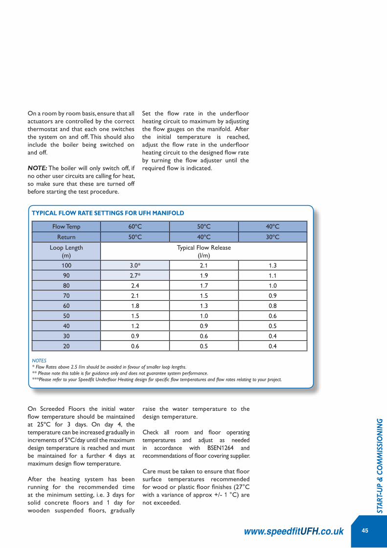
45www.speedfitUFH.co.uk
TYPICAL FLOW RATE SETTINGS FOR UFH MANIFOLD
NOTES* Flow Rates above 2.5 l/m should be avoided in favour of smaller loop lengths.** Please note this table is for guidance only and does not guarantee system performance.***Please refer to your Speedfit Underfloor Heating design for specific flow temperatures and flow rates relating to your project.
On Screeded Floors the initial water flow temperature should be maintained at 25ºC for 3 days. On day 4, the temperature can be increased gradually in increments of 5ºC/day until the maximum design temperature is reached and must be maintained for a further 4 days at maximum design flow temperature.
After the heating system has been running for the recommended time at the minimum setting, i.e. 3 days for solid concrete floors and 1 day for wooden suspended floors, gradually
raise the water temperature to the design temperature.
Check all room and floor operating temperatures and adjust as needed in accordance with BSEN1264 and recommendations of floor covering supplier.
Care must be taken to ensure that floor surface temperatures recommended for wood or plastic floor finishes (27°C with a variance of approx +/- 1 °C) are not exceeded.
Flow Temp 60ºC 50ºC 40ºC
Return 50ºC 40ºC 30ºC
Loop Length(m)
Typical Flow Release(l/m)
100 3.0* 2.1 1.3
90 2.7* 1.9 1.180 2.4 1.7 1.0
70 2.1 1.5 0.9
60 1.8 1.3 0.8
50 1.5 1.0 0.6
40 1.2 0.9 0.5
30 0.9 0.6 0.4
20 0.6 0.5 0.4
On a room by room basis, ensure that all actuators are controlled by the correct thermostat and that each one switches the system on and off. This should also include the boiler being switched on and off.
NOTE: The boiler will only switch off, if no other user circuits are calling for heat, so make sure that these are turned off before starting the test procedure.
Set the flow rate in the underfloor heating circuit to maximum by adjusting the flow gauges on the manifold. After the initial temperature is reached, adjust the flow rate in the underfloor heating circuit to the designed flow rate by turning the flow adjuster until the required flow is indicated.
STAR
T-U
P &
CO
MM
ISSI
ON
ING
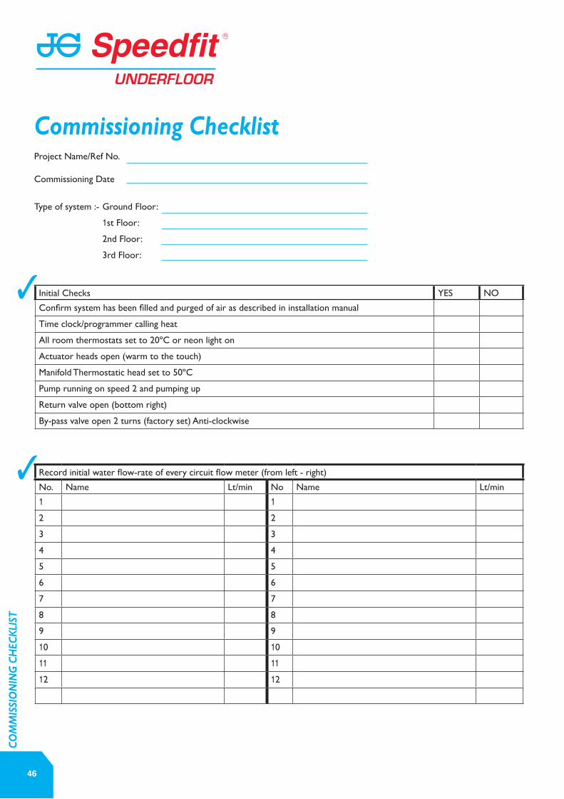
Project Name/Ref No.
Commissioning Date
Type of system :- Ground Floor:
1st Floor:
2nd Floor:
3rd Floor:
Initial Checks YES NO
Confirm system has been filled and purged of air as described in installation manual
Time clock/programmer calling heat
All room thermostats set to 20ºC or neon light on
Actuator heads open (warm to the touch)
Manifold Thermostatic head set to 50ºC
Pump running on speed 2 and pumping up
Return valve open (bottom right)
By-pass valve open 2 turns (factory set) Anti-clockwise
Record initial water flow-rate of every circuit flow meter (from left - right)
No. Name Lt/min No Name Lt/min
1 12 2
3 3
4 4
5 5
6 6
7 7
8 8
9 9
10 10
11 1112 12
46
Commissioning Checklist
3
3
CO
MM
ISSI
ON
ING
CH
ECKL
IST
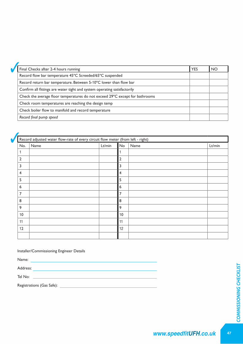
Final Checks after 2-4 hours running YES NO
Record flow bar temperature 45ºC Screeded/65ºC suspended
Record return bar temperature. Between 5-10ºC lower than flow bar
Confirm all fittings are water tight and system operating satisfactorily
Check the average floor temperatures do not exceed 29ºC except for bathrooms
Check room temperatures are reaching the design temp
Check boiler flow to manifold and record temperature
Record final pump speed
Record adjusted water flow-rate of every circuit flow meter (from left - right)
No. Name Lt/min No Name Lt/min
1 12 2
3 3
4 4
5 5
6 6
7 7
8 8
9 9
10 10
11 1112 12
Installer/Commissioning Engineer Details
Name:
Address:
Tel No:
Registrations (Gas Safe):
47www.speedfitUFH.co.uk
3
3
CO
MM
ISSI
ON
ING
CH
ECKL
IST

48
HOW LONG DOES UNDERFLOOR HEATING TAKE TO WARM UP A ROOM FROM COLD?In high mass systems such as some screed floors the system can take 2 - 3 hours to heat up from cold.
After an initial heat up advanced controls maintain the screed temperature and with a process known as set back, reduces the room temperature by approx 4°C during periods of low demand such as overnight, allowing for a quicker heat up time the following morning.
HOW MUCH HEAT WILL MY UNDERFLOOR HEATING SYSTEM PROVIDE?Typically, a screeded floor will emit a maximum of 100w/sqm. Timber floor structure will emit a maximum of 70w/ sqm.
WHAT FLOOR AREA CAN A MANIFOLD HEAT?Manifolds are available to cater from 2 to 12 zones.
A 12 zone manifold, feeding 12 heating loops can serve between 120 and 150 sqm of floor area. For larger systems use more than one manifold.
HOW LONG DO I LEAVE MY UNDERFLOOR HEATING ON FOR DURING THE DAY?Underfloor Heating is at its most efficient if left on 24 hours a day using room thermostats to control the comfort levels in each space or zone.
Timers and programmers allow the user to choose when the heating is on or off or when to tell the system to reduce average temperature overnight, for example, known as set back.
This saves energy and gives a faster heat up time the following morning.
CAN I JOIN PIPES IN THE FLOOR?No, pipes must not be joined in the floor.
HOW MUCH WATER WILL BE IN MY SYSTEM?Speedfit manufacture a 15mm pipe for use with underfloor heating. Every 1m of pipe contains 0.1L of water.
HOW MUCH PIPE DO I NEED?In a typical installation, pipe is laid at 200mm centres. This equates to approx 5 metres per sqmLoops should be no longer than 100m. Speedfit will calculate the pipe spacing and loop lengths for each room or zone to meet the heat requirements of the space.
WHAT IS EDGE INSULATION USED FOR?Edge insulation is very important and is used on screeded floor systems.
It creates an insulation barrier around the perimeter of a room to prevent lateral heat loss and provides an expansion gap for the solid floor as it heats up and cools down.
Speedfit Edge insulation can also be used as an expansion medium on areas of screeded floor in excess of 40 sqm.
WHAT TYPE OF SCREED SHOULD I USE?Most screeds are a traditional sand and cement mix of 65 - 75 mm in thickness. Additives and binding agents are also used for added strength and flexibility.
Thinner screeds of 40 - 50 mm often known as pumped or liquid screeds are available. These offer better response times for underfloor heating and quicker drying time.
Specific advice should be sought from the screed manufacturer who will specify the correct screed for your project.
DO I NEED TO ADD INHIBITORS TO THE SYSTEM?Yes, Speedfit advise that inhibitors should be used in all central heating systems including underfloor systems. Fernox and Betz Dearborn manufacture suitable products.
WHERE SHOULD THE MANIFOLD BE POSITIONED?The underfloor heating manifold can be located anywhere. However, to reduce pipe runs and achieve a balanced system it is preferable to locate the manifold as near as possible to the centre of the building.
WHAT FLOOR COVERINGS CAN BE USED WITH UNDERFLOOR HEATING?Almost all floor coverings will work with underfloor heating including carpets, stone tiles, laminate and natural wood. This gives you a virtually unlimited choice. All materials have
a resistance to heat transfer and this can be expressed as a TOG value - the same as for a duvet.
BSEN1264 states that floor coverings should be no greater than 1.5 TOGs.
However, experience has shown that many carpet and underlay combinations with high resistance work with underfloor heating.
Always ask the floor covering supplier if a their products are suitable for use with underfloor heating.
HOW MUCH INSULATION DO I NEED?The amount of insulation within a building is very important for an underfloor heating.
A layer of insulation should be placed immediately below the heating pipes to minimise the downward heat loss of the floor and maximise the heat emitted upwards.
The total amount of insulation required is calculated in 2 parts. Firstly, the architect will specify the type and depth of installation to comply with the Building Regulations.
WHAT GUARANTEES DO SPEEDFIT GIVE?As a result of long term test programmes and rigorous quality standards, John Guest Speedfit Limited offer a 25 year guarantee against the defects in materials or manufacturing of “PEM” “PSE” and “SFM” Range Plumbing Fittings and Speedfit Barrier Pipe manufactured by John Guest.
John Guest Underfloor Heating Products, which should be installed and maintained in accordance with our recommendations, carry a 2 year guarantee against defects in materials and manufacture.
John Guest Plumbing and Heating Products are for use with normal UK domestic plumbing and heating systems and are supplied in accordance with our Conditions of Sales.
Frequently Asked Questions
FREQ
UEN
TLY
ASKE
D Q
UES
TIO
NS
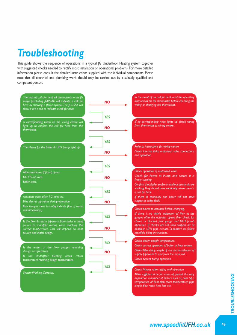
49www.speedfitUFH.co.uk
Troubleshooting
YES
YES
YES
YES
YES
YES
YES
NO
NO
NO
NO
NO
NO
NO
TRO
UBL
ESH
OO
TIN
G
This guide shows the sequence of operations in a typical JG Underfloor Heating system together with suggested checks needed to rectify most installation or operational problems. For more detailed information please consult the detailed instructions supplied with the individual components. Please note that all electrical and plumbing work should only be carried out by a suitably qualified and competent person.
Thermostat calls for heat, all thermostats in the JG range (excluding JGDSSB) will indicate a call for heat by showing a flame symbol. The JGDSSB will show a red neon to indicate a call for heat.
In the event of no call for heat, read the operating instructions for the thermostat before checking the wiring or changing the thermostat.
A corresponding Neon on the wiring centre will light up to confirm the call for heat from the thermostat.
If no corresponding neon lights up check wiring from thermostat to wiring centre.
The Neons for the Boiler & UFH pump light up. Refer to instructions for wiring centre.
Check internal links, motorized valve connections and operation.
Motorised Valve, if fitted, opens.
UFH Pump runs.
Boiler start.
Check operation of motorised valve.
Check for Power at Pump and ensure it is freely turning.
Confirm that Boiler enable in and out terminals are working. They should have continuity when there is a call for heat.
If there is continuity and boiler will not start suspect a boiler fault.
Actuators open after 1-2 minutes.
Blue disc at top raises during operation.
Flow Gauges move to visibly indicate flow of water around circuit(s). Check power to actuator before changing.
If there is no visible indication of flow at the gauges after the actuator opens then check for closed or blocked flow gauge and UFH pump operation. If checks are OK then suspect air or debris in UFH pipe circuits. To remove air follow manifold filling instructions.
Is the flow & return pipework from boiler or heat source to manifold mixing valve reaching the correct temperature. This will depend on heat source and initial design.
Check design supply temperature.
Check correct operation of boiler or heat source.
Check Pipe sizing length of run and installation of supply pipework to and from the manifold.
Check system pump operation.
Is the water at the flow gauges reaching design temperature.
Is the Underfloor Heating circuit return temperature reaching design temperature.
Check Mixing valve setting and operation.
Allow sufficient time for warm up period, this may depend on a number of factors such as; floor type, temperature of floor slab, room temperature, pipe length, flow rates, heat loss etc.
System Working Correctly.
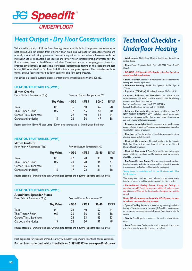
50
Technical Checklist - Underfloor Heating• Applications. Underfloor Heating Installations in solid or timber floors.
• Pipes. 15mm JG Speedfit Barrier Pipe to BS 7291, Parts 1, 2 and 3 Class S.
• DO NOT USE Speedfit UFH Products for Gas, fuel oil or compressed air applications.
• Floor Insulation. Should be a suitable material and thickness to comply with current regulations.• Minimum Bending Radii. For Speedfit B-PEX Pipe is 175mm. • Expansion (PEX - Pipe). 1% on length between 20˚C and 82˚C.
• Cleaners, Inhibitors and Descalents. For advice on the replenishment of additives such as corrosion inhibitors, the following manufacturers should be contacted: Fernox Manufacturing Limited on 01799 550811 or Sentinel, BetzDearborn Limited on 0151420 9595.
• Paint and Chemicals. Only use water or oil based paint. DO NOT ALLOW CONTACT WITH cellulose based paints, paint thinners or strippers, solder flux or acid based descalents or aggressive household cleaning products.
• Exposure to sunlight. Speedfit products, when used indoors, are not affected by sunlight. When used out doors protect from ultra violet light by lagging or painting.
• Pipe Inserts. Must be used on all installations when using plastic pipe and should be fully inserted.
• Electrical Components. Electrical products in the Speedfit Underfloor Heating System are designed only to be used in U.K. Electrical Supply situations.
• Electrical Continuity. If Speedfit is used in an existing metal system which may have been used for earthing, electrical continuity should be reinstated.
• Pre-Screed System Testing. To ensure the pipework has been installed correctly and prior to the screed being laid, it is essential that the system is checked and hydraulically wet tested.
Testing should be carried out at 2 bar for 10 minutes and 10 bar for 10 minutes.
This testing, combined with other relevant checks, should reveal installation problems and is regarded as good plumbing practice.
• Pressurisation During Screed Laying & Curing. In accordance with BS1264-4, the system should be left under pressure at a minimum of 6 bar for the duration of the laying and curing of the screed.
Under NO circumstances should the UFH System be used to quicken the screed drying process.
• System Flushing. As is usual practice for any plumbing installation, flushing of the system prior to the use of JG Speedfit is recommended to remove any contaminants/chemical residue from elsewhere in the system.
• Vermin. Speedfit products should not be used in vermin infested areas.
• Frost Protection. During the installation process it is important that pipe containing water be protected from frost.
Heat Output - Dry Floor ConstructionsWith a wide variety of Underfloor heating systems available, it is important to know what heat output you can expect from differing floor make ups. Outputs for Screeded systems are normally calculated using proven mathematical equations and experience. However, with the increasing use of renewable heat sources and lower water temperatures, performace for dry floor constructions can be difficult to calculate. Therefore, due to our ongoing commitment to product development, Speedfit have conducted performance testing at the independent test house , BSRIA for the Overfit, Underfit & Aluminium Heat plates systems. The tables below show typical output figures for various floor coverings and flow temperatures. For advice on specific systems please contact our technical helpline 01895 425333.
Figures based on 15mm PB tube using 150mm pipe centres and a 10mm Plywood laid over.
Figures based on 15mm PB tube using 200mm pipe centres and a 22mm chipboard deck laid over.
Figures based on 15mm PB tube using 200mm pipe centres and a 22mm chipboard deck laid over.
Heat ouputs are for guidance only and can vary with water temperature, floor finish and construction. Further information and advice is available on 01895 425333 or www.speedfitufh.co.uk
25mm Overfit - Floor Finish + Resistance (Tog) Flow and Return Temperature oC Tog Value 40/30 45/35 50/40 55/45
Tiles 0.1 36 50 65 78Thin Timber Finish 0.5 32 45 58 70Carpet Tiles / Laminate 1 29 40 52 64Carpet and underlay 1.5 26 36 47 58
50mm UnderfitFloor Finish + Resistance (Tog) Flow and Return Temperature oC
Tog Value 40/30 45/35 50/40 55/45
Tiles 0.1 22 20 39 48Thin Timber Finish 0.5 20 28 36 44Carpet Tiles / Laminate 1 18 26 33 41Carpet and underlay 1.5 17 22 31 38
Aluminium Spreader PlatesFloor Finish + Resistance (Tog) Flow and Return Temperature oC
Tog Value 40/30 45/35 50/40 55/45
Tiles 0.1 28 40 52 64Thin Timber Finish 0.5 26 36 47 58Carpet Tiles / Laminate 1 24 33 43 53Carpet and underlay 1.5 22 30 39 48
HEAT OUTPUT TABLES (W/M2)
HEAT OUTPUT TABLES (W/M2)
HEAT OUTPUT TABLES (W/M2)

51www.speedfitUFH.co.uk
Notes

John Guest Speedfit Limited
Horton Road, West Drayton, Middlesex UB7 8JL, England.Tel: 01895 449233 Fax: 01895 420321 www.speedfit.co.uk | www.speedfitUFH.co.uk
Technical Help Desk: 01895 425333
The company has a policy of continuous research and development and reserves the right to amend without notice the specification and design of all products illustrated in this catalogue. John Guest Speedfit reserve the right to change the colour and shape of products. Photographs are for illustration purposes only.
Subject to our Terms and Conditions of Sale available on request.
and are registered trademarks of John Guest International Limited © Copyright 2015.
AVAILABLE FROM:
Z2105/387/0315