The Properties of Materials - Princeton Universityassets.press.princeton.edu/chapters/s9638.pdf ·...
23
CHAPTER 1 ................................................. The Properties of Materials FORCES: DYNAMICS AND STATICS We all have some intuitive idea about the mechanics of the world around us, an idea built up largely from our own experience. However, a proper scientifi understanding of mechanics has taken centuries to achieve. Isaac Newton was of course the founder of the science of mechanics; he was the firs to describe and understand the ways in which moving bodies behave. Introducing the concepts of inertia and force, he showed that the behav- ior of moving bodies could be summed up in three laws of motion. 1) The law of inertia: An object in motion will remain in motion unless acted upon by a net force. The inertia of an object is its reluctance to change its motion. 2) The law of acceleration: The acceleration of a body is equal to the force applied to it divided by its mass, as summarized in the equation F = ma, (1.1) where F is the force; m, the mass; and a, the acceleration. 3) The law of reciprocal action: To every action there is an equal and opposite reaction. If one body pushes on another with a given force, the other will push back with the same force in the opposite direction. To summarize with a simple example: if I give a push to a ball that is initially at rest (fig 1.1a), it will accelerate in that direction at a rate proportional to the force and inversely proportional to its mass. The great step forward in Newton’s scheme was that, together with the inverse square law of gravity, it showed that the force that keeps us down on earth is one and the same with the force that directs the motion of the planets. All this is a great help in understanding dynamic situations, such as billiard balls colliding, guns firin bullets, planets circling the sun, or frogs jumping. Unfortunately it is much less useful when it comes to examining what is happening in a range of no-less-common everyday situations. What is happening when a book is lying on a desk, when a light bulb is hanging from the ceiling, or when I am trying to pull a tree over? (See fig 1.1b.) In all of these static situations, it is clear that there is no acceleration (at least until the tree does fall over), so the table or rope must be resisting gravity and the tree must be resisting the forces I am putting on it with equal and opposite Copyrighted Material
Transcript of The Properties of Materials - Princeton Universityassets.press.princeton.edu/chapters/s9638.pdf ·...
July 28, 2011 Time: 10:54am chapter01.tex
CHAPTER 1. . . . . . . . . . . . . . . . . . . . . . . . . . . . . . . . . . . . . . . . . . . . . . . . .
The Properties of Materials
FORCES: DYNAMICS AND STATICS
We all have some intuitive idea about the mechanics of the world aroundus, an idea built up largely from our own experience. However, a properscientifi understanding of mechanics has taken centuries to achieve. IsaacNewton was of course the founder of the science of mechanics; he was thefirs to describe and understand the ways in which moving bodies behave.
Introducing the concepts of inertia and force, he showed that the behav-ior of moving bodies could be summed up in three laws of motion.
1) The law of inertia: An object in motion will remain in motionunless acted upon by a net force. The inertia of an object is itsreluctance to change its motion.
2) The law of acceleration: The acceleration of a body is equal tothe force applied to it divided by its mass, as summarized in theequation
F = ma, (1.1)
where F is the force; m, the mass; and a, the acceleration.3) The law of reciprocal action: To every action there is an equal
and opposite reaction. If one body pushes on another with a givenforce, the other will push back with the same force in the oppositedirection.
To summarize with a simple example: if I give a push to a ball that is initiallyat rest (fig 1.1a), it will accelerate in that direction at a rate proportional tothe force and inversely proportional to its mass. The great step forward inNewton’s scheme was that, together with the inverse square law of gravity, itshowed that the force that keeps us down on earth is one and the same withthe force that directs the motion of the planets.
All this is a great help in understanding dynamic situations, such asbilliard balls colliding, guns firin bullets, planets circling the sun, or frogsjumping. Unfortunately it is much less useful when it comes to examiningwhat is happening in a range of no-less-common everyday situations. Whatis happening when a book is lying on a desk, when a light bulb is hangingfrom the ceiling, or when I am trying to pull a tree over? (See fig 1.1b.) In allof these static situations, it is clear that there is no acceleration (at least untilthe tree does fall over), so the table or rope must be resisting gravity and thetree must be resisting the forces I am putting on it with equal and opposite
Copyrighted Material

July 28, 2011 Time: 10:54am chapter01.tex
4 CHAPTER 1
(a)
F a
F
(b)
m
Figure 1.1. Forces on objects in dynamic and static situations. In dynamic situa-tions, such as a pool ball being given a push with a cue (a), the force, F , results in theacceleration, a, of the ball. In static situations, such as a tree being pulled sidewayswith a rope (b), there is no acceleration.
reactions. But how do objects supply that reaction, seeing as they have noforce-producing muscles to do so? The answer lies within the materialsthemselves.
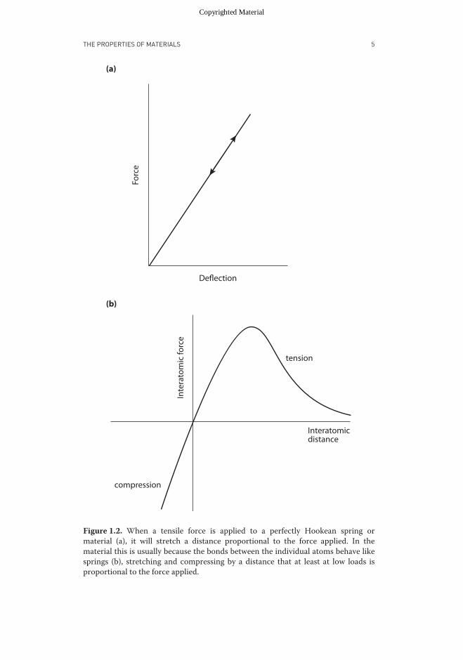
Robert Hooke (1635–1703) was the firs to notice that when springs,and indeed many other structures and pieces of material, are loaded, theychange shape, altering in length by an amount approximately proportionalto the force applied, and that they spring back into their original shape afterthe load is removed (fig 1.2a). This linear relationship between force andextension is known as Hooke’s law.
What we now know is that all solids are made up of atoms. In crystallinematerials, which include not only salt and diamonds but also metals, suchas iron, the atoms are arranged in ordered rows and columns, joined by stiffinteratomic bonds. If these sorts of materials are stretched or compressed,we are actually stretching or compressing the interatomic bonds (fig 1.2b).They have an equilibrium length and strongly resist any such movement. Intypically static situations, therefore, the applied force is not lost or dissipatedor absorbed. Instead, it is opposed by the equal and opposite reaction forcethat results from the tendency of the material that has been deformedto return to its resting shape. No material is totally rigid; even blocks ofthe stiffest materials, such as metals and diamonds, deform when they areloaded. The reason that this deformation was such a hard discovery to makeis that most structures are so rigid that their deflectio is tiny; it is only whenwe use compliant structures such as springs or bend long thin beams that thedeflectio common to all structures is obvious.
The greater the load that is applied, the more the structure is deflecteduntil failure occurs; we will then have exceeded the strength of our structure.In the case of the tree (fig 1.1b), the trunk might break, or its roots pull outof the soil and the tree accelerate sideways and fall over.
INVESTIGATING THE MECHANICAL PROPERTIES OF MATERIALS
The science of elasticity seeks to understand the mechanical behavior ofstructures when they are loaded. It aims to predict just how much they
Copyrighted Material
July 28, 2011 Time: 10:54am chapter01.tex
THE PROPERTIES OF MATERIALS 5
Forc
e
Inte
rato
mic
forc
e
compression
Interatomicdistance
tension
Deflection
(a)
(b)
Figure 1.2. When a tensile force is applied to a perfectly Hookean spring ormaterial (a), it will stretch a distance proportional to the force applied. In thematerial this is usually because the bonds between the individual atoms behave likesprings (b), stretching and compressing by a distance that at least at low loads isproportional to the force applied.
Copyrighted Material

July 28, 2011 Time: 10:54am chapter01.tex
6 CHAPTER 1
(a) (b)Displacement
Stre
ss (σ
)
Strain (ε)
σmax
σyield
εmaxεyield
Figure 1.3. In a tensile test, an elongated piece of a material is gripped at both ends(a) and stretched. The sample is usually cut into a dumbbell shape so that failure doesnot occur around the clamps, where stresses can be concentrated. The result of sucha test is a graph of stress against strain (b), which shows several importantmechanicalproperties of the material. The shaded area under the graph is the amount of elasticenergy the material can store.
should deflec under given loads and exactly when they should break. Thiswill depend upon two things. The properties of the material are clearlyimportant—a rod made of rubber will stretch much more easily than onemade of steel. However, geometry will also affect the behavior: a long, thinlength of rubber will stretch much more easily than a short fat one.
To understand the behavior of materials, therefore, we need to be ableseparate the effects of geometry from those of the material properties. Tosee how this can be done, let us examine the simplest possible case: a tensiletest (fig 1.3a), in which a uniform rod of material, say a rubber band, isstretched.
The Concept of Stress
If it takes a unit force to stretch a rubber band of a given cross-sectionalarea a given distance, it can readily be seen that it will take twice theforce to give the same stretch to two rubber bands set side by side or toa single band of twice the thickness. Resistance to stretching is thereforedirectly proportional to the cross-sectional area of a sample. To determinethe mechanical state of the rubber, the force applied to the sample must
Copyrighted Material

July 28, 2011 Time: 10:54am chapter01.tex
THE PROPERTIES OF MATERIALS 7
consequently be normalized by dividing it by its cross-sectional area. Doingso gives a measurement of the force per unit area, or the intensity of theforce, which is known as stress and which is usually represented by thesymbol σ , so that
σ = P/A, (1.2)
where P is the applied load and A the cross-sectional area of the sam-ple. Stress is expressed in SI units of newtons per square meter (Nm−2)or pascals (Pa). Unfortunately, this unit is inconveniently small, so moststresses are given in kPa (Nm−2 × 10³), MPa (Nm−2 × 10⁶), or even GPa(Nm−2 × 10⁹).
The Concept of Strain
If it takes a unit force to stretch a rubber band of a given length by a givendistance, the same force applied to two rubber bands joined end to end or toa single band of twice the length will result in twice the stretch. Resistanceto stretching is therefore inversely proportional to the length of a sample.To determine the change in shape of the rubber as a material in general,and not just of this sample, the deflectio of the sample must consequentlybe normalized by dividing by its original length. This gives a measure ofhow much the material has stretched relative to its original length, which isknown as strain and which is usually represented by the symbol, ε, so that
ε = dL/L , (1.3)
where dL is the change in length and L the original length of the sample.Strain has no units because it is calculated by dividing one length by another.
It is perhaps unfortunate that engineers have chosen to give the everydaywords stress and strain such precise definition in mechanics, since doingso can confuse communications between engineers and lay people who areused to the vaguer uses of these words. As we shall see, similar confusion canalso be a problem with the terms used to describe the mechanical propertiesof materials.
DETERMINING MATERIAL PROPERTIES
Many material properties can be determined from the results of a tensiletest once the graph of force against displacement has been converted withequations 1.2 and 1.3 into one of stress versus strain. Figure 1.3b shows thestress-strain curve for a typical tough material, such as a metal. Like many,but by no means all, materials, this one obeys Hooke’s law, showing linearelastic behavior: the stress initially increases rapidly in direct proportion tothe strain. Then the material reaches a yield point, after which the stressincreases far more slowly, until finall failure occurs and the material breaks.
Copyrighted Material

July 28, 2011 Time: 10:54am chapter01.tex
8 CHAPTER 1
The f rst important property that can be derived from the graphs is thestiffness of the material, also known as its Young’s modulus, which isrepresented by the symbol E . Stiffness is equal to the initial slope of thestress-strain curve and so is given mathematically by the expression
E = dσ/dε (1.4)
or by the original force-displacement curve
E = LdPAdL
. (1.5)
Stiff materials therefore have a high Young’s modulus. Compliance is theinverse of stiffness, so compliant materials have a low Young’s modulus. Inmany materials, the slope of the curve changes as the material is stretched.For such materials one can distinguish between the initial stiffness and thetangent stiffness, which is the slope at higher strains.
The second important property that can be derived is the strength, orbreaking stress, of the material; this is simply the maximum value of stress,σmax, along the y-axis. Breaking stress can alternatively be calculated fromthe original force-displacement curve using the formula
σmax = Pmax/A. (1.6)
Strong materials have a high breaking stress, whereas weak ones have alow breaking stress. The yield stress, σyield, can also be read off the graph,being the stress at which it stops obeying Hooke’s law and becomes morecompliant; this is the point at which the slope of the graph falls.
A third useful property of a material is its extensibility, or breakingstrain, εmax, which is simply the maximum value of strain along thex-axis. Breaking strain can alternatively be calculated from the originalforce-displacement curve using the formula
εmax = (Lmax − L)/L . (1.7)
The yield strain can also be determined from this curve, being the strain atwhich the slope of the graph falls.
A further material property that can be derived by examining the shape ofthe stress-strain curve is its susceptibility or resistance to breakage. A brittlematerial, such as glass, will not have a yield region but will break at the end ofthe straight portion (fig 1.4), whereas a tough material, such as a metal, willcontinue taking on load at strains well above yield before finall breaking.
LOADING, UNLOADING, AND ENERGY STORAGE
A fina useful aspect of stress-strain graphs is that the area under the curveequals the energy, We, that is needed to stretch a unit volume of the materialto a given strain. This factor is given in units of joules per cubic meter (Jm−3,which is dimensionally the same as Nm−2). Under the linear part of the
Copyrighted Material

July 28, 2011 Time: 10:54am chapter01.tex
THE PROPERTIES OF MATERIALS 9
Stre
ss
Strain
brittletough
Figure 1.4. Contrasting stress-strain graphs of brittle and tough materials. Thetough material shows appreciable stretching after yield.
stress-strain curve, this energy equals half the stress times the strain, so
We = σε/2.
But strain equals stress divided by stiffness, so
We = σ (σ/E )/2 = σ 2/2E . (1.8)
The elastic storage capability, Wc, of a material is the amount of energyunder the curve up to the point at which yield occurs and is given by theequation
Wc = σ 2yield/2E . (1.9)
The amount of energy an elastic material can store, therefore, increases withits yield stress but decreases with its stiffness, because stiffermaterials do notstretch as far for a given stress. So the materials that store most energy areones that are strong but compliant.
In a perfectly elastic material, all of this energy would be stored inthe material and could be recovered if it were allowed to return to itsoriginal length. However, no materials are perfectly elastic; the percentageof energy released by a material, known as its resilience, is never 100% andfalls dramatically in tough materials after yield, since yield usually involvesirreversible damage to the sample. The resilience of a material can be readily
Copyrighted Material

July 28, 2011 Time: 10:54am chapter01.tex
10 CHAPTER 1
(a) (c)
(b) (d)
Stre
ss
Stre
ss
Stre
ss
Stre
ss
Strain Strain
Strain Strain
Figure 1.5. The results of loading/unloading tests for (a) a perfectly elastic material,(b) a perfectly plastic material, (c) an elastic-plastic material, and (d) a viscoelasticmaterial.
measured using a modifie tensile test in which the sample is stretched to apoint before yield occurs and then allowed to return to its rest length. Theunloading curve will always be below the loading curve. The resilience isthe percentage of the area under the unloading curve divided by the areaunder the loading curve; the percentage of energy that is lost is known asthe hysteresis and is the remainder of 100% minus the resilience.
Loading/unloading tests can be used to differentiate between differentsorts of materials. In a perfectly elastic material (fig 1.5a), the unloadingcurve follows the loading curve exactly, there is no hysteresis, and thematerial returns to its original shape after the test. In a perfectly plasticmaterial, on the other hand (fig 1.5b), the material will be permanentlydeformed by the load, and all the energy put into it will be dissipated. Toughmaterials often show elastic-plastic behavior (fig 1.5c), acting elasticallybefore and plastically after yield, in which case the sample will return onlypart of the way to its original shape and some energy will be dissipated indeforming it permanently. Finally, even before yield, materials often show
Copyrighted Material
July 28, 2011 Time: 10:54am chapter01.tex
THE PROPERTIES OF MATERIALS 11
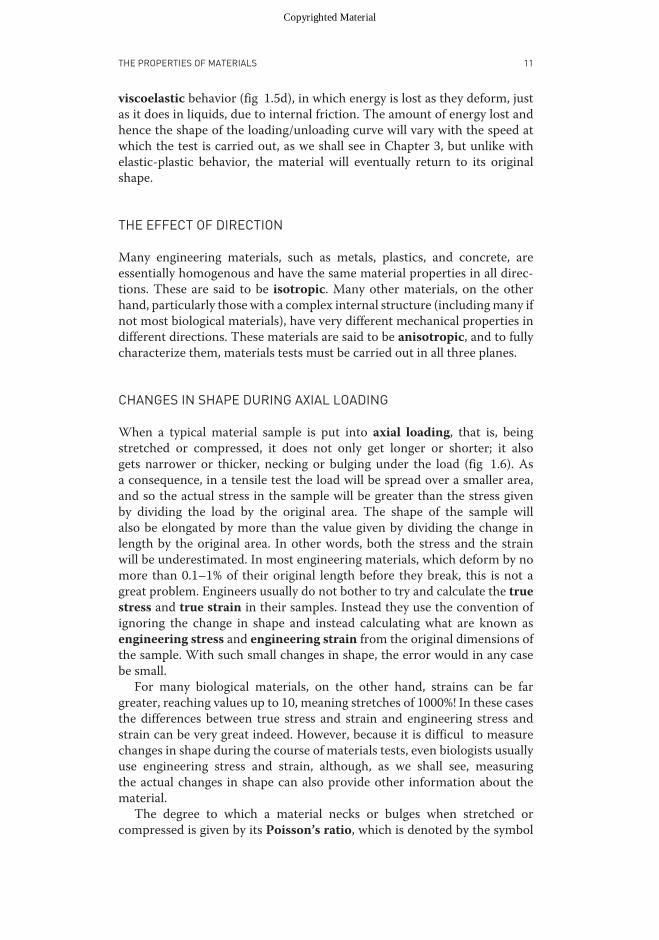
viscoelastic behavior (fig 1.5d), in which energy is lost as they deform, justas it does in liquids, due to internal friction. The amount of energy lost andhence the shape of the loading/unloading curve will vary with the speed atwhich the test is carried out, as we shall see in Chapter 3, but unlike withelastic-plastic behavior, the material will eventually return to its originalshape.
THE EFFECT OF DIRECTION
Many engineering materials, such as metals, plastics, and concrete, areessentially homogenous and have the same material properties in all direc-tions. These are said to be isotropic. Many other materials, on the otherhand, particularly those with a complex internal structure (includingmany ifnot most biological materials), have very different mechanical properties indifferent directions. These materials are said to be anisotropic, and to fullycharacterize them, materials tests must be carried out in all three planes.
CHANGES IN SHAPE DURING AXIAL LOADING
When a typical material sample is put into axial loading, that is, beingstretched or compressed, it does not only get longer or shorter; it alsogets narrower or thicker, necking or bulging under the load (fig 1.6). Asa consequence, in a tensile test the load will be spread over a smaller area,and so the actual stress in the sample will be greater than the stress givenby dividing the load by the original area. The shape of the sample willalso be elongated by more than the value given by dividing the change inlength by the original area. In other words, both the stress and the strainwill be underestimated. In most engineering materials, which deform by nomore than 0.1–1% of their original length before they break, this is not agreat problem. Engineers usually do not bother to try and calculate the truestress and true strain in their samples. Instead they use the convention ofignoring the change in shape and instead calculating what are known asengineering stress and engineering strain from the original dimensions ofthe sample. With such small changes in shape, the error would in any casebe small.
For many biological materials, on the other hand, strains can be fargreater, reaching values up to 10, meaning stretches of 1000%! In these casesthe differences between true stress and strain and engineering stress andstrain can be very great indeed. However, because it is difficul to measurechanges in shape during the course of materials tests, even biologists usuallyuse engineering stress and strain, although, as we shall see, measuringthe actual changes in shape can also provide other information about thematerial.
The degree to which a material necks or bulges when stretched orcompressed is given by its Poisson’s ratio, which is denoted by the symbol
Copyrighted Material

July 28, 2011 Time: 10:54am chapter01.tex
12 CHAPTER 1
(a)
(b)
(c)
tension
compression
Figure 1.6. Shape changes during loading. If a specimen (a) is stretched (b), it willalso tend to get narrower, whereas if it is compressed (c), it will tend to bulgeoutwards.
ν and calculated using the equation
ν = − lateral strainaxial strain
(1.10)
For engineering materials that are isotropic, ν is usually between 0.25 and0.33. The upper theoretical limit for ν is supposed to be 0.5, since at thisvalue the volume ofmaterial will be unchanged as it is stretched; if the lengthincreases by 1%, both the thickness and width will decrease by 0.5%, and thetotal volume will remain the same. If the lateral strain in both directionswere greater than half the longitudinal strain, it would result in the volumedecreasing when a material was stretched and increasing when compressed,which would seem to be physically improbable.
Many biological materials behave in rather odd ways, however; beinganisotropic they may have different Poisson’s ratios in different directions.As we shall see later in the book, some biological materials also have veryhigh Poisson’s ratios, whereas others, such as cork, have values near zero; itis even possible to design materials with negative Poisson’s ratios, materialsthat expand laterally when stretched.
SHEAR
We have seen how the axial stresses of tension and compression deformmaterials, but materials can also be deformed by a different kind of stress,shear stress. Shear stress acts parallel to a material’s surface (fig 1.7),
Copyrighted Material

July 28, 2011 Time: 10:54am chapter01.tex
THE PROPERTIES OF MATERIALS 13
(a) (b) F
F
F
F γ
Figure 1.7. Shear stress deforms a square piece of material (a) into a rhombus shape(b) with shear strain γ .
tending to deform a rectangle into a parallelogram, a deformation knownas shear strain.
Shear Stress
Just as for axial stresses, the shear stress, which is denoted by τ , is ameasurement of the intensity of the shear force and is therefore given bythe expression
τ = F /A, (1.11)
where F is the shearing force that has been applied, and A is the area parallelto that force over which the force is applied. The units of shear stress are thesame as those of axial stress: newtons per square meter (Nm−2), or pascals(Pa). Note that if a unit of material is put into shear (fig 1.7b), the right-hand element being pushed upward, an equal and opposite shear force mustact downward on the left-hand face for the element to be in equilibrium.However, if those were the only forces on the element, they would form acouple, spinning the material counterclockwise. Therefore two other shearstresses are set up, a stress on the top surface acting toward the right, andone on the lower surface acting toward the left.
Shear Strain
Just as axial stresses cause axial strains, so shear stresses set up shear strains,which are the change in the angles within the elements, denoted by γ
(fig 1.7). Shear strains are expressed in radians, which, being ratios of the
Copyrighted Material

July 28, 2011 Time: 10:54am chapter01.tex
14 CHAPTER 1
angular displacement relative to a portion of the full circumference, aredimensionless, just like axial strains.
Determining Material Properties in Shear
The shear properties of a material can be determined by carrying out directshear tests or torsion tests (see chapters 3 and 10), the results of whichcan be worked up just like the results of axial tests to give a graph of shearstress against shear strain. The most important shear property, the shearmodulus,G, is determined similarly to Young’s modulus, using the equation
G = dτ/dγ. (1.12)
The Relationship between Axial Forces and Shear
At firs glance it seems as if axial and shear forces are quite different,unconnected forces. However, if we look at what happens during axial andshear loading, it becomes apparent that they are inextricably linked. Intensile and compressive tests, a square element at 45◦ to the loading willbe sheared (fig 1.8a–c), whereas in a shear test, a square element at 45◦ tothe loading will be stretched in one direction and compressed in the other(fig 1.8d,e). The amount of shear produced by a tensile test depends on thePoisson’s ratio of the material: materials with a larger ν will contract morelaterally than those with a smaller ν, so the shear strain caused by a giventensile strain will be greater. For this reason materials with a high Poisson’sratio will have a relatively lower shear modulus, G, compared with theirYoung’s modulus, E . It can be readily shown by a geometrical argument(Gere, 2004) that E and G are related by the expression
G = E2(1 + ν)
(1.13)
so the shear modulus G is typically between 1/3 and 1/2 of the Young’smodulus of a material, depending on its Poisson’s ratio. Note that thisexpression is valid only for isotropic materials and so should not be usedfor biological materials, where it can prove highly misleading!
PERFORMING MATERIAL TESTS
Many of the mechanical properties of a material can therefore be readilydetermined by carrying out one of two sorts of mechanical tests in whichmaterials are put into axial loading: tensile tests and compressive tests. Bothof these are most conveniently carried out in universal testing machines onspecially prepared samples.
Copyrighted Material

July 28, 2011 Time: 10:54am chapter01.tex
THE PROPERTIES OF MATERIALS 15
(a)
(c)
(b)
(d) (e)
Figure 1.8. The relationship between axial and shear strains. If a square element at45◦ (a) is stretched (b) or compressed (c), it will be sheared into a rhombus. Similarlyif a square element at 45◦ (d) is sheared (e), it will be stretched and compressed intoa rectangle.
Tensile Tests
For a tensile test, the test piece typically has a “dumbbell” form (fig 1.3a)with a relatively long, thin central portion and broad shoulders at each end.The sample is gripped firml at its shoulders by two clamps: the lower oneis mounted in the base of the machine; the upper one is attached via aload cell to a movable crosshead. To carry out the test, the crosshead isdriven upward at a constant speed, while the force required to stretch thesample is measured by the load cell. This data is transferred to a computerthat produces a readout of force versus deflectio and, given the originaldimensions of the sample, has the ability to calculate its material properties.It is assumed (fairly accurately) that all the stretching has occurred in thenarrow central section of the sample. The widening at the ends ensuresthat the sample breaks in this central section and not at the clamps, wherestresses can be concentrated.
Tensile tests have three main pitfalls. The firs is that with relatively thicksamples of stiff materials, the rigidity of the sample may approach that ofthe testing machine. When a test is carried out in this situation, the machineitself will deform significantly meaning that the readout overestimates thedeflectio of the sample and stiffness is underestimated. There are three
Copyrighted Material
July 28, 2011 Time: 10:54am chapter01.tex
16 CHAPTER 1
solutions to this problem: you can use a longer, narrower sample to reduceits rigidity; you can attach an extensometer, which directly measures strain,to the sample; or you can attach an electronic strain gauge to the sample(Biewener, 1994). The second problem with tensile tests is the difficultin producing the complex shape of the sample. Biological materials canbe prepared by cutting around a machined template, but doing so canprove difficult particularly for samples cut from small pieces of tissue. Thethird problem is that many biological materials, particularly the soft, wet,and slippery ones, can prove extremely difficul to clamp. In such casesbiomechanists may resort to a range of techniques: using sandpaper toroughen the clamps; freezing the clamps to harden the material within thejaws; gluing the sample to the clamps using a cyanoacrylate glue that bindsto water; or simply wrapping the sample around purpose-built attachments.
Compressive Tests
Some of the problems of tensile tests can be overcome by carrying outcompressive tests, in which a relatively thicker rod of material is squashedbetween two plates. The sample is much easier to machine because no ex-panded ends are needed, but the sample and plates must both be machinedflat Because the sample is relatively thicker, it will also be more rigid than atensile sample, so it is much more likely that strain will have to be measuredwith an extensometer. Compressive tests usually give values of stiffness verysimilar to those of tensile tests, but as we shall see, materials often have verydifferent tensile and compressive strengths. Therefore to fully characterizea material both tests may be needed.
Torsion Tests
The shear properties of materials can be determined using the sorts oftorsion tests we will examine more thoroughly in chapter 10.
Mechanical Testing with Homemade Equipment
Not everyone has access to a materials testing machine or can afford tobuy one. It may also be impossible to transport samples to the laboratory(for instance, if you want to investigate the properties of wood in a tropicalrainforest). Finally, most commercially available testing machines are justnot sensitive enough to measure the material properties of structuressuch as lengths of spider silk, which are very thin and compliant. Forthese situations, it is often necessary to construct purpose-built apparatus,which can work perfectly well. Nowadays, electronic force and displacementtransducers are fairly inexpensive and data logging into laptop computers isfairly straightforward. However, in certain situations electronic equipment
Copyrighted Material
July 28, 2011 Time: 10:54am chapter01.tex
THE PROPERTIES OF MATERIALS 17
may not be practicable or affordable, and good results may instead beachieved by purely mechanical means, either by measuring force with aspring gauge or by hanging weights on the end of a sample. Whichever waythe forces are measured, though, it must be remembered that tests can bedivided into two main types. For larger samples, displacement-controlledtests, in which the length of the sample is progressively altered while theforce required to do this is measured, are recommended. Not only is onecontrolling the independent variable of the stress-strain curve, but thesetests are also fairly safe, since when the material breaks the only energyreleased is that which is stored in the sample. In contrast, load-controlledtests, such as those in which weights are hung on the end of a sample,are very easy to perform, but failure of the sample can result in potentiallydamaging deflectio of the clamps and of the mechanism that is applyingthe load.
FAILURE AND BREAKING
As we have seen, it is relatively easy to explain how and why materials resistbeing deformed; one just has to consider the forces set up between theiratoms. The fracture behavior of materials is more difficul to understand. Itmight be expected that the strength of a piece of material will be directlyproportional both to the strength of its interatomic bonds and to its cross-sectional area. Hence its breaking stress should be high and independent ofthe sample size. However, most materials havemuch lower breaking stressesthan would be predicted from the strength of their chemical bonds, andlarger pieces of material often have far lower breaking stresses than smallones. Brittle materials also tend to be much easier to break than tough ones,even if they have the same breaking stress.
Throughout the last century, with the pioneering work of C. E. Inglis andA. A. Griffit (recounted very clearly by Gordon [1968]), it has been shownthat to explain fracture, it is necessary to consider not only the overall stressin materials but also the distribution of stress within the sample and thechanges in energy involved.
STRESS CONCENTRATIONS AND NOTCH SENSITIVITY
Let us f rst examine the distribution of stress within a material that is beingstretched in a tensile test. If the test piece used is perfectly smooth andfree of internal f aws, the stresses will be evenly distributed throughout thematerial and the strength of the sample will equal the breaking stress of thematerial times its cross-sectional area. However, if there is a small scratchor ridge in the surface, or a f aw within the material, the stresses will haveto divert around these obstructions, and stress concentrations will be setup at their sides (fig 1.9a). The stress concentration factor will depend onthe shape of these imperfections. For a circular hole or semicircular notch,
Copyrighted Material
July 28, 2011 Time: 10:54am chapter01.tex
18 CHAPTER 1
(b)
Stre
ngth
tough
(a)
brittle
Relative notch length
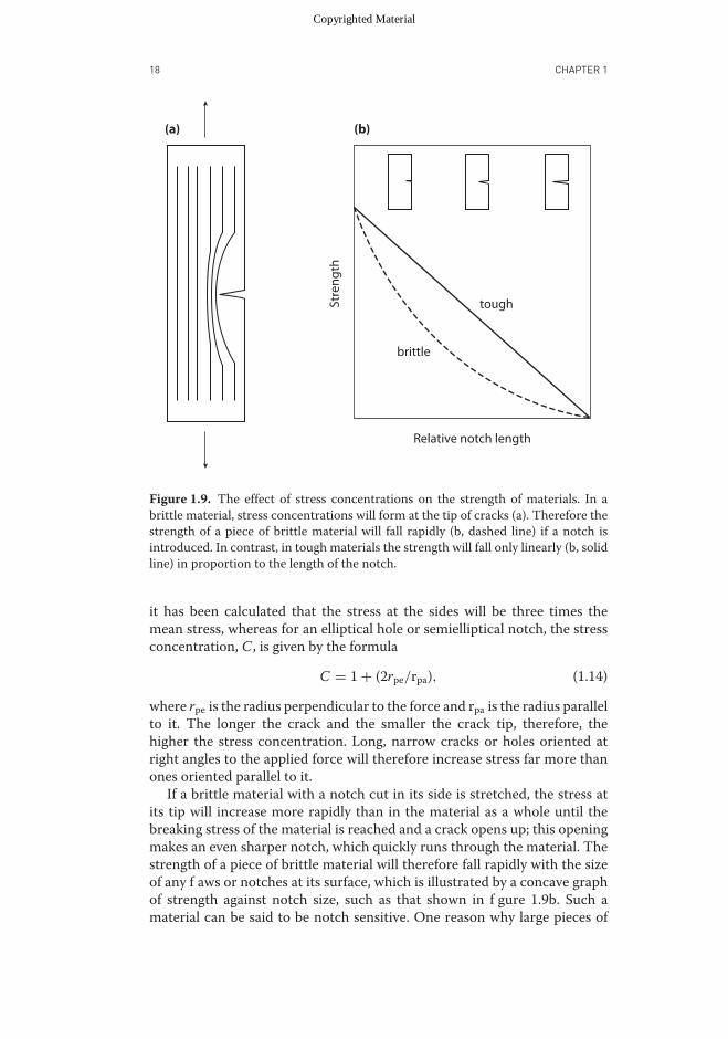
Figure 1.9. The effect of stress concentrations on the strength of materials. In abrittle material, stress concentrations will form at the tip of cracks (a). Therefore thestrength of a piece of brittle material will fall rapidly (b, dashed line) if a notch isintroduced. In contrast, in tough materials the strength will fall only linearly (b, solidline) in proportion to the length of the notch.
it has been calculated that the stress at the sides will be three times themean stress, whereas for an elliptical hole or semielliptical notch, the stressconcentration, C , is given by the formula
C = 1 + (2rpe/rpa), (1.14)
where rpe is the radius perpendicular to the force and rpa is the radius parallelto it. The longer the crack and the smaller the crack tip, therefore, thehigher the stress concentration. Long, narrow cracks or holes oriented atright angles to the applied force will therefore increase stress far more thanones oriented parallel to it.
If a brittle material with a notch cut in its side is stretched, the stress atits tip will increase more rapidly than in the material as a whole until thebreaking stress of the material is reached and a crack opens up; this openingmakes an even sharper notch, which quickly runs through the material. Thestrength of a piece of brittle material will therefore fall rapidly with the sizeof any f aws or notches at its surface, which is illustrated by a concave graphof strength against notch size, such as that shown in f gure 1.9b. Such amaterial can be said to be notch sensitive. One reason why large pieces of
Copyrighted Material

July 28, 2011 Time: 10:54am chapter01.tex
THE PROPERTIES OF MATERIALS 19
glass have a lower breaking stress than small ones is that they are more likelyto have larger, sharper notches.
In contrast, if a tough material with a notch cut into it is stretched,the material will yield rather than break at the tip of the notch, deformingmarkedly and so blunting the crack tip. As a consequence the strength ofa piece of tough material will fall slowly and linearly with notch length(fig 1.9b) so that the strength is proportional to the area of intact tissueat the end of the notch. Materials showing this sort of behavior are said tobe notch insensitive. Tough materials therefore show low notch sensitivity,and brittle materials show high notch sensitivity.
ENERGY CHANGES AND THE WORK OF FRACTURE
The argument above based on stress concentrations works well qualitatively,but it is less successful in quantitatively predicting and understanding thebehavior of tough materials. Another, even more useful, way of thinkingabout what happens during failure is to look at the energy changes involved.
When an object breaks, interatomic bonds are broken, creating two newsurfaces; this process requires energy, and at firs glance it appears difficulto understand where that energy might come from. Let us examine thesituation shown in figur 1.10, in which a plate of material of thickness tand with a crack in it of length a is being stretched, producing an overalltensile stress in the plate, σ . Elastic energy is stored in the plate, but becausethe stresses are being diverted around the tip of the crack, small areas aboveand below the crack will be unstressed and will store no energy. Here it isassumed that these areas have the shape of a right triangle, but this is just arough approximation. If the crack extends by a distance da, a greater volumeof material will become unstressed. The amount of elastic energy, We, thatthis will release is equal to the energy stored per unit volume of material(which we have seen from equation 1.8 is σ 2/2E ) times the extra volume,which from geometry can readily seen to be 2t a da.
Extending the crack increases its surface area by the amount 2t da, sincethe crack has both an upper and lower surface, and if the surface energy(in Jm−2, the energy required to produce a unit area of new surface) of thematerial is g , the surface energy required to extend the crack, Ws, is 2tg da.For the crack to spontaneously extend, the energy released by unstressingthematerial around the crackmust at least equal the surface energy requiredto extend it, so that
We ≥ Ws
so
σ 2/2E × 2ta da ≥ 2tgda.
Therefore
σ 2 ≥ 2Eg/a.
Copyrighted Material

July 28, 2011 Time: 10:54am chapter01.tex
20 CHAPTER 1
da
a
Figure 1.10. The effect of increasing crack length on the volume of unstressedmaterial. If the crack extends a distance da, the material between the dashed andsolid lines becomes unstressed, releasing energy.
More sophisticated and precise analysis gives a slightly different figurfor σ of
σ ≥ (2Eg/πa)0.5 (1.15)
At low stresses a crack cannot extend because not enough energy is releasedfrom the relaxation around the crack tip to open the crack. Once σ exceedsthe critical value, however, the crack can and will extend, and as it lengthensit becomes more and more energetically favorable for it to do so. The crackwill run very rapidly across the material and break it. Note that the longerthe crack is initially, the lower the stress required to break the material. Thecritical crack length acrit can readily be obtained by rearranging 1.15 to give
acrit = 2Eg/πσ 2. (1.16)
It is greater for stiffer materials and ones with higher surface energy anddecreases rapidly with the stress applied.
In fact, the surface energy of most materials, the energy that is required tobreak the top layer of interatomic bonds, is very low, approximately 1 Jm−2,so for a brittle material even tiny scratches can make it much weaker.
Copyrighted Material

July 28, 2011 Time: 10:54am chapter01.tex
THE PROPERTIES OF MATERIALS 21
In toughmaterials, the amount of energy needed tomake new surfaces, orthework of fracture, is far higher, because yieldingmay involve a wide rangeof mechanisms that absorb energy; it may involve deforming the materialnear the crack tip plastically, as in metals, or creating a rough fracturesurface with a much greater surface area, as in fiberglas and green wood.Many different fracture tests may be used to calculate the work of fracture,Wf, which is define as the energy to produce the crack, e, divided by thecrack’s area, A (not the total new area produced, which would be twice thearea of the crack) giving the expression
Wf = e/A. (1.17)
Work of fracture, like surface energy, therefore has the units Jm−2. Thecritical crack length for a tough material is derived by substituting work offracture into equation 1.16 to give the expression
acrit = EWf/πσ 2. (1.18)
As we shall see, many biological materials have particularly sophisticatedtoughening mechanisms.
MEASURING WORK OF FRACTURE
You might think it should be very easy to measure the work of fracture of abiological material. All you would need to do would be to perform a simpletensile test, and the work of fracture could be estimated from the area underthe stress-strain curve up to the point of failure. Unfortunately things arenot that simple. When a tensile piece is broken, some of the energy that wasstored elastically may not be used to break the material but may instead bereleased explosively, making a snapping noise and flingin material about.The area under the stress-strain curve will therefore overestimate the workof fracture, and the error will be most severe when using long test specimensthat store more energy. The problem could be minimized by using a veryshort test specimen, but machine compliance would then become a majordifficulty Instead, materials scientists have developed a range of tests tomeasure the work of fracture, although each of these has its own limitations.
Controlled Cracking
One method of overcoming the loss of stored elastic energy is to carry outa more controlled test in which the crack grows in a stable fashion. Oneway of doing this is to sequentially load and unload a test piece that isclamped asymmetrically in the testing machine. Examples of such methodsinclude the compact tension test (Vincent, 1992) and the double cantileverbeam (fig 1.11a). The specimen may be sequentially loaded and unloadedseveral times, driving the crack across the specimen, between which actionsit should return to its original shape. The work of fracture can be calculated
Copyrighted Material
July 28, 2011 Time: 10:54am chapter01.tex
22 CHAPTER 1
(a) (b)
(d) (e)
(c)
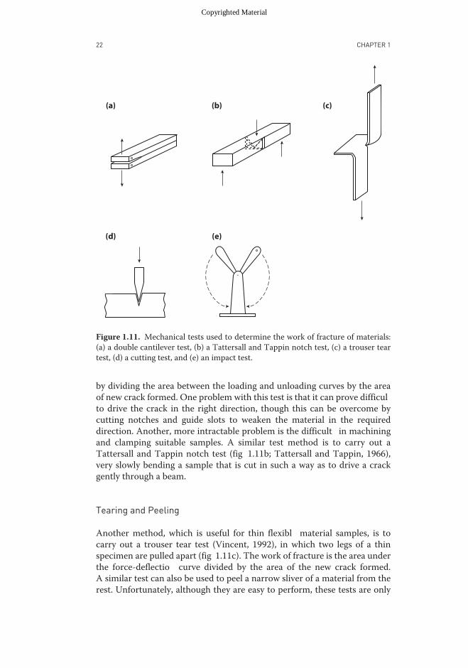
Figure 1.11. Mechanical tests used to determine the work of fracture of materials:(a) a double cantilever test, (b) a Tattersall and Tappin notch test, (c) a trouser teartest, (d) a cutting test, and (e) an impact test.
by dividing the area between the loading and unloading curves by the areaof new crack formed. One problem with this test is that it can prove difficulto drive the crack in the right direction, though this can be overcome bycutting notches and guide slots to weaken the material in the requireddirection. Another, more intractable problem is the difficult in machiningand clamping suitable samples. A similar test method is to carry out aTattersall and Tappin notch test (fig 1.11b; Tattersall and Tappin, 1966),very slowly bending a sample that is cut in such a way as to drive a crackgently through a beam.
Tearing and Peeling
Another method, which is useful for thin flexibl material samples, is tocarry out a trouser tear test (Vincent, 1992), in which two legs of a thinspecimen are pulled apart (fig 1.11c). The work of fracture is the area underthe force-deflectio curve divided by the area of the new crack formed.A similar test can also be used to peel a narrow sliver of a material from therest. Unfortunately, although they are easy to perform, these tests are only
Copyrighted Material
July 28, 2011 Time: 10:54am chapter01.tex
THE PROPERTIES OF MATERIALS 23
really useful for materials that have preferred lines of failure, such as planttissues, in which longitudinal fiber constrain the cracks to run betweenthem; otherwise the tears are all too readily diverted in the wrong direction.
Cutting Tests
To overcome the problem of cracks moving in the wrong direction, severaldifferent kinds of cutting test have recently been devised. Materials maybe cut through with a sharp blade (fig 1.11d), whether it be that of aninstrumented microtome (Atkins and Vincent, 1984), a guillotine (Atkinsand Mai, 1979), an inclined razor blade (Ang et al., 2008), or nail clippers(Bonser et al., 2004). Alternatively, one can use the double blades ofa sharp pair of scissors (Darvell et al., 1996). In all of these cases thefracture is constrained to run in the desired direction. All of these tests arestraightforward to perform, and the work of fracture is found by dividingthe energy needed to cut through the specimen by the area of the fracturesurface produced, although in scissor and guillotine tests, the friction ofthe devices also must be taken into account. The tests can also detectparticularly tough regions of the material, such as fiber or veins, since theforce needed to cut through them is greater and allows their toughness to becalculated separately. However, because the cuts constrain the direction ofthe crack very precisely, these tests measure the minimum work of fractureof the material and cannot detect how much toughening is given to thematerial by the sorts of mechanisms that involve diverting the crack.
Impact Tests
A f nal series of tests to measure work of fracture involves specimens beingstruck by the impact of a moving pendulum and measuring the energyrequired to snap them (Vincent, 1992). Typically a notched bar or rod ofmaterial is mounted in one arm of the apparatus and is hit by the otherswinging pendulum (fig 1.11e). The specimen is broken transversely, theenergy required being supplied by the kinetic energy of the pendulum, whichconsequently does not rise to so great a height after the impact as before.The work of fracture is the change in potential energy of the pendulumbefore and after the test divided by the cross-sectional area of the bar. Thistest works well for many stiffer materials, but since the precise conditionsof loading are usually unknown, it is often hard to relate the results fromthis test to those of the other tests. In particular, the impacts tend to be veryrapid, so less energy is used to break viscoelastic materials than in the otherslower methods, and the work of fracture is consequently underestimated.
Other Measurements of Work of Fracture
The work of fracture of amaterial is usually regarded as being the same thingas its toughness. However, other, quite different definition of toughness
Copyrighted Material

July 28, 2011 Time: 10:54am chapter01.tex
24 CHAPTER 1
Table 1.1Properties of Some Man-Made and Biological Materials.. . . . . . . . . . . . . . . . . . . . . . . . . . . . . . . . . . . . . . . . . . . . . . . . . . . . . .Material Stiffness Tensile Extensibility Strain Resilience Work of
(MPa) Strength energy (%) fracture(MPa) (MJm−3) (Jm−2)
Steel 200,000 400 0.008 1 100,000–1,000,000
Glass 70,000 170 0.002 0.2 1–10Concrete 100,000 5 0.00005 0.0001 3–40Rubber 3 7 3 10 90Resilin 2 4 2 4 93Abductin 4 75–90Elastin 1.2 2 1 0.8 75Mucus 0.0002 0.0005 5 55Mesoglea 0.001 1,200Moth Silk 4000 2000 0.3 200 35Tendon 2000 100 0.1 3 93Keratin 3000 300 0.2 15,000Cuticle 5000 60 0.01 0.3 2,000Unlignifie 3,000 100 0.05 3,000plantcell wallWood 4,000 40 0.01 0.5 30,000Bone 17,000 200 0.006 0.6 2,000Dentine 15,000 50 0.003 0.1 500Enamel 50,000 35 0.0005 0.02 200Shell (nacre) 30,000 50 0.006 0.15 1600
are sometimes presented in papers. Some authors (see, for instance, Goslineet al., 2002) present values for toughness with the units Jm−3. These valueswere actually derived from the area under the stress-strain graphs and soare more correctly measurements of the energy-storage capabilities of thematerials. It is better, therefore, to use the term work of fracture.
COMPARING THE PROPERTIES OF MATERIALS
All the complexity of the properties of materials and of materials testingmeans that it is surprisingly complicated to compare the properties ofdifferent materials. They can differ in their stiffness, their strength, theirability to store and release energy, and in their toughness. Some materialsare also better at resisting tension, whereas others resist compression better;and some materials have the same properties in all directions, whereaswith others, their performance depends on the direction in which they arestressed.
A good way to get an instinctive idea of how to compare materials is tothink of some everyday objects familiar even to children. Jell-O has very
Copyrighted Material

July 28, 2011 Time: 10:54am chapter01.tex
THE PROPERTIES OF MATERIALS 25
low stiffness and strength and is also very brittle, making it easy for evenvery young children to cut up and eat. Cookies, in contrast, are stiff butnot very strong, so a child can carry one around without breaking it yetstill readily bite into it. Toffees are both stiff and strong, although they canbe smashed to smithereens when hit by a hammer, showing that they arebrittle. To eat them a child has to put them whole into their mouth, beforesoftening them and dissolving them with their warm saliva. Pencils are stiff,strong, and extremely tough, so they can take a lot of punishment withoutbreaking, although the brittle leads are easy to snap off. Rubber bands havelow stiffness, but they are very stretchy, so they are reasonably strong andcan store a lot of energy, which makes them ideal for use as slingshots.
What about “grown-up” materials? Well, steel is one of the most popularmaterials in engineering because it is stiff, strong, and tough and so is idealfor taking loads and resisting impacts. This is why it is used to make theshells of cars. Glass is far less useful, because although it is almost as stiff andstrong as steel, it is extremely brittle and so shatters on impact. Concrete iswidely used to build walls and f oors because it is stiff and extremely strongin compression, but because it cannot take tension, it cannot be used tomake the roofs of buildings without being reinforced with steel.
The properties of some important man-made materials and those of thenatural materials we will encounter in the next few chapters are shown forease of comparison in table 1.1. Perhaps the material that acts as the bestsingle benchmark is rubber, since we can deform it fairly easily by handand so get an intuitive feel for its properties. Most of its properties also,have small integer values for stiffness and strength (in MPa), strain energy(in MJm−3), and maximum strain. Some materials, such as mucus andmesoglea, are more compliant than rubber, but most “rigid materials” arethousands of times stiffer and tens of times stronger but many times lessextensible.
As we shall see in the next few chapters, it is practically impossible toproduce materials in which all the properties are maximized; in general,the stiffer and stronger a material is, the less it can be stretched. Thereis therefore no one “super” material that is ideal for all purposes, andthe mechanical design of organisms consists of making materials that aresuitable for a particular role and arranging them in the right way within thebody. That topic is what most of the rest of this book is about.
Copyrighted Material