THE PROPANE TECHNICAL POCKET GUIDE - Build With · PDF fileThe Propane Technical Pocket Guide...
28
DATA AND GUIDANCE FOR CONSTRUCTION PROJECTS TECHNICAL THE PROPANE POCKET GUIDE FOR RESIDENTIAL AND COMMERCIAL CONSTRUCTION
Transcript of THE PROPANE TECHNICAL POCKET GUIDE - Build With · PDF fileThe Propane Technical Pocket Guide...
DATA AND GUIDANCE FOR CONSTRUCTION PROJECTS
TECHNICALTHE PROPANE
POCKET GUIDEFOR RESIDENTIAL AND COMMERCIAL CONSTRUCTION
1
The Propane Technical Pocket Guide
The Propane Technical Pocket Guide provides general information on how to prepare for the installation of propane systems for residential and commercial consumers. It includes key data and answers important questions relevant to construction professionals planning to incorporate propane in their construction projects.
This guide is not intended to conflict with federal, state, or local ordinances or pertinent industry regulations, including National Fire Protection Association (NFPA) 54 and 58. These should be observed at all times.
The Propane Technical Pocket Guide must not be considered a replacement for proper training on the installation and start-up of propane systems. Propane system installations should always be performed by trained propane professionals. For more information go to your local propane professional or propanecouncil.org/ safety-and-training.
1
Table of Contents
2 Propane Resources
3 Properties of Propane and Natural Gas (Methane)
6 Vapor Pressure of Gas
7 Determining Total Load
9 Vaporization Rates
11 Propane Jurisdictional Systems
12 Container Location and Installation
16 Pipe and Tubing Sizing
18 Gas Piping Inlet Positioning
19 Gas Piping Hangers, Supports, and Anchors
20 The Propane-Ready Home
21 Propane Generator Installation
22 Basic Electricity for Propane Appliance Service
24 Conversion Factors

2 3
Propane Resources
Buildwithpropane.com Construction pros should visit buildwithpropane.com to check out the latest news and insights on building products and trends, learn how to install and operate propane equipment, and find information on construction-related events, conferences, and conventions. Propane Training Academy The Propane Education & Research Council (PERC) provides free continuing education courses on propane and its many residential and commercial applications, installation specifics, and products, approved by the American Institute of Architects (AIA), National Association of Home Builders (NAHB), U.S. Green Building Council (USGBC), and National Association of the Remodeling Industry (NARI). Fulfill your CEU requirements today at buildwithpropane .com/training. Propane Safety — propanecouncil.org/safety-and-training/ Training and informing industry professionals and consumers on the safe handling, storage, and use of propane is a top priority at PERC. PERC’s safety website provides training, resources, and compliance materials. Find a Propane Retailer — retailers.propane.com A trained professional can answer your questions about propane applications. Use this handy online tool to find a propane retailer in your area, and you’ll be on your way to a successful, professional propane project. National Fire Protection Association (NFPA) — nfpa.org NFPA standards govern the use of propane and gas in buildings. Visit nfpa.org for the latest information.

3
Table 1A. Approximate Properties of Gases (U.S.)
PROPERTYPropane Natural Gas
C3H8 CH4
Initial Boiling Point -44 -259
Specific Gravity of Liquid (Water at 1.0) at 60°F
0.504 n/a
Weight per Gallon of Liquid at 60°F, LB
4.2 n/a
Specific Heat of Liquid, Btu/LB at 60°F
0.63 n/a
Cubic Feet of Vapor per Gallon at 60°F
36.38 n/a
Cubic Feet of Vapor per Pound at 60°F
8.66 23.55
Specific Gravity of Vapor (Air = 1.0) at 60°F
1.5 0.6
Ignition Temperature in Air, °F 920–1,120 1,301
Maximum Flame Temperature in Air, °F
3,595 2,834
Cubic Feet of Air Required to Burn One Cubic Foot of Gas
23.68 9.57
Limits of Flammability in Air, % of Vapor in Air-Gas Mix: (a) Lower (b) Upper
2.159.6
515
Latent Heat of Vaporization at Boiling Point: (a) Btu per Pound (b) Btu per Gallon
184773
219n/a
Total Heating Values After Vaporization: (a) Btu per Cubic Foot (b) Btu per Pound (c) Btu per Gallon
2,48821,54891,502
1,01228,875
n/a
Properties of Propane and Natural Gas (Methane)
4 5
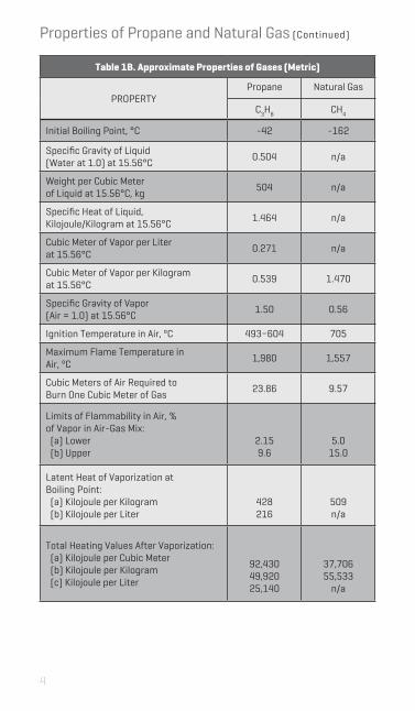
Table 1B. Approximate Properties of Gases (Metric)
PROPERTYPropane Natural Gas
C3H8 CH4
Initial Boiling Point, °C -42 -162
Specific Gravity of Liquid (Water at 1.0) at 15.56°C
0.504 n/a
Weight per Cubic Meter of Liquid at 15.56°C, kg
504 n/a
Specific Heat of Liquid, Kilojoule/Kilogram at 15.56°C
1.464 n/a
Cubic Meter of Vapor per Liter at 15.56°C
0.271 n/a
Cubic Meter of Vapor per Kilogram at 15.56°C
0.539 1.470
Specific Gravity of Vapor (Air = 1.0) at 15.56°C
1.50 0.56
Ignition Temperature in Air, ºC 493–604 705
Maximum Flame Temperature in Air, ºC
1,980 1,557
Cubic Meters of Air Required to Burn One Cubic Meter of Gas
23.86 9.57
Limits of Flammability in Air, % of Vapor in Air-Gas Mix: (a) Lower (b) Upper
2.159.6
5.015.0
Latent Heat of Vaporization at Boiling Point: (a) Kilojoule per Kilogram (b) Kilojoule per Liter
428216
509n/a
Total Heating Values After Vaporization: (a) Kilojoule per Cubic Meter (b) Kilojoule per Kilogram (c) Kilojoule per Liter
92,43049,92025,140
37,70655,533
n/a
Properties of Propane and Natural Gas (Continued)

5
Table 1C. Energy Content and Environmental Impact of Various Energy Sources
Propane (per ft3)
Methane Propane (per gallon)
Fuel Oil Electricity
Energy Value2,524 Btu/ft3
1,012 Btu/ft3
91,500 Btu/gal
139,400 Btu/gal
3,413 Btu/kWh
CO2 Emissions (lbs/MMBtu)
139.2 115.3 139.2 161.4 389.5
Source Energy Multiplier*
1.151 1.092 1.151 1.158 3.365
*Source Energy Multiplier is the total units of energy that go into generation, processing, and delivery for a particular energy source to produce one unit of energy at the site. The high source energy multiplier for electricity is due in
part to transmission and distribution losses that do not occur with propane.

6 7
Table 2. Vapor Pressures
TEMPERATUREApproximate Vapor Pressure, PSIG (bar)
Propane to Butane
ºF ºC 100% 80/20 60/40 50/50 40/60 20/80 100%
-40 -40 3.6 (0.25) - - - - - -
-30 -34.4 8 (0.55)
4.5 (0.31) - - - - -
-20 -28.9 13.5 (0.93)
9.2 (0.63)
4.9 (0.34)
1.9 (0.13) - - -
-10 -23.3 20 (1.4)
16 (1.1)
9 (0.62)
6 (0.41)
3.5 (0.24) - -
0 -17.8 28 (1.9)
22 (1.5)
15 (1.0)
11 (0.76)
7.3 (0.50) - -
10 -12.2 37 (2.6)
29 (2.0)
20 (1.4)
17 (1.2)
13 (0.90)
3.4 (0.23) -
20 -6.7 47 (3.2)
36(2.5)
28 (1.9)
23 (1.6)
18 (1.2)
7.4 (0.51) -
30 -1.1 58 (4.0)
45 (3.1)
35 (2.4)
29 (2.0)
24 (1.7)
13 (0.9) -
40 4.4 72 (5.0)
58 (4.0)
44 (3.0)
37 (2.6)
32 (2.2)
18 (1.2)
3 (0.21)
50 10 86 (5.9)
69 (4.8)
53 (3.7)
46 (3.2)
40 (2.8)
24 (1.7)
6.9 (0.58)
60 15.6 102 (7.0)
80 (5.5)
65 (4.5)
56 (3.9)
49 (3.4)
30 (2.1)
12 (0.83)
70 21.1 127 (8.8)
95 (6.6)
78 (5.4)
68 (4.7)
59 (4.1)
38 (2.6)
17 (1.2)
80 26.7 140 (9.7)
125 (8.6)
90 (6.2)
80 (5.5)
70 (4.8)
46 (3.2)
23 (1.6)
90 32.2 165 (11.4)
140 (9.7)
112 (7.7)
95 (6.6)
82 (5.7)
56 (3.9)
29 (2.0)
100 37.8 196 (13.5)
168 (11.6)
137 (9.4)
123 (8.5)
100 (6.9)
69 (4.8)
36 (2.5)
110 43.3 220 (15.2)
185 (12.8)
165 (11.4)
148 (10.2)
130 (9.0)
80 (5.5)
45 (3.1)
Table adapted from LP-Gas Serviceman’s Handbook 2012
Vapor Pressure of GasVapor pressure can be defined as the force exerted by a gas or liquid attempting to escape from a container. It is what forces propane gas from the container through the piping and regulator system to the appliance.
Outside temperature affects the propane vapor pressure in the container. A lower temperature creates lower propane vapor pressure in the container. If container pressure is too low, not enough gas will reach the appliance. Placement of the container below grade can help alleviate wide swings in vapor pressures during the year due to the consistent temperature of the earth.
The table below shows vapor pressures for propane and butane at various outside temperatures.

7
Table 3A. Approximate Gas Input for Typical Appliances
APPLIANCEApproximate
Input Btu/HourWarm Air Furnace Single Family Multifamily, per Unit
100,00060,000
Hydronic Boiler, Space Heating Single Family Multifamily, per Unit
100,00060,000
Hydronic Boiler, Space and Water Heating Single Family Multifamily, per Unit
120,00075,000
Water Heater, Storage, 30- to 40-Gallon TankWater Heater, Storage, 50-Gallon TankWater Heater, Tankless 2 GPM 4 GPM 6 GPMWater Heater, Domestic, Circulating, or Side-Arm
35,00050,000
142,800285,000428,40035,000
Range, Freestanding, DomesticBuilt-In Oven or Broiler Unit, DomesticBuilt-In Top Unit, Domestic
65,00025,00040,000
RefrigeratorClothes Dryer, Type 1 (Domestic)Gas Fireplace, Direct VentGas LogBarbecueGas Light
3,00035,00040,00080,00040,0002,500
Reprinted with permission from NFPA 54-2018, National Fuel Gas Code, Copyright© 2017, National Fire Protection Association. This reprinted material is not the complete and official position of the NFPA on the referenced subject, which is represented only by the standard in its entirety and can be obtained through the NFPA web site www.nfpa.org.
Determining Total LoadThe best way to determine British thermal unit (Btu) input is from the appliance nameplate or from the manufacturer’s catalog. Add the input of all the appliances for the total load. If specific appliance capacity information is not available, refer to Table 3A below. Remember to allow for appliances that may be installed at a later date, especially if a manifold with unused ports is installed. Some examples may include gas outlets for fireplaces and grills and a switch from an electric to a gas dryer.
If the propane load needs to be in standard cubic feet per hour (SCFH), divide the Btu/hour load by 2,488 to get SCFH. Conversely, the Btu/hour capacity can be obtained from SCFH by multiplying the SCFH figure by 2,488.
Your propane provider will need to know the total Btu load of the system to be served to properly design the propane system, including determining the proper sizing and distance placement of the propane tank, the location of regulators, and the specifications of the underground high-pressure piping system.

8 9
Determining Total Load (Continued)
A variety of mechanical systems are available for space heating and water heating in homes. These systems have varying energy sources and varying efficiency levels. Table 3B below provides simple calculations that allow contractors and homeowners to estimate the dollars per million Btu depending on the equipment type, efficiency, and energy price. The “$/MMBtu” figure can be compared across different options to evaluate them.
Table 3B. Operating Costs and Equipment Efficiencies of Residential Space and Water Heating Systems
SPACE HEATINGPricing Estimation
Formula ($/MMBtu)
Typical Equipment Efficiency Ranges for
Newer Systems
Propane (furnace or boiler)
(10.9 x $/gal) (AFUE/100)
AFUE: 78–98
Natural Gas (furnace or boiler)
(10 x $/therm) (AFUE/100)
AFUE: 78–98
Fuel Oil (furnace or boiler)
(7.2 x $/gal)(AFUE/100)
AFUE: 78–95
Electric Resistance 293 x $/kWh COP: 1.0
Electric Air Source Heat Pump
(1,000 x $/kWh)HSPF
HSPF: 8.2–10.0
Electric Ground Source Heat Pump
(293 x $/kWh) COP
COP: 3.0–4.7*
WATER HEATINGPricing Estimation
Formula ($/MMBtu)
Typical Storage Water Heater
Energy Factors (EF)
Typical Instantaneous Water HeaterEnergy Factor
(EF)
Propane (10.9 x $/gal)/EF 0.62–0.70 0.82–0.98
Natural Gas (10 x $/therm)/EF 0.62–0.70 0.82–0.98
Fuel Oil (7.2 x $/gal)/EF 0.62–0.68 —
Electric Resistance (293 x $/kWh)/EF 0.95 0.93–1.0
Heat PumpWater Heater
(293 x $/kWh)/EF2.0–2.50 —
*Note that COP does not account for pump energy used to move refrigerant through the extensive ground loop.
9
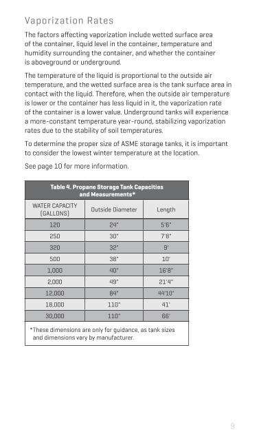
Vaporization RatesThe factors affecting vaporization include wetted surface area of the container, liquid level in the container, temperature and humidity surrounding the container, and whether the container is aboveground or underground.
The temperature of the liquid is proportional to the outside air temperature, and the wetted surface area is the tank surface area in contact with the liquid. Therefore, when the outside air temperature is lower or the container has less liquid in it, the vaporization rate of the container is a lower value. Underground tanks will experience a more-constant temperature year-round, stabilizing vaporization rates due to the stability of soil temperatures.
To determine the proper size of ASME storage tanks, it is important to consider the lowest winter temperature at the location.
See page 10 for more information.
Table 4. Propane Storage Tank Capacities and Measurements*
WATER CAPACITY (GALLONS) Outside Diameter Length
120 24" 5'6"
250 30" 7'8"
320 32" 9'
500 38" 10'
1,000 40" 16'8"
2,000 49" 21'4"
12,000 84" 44'10"
18,000 110" 41'
30,000 110" 66'
Electric Air Source Heat Pump
(293 x $/kWh)/EF2.0–2.51
.* These dimensions are only for guidance, as tank sizes
and dimensions vary by manufacturer.
10 11
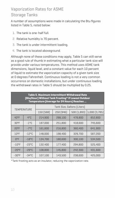
Table 5. Maximum Intermittent Withdrawal Rate (Btu/Hour) Without Tank Frosting* If Lowest Outdoor
Temperature (Average for 24 Hours) Reaches ...
TEMPERATURETank Size, Gallons (Liters)
150 (568) 250 (946) 500 (1,893) 1,000 (3,785)
40ºF 4°C 214,900 288,100 478,800 852,800
30ºF -1°C 187,000 251,800 418,600 745,600
20ºF -7°C 161,800 216,800 360,400 641,900
10ºF -12°C 148,000 198,400 329,700 587,200
0ºF -18°C 134,700 180,600 300,100 534,500
-10ºF -23°C 132,400 177,400 294,800 525,400
-20ºF -29°C 108,800 145,800 242,300 431,600
-30ºF -34°C 107,100 143,500 238,600 425,000
*Tank frosting acts as an insulator, reducing the vaporization rate.
Vaporization Rates for ASME Storage TanksA number of assumptions were made in calculating the Btu figures listed in Table 5, noted below:
1. The tank is one-half full.
2. Relative humidity is 70 percent.
3. The tank is under intermittent loading.
4. The tank is located aboveground.
Although none of these conditions may apply, Table 5 can still serve as a good rule of thumb in estimating what a particular tank size will provide under various temperatures. This method uses ASME tank dimensions, liquid level, and a constant value for each 10 percent of liquid to estimate the vaporization capacity of a given tank size at 0 degrees Fahrenheit. Continuous loading is not a very common occurrence on domestic installations, but under continuous loading the withdrawal rates in Table 5 should be multiplied by 0.25.
11
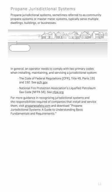
Propane Jurisdictional SystemsPropane jurisdictional systems, sometimes referred to as community propane systems or master meter systems, typically serve multiple dwellings, buildings, or businesses.
In general, an operator needs to comply with two primary codes when installing, maintaining, and servicing a jurisdictional system:
• The Code of Federal Regulations (CFR), Title 49, Parts 191 and 192. See ecfr.gov.
• National Fire Protection Association’s Liquefied Petroleum Gas Code (NFPA 58). See nfpa.org.
For more guidance in recognizing jurisdictional systems and the responsibilities required of companies that install and service them, visit propanesafety.com and download “Propane Jurisdictional Systems: A Guide to Understanding Basic Fundamentals and Requirements.”

12 13
Container Location and InstallationOnce the proper size of the ASME storage tank has been determined, careful attention must be given to the most convenient yet safe place for its location on the customer’s property.
The container should be placed in a location that pleases the customer but does not conflict with state and local regulations or NFPA 58, Storage and Handling of Liquefied Petroleum Gases. Refer to this standard and consult with your propane professional to determine the appropriate placement of propane containers.
In general, storage tanks should be placed in an accessible location for filling. Aboveground tanks should be supported by a concrete pad or concrete blocks of appropriate size and reinforcement. For underground propane tanks, properly determining the depth and size of the burial location is critical for placement of the tank. To avoid damage, underground propane tanks should be installed in a location where the delivery truck will not need to drive over septic tanks or other underground amenities. All propane storage tanks should be located away from vehicular traffic.
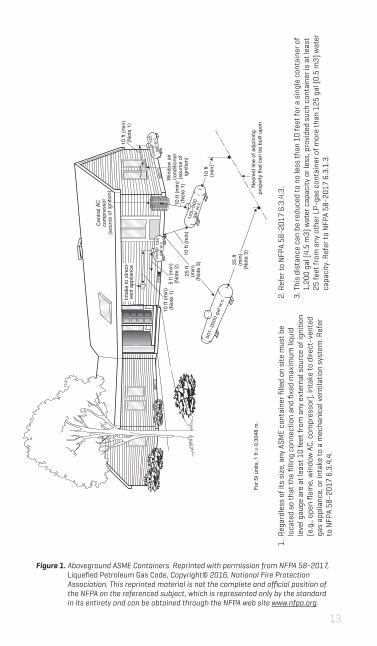
For ASME containers, the distance from any building openings, external sources of ignition, and intakes to direct-vented gas appliances or mechanical ventilation systems are a critical consideration. See Figures 1 and 2 on pages 13 and 14, respectively.
Refer to NFPA 58 for the minimum distances that these containers must be placed from a building or other objects.
13
501–
2000
gal
w.c
.
Und
er 1
25
gal w
.c.
10 ft
(min
)(N
ote
1)
Win
dow
air
cond
ition
er(s
ourc
e of
ig
nitio
n)
10 ft
(m
in)
10 ft
(min
)(N
ote
1)10
ft (m
in)
10 ft
(min
)(N
ote
1)5
ft (m
in)
(Not
e 2)
Inta
ke to
dire
ct-
vent
app
lianc
e
25 ft
(min
)(N
ote
3) 25 ft
(min
)(N
ote
3)
125–
500
gal w
.c.
For S
I uni
ts, 1
ft =
0.3
048
m.
Cen
tral A
Cco
mpr
esso
r(s
ourc
e of
igni
tion)
Und
er 1
25
gal w
.c.
Nea
rest
line
of a
djoi
ning
pr
oper
ty th
at c
an b
e bu
ilt u
pon
1. R
egar
dles
s of
its
size
, any
ASM
E co
ntai
ner fi
lled
on s
ite m
ust b
e lo
cate
d so
that
the
fillin
g co
nnec
tion
and
fixed
max
imum
liqu
id
leve
l gau
ge a
re a
t lea
st 1
0 fe
et fr
om a
ny e
xter
nal s
ourc
e of
igni
tion
(e.g
., op
en fl
ame,
win
dow
AC,
com
pres
sor)
, int
ake
to d
irect
-ven
ted
gas
appl
ianc
e, o
r int
ake
to a
mec
hani
cal v
entil
atio
n sy
stem
. Ref
er
to N
FPA
58-2
017
6.3.
4.4.
Figure 1. Aboveground ASME Containers. Reprinted with permission from NFPA 58-2017, Liquefied Petroleum Gas Code, Copyright© 2016, National Fire Protection Association. This reprinted material is not the complete and official position of the NFPA on the referenced subject, which is represented only by the standard in its entirety and can be obtained through the NFPA web site www.nfpa.org.
2. R
efer
to N
FPA
58-2
017
6.3.
4.3.
3. T
his
dist
ance
can
be
redu
ced
to n
o le
ss th
an 1
0 fe
et fo
r a s
ingl
e co
ntai
ner o
f 1,
200
gal (
4.5
m3)
wat
er c
apac
ity o
r les
s, p
rovi
ded
such
con
tain
er is
at l
east
25
feet
from
any
oth
er L
P-ga
s co
ntai
ner o
f mor
e th
an 1
25 g
al (0
.5 m
3) w
ater
ca
paci
ty. R
efer
to N
FPA
58-2
017
6.3.
1.3.

14 15
Cen
tral A
Cco
mpr
esso
r(s
ourc
e of
igni
tion)
Inta
ke to
dire
ct-
vent
app
lianc
e
Win
dow
air
cond
ition
er(s
ourc
e of
igni
tion)
2000
gal
w.c.
or le
ss
10 ft
(min
)(N
ote
1)
10 ft
(min
)(N
ote
2)10
ft (m
in)
(Not
e 1)
For S
I uni
ts, 1
ft =
0.3
048
m.
10 ft
(min
)(N
ote
1)
Cra
wl s
pace
ope
ning
,w
indo
w, o
r exh
aust
fan
10 ft
(min
)(N
ote
2)
Nea
rest
line
of a
djoi
ning
pro
perty
that
can
be
built
upo
n
Container Location (Continued)
2. N
o pa
rt o
f an
unde
rgro
und
cont
aine
r can
be
less
than
10
feet
fr
om a
n im
port
ant b
uild
ing
or li
ne o
f adj
oini
ng p
rope
rty
that
ca
n be
bui
lt up
on. R
efer
to N
FPA
58-2
017
6.3.
2.3.
Figure 2. Underground ASME Containers. Reprinted with permission from NFPA 58-2017, Liquefied Petroleum Gas Code, Copyright© 2016, National Fire Protection Association. This reprinted material is not the complete and official position of the NFPA on the referenced subject, which is represented only by the standard in its entirety and can be obtained through the NFPA web site www.nfpa.org.
1. T
he re
lief v
alve
, filli
ng c
onne
ctio
n, a
nd fi
xed
max
imum
liqu
id le
vel
gaug
e ve
nt c
onne
ctio
n at
the
cont
aine
r mus
t be
at le
ast 1
0 fe
et
from
any
ext
erio
r sou
rce
of ig
nitio
n, o
peni
ngs
into
dire
ct-v
ent
appl
ianc
es, o
r mec
hani
cal v
entil
atio
n ai
r int
akes
. Ref
er to
NFP
A 58
-201
7 6.
3.4.
4.
15
10 ft
(min
)(N
ote
2)
Cra
wl s
pace
ope
ning
,w
indo
ws,
or e
xhau
st fa
n
Cyl
inde
r fille
d on
si
te a
t the
poi
nt
of u
se fr
om
bulk
truc
k
3 ft
(min
)(N
ote
3)
Win
dow
air
cond
ition
er(s
ourc
e of
ig
nitio
n)
Cen
tral A
Cco
mpr
esso
r(s
ourc
e of
igni
tion)
5 ft
(min
)(N
ote
1)
3 ft
(min
)(N
ote
3)
Cyl
inde
rs n
ot fi
lled
on s
iteat
the
poin
t of u
se
Inta
ke to
dire
ct-
vent
app
lianc
e
5 ft
(min
)(N
ote
1)
For S
I uni
ts, 1
ft =
0.3
048
m.
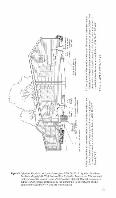
1. F
ive
feet
min
imum
from
relie
f val
ve in
any
dire
ctio
n aw
ay fr
om a
ny
exte
rior s
ourc
e of
igni
tion,
ope
ning
s in
to d
irect
-ven
t app
lianc
es,
or m
echa
nica
l ven
tilat
ion
air i
ntak
es. R
efer
to N
FPA
58-2
017
Ta
ble
6.3.
4.3.
Container Location (Continued)
Figure 3. Cylinders. Reprinted with permission from NFPA 58-2017, Liquefied Petroleum Gas Code, Copyright© 2016, National Fire Protection Association. This reprinted material is not the complete and official position of the NFPA on the referenced subject, which is represented only by the standard in its entirety and can be obtained through the NFPA web site www.nfpa.org.
2. If
the
cylin
der i
s fil
led
on s
ite a
t the
poi
nt o
f use
from
a c
argo
tank
mot
or
vehi
cle,
the
fillin
g co
nnec
tion
and
vent
val
ve m
ust b
e at
leas
t 10
feet
from
an
y ex
terio
r sou
rce
of ig
nitio
n, o
peni
ngs
into
dire
ct-v
ent a
pplia
nces
, or
mec
hani
cal v
entil
atio
n ai
r int
akes
. Ref
er to
NFP
A 58
-201
7 6.
3.4.
4.
3. R
efer
to N
FPA
58-2
017
to 6
.3.4
.3
16 17
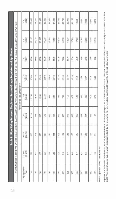
Tabl
e 6.
Pip
e Si
zing
Bet
wee
n Si
ngle
- or S
econ
d-St
age
Regu
lato
r and
App
lianc
eM
AXIM
UM
UN
DIL
UTE
D P
ROPA
NE
CAPA
CITI
ES B
ASED
ON
AN
INLE
T PR
ESSU
RE O
F 11
INCH
ES W
.C. A
ND
A P
RESS
URE
DRO
P OF
0.5
INCH
W.C
. (BA
SED
ON
A 1
.50
SPEC
IFIC
GRA
VITY
GAS
)
Nom
inal
Pip
e Si
ze, S
ched
ule
40
Pipi
ng L
engt
h, F
eet
1/2
in.
(0.6
22)
3/4
in.
(0.8
24)
1 in
.(1
.049
)1-
1/4
in.
(1.3
80)
1-1/
2 in
.(1
.610
)2
in.
(2.0
67)
3 in
.(3
.068
)4
in.
(4.0
26)
1029
160
81,
150
2,35
03,
520
6,79
019
,100
39,0
00
2020
041
878
71,
620
2,42
04,
660
13,1
0026
,800
3016
033
663
21,
300
1,94
03,
750
10,6
0021
,500
4013
728
754
11,
110
1,66
03,
210
9,03
018
,400
5012
225
548
098
51,
480
2,84
08,
000
16,3
00
6011
023
143
489
21,
340
2,57
07,
250
14,8
00
8010
121
240
082
11,
230
2,37
06,
670
13,6
00
100
9419
737
276
31,
140
2,20
06,
210
12,7
00
125
8918
534
971
61,
070
2,07
05,
820
11,9
00
150
8417
533
067
71,
010
1,95
05,
500
11,2
00
200
6714
026
554
381
41,
570
4,42
09,
010
250
6212
924
350
074
91,
440
4,06
08,
290
300
5812
022
746
569
71,
340
3,78
07,
710
350
5110
720
141
261
81,
190
3,35
06,
840
400
4697
182
373
560
1,08
03,
040
6,19
0
Not
e: C
apac
ities
are
in 1
,000
Btu
/Hou
r.
Repr
inte
d w
ith p
erm
issi
on fr
om N
FPA
58-2
017,
Liq
uefie
d Pe
trol
eum
Gas
Cod
e, C
opyr
ight
© 2
016,
Nat
iona
l Fire
Pro
tect
ion
Asso
ciat
ion.
Thi
s re
prin
ted
mat
eria
l is
not t
he c
ompl
ete
and
offici
al p
ositi
on o
f th
e N
FPA
on th
e re
fere
nced
sub
ject
, whi
ch is
repr
esen
ted
only
by
the
stan
dard
in it
s en
tiret
y an
d ca
n be
obt
aine
d th
roug
h th
e N
FPA
web
site
ww
w.n
fpa.
org.

17
Tabl
e 6.
Pip
e Si
zing
Bet
wee
n Si
ngle
- or S
econ
d-St
age
Regu
lato
r and
App
lianc
eM
AXIM
UM
UN
DIL
UTE
D P
ROPA
NE
CAPA
CITI
ES B
ASED
ON
AN
INLE
T PR
ESSU
RE O
F 11
INCH
ES W
.C. A
ND
A P
RESS
URE
DRO
P OF
0.5
INCH
W.C
. (BA
SED
ON
A 1
.50
SPEC
IFIC
GRA
VITY
GAS
)
Nom
inal
Pip
e Si
ze, S
ched
ule
40
Pipi
ng L
engt
h, F
eet
1/2
in.
(0.6
22)
3/4
in.
(0.8
24)
1 in
.(1
.049
)1-
1/4
in.
(1.3
80)
1-1/
2 in
.(1
.610
)2
in.
(2.0
67)
3 in
.(3
.068
)4
in.
(4.0
26)
1029
160
81,
150
2,35
03,
520
6,79
019
,100
39,0
00
2020
041
878
71,
620
2,42
04,
660
13,1
0026
,800
3016
033
663
21,
300
1,94
03,
750
10,6
0021
,500
4013
728
754
11,
110
1,66
03,
210
9,03
018
,400
5012
225
548
098
51,
480
2,84
08,
000
16,3
00
6011
023
143
489
21,
340
2,57
07,
250
14,8
00
8010
121
240
082
11,
230
2,37
06,
670
13,6
00
100
9419
737
276
31,
140
2,20
06,
210
12,7
00
125
8918
534
971
61,
070
2,07
05,
820
11,9
00
150
8417
533
067
71,
010
1,95
05,
500
11,2
00
200
6714
026
554
381
41,
570
4,42
09,
010
250
6212
924
350
074
91,
440
4,06
08,
290
300
5812
022
746
569
71,
340
3,78
07,
710
350
5110
720
141
261
81,
190
3,35
06,
840
400
4697
182
373
560
1,08
03,
040
6,19
0
Not
e: C
apac
ities
are
in 1
,000
Btu
/Hou
r.
Repr
inte
d w
ith p
erm
issi
on fr
om N
FPA
58-2
017,
Liq
uefie
d Pe
trol
eum
Gas
Cod
e, C
opyr
ight
© 2
016,
Nat
iona
l Fire
Pro
tect
ion
Asso
ciat
ion.
Thi
s re
prin
ted
mat
eria
l is
not t
he c
ompl
ete
and
offici
al p
ositi
on o
f th
e N
FPA
on th
e re
fere
nced
sub
ject
, whi
ch is
repr
esen
ted
only
by
the
stan
dard
in it
s en
tiret
y an
d ca
n be
obt
aine
d th
roug
h th
e N
FPA
web
site
ww
w.n
fpa.
org.
Tabl
e 7.
Max
imum
Cap
acit
y of
CSS
T1
EHD
2 FLO
W
DES
IGN
ATIO
N
IN T
HOU
SAN
DS
OF B
TU/H
OUR
OF U
ND
ILU
TED
PRO
PAN
E AT
A P
RESS
URE
OF
11 IN
CHES
W.C
. AN
D A
PRE
SSU
RE D
ROP
OF 0
.5 IN
CH W
.C.
( BAS
ED O
N A
1.5
0 SP
ECIF
IC G
RAVI
TY G
AS)
Tubi
ng L
engt
h, F
eet
510
1520
2530
4050
6070
8090
100
150
200
250
300
1372
5039
3430
2823
2019
1715
1514
119
88
1599
6955
4942
3933
3026
2523
2220
1514
1211
1818
112
910
491
8274
6458
5349
4544
4131
2825
23
1921
115
012
110
694
8774
6660
5752
5047
3633
3026
2335
525
420
818
316
415
113
111
810
799
9490
8566
6053
50
2542
630
324
821
619
217
715
313
712
611
710
910
298
7569
6157
3074
452
142
236
532
529
725
622
720
719
117
816
915
912
311
299
90
3186
360
549
042
537
934
429
726
524
122
220
819
718
614
312
911
710
7
1 Tab
le in
clud
es lo
sses
for f
our 9
0° b
ends
and
two
end
fittin
gs. T
ubin
g ru
ns w
ith la
rger
num
bers
of b
end
and/
or fi
ttin
gs s
hall
be in
crea
sed
by a
n eq
uiva
lent
le
ngth
of t
ubin
g to
the
follo
win
g eq
uatio
n: L
= 1
.3n
whe
re L
is th
e ad
ditio
nal l
engt
h (f
eet)
of t
ubin
g an
d n
is th
e nu
mbe
r of a
dditi
onal
fitt
ings
and
/or b
ends
.2 EH
D (E
quiv
alen
t Hyd
raul
ic D
iam
eter
) is
a m
easu
re o
f the
rela
tive
hydr
aulic
effi
cien
cy b
etw
een
diff
eren
t tub
ing
size
s. T
he g
reat
er th
e va
lue
of E
HD,
the
grea
ter
the
gas
capa
city
of t
he tu
bing
.
Repr
inte
d w
ith p
erm
issi
on fr
om N
FPA
58-2
017,
Liq
uefie
d Pe
trol
eum
Gas
Cod
e, C
opyr
ight
© 2
016,
Nat
iona
l Fire
Pro
tect
ion
Asso
ciat
ion.
Thi
s re
prin
ted
mat
eria
l is
not t
he c
ompl
ete
and
offici
al p
ositi
on
of th
e N
FPA
on th
e re
fere
nced
sub
ject
, whi
ch is
repr
esen
ted
only
by
the
stan
dard
in it
s en
tiret
y an
d ca
n be
obt
aine
d th
roug
h th
e N
FPA
web
site
ww
w.n
fpa.
org.

18 19
Figure 4.Interior Gas Piping Inlet Positioning Guidelines
Gas Piping Inlet PositioningJust like tanks, propane pressure regulators come with requirements regarding pipe size and installation distance. Regulators installed on the gas piping system at the side of buildings cannot be placed closer than three feet horizontally from any building opening, such as a window well, that’s lower than the installed regulator. Nor can they be placed closer than five feet from any source of ignition, such as an AC compressor or the intake to a direct-vent appliance. Additional regulations, as well as regulator manufacturer’s instructions, may apply. Check with a propane professional first to ensure you comply with interior gas piping inlet positioning requirements.

19
Gas Piping Hangers, Supports, and AnchorsThese guidelines cover the placement of gas piping hangers, supports, and anchors, and have been adapted with permission from NFPA 54-2018, the National Fuel Gas Code. NFPA 54, local codes and standards, and manufacturer recommendations should be observed at all times.
Piping shall be supported with metal pipe hooks, metal pipe straps, metal bands, metal brackets, metal hangers, or building structural components, suitable for the size of the piping, of adequate strength and quality, and located at intervals so as to prevent or damp out excessive vibration. Piping shall be anchored to prevent undue strains on connected appliances and equipment and shall not be supported by other piping. Pipe hangers and supports shall conform to the requirements of ANSI/MSS SP-58, Pipe Hangers and Supports — Materials, Design, Manufacture, Selection, Application, and Installation.
Spacings of supports in gas piping installations shall not be greater than shown in Table 8.
Spacing of supports of CSST shall be in accordance with the CSST manufacturer’s instructions.
Supports, hangers, and anchors shall be installed so as not to interfere with the free expansion and contraction of the piping between anchors. All parts of the supporting system shall be designed and installed so they are not disengaged by movement of the supported piping.
Reprinted with permission from NFPA 54-2018, National Fuel Gas Code, Copyright© 2017, National Fire Protection Association. This reprinted material is not the complete and official position of the NFPA on the referenced subject, which is represented only by the standard in its entirety and can be obtained through the NFPA web site www.nfpa.org.
Table 8. Support of Piping
Steel Pipe, Nominal Size of Pipe (Inches)
Spacing of Supports (Feet)
Nominal Size of Tubing Smooth Wall (Inches O.D.)
Spacing of Supports (Feet)
1/2 6 1/2 4
3/4 or 1 8 5/8 or 3/4 6
1-1/4 or larger (horizontal)
10 7/8 or 1 (horizontal)
8
1-1/4 or larger (vertical)
Every floor level 1 or larger (vertical)
Every floor level

20 21
The Propane-Ready HomeA home can be made propane-ready with simple steps like installing gas piping (CSST or alternative) to future use points, installing a manifold with available ports, and roughing in for future applications, such as by using a generator-ready electric panel. These steps add value to the home and pave the way for more propane applications. The house cutaway below shows use points for propane to consider both inside and outside the home.
Figure 5. The Propane-Ready Home
A. Clothes drying
B. Cooking
C. Space heating
D. Water heating
E. Backup power
F. Outdoor kitchen and amenities
G. Future flexibility
H. Fireplace
I. Pool heating
J. Snowmelt
I
J
HB
C D
E
F
G
A

21
Propane Generator Installation
1. Propane generators are available up to 400kW and some models can be tied together for increased capacity. Refer to manufacturer specifications for guidance on larger generator sizes.
2. Generator manufacturers and models may have varying Btu requirements. Check manufacturer specifications for guidance.
3. Generator Btu load may require separate second-stage propane regulation. The propane system installer will make that determination based on total Btu load of the project.
Diagram and chart based on information provided courtesy of Generac.
Figure 6. Propane Generator Installation Diagram
8
11
13
14
15
17
20
22
25
27
30
36
45
48
60
70
80
100
130
150
129,000
175,000
268,000
279,000
260,000
325,000
350,000
313,000
430,000
356,000
493,000
500,000
725,000
755,000
818,000
1,028,000
1,163,000
1,268,000
1,798,000
2,075,000
79,000
107,000
149,000
168,000
166,000
181,000
189,000
188,000
298,000
195,000
320,000
280,000
378,000
393,000
458,000
503,000
603,000
718,000
933,000
1,078,000
GeneratorkW Rating
Fuel Consumption at 100% Btu/Hour
Fuel Consumption at 50% Btu/Hour
Table 9. Propane Generator Fuel Consumption 1,2,3
Flex fuel line
Size gas pipe from secondary regulator with generator sizing guide or to local codes.
Safety shut-offwith pressure port
Secondary regulator vented 5 feet from generator
High-pressure pipesized per propane provider
Check distance with propane provider
Connection to propane storage
22 23
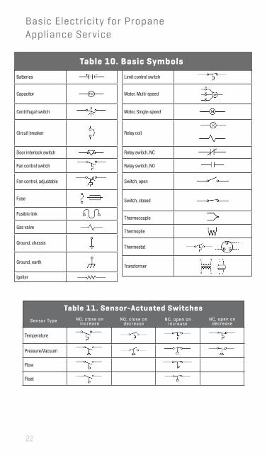
Basic Electricity for Propane Appliance Service
Q U I C K R E F E R E N C E G U I D E
Table of Symbols
Batteries Limit control switch
Capacitor Fan Motor, Multi-speed
Centrifugal switch Motor, Single-speed
Circuit breaker Relay coil
Door interlock switch Relay switch, NC
Fan control switch Relay switch, NO
Fan control, adjustable Switch, open
Fuse
Switch, closed
Fusible link Thermocouple
Gas valve Thermopile
Ground, chassis Thermostat
Ground, earth Transformer
Igniter
Sensor-Actuated Switches
Sensor TypeNO, close on
increaseNO, close on
decreaseNC, open on
increaseNC, open on
decrease
Temperature
Pressure/Vacuum
Flow
Float
Basic Electricity for Propane Appliance Service
Sensor Type NO, close onincrease
Table 11. Sensor-Actuated SwitchesNO, close on
decreaseNC, open on
increaseNC, open on
decrease
Table 10. Basic Symbols

23
Ohm’s Law
Volts = Amps X Ohms
Watt’s Law
Power (Watts) = Volts X Amps
VOLTAGE READINGSMillivolts: 1 mV = .001 VVolts: 1 V = 1 volt
RESISTANCE READINGSMilli-ohms: 1 mW = .001 WOhms: 1 W = 1 ohmKiloohms or kilo-ohms: 1 kW = 1,000 WMegohms or mega-ohms: 1 MW = 1,000,000 W
CURRENT READINGSMicroamps: 1 μA = .000001 AMilliamps: 1 mA = .001 A Amps: 1 A = 1 amp
Series Circuit
Load1
L1 N120 Volts
Load2
15 Ω 20 Ω
Load3
25 Ω
• Voltage drops from one load to the next.• Current is constant throughout the circuit.• Resistance of circuit is sum of the resistances of the loads in the
circuit.
Parallel Circuit
L1 N
Motor
A = 24
A = 6
120 Volts
120 Volts
20 Ω
5 ΩB
C
• Full source voltage is delivered to each branch in a parallel circuit.• Total current for a parallel circuit is the sum of the current
amounts for each branch in the circuit.• Total resistance for a parallel circuit is source voltage divided by
total current for the circuit, or:
240 Volt Circuit
L1 L2 N
120 Volts
120 Volts240 Volts
Load3
Load1
Load2
GND
Polarity Check
L1 N120 Volts
120 Volts 0 Volts
Load
GND
RT =1R1
1R2
+ + ... 1Rn
1
24 25
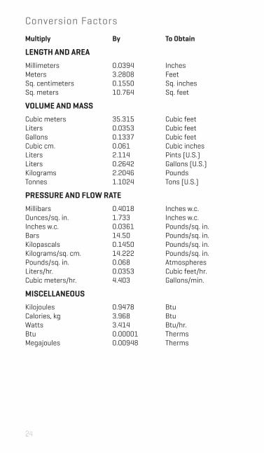
Conversion Factors
Multiply By To Obtain
LENGTH AND AREA
MillimetersMetersSq. centimetersSq. meters
0.03943.28080.155010.764
InchesFeetSq. inchesSq. feet
VOLUME AND MASS
Cubic metersLitersGallonsCubic cm.LitersLitersKilogramsTonnes
35.3150.03530.13370.0612.1140.26422.20461.1024
Cubic feetCubic feetCubic feetCubic inchesPints (U.S.)Gallons (U.S.)PoundsTons (U.S.)
PRESSURE AND FLOW RATE
MillibarsOunces/sq. in.Inches w.c.BarsKilopascalsKilograms/sq. cm.Pounds/sq. in.Liters/hr.Cubic meters/hr.
0.40181.7330.036114.500.145014.2220.0680.03534.403
Inches w.c.Inches w.c.Pounds/sq. in.Pounds/sq. in.Pounds/sq. in.Pounds/sq. in.AtmospheresCubic feet/hr.Gallons/min.
MISCELLANEOUS
KilojoulesCalories, kgWattsBtuMegajoules
0.94783.9683.4140.000010.00948
BtuBtuBtu/hr.ThermsTherms
25
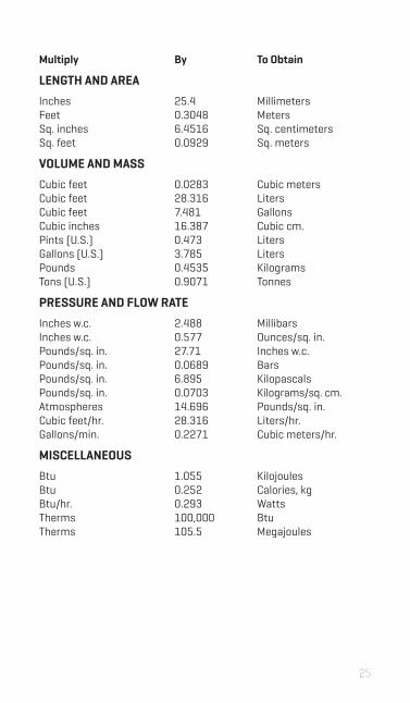
Multiply By To Obtain
LENGTH AND AREA
InchesFeetSq. inchesSq. feet
25.40.3048 6.4516 0.0929
MillimetersMetersSq. centimetersSq. meters
VOLUME AND MASS
Cubic feetCubic feetCubic feetCubic inchesPints (U.S.)Gallons (U.S.)PoundsTons (U.S.)
0.028328.3167.48116.3870.4733.7850.45350.9071
Cubic metersLitersGallonsCubic cm.LitersLitersKilogramsTonnes
PRESSURE AND FLOW RATE
Inches w.c.Inches w.c.Pounds/sq. in.Pounds/sq. in.Pounds/sq. in.Pounds/sq. in.AtmospheresCubic feet/hr.Gallons/min.
2.4880.57727.710.06896.8950.070314.69628.3160.2271
MillibarsOunces/sq. in.Inches w.c.BarsKilopascalsKilograms/sq. cm.Pounds/sq. in.Liters/hr.Cubic meters/hr.
MISCELLANEOUS
BtuBtuBtu/hr.ThermsTherms
1.0550.2520.293100,000105.5
KilojoulesCalories, kgWattsBtuMegajoules

BUIL DW I T HP ROPA NE .COM2 02 . 4 52 .8 975INFO@P ROPA NE .COM© 2 0 1 8 b y t h e P r o p a n e E d u c a t i o n & R e s e a r c h C o u n c i l 5 0 4 1- B R -1 3
TECHNICAL POCKET GUIDE