THE PRODUCTS THE QUALITY
61
THE COMPANY THE QUALITY THE PRODUCTS
Transcript of THE PRODUCTS THE QUALITY

THE COMPANY
THE QUALITY
THE PRODUCTS

Idromec S.r.l. was set up in Brescia on November 10th, 1979 and it’s the youngest among the Italian companiesproducing water pumps.
Idromec is today composed by a well prepared and motivated managerial team, supported by a qualified staff, in all strategic areas of the company, Idromec is also a company that can be proud of its modern numerical control machines.
Our footprint goes from creativity and flexibility typically Italian, to the unceasing development of innovative solutions, until the most advanced technological research pursued it total quality in every detail made it possible by our enthusiasm and teamwork.
Idromec certifications are not limited to ISO (after acquiring the 9001-2000 we started TS 16949:2002 certification) but also involve a constant process of self-analysis by testing 100% of our products.
In a specialized laboratory internal to the company measurements and tests are made in every single phase of the process, this methods permits us to keep under control all we produce. Our products emblematically represents Idromec new route as well, they are an essential part of the engine, as well as of its performance and life. Our products plays a crucial role in the engine safety for this reason the process of incessant improvement of quality and safety is for us one of the most important goal.
Reliability, product quality and client service flexibility, in every part of the world, are the cornerstones of our company.
2© Idromec S.r.l.

MANAGEMENT PROCESSES
MANAGEMENTRESOURCE
MANAGEMENT
QUALITYMANAGEMENT
SYSTEM
SUPPORT PROCESSES
MAINTENANCEPURCHASING LABORATORYSALES FEEDBACKMEASUREMENT, ANALYSIS AND IMPROVEMENT
PRODUCTION
PRODUCTION PLANNINGSALES
SUPPLIERS
DESIGN AND DEVELOPMENT
PACKAGING AND DELIVERY
BUSINESS PROCESSES: OUR IDEA OF SYNERGY
3

QUALITY POLICY MANAGEMENT
4
IDROMEC S.r.l. top management establish the following quality policy which is the line of business strategy and is summarized inthe following general objectives:
full customer satisfaction
continual improvement of processes and products
abidance with statutory and regulatory requirements
consolidation of its image
Top management identify the following points as the guide lines for achieving such objectives:
effectiveness and efficiency of the processes and of the quality management system
clear definition of responsibilities and tasks, as a support to a multidisciplinary approach
an effective monitoring and management of possible non conformities
prevention of potential non conformities through planning activities and FMEA
prompt reply to customer requirements regarding new products development
flexibility of production and adherence to delivery lead time required by customers
effective management of purchasing process
motivation and responsibilization of personnel
continuous attention to training for personnel

ISO/TS 16949:2009
On December 2009, our company passed the periodical quality management system re-assessment and fulfilled the transition toISO 9001:2008 standard.
Implementation of the ISO/TS 16949:2009 automotive specifications is currently in progress, with the cooperation of the qualityassurance managers of various group companies and the assistance by an external consulting office.
CERTIFICATIONSQUALITY
MANAGEMENT SYSTEM
5

Today, with a covered production area of almost 5000 m2, our catalogue includes a collection of 720 references.
PRODUCTION DEPARTMENTS LAYOUTRESOURCE
MANAGEMENT
6© Idromec S.r.l. 6
MACHINING
ASS
EMB
LYA
ND
TES
T
PACKAGING AND DELIVERY
FINISHED PRODUCTS WAREHOUSE
OFF
ICES
TEST ROOM METROLOGY LAB
INC
OM
ING
G
OO
DS
FINISHED PRODUCT
MACHINING TOOLINGS
CO
MP
ON
ENTS
W
AR
EHO
USE
RAW BODIES WAREHOUSE
MACHINED BODIES W.H.
WAREHOUSE
COMPONENTS

THE CUSTOMER SALES
7
Our sales office is composed of a young and dynamic staff,skilled and motivated.
Customer satisfaction is our first objective and the lifeblood ofour work.
Each customer is unique, with his requirements and peculiarity,and we aim to establish with each one a relationship where weare judged by what we do and not by what we say.
Efficiency, punctuality and an extreme flexibility are thefoundation of the service that we offer to our customers,everywhere in the world.
Offers
Order confirmations
New products
Offer requests
Technical
specifications
Orders
SALES

Without the customer drawings, the design of an aftermarketproduct follows the form, fit & function principle.
Through the reverse engineering of the original sample we buildthe tridimensional model of the pump: in this way we guaranteedimensional equivalency and interchangeability. Performanceequivalency is verified by comparison of the characteristiccurves, detected on the test bench in our laboratory, and by allthe tests forecasted by Fiat Auto specifications (9.02320/01).
The different phases of the product and process design, fromthe feasibility analysis up to the final validation, are plannedand monitored through the APQP, periodically reviewed by themultidisciplinary team with respect to the activities proceedingand timing.
PRODUCTDESIGN
DESIGN AND DEVELOPMENT
8

PRODUCT VALIDATION LABORATORY
9
At the end of the design planning, product validation is carried out accordingto Fiat Auto specifications (9.02320/01).
Static leak test at room temperature
Static leak test at -20°C
Dynamic leak test at 90°C
Performance test at room temperature
Performance test at 90°C
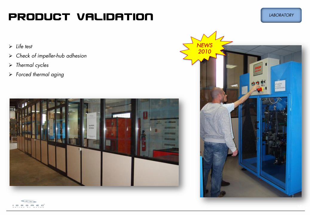
PRODUCT VALIDATION LABORATORY
NEWS2010
10
Life test
Check of impeller-hub adhesion
Thermal cycles
Forced thermal aging

The “Specifications for the quality of supplies” outlines thegeneral principles designing the relations between Idromec andits suppliers, with the primary objective to maintain and developa network of suppliers able to guarantee the integrity andreliability of the supplied materials, components and products.
Idromec policy contemplates exclusively contractual relationswith qualified suppliers.Quality Assurance of Idromec is liable for the qualification ofpotential suppliers, for monitoring and for the audits on theapproved suppliers..
Suppliers are qualified by Idromec in keeping with thefollowing principles considered alternatives:
certification ISO/TS 16949:2009
certification ISO 9001:2008 + automotive requirements
audit by Idromec
SUPPLIERS QUALIFICATION
11
PURCHASING

12
Suppliers, before starting the mass production, must obtain the approval from Idromec.This approval is subject to the submission of samples according to Idromec PPAP, which is summarized in the elements/documents listed in the table.The assignment of the level for the sampling submission is established according to the type/criticality of the product and to the capability of the supplier.
METHODS / DOCUMENTSLevel
1 2
PART SUBMISSION WARRANT X X
SAMPLES X X
DIMENSIONAL RESULTS X X
PERFORMANCE RESULTS (if provided in the drawing) X X
MATERIAL RESULTS X X
TOOLING REPORT (when requested) X X
FLOW-CHART X
CONTROL PLAN X
PFMEA X
INITIAL PROCESS STUDIES (Cp/Cpk) X
MEASUREMENT SYSTEM ANALYSIS STUDIES X
COMPONENTS QUALIFICATION LABORATORY

13
INSPECTION OF INCOMING GOODS PRODUCTION
Incoming goods are identified with a tag, waiting for inspection.The control plan establish the methods and the quantities to beinspected.Only after QC has signed the tag, goods can be used.

MACHINING PRODUCTION
14
n. 2 CNC working centers CHIRON FZ18W
4 controlled axis (x,y,z + rotating table)
automatic pallet change
productivity up to 100 pcs/h
n. 1 CNC working center TRAUB TVC350P
3 controlled axis
automatic pallet change
NEWS2010
15
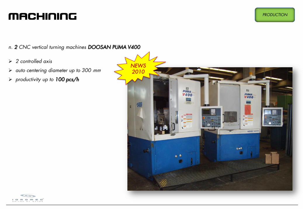
MACHINING PRODUCTION
n. 2 CNC vertical turning machines DOOSAN PUMA V400
2 controlled axis
auto centering diameter up to 300 mm
productivity up to 100 pcs/h
16
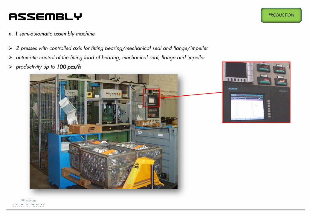
ASSEMBLY PRODUCTION
n. 1 semi-automatic assembly machine
2 presses with controlled axis for fitting bearing/mechanical seal and flange/impeller
automatic control of the fitting load of bearing, mechanical seal, flange and impeller
productivity up to 100 pcs/h
17
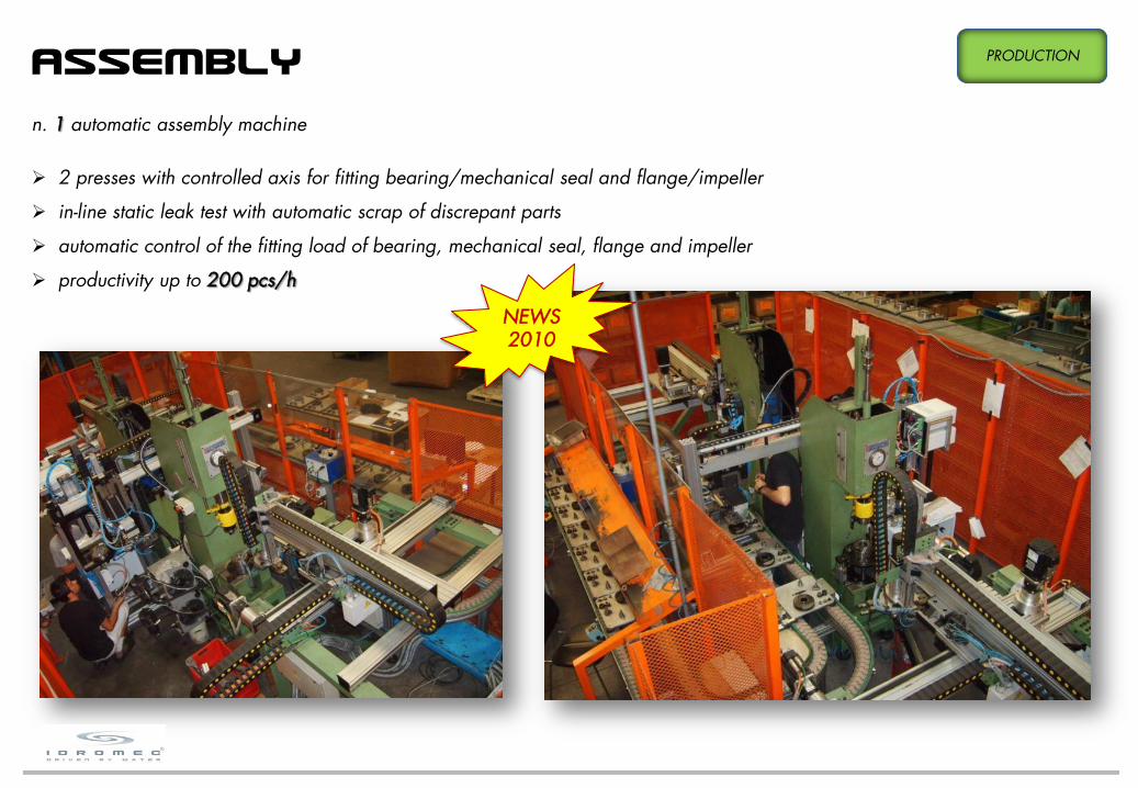
n. 1 automatic assembly machine
2 presses with controlled axis for fitting bearing/mechanical seal and flange/impeller
in-line static leak test with automatic scrap of discrepant parts
automatic control of the fitting load of bearing, mechanical seal, flange and impeller
productivity up to 200 pcs/h
ASSEMBLY PRODUCTION
NEWS2010

18
After assembly pumps are 100% leak-tested with a special machine for testing the absence of leaks.An automated control will detect discrepant parts and automatically lock them in station to prevent further processing; test successis shown by a green spot on the body pump.
LEAK TEST PRODUCTION

MARKING, PACKAGING AND DELIVERYPACKAGING AND
DELIVERY
19
Marking of water pumps is made with permanent ink-jet markers: it’s possible to realize personalized brands with logos and text,according to the customer specifications.Packaging is agreed with customer as well and the components to be added in box are managed through a computer, allowingthe chance to replace the standard components with a personalized warranty or instructions.

METROLOGY LAB LABORATORY
20© Idromec S.r.l. 20
MEASUREMENT CAPABILITY OF THE LABORATORY:
3D coordinate measuring machine WERTH SCOPE-CHECK
Roundness, concentricity, radial runout
Hardness Rockwell A, B, C
Roughness
Coating thickness
Vibrations (integral shaft bearings)
Flatness of lapped surfaces
Precision balance

APPENDIXA - MATERIALS
22
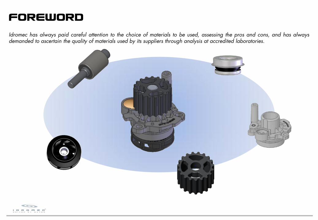
FOREWORD
Idromec has always paid careful attention to the choice of materials to be used, assessing the pros and cons, and has alwaysdemanded to ascertain the quality of materials used by its suppliers through analysis at accredited laboratories.
23
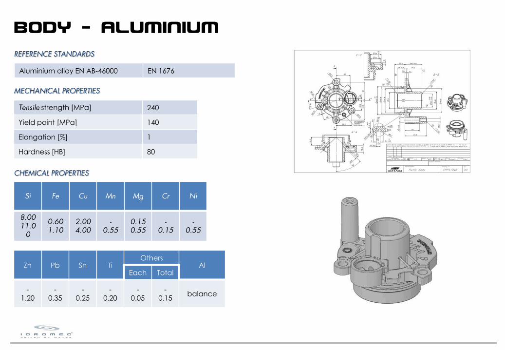
Si Fe Cu Mn Mg Cr Ni
8.0011.0
0
0.601.10
2.004.00
-0.55
0.150.55
-0.15
-0.55
REFERENCE STANDARDS
MECHANICAL PROPERTIES
CHEMICAL PROPERTIES
Tensile strength [MPa] 240
Yield point [MPa] 140
Elongation [%] 1
Hardness [HB] 80
Aluminium alloy EN AB-46000 EN 1676
BODY - ALUMINIUM
Zn Pb Sn TiOthers
AlEach Total
-1.20
-0.35
-0.25
-0.20
-0.05
-0.15
balance

24
C * Si * Cr * S P Fe *
3.203.50
2.002.50
-0.20
-0.15
-0.10
balance
* not boundary
REFERENCE STANDARDS
MECHANICAL PROPERTIES
CHEMICAL PROPERTIES
Tensile strength [MPa] 250
Cast Iron GH 190 Fiat Auto 52205
Cast Iron GH 190 Iveco Std. 15-2220
Cast Iron EN-GJL-250 EN 1561
BODY - CAST IRON
25
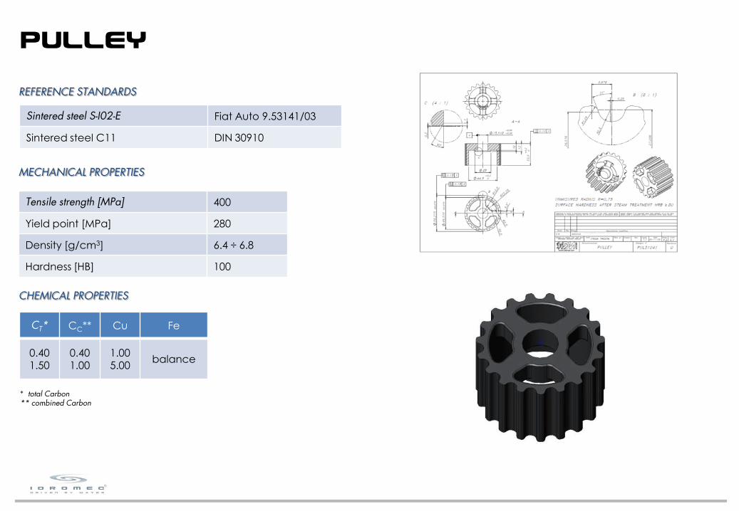
CT* CC** Cu Fe
0.401.50
0.401.00
1.005.00
balance
REFERENCE STANDARDS
MECHANICAL PROPERTIES
CHEMICAL PROPERTIES
Sintered steel S-I02-E Fiat Auto 9.53141/03
Sintered steel C11 DIN 30910
* total Carbon** combined Carbon
Tensile strength [MPa] 400
Yield point [MPa] 280
Density [g/cm3] 6.4 ÷ 6.8
Hardness [HB] 100
PULLEY

26
C Mn Si P S Pb Fe
-0.14
1.001.50
-0.05
-0.11
0.340.40
0.200.35
balance
REFERENCE STANDARDS
MECHANICAL PROPERTIES
CHEMICAL PROPERTIES
Tensile strength [MPa] 400 ÷ 650
Yield point [MPa] 305
Elongation [%] 9
Steel 11SMnPb37 EN 10277-3
FLANGE

27
PA66-GF30 PPS-GF40
T of deflection under load [°C] 250 270
Density [g/cm3] 1.36 1.66
Tensile stress @ break [MPa] 175 210
Flexural strength [MPa] 280 290
BOTH THESE MATERIALS ARE USED BY MAJOR CAR MANUFACTURERS, SO ITGOES WITHOUT SAYING THAT THEY ARE APPROPRIATE FOR ITS INTENDEDUSE IN NORMAL OPERATING CONDITIONS. THE SAME MATERIALS AREUSED FOR THEIR CHEMICAL AND HEAT RESISTANCE, AS WELL AS EXCELLENTDIMENSIONAL STABILITY, FOR THE CONSTRUCTION OF FUEL SUPPLYSYSTEMS.
MECHANICAL PROPERTIES
REFERENCE STANDARDS
Nylon 6,6 >PA66-GF30< * EN ISO 11469
Polyphenylsulfide >PPS-GF40< ** EN ISO 11469
* nylon 6,6 reinforced with 30% fiber glass** polyphenylsulfide reinforced with 40% fiber glass
IMPELLER
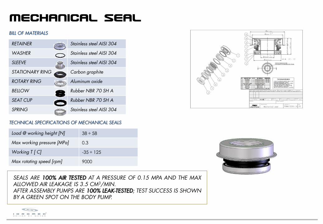
BILL OF MATERIALS
RETAINER Stainless steel AISI 304
WASHER Stainless steel AISI 304
SLEEVE Stainless steel AISI 304
STATIONARY RING Carbon graphite
ROTARY RING Aluminum oxide
BELLOW Rubber NBR 70 SH A
SEAT CUP Rubber NBR 70 SH A
SPRING Stainless steel AISI 304
TECHNICAL SPECIFICATIONS OF MECHANICAL SEALS
Load @ working height [N] 38 ÷ 58
Max working pressure [MPa] 0.3
Working T [°C] -35 ÷ 125
Max rotating speed [rpm] 9000
SEALS ARE 100% AIR TESTED AT A PRESSURE OF 0.15 MPA AND THE MAXALLOWED AIR LEAKAGE IS 3.5 CM3/MIN.AFTER ASSEMBLY PUMPS ARE 100% LEAK-TESTED; TEST SUCCESS IS SHOWNBY A GREEN SPOT ON THE BODY PUMP.
28
MECHANICAL SEAL

BILL OF MATERIALS
SHAFT Steel 100Cr6
OUTER RING Steel 100Cr6
SEAL Rubber NBR 70 SH A
BALLS Steel 100Cr6
ROLLERS Steel 100Cr6
CAGES Nylon 6,6 >PA66-GF25<
TECHNICAL SPECIFICATIONS OF BEARINGS
Radial play [mm] 0.020 ÷ 0.035
Axial play [mm] 0.020 ÷ 0.035
Grease working T [°C] -40 ÷ 180
Load capacity [N] according to drawing
DURING ASSEMBLY BEARINGS ARE 100% CHECKED WITH ANAUTOMATED CONTROL OF THE FITTING LOAD IN ORDER TOAVOID FAILURE OF THE BEARING BECAUSE OF TOO TIGHT ORTOO LOOSE FIT.
29
BEARING

APPENDIX B - WAYS OF FAILURE

31
1. LIMITING POTENTIAL FAILURE MODES
Potential failure modes are limited through very strict controls during all production process. Quality of supplies is constantlymonitored according to our specifications, which ensure compliance with the highest standards; we cooperate with our mainsuppliers in setting quality goals, with a view to a continuous improvement, according to our quality policy.The most severe potential failure modes which affects water pumps are:
failure of the bearing because of too tight or too loose fit: to avoid this, when we machine the body we strictly abide with thetolerances prescribed by bearings manufacturers and when we assembly the pump, an automated control of the fitting load willdetect discrepant parts and automatically lock them
in station to prevent further processing.According to the last 3 years quality records, occurrence of this failure mode is around250 ppm and detection is 100%.
leakage because of defective mechanical seal: to avoid this, after assembly pumps are100% leak-tested; an automated control will detect discrepant parts and automatically lockthem in station to prevent further processing; test success is shown by a green spot on thebody pump.According to the last 3 years quality records, occurrence of this failure mode is around3000 ppm and detection is around 97%.
FOREWORD

32
hydrodynamic film
coolant
stationary ring
rotary ring
2. MECHANICAL FACE SEALS
In a mechanical face seal, sealing is assured by the faces of two rings sliding on each other under the pressure of a spring. Thestationary ring, usually made by graphite, is integral with the pump body, whereas the rotary ring, usually made by ceramic, isintegral with the bearing shaft. The faces are lapped to obtain a flatness within 2 µm and high-density pressed to avoid earlywear. A thin film of coolant always need to be present between the two faces: it takes away heat generated by friction and, at thesame time, it acts as a lubricant, reducing the friction between the two faces. The most common phenomena which may menacethe correct work of a mechanical seal are:
adhesion, that is the transfer of material from one face to the other - it takes place in the absence of coolant film - or fromparticles circulating through the cooling system such as sealant or dirt
abrasion, that is the scraping of the sliding faces by hard particles circulating through the cooling system such as oxides, dirt orlimestone
thermal fatigue, that is the cyclic elastic deformation of the sliding faces due to thermal stress: it takes place in the absence ofcoolant film

33
3. INTEGRAL SHAFT BEARING
Water pump bearings are double row bearings whose raceways are machined directly into the shaft. They are ready-to-fit bearingunits and they are lubricated for life. The function of the lubricant is to carry away heat, to protect bearing surfaces from corrosion,to reduce friction and to dampen running noise.
The most common phenomena which may menace the correct work of a bearing are:
lubricant contamination: if the mechanical seal is leaking, coolant may seep into the bearing, causing the rolling elements torust with pitting and corrosion, reducing bearing life.
overload: over-tension or misalignment of the belt produce an overload condition on the rolling elements, causing overheatingand reducing bearing life
34
4. GUARANTEE
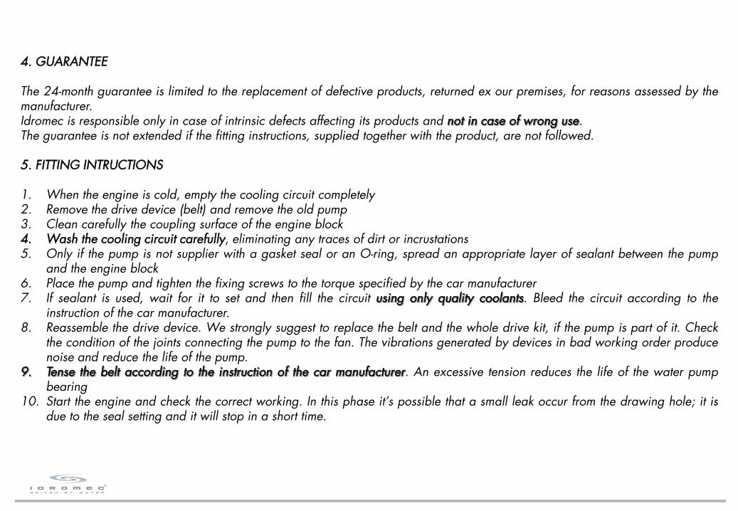
The 24-month guarantee is limited to the replacement of defective products, returned ex our premises, for reasons assessed by themanufacturer.Idromec is responsible only in case of intrinsic defects affecting its products and not in case of wrong use.The guarantee is not extended if the fitting instructions, supplied together with the product, are not followed.
5. FITTING INTRUCTIONS
1. When the engine is cold, empty the cooling circuit completely2. Remove the drive device (belt) and remove the old pump3. Clean carefully the coupling surface of the engine block4. Wash the cooling circuit carefully, eliminating any traces of dirt or incrustations5. Only if the pump is not supplier with a gasket seal or an O-ring, spread an appropriate layer of sealant between the pump
and the engine block6. Place the pump and tighten the fixing screws to the torque specified by the car manufacturer7. If sealant is used, wait for it to set and then fill the circuit using only quality coolants. Bleed the circuit according to the
instruction of the car manufacturer.8. Reassemble the drive device. We strongly suggest to replace the belt and the whole drive kit, if the pump is part of it. Check
the condition of the joints connecting the pump to the fan. The vibrations generated by devices in bad working order producenoise and reduce the life of the pump.
9. Tense the belt according to the instruction of the car manufacturer. An excessive tension reduces the life of the water pumpbearing
10. Start the engine and check the correct working. In this phase it’s possible that a small leak occur from the drawing hole; it isdue to the seal setting and it will stop in a short time.

ABRASION
(incrustations)
DIRT OR INCRUSTATIONSBefore installing any new pump it is necessary to thoroughly flush the cooling system to remove any contaminants. Thesecontaminants could also be the reason for the failure of the original pump.The particles in solution or suspension may damage the sealing surfaces of the mechanical seal which will start to leak. This is whymechanics are advised to wash the cooling system carefully, changing the old fluid and replacing any other rusty or damagedsystem components.
35
In old engines the contamination of coolant may be due also to lack of tightnessin the cylinder head gasket with leakage of combustion gases into the coolingsystem: this modifies both the chemical state and the pressure of the coolant.If the chemical properties of the coolant are modified, it might no longer becompatible with the various materials which make up the cooling system, whichwill fail after a short time.
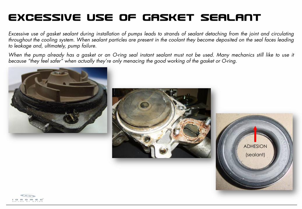
ADHESION
(sealant)
EXCESSIVE USE OF GASKET SEALANTExcessive use of gasket sealant during installation of pumps leads to strands of sealant detaching from the joint and circulatingthroughout the cooling system. When sealant particles are present in the coolant they become deposited on the seal faces leadingto leakage and, ultimately, pump failure.
When the pump already has a gasket or an O-ring seal instant sealant must not be used. Many mechanics still like to use itbecause “they feel safer” when actually they’re only menacing the good working of the gasket or O-ring.
36
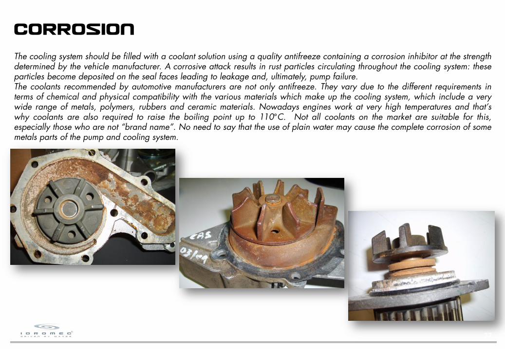
CORROSIONThe cooling system should be filled with a coolant solution using a quality antifreeze containing a corrosion inhibitor at the strengthdetermined by the vehicle manufacturer. A corrosive attack results in rust particles circulating throughout the cooling system: theseparticles become deposited on the seal faces leading to leakage and, ultimately, pump failure.The coolants recommended by automotive manufacturers are not only antifreeze. They vary due to the different requirements interms of chemical and physical compatibility with the various materials which make up the cooling system, which include a verywide range of metals, polymers, rubbers and ceramic materials. Nowadays engines work at very high temperatures and that’swhy coolants are also required to raise the boiling point up to 110°C. Not all coolants on the market are suitable for this,especially those who are not “brand name”. No need to say that the use of plain water may cause the complete corrosion of somemetals parts of the pump and cooling system.
37
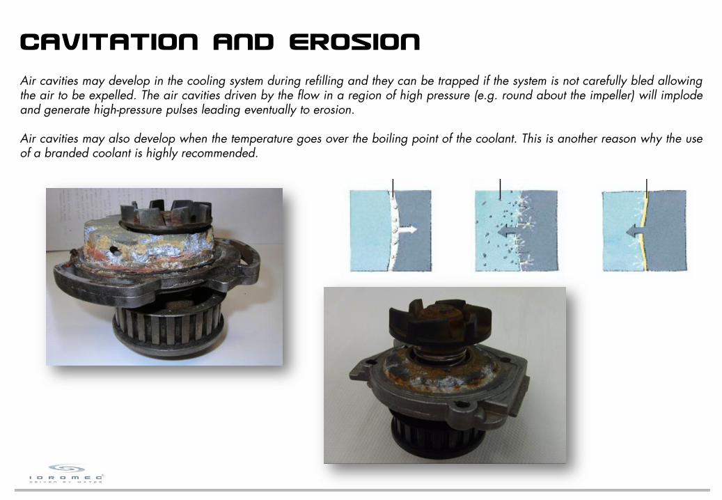
CAVITATION AND EROSIONAir cavities may develop in the cooling system during refilling and they can be trapped if the system is not carefully bled allowingthe air to be expelled. The air cavities driven by the flow in a region of high pressure (e.g. round about the impeller) will implodeand generate high-pressure pulses leading eventually to erosion.
Air cavities may also develop when the temperature goes over the boiling point of the coolant. This is another reason why the useof a branded coolant is highly recommended.
38

ELECTROLYSISElectrolysis is erosion caused by an electrical current generated by dissimilar metals bathed in acidic fluid (pH below 7.0). Whenthis phenomenon takes place the aluminium parts of the cooling system (engine block, water pump) work as the anode: thealuminium undergoes oxidation and it is transferred to the iron parts of the cooling system.In the case of the engine block the erosion will likely cause the new head gasket to fail prematurely because there is not enoughcontact surface left to carry heat away from the head gasket.In the case of the water pump the erosion will likely cause the clearance between the housing and the impeller to increase,reducing the flow of coolant and leading to overheating.Once again the use of a branded coolant is highly recommended!
39

1 3
4
2
CRACKING OF THE BODYIt is quite unlikely that cracking of the body is due to the presence of a blow-hole in the cast; anyway, if so, it is clearly visible onthe crack surface.Body crackings are mostly due to overtightening of screws. It is very important that screwing torque complies with the manufacturermanual. It’s also important to tighten the screws following an alternate order, to avoid tension to be generated in the body.If the shaft of the pump also drives the cooling fan, it is very important to check that it is fitted correctly, in order to preventdysfunctional vibrations.
40
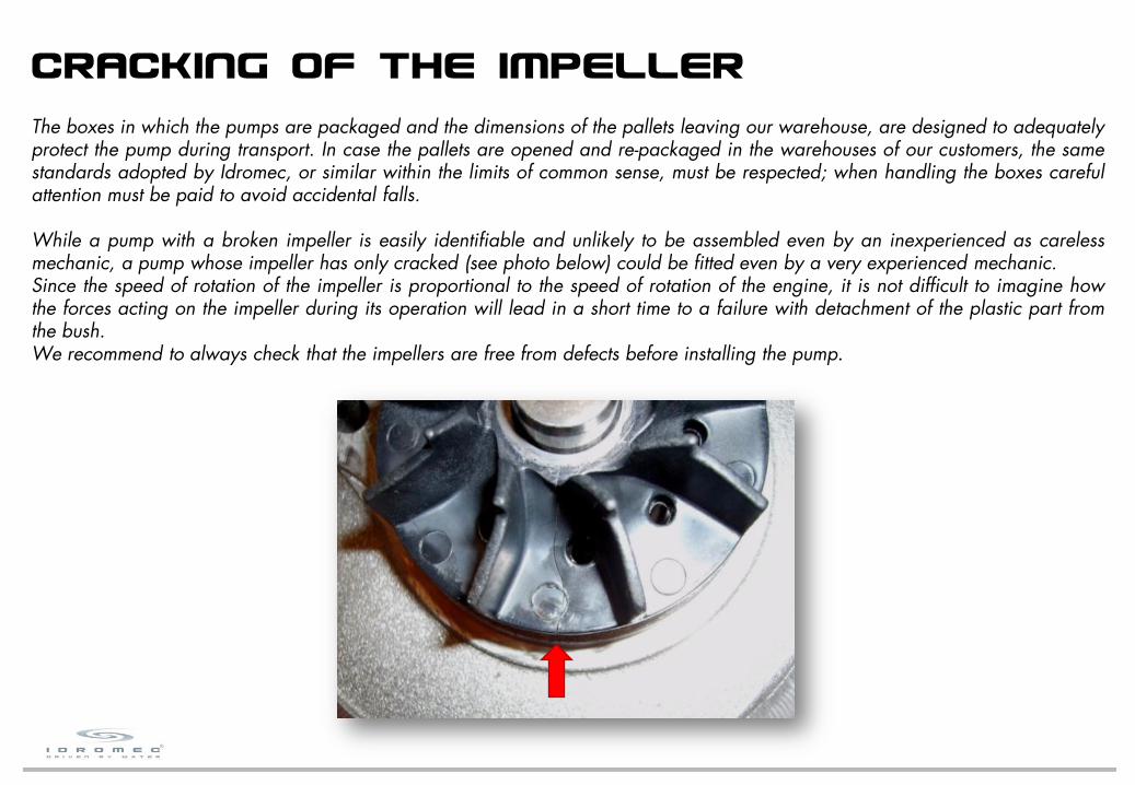
CRACKING OF THE IMPELLERThe boxes in which the pumps are packaged and the dimensions of the pallets leaving our warehouse, are designed to adequatelyprotect the pump during transport. In case the pallets are opened and re-packaged in the warehouses of our customers, the samestandards adopted by Idromec, or similar within the limits of common sense, must be respected; when handling the boxes carefulattention must be paid to avoid accidental falls.
While a pump with a broken impeller is easily identifiable and unlikely to be assembled even by an inexperienced as carelessmechanic, a pump whose impeller has only cracked (see photo below) could be fitted even by a very experienced mechanic.Since the speed of rotation of the impeller is proportional to the speed of rotation of the engine, it is not difficult to imagine howthe forces acting on the impeller during its operation will lead in a short time to a failure with detachment of the plastic part fromthe bush.We recommend to always check that the impellers are free from defects before installing the pump.
41
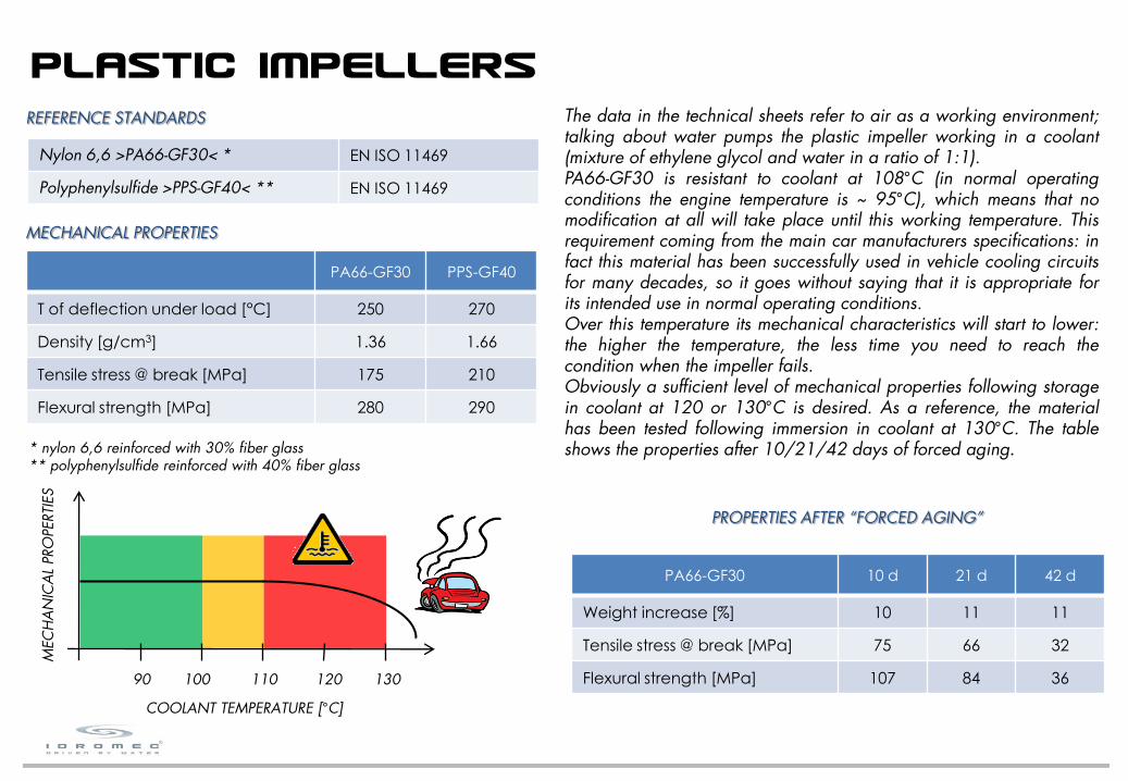
PA66-GF30 PPS-GF40
T of deflection under load [°C] 250 270
Density [g/cm3] 1.36 1.66
Tensile stress @ break [MPa] 175 210
Flexural strength [MPa] 280 290
MECHANICAL PROPERTIES
REFERENCE STANDARDS
Nylon 6,6 >PA66-GF30< * EN ISO 11469
Polyphenylsulfide >PPS-GF40< ** EN ISO 11469
* nylon 6,6 reinforced with 30% fiber glass** polyphenylsulfide reinforced with 40% fiber glass
The data in the technical sheets refer to air as a working environment;talking about water pumps the plastic impeller working in a coolant(mixture of ethylene glycol and water in a ratio of 1:1).PA66-GF30 is resistant to coolant at 108°C (in normal operatingconditions the engine temperature is ~ 95°C), which means that nomodification at all will take place until this working temperature. Thisrequirement coming from the main car manufacturers specifications: infact this material has been successfully used in vehicle cooling circuitsfor many decades, so it goes without saying that it is appropriate forits intended use in normal operating conditions.Over this temperature its mechanical characteristics will start to lower:the higher the temperature, the less time you need to reach thecondition when the impeller fails.Obviously a sufficient level of mechanical properties following storagein coolant at 120 or 130°C is desired. As a reference, the materialhas been tested following immersion in coolant at 130°C. The tableshows the properties after 10/21/42 days of forced aging.
PA66-GF30 10 d 21 d 42 d
Weight increase [%] 10 11 11
Tensile stress @ break [MPa] 75 66 32
Flexural strength [MPa] 107 84 36
PROPERTIES AFTER “FORCED AGING”
90 100 110 120 130
COOLANT TEMPERATURE [°C]
MEC
HA
NIC
AL
PRO
PERTI
ES
42
PLASTIC IMPELLERS

If the operating conditions are not the expected ones, other external factors, whichare out of any possible control, will affect the impeller life.In particular, coolant pollution (by rust, dirt, incrustations, etc.) will affect the chemicalproperties of the coolant.The coolants recommended by automotive manufacturers are not only antifreeze.They vary due to the different requirements in terms of chemical and physicalcompatibility with the various materials which make up the cooling system, whichinclude a very wide range of metals, polymers, rubbers and ceramic materials.If the chemical properties of the coolant are modified by an external factor, it mightno longer be compatible with the impeller material, which will fail after a short time.
In any case, never forget that all the vehicles produce warning signals (leaks, noise,over-heating of coolant) that should alert the driver to the malfunction; that enables torepair the fault before it produce more serious damages.
We can conclude that when the impeller breaks because of lowered mechanicalproperties, it can only be due to:
1) coolant temperature > 130°C
2) coolant temperature within 110°C and 130°C for a long time
3) coolant temperature < 110°C with inadequate coolant
In any of these cases we consider ourselves not responsible.
43
BELTTENSION
OVERLOAD
44
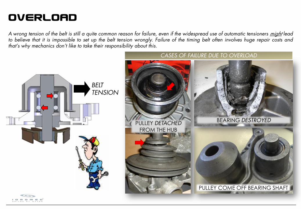
A wrong tension of the belt is still a quite common reason for failure, even if the widespread use of automatic tensioners might leadto believe that it is impossible to set up the belt tension wrongly. Failure of the timing belt often involves huge repair costs andthat’s why mechanics don’t like to take their responsibility about this.
PULLEY DETACHEDFROM THE HUB
PULLEY COME OFF BEARING SHAFT
BEARING DESTROYED
CASES OF FAILURE DUE TO OVERLOAD

F1 = BELT TENSION
AB
F2 = OUTPUT FORCE
F2 = x F1 = = 2,25 x F1A + B
A
12 + 15
12
(ex. PA45017)
45
When one of these situations happen, the bearing analysis can tell us if a condition of overload actually existed: in fact thebearing works as a second-class lever (nutcracker) where the row of balls on impeller side is the “fulcrum”, the belt tension is the“input effort” and the row of balls on pulley side generates the “output load”.
When a condition of overload exists, the rolling elements of the bearing will show signs of overheating.If the bad working condition is protracted and/or combined with other bad working conditions (for example a leaking mechanicalseal, with coolant seeping into the bearing), the rolling elements will start to degrade, showing signs of rust, pitting and corrosion.

46
AUTOMATIC TENSIONERSBelt drive systems for both timing and accessory drive can have different tensioning systems. In the past, engines used a manualtensioner (or eccentric pulley) which had to be installed and then locked in place. Over time the belt tension would change asthere is no adjustment of the tensioner after the initial installation. Nowadays, automatic tensioners are being used to maintain analmost constant belt tension.
Although the drive is equipped with an automatic tensioner, this still has to be set up correctly. If the tension is not set up correctly,the tensioner will maintain the wrong tension over time. When the vehicle is released with a wrong positioned tensioner, severeengine damage will happen sooner or later.
As many branded belt manufacturers keep saying:
just because there's an automatic tensioner doesn't mean it's working right!

WHOSE RESPONSIBILITY?When we dismantled a pump because its bearing had failed we almost always stated that the fault was not due to a sudden breakbut to a protracted bad working condition.All the vehicles produce warning signals (leaks, noise, over-heating of coolant) that should alert the driver to the malfunction; thatenables to repair the fault before it produce more serious damages.This is why, anyhow, we consider us not liable for damages that could have been avoided simply by paying attention to warningsignals.
47
NO LEAK OR NOISE DETECTED BEFORE
THE ENGINE CRASH?

IDROMEC COOLANTS
48
Given the importance of the coolant in the operation of the water pump, Idromec decided to insert among its own products arange of quality coolants free from substances toxic for health such as Nitrites, Phosphates and Borates and completelybiodegradable.Our coolants, diluted 1:1, lower the freezing point to –40°C and at the same time raise the boiling point to +110°C, protectingfrom limestone, rust and erosion.Our coolants contain proper corrosion inhibitors in the percentages indicated by car producers; however, the inhibitors guaranteethe proper protection if the dilution percentages are greater than 30% and lower than 50%.
DILUTION FREEZING POINT BOILING POINT
10% vol. -4 °C 102 °C
20% vol. -9 °C 104 °C
30% vol. -17 °C 106 °C
40% vol. -26 °C 108 °C
50% vol. -38 °C 110 °C
Our coolants, thanks to the fact that they are based on pure monoethylene glycol and thanks to the advanced formulation of theinhibitors, are highly reliable products towards metallic and non-metallic materials forming the cooling circuit: they are incompliance with the ASTM D3306 specification that establishes the requirements according to which antifreezes based onmonoethylene glycol protect from corrosion and they are in compliance with the specifications of the main car producers.
SPECIFICATION COMPLYING
Renault 41-01-001/q
VW TL 774 D (G 12)
Mercedes MB 325.3
GM US 6277 M
Ford ESE M97B49-A
SEAT
SKODA

IDROMEC COOLANTS
49
PA30090mileage: 100.000 km
QUALITY COOLANT
PA31001mileage: 10.000 km
INADEQUATE COOLANT

APPENDIX C - COMPARISONWITH COMPETITORS

Our laboratory carried out a full comparison (Idromec vs. COMPETITORS A and B) of the dimensional and performances.The analysis has been carried out following Idromec Specifications for the parts approval I7-12.02, which complies with Fiat AutoSpecifications 9.02320/01. Purpose of this Specifications is to outline the characteristics the water pumps have to meet for thevalidation of a new part approval and to identify the tools to be used for the tests and the methods to be applied for measuringthese characteristics.
51
FOREWORD
IDROMEC - PA37034
COMPETITOR A
COMPETITOR B

IDROMEC - PA37034 COMPETITOR A COMPETITOR B
Pulley side diam. = 15.008 mmImpeller side diam. = 15.008 mmOuter ring diameter = 30 mmOuter ring height = 38.9 mmINNER STRUCTURE: roller-ball
Pulley side diam. = 15.008 mmImpeller side diam. = 15.008 mmOuter ring diameter = 30 mmOuter ring height = 36 mmINNER STRUCTURE: roller-ball
Pulley side diam. = 15.918 mmImpeller side diam. = 15.918 mmOuter ring diameter = 30 mmOuter ring height = 36,5 mmINNER STRUCTURE: roller-ball
Outer diameter = 36.6 mmInner diameter = 14.9 mmCOUNTERFACE: Al2O3 - C
Outer diameter = 36.6 mmInner diameter = 14.9 mmCOUNTERFACE: Al2O3 - C
Outer diameter = 36.6 mmInner diameter = 15.9 mmCOUNTERFACE: Al2O3 - C
Outer diameter = 62 mmNumber of vanes = 9MATERIAL: PA66-GF30Weight: 27 g
Outer diameter = 62 mmNumber of vanes = 8MATERIAL: steel plateWeight: 52 g
Outer diameter = 62 mmNumber of vanes = 8MATERIAL: steel plateWeight: 49 g
Centering diameter = 50 mmThreaded holes = 3 x M8Interaxis = 68 mmMATERIAL: sintered steel
Centering diameter = 50 mmThreaded holes = 3 x M8Interaxis = 68 mmMATERIAL: sintered steel
Centering diameter = 50 mmThreaded holes = 3 x M8Interaxis = 68 mmMATERIAL: sintered steel
The main differences, highlighted in red, are:
the impeller material and weight (COMPETITOR A is 92% heavier) the number of vanes of the impeller (IDROMEC is bigger)
52

RESULT NOTES
IDROMEC OK No defects/anomalies
COMPETITOR A OK No defects/anomalies
COMPETITOR B OK No defects/anomalies
53
[* working pressure on a car is ~ 0.7 bar]
RESULT NOTES
IDROMEC OK No leak detected
COMPETITOR A OK No leak detected
COMPETITOR B OK No leak detected
VISUAL ANALYSIS
STATIC LEAK TEST AT ROOM TEMPERATURE
Specifications requirements: the pumps must be free from dents, burrs and any other defects which might jeopardize fitting andcorrect working.
Specifications requirements: fit the pump on the test bench for leak test; close all the holes (beside the drain hole) and process thepump for 30 s with an internal pressure of 1.5 bar *. No leaking (no drops) is admitted at the drain hole.

54
RESULT NOTES
IDROMEC OK No leak detected
COMPETITOR A OK No leak detected
COMPETITOR B OK No leak detected
RESULT NOTES
IDROMEC OK No leak detected
COMPETITOR A OK No leak detected
COMPETITOR B OK No leak detected
STATIC LEAK TEST AT -20°C
Specifications requirements: fit the pump on the test equipment filled with cooling liquid; put the pump inside the freeze room andset the temperature to -20 °C; process the system for 30 minutes with an internal pressure of 1.5 bar. No leaking (no drops) isadmitted at the drain-hole.
DYNAMIC LEAK TEST
Specifications requirements: fit the pump on the test bench and set the temperature to +90 °C; when the room temperature isstable close the outlet valve and process the pump for 5 minutes with an outlet pressure of 1.5 bar. No leaking (no drops) isadmitted at the drain-hole.

Picture of the test bench for performance test Control panel of the test bench for performance test
[* here: from 1000 rpm to 7000 rpm]
55
PERFORMANCE TEST
Specifications requirements: fit the pump on the test bench and, with the inlet valve fully open, set the temperature to +25 °C; atvarious values ni of the speed of rotation*, detect the curve head H / flow rate Q.Carry out the same test in the same conditions on the OE sample and compare the curves: the values detected on the sampleunder test must be within ± 7% of the ones detected on the OE sample.

IDROMEC, COMPETITOR A and COMPETITOR B pumps are within the acceptance limit.
56
RESULT NOTES
IDROMEC OK +3 % compared to OE
COMPETITOR A OK +0 % compared to OE
COMPETITOR B OK -1 % compared to OE

IDROMEC - PA37034 COMPETITOR A
57
COMPETITOR B
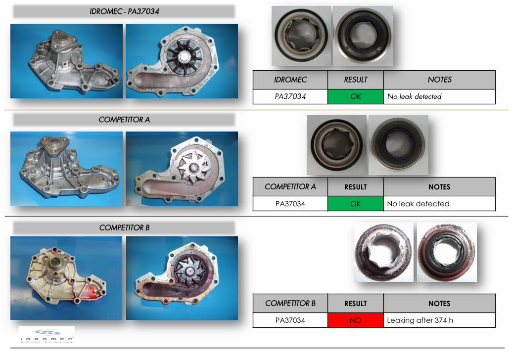
LIFE TEST
Specifications requirements: fit the pump on the test bench and set the temperature to +90 °C. Process the pump at 6000 rpm for500 h under a load of 50 daN.During the test the pump should not give rise to any incidents.
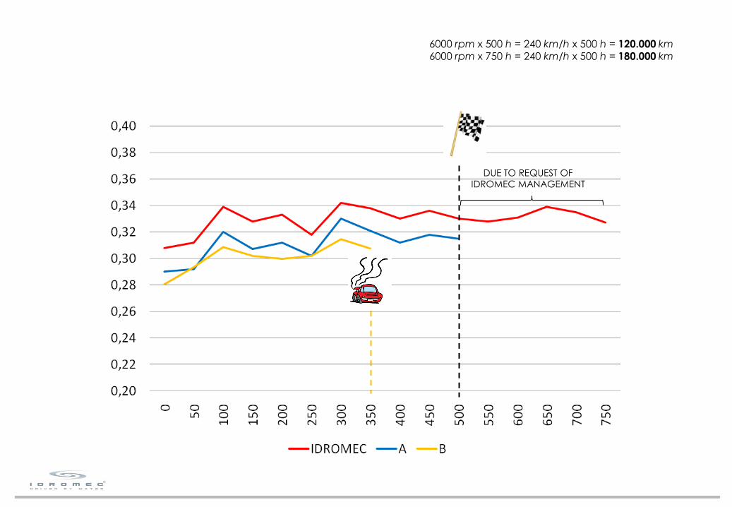
6000 rpm x 500 h = 240 km/h x 500 h = 120.000 km6000 rpm x 750 h = 240 km/h x 500 h = 180.000 km
58
DUE TO REQUEST OFIDROMEC MANAGEMENT
IDROMEC - PA37034
COMPETITOR A
IDROMEC RESULT NOTES
PA37034 OK No leak detected
COMPETITOR A RESULT NOTES
PA37034 OK No leak detected
59
COMPETITOR B RESULT NOTES
PA37034 NO Leaking after 374 h
COMPETITOR B

IDROMEC - PA37034
NOISE: 46 dBWAVE FORM: normal
COMPETITOR A
NOISE: 45 dBWAVE FORM: normal
INNER STRUCTURE:6 balls ø6.3459 rollers ø4.80x11.8HARDNESS:shaft - 61.0 HRCraceway - 62.5 HRCballs - 61.0 HRCrollers - 61.5 HRC
INNER STRUCTURE:6 balls ø6.3459 rollers ø5.00x8.0HARDNESS:shaft - 61.5 HRCraceway - 63.0 HRCballs - 61.0 HRCrollers - 61.0 HRC
60
INNER STRUCTURE:6 balls ø6.34510 rollers ø4.50x8.0OVERHEATING
COMPETITOR B
NOISE: 61 Db WAVE FORM: irregular
61
The dimensional results brought to light no differences about dimensions that we regard as critic.
The material results brought to light no differences at all in the body, bearing, mechanical seal and flange materials.
For the impeller IDROMEC uses PPS-GF40, while COMPETITORS A and B uses steel plate.
BRASS AND STEEL PLATE IMPELLERS ARE THE PAST, PA66-GF30 AND PPS-GF40 ARE THE FUTURE
In fact almost all the car manufactures require PA66-GF30 and PPS-GF40 impellers for the OES water pumps.
The functional tests results brought to light
no differences between IDROMEC and COMPETITOR A important differences between IDROMEC and COMPETITOR B, in fact:
COMPETITOR B’s pump began to leak after 374 h , the bearing was noisy and showed signs of overheating which means that itwas going to fail
IDROMEC pump began to leak after 780 h , the bearing was still working correctly.
GENERAL CONCLUSIONS