The principal axes are directions along which the starting vector and
58
-
Upload
tashya-palmer -
Category
Documents
-
view
30 -
download
0
description
This is the trace of the strain tensor. In general the trace of the strain tensor gives area change in 2-D and volume change in 3-D. The principal axes are directions along which the starting vector and ending vector are parallel. Pure shear = principal axes do not rotate with time. - PowerPoint PPT Presentation
Transcript of The principal axes are directions along which the starting vector and


€
εij =εxx εxy
εyx εyy
⎡
⎣ ⎢
⎤
⎦ ⎥=
−0.1 0
0 0.2
⎡
⎣ ⎢
⎤
⎦ ⎥
(10,10)
(9,12)
(10,0)(9,0)
y
X
(0,10)
(0,11)

This is the trace of the strain tensor. In general the trace of the strain tensor gives area change in 2-D and volume change in 3-D
€
εxx +ε yy = −0.1+ 0.2 = 0.1
The principal axes are directions along which the starting vector and ending vector are parallel
Pure shear = principal axes do not rotate with time

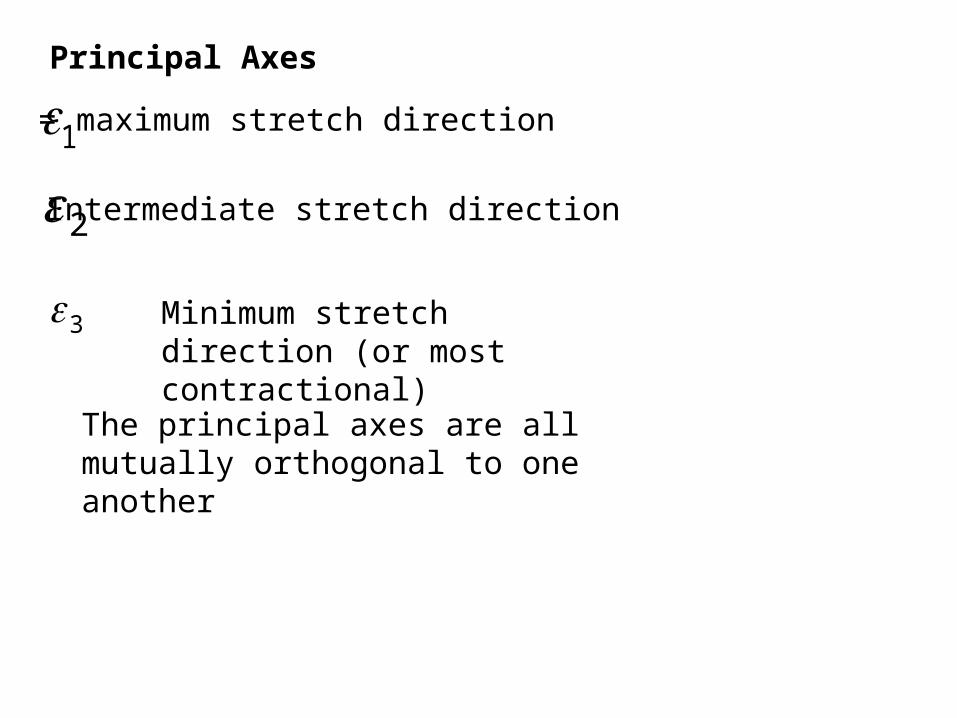
Principal Axes
€
ε1 = maximum stretch direction
Intermediate stretch direction
€
ε2
€
ε3 Minimum stretch direction (or most contractional)
The principal axes are all mutually orthogonal to one another

€
εij =εxx εxy
εyx εyy
⎡
⎣ ⎢
⎤
⎦ ⎥=
0.1 0.1
0.1 0.1
⎡
⎣ ⎢
⎤
⎦ ⎥
€
Δx = 0.1x + 0.1y
€
Δy = 0.1x + 0.1y
(10 ,0)becomes (11,1)
(10,-10) remains fixed, as does (-10, 10)
(0, 10) becomes (1,11)
(10,10) becomes (12,12) etc...

(12,12)
(10,0)
(11,1)
y
X
(10,10)
(0,10)
(1,11)
€
εij =εxx εxy
εyx εyy
⎡
⎣ ⎢
⎤
⎦ ⎥=
0.2 0.0
0.0 0.0
⎡
⎣ ⎢
⎤
⎦ ⎥
In principal axis coordinate system this tensor can be written:

Simple Shear
• In Simple shear the principal axes rotate with increasing shear
• Simple shear applies only to finite strain

MarkerThis part of marker
not disformed
Rotational strain


Stress = Force/Area
Force is measured in units of mass*acceleration
1 N (Newton) = 1 kg * m * s-2
another common unit for force is the pound


Pressure is a number. It corresponds to a special kind of stress.
Stress is a tensor, but it has the same units as pressure (Pa)
1000 Pa = 1 kPa1,000,000 Pa = 1 MPa (about 10 bars)

Traction is a Vector
• Tractions are vectors = force/area
• Traction can be resolved into two components
Normal component to plane = normal stress
Tangential component = shear stress


The stress tensor
• The stress tensor is symmetric
• The stress tensor has 3 principal axes
• The principal axes are mutually orthogonal
• principal axis = direction in which the traction vector is parallel to normal to plane => no shear stress resolved on that plane

€
σ 2
€
σ1
€
σ 3
= maximum compressive principal stress
= intermediate compressive principal stress
= minimum compressive principal stress

Normal Stress and Shear Stress
€
σn = Normal Stress resolved on plane
€
τ = shear stress resolved on plane


Anderson Faulting Theory
• If σ1 is vertical then a new fault will be a normal fault (extensional)
• If σ1 is horizontal and σ3 is vertical then reverse (thrust) fault (contractional faulting)
• If σ1 and σ3 are both horizontal then strike-slip (transcurrent) fault

Fault Angles and Principal Stresses
σ2 in the plane of the fault
σ1 20°-40° from the plane of the fault
σ3 50°-70° from the plane of the fault

σ1
σ1
σ3
σ3
θ
θ
σn = (σ1+σ3)/2 - [(σ1-σ3)/2] cos 2
τ = [(σ1-σ3)/2] sin 2
THESE ARE ALSO THE EQUATIONS FOR A CIRCLE WITH A RADIUS OF (σ1-σ3)/2AND A CENTER (σ1+σ3)/2 TO THE RIGHT OF WHERE THE AXES CROSS!!!!

τ
σn
φ = atan μfrictional yield envelope
frictional yield envelope

τ
σnσ
1
σ3
σ1
σ3
2θ
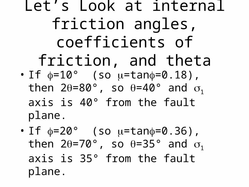
Let’s Look at internal friction angles, coefficients of friction,
and theta
• If =10° (so =tan=0.18), then 2=80°, so =40° and σ1 axis is 40° from the fault plane.
• If =20° (so =tan=0.36), then 2=70°, so =35° and σ1 axis is 35° from the fault plane.

• If =30° (so =tan=0.58), then 2=60°, so =30° and σ1 axis is 30° from the fault plane.
• If =40° (so =tan=0.84), then 2=50°, so =25° and σ1 axis is 25° from the fault plane.
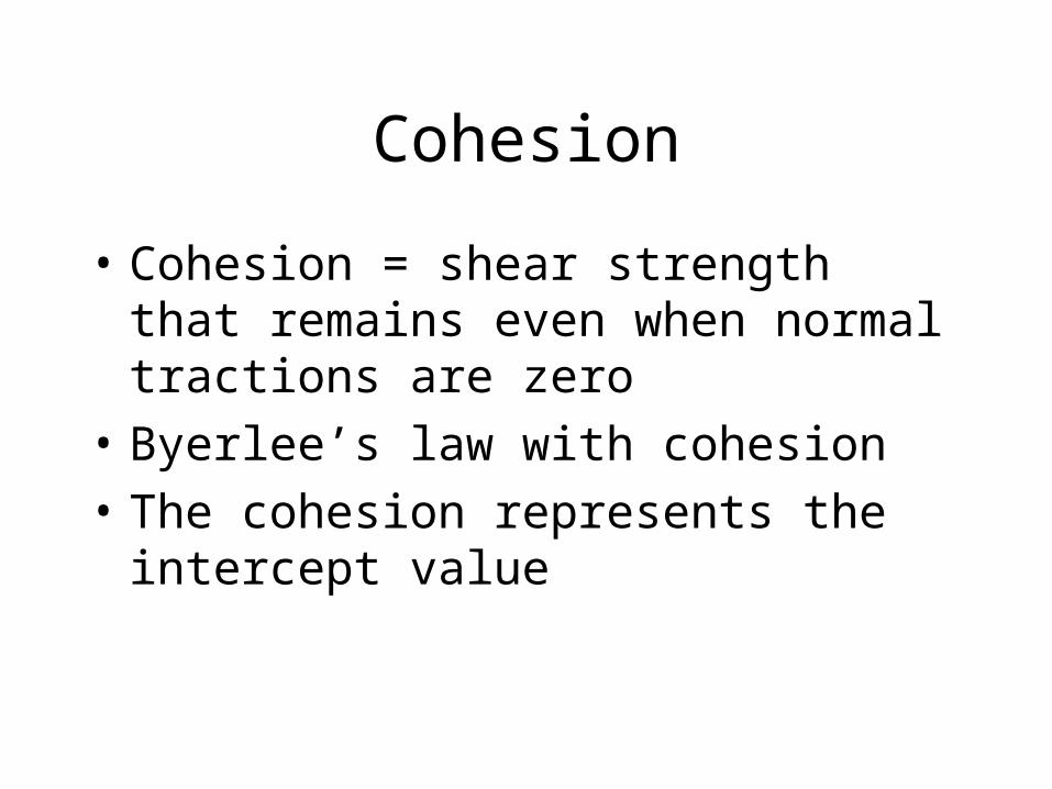
Cohesion
• Cohesion = shear strength that remains even when normal tractions are zero
• Byerlee’s law with cohesion
• The cohesion represents the intercept value


Pre-existing faults
• If there are pre-existing faults, then figure in previous slide predicts a range of orientations of faults, with respect to maximum principal stress direction that can slip
• If there are no pre-existing faults, then only one orientation is possible


Role of Fluid Pressure or Pore Pressure
• Hydrostatic Pressure: Phydrostatic = water g z
• Lithostatic pressure is when entire weight of the overlying rock (density rock) is being supported
• Plithostatic = rock g z

Fluid Pressures and Tractions
• Fluid Pressures can support normal tractions but not shear tractions!
• Elevated fluid pressures make the Mohr circle move to the left

Effective Stress
• Effective Stress = total stress minus the fluid Pressure
σ1' = σ1 - Pf
σ2' = σ2 - Pf
σ3' = σ3 - Pf
• Shear Tractions are not affected!

σ
τ
σnσ
1
σ3
1
σ3
Pf

τ
σn
tensile crack or joint (with
a single orientation normal
to minimum stress axis)
conjugate tensile
fractures (joints)
conjugate faulting


Joints
• The


![[means: CONOMy - Meidell · [Axes] - Linear guides in X, Y and Z directions - Linear scales in X directions ... and two motors in a master-slave configuration. y-axis: The Y-axis](https://static.fdocuments.net/doc/165x107/5e8556529c5dfb2e72091d78/means-conomy-meidell-axes-linear-guides-in-x-y-and-z-directions-linear.jpg)

![[means: CONOMy[Axes] - Linear guides in X, Y and Z directions - Linear scales in X directions ... and two motors in a master-slave configuration. y-axis: The Y-axis has a ram configuration.](https://static.fdocuments.net/doc/165x107/5e8556519c5dfb2e72091d76/means-conomy-axes-linear-guides-in-x-y-and-z-directions-linear-scales-in.jpg)