The Presentation Design of WSDM - Vrije Universiteit Brussel · The Presentation Design of WSDM...
77
Vrije Universiteit Brussel Faculty of Science Department of Computer Sciences The Presentation Design of WSDM Michiel Piessens Academic Year 2003-2004 Essay brought forward to achieve the degree of Licentiate in the Applied Computer Sciences Promotor: Prof. Dr. Olga De Troyer 1
Transcript of The Presentation Design of WSDM - Vrije Universiteit Brussel · The Presentation Design of WSDM...

Vrije Universiteit BrusselFaculty of Science
Department of Computer Sciences
The Presentation Design of WSDM
Michiel PiessensAcademic Year 2003-2004
Essay brought forward to achieve the degree of Licentiate in the Applied Computer Sciences
Promotor: Prof. Dr. Olga De Troyer
1

Vrije Universiteit BrusselFaculteit WetenschappenDepartement Informatica
De Presentatie ontwerpfase van WSDM
Michiel PiessensAcademic Year2003-2004
Verhandeling voorgedragen tot het behalen van de graad van Licentiaat in de Toegepaste Informatica
Promotor: Prof. Dr. Olga De Troyer
2

Abstract
WSDM, or Web Site Design Method (pronounced “WiSDoM”) is an approach for designing websites, developed at WISE. Rather than taking an organization's data or database as starting point andwondering how all of that should be displayed on the Internet (the so-called data-driven approach),WSDM takes as starting point the needs and requirements of the intended audience(s) of the website.
In WSDM 5 different phases are distinguished: mission statement, audience modeling, conceptualmodeling, implementation design and implementation.
In this thesis, the presentation design, part of the implementation design phase of WSDM, iselaborated. The purpose of this thesis is to suggest, and to specify in detail, how presentation designcan be done in the context of WSDM.
Therefore, after discussing some relevant hypermedia application design methods, a completepresentation design method is proposed, containing the definition of concepts needed to design thepresentation layer at a conceptual level, a notation that can be used to express those concepts and aa guide that leads the developper/designer through a number of different steps that are involved inthe presentation design of WSDM.
3

Samenvatting
WSDM, ofwel Web Site Design Method (uitgesproken als WiSDoM), is een benadering –ontwikkeld op WISE – voor het ontwerpen van web sites. In plaats van de data of database van eenorganisatie als startpunt te gebruiken en zich af te vragen hoe dat allemaal kan afgebeeld worden ophet Internet (de zogenaamde data-gestuurde benadering), neemt WSDM de behoeften enrequirements van de vooropgestelde doelpublieken van de website als startpunt.
In WSDM worden 5 verschillende fasen onderscheiden: bepalen van de 'mission statement', hetmodeleren van de doelpublieken, bouwen van een conceptueel informatie-, functioneel- en navigatiemodel, conceptueel uitwerken van de implementatie en het implementeren zelf.
In deze thesis wordt de presentatie ontwerpfase, zelf deel van de uitwerking van de implementatie-ontwerpfase, uitgewerkt. De doelstelling van deze thesis is het suggereren, en het in detailspecifiëren, hoe het ontwerpen van de presentatie kan gebeuren in de context van WSDM.
Daarom wordt er, na het bespreken van een aantal relevante hypermedia ontwerpmethoden, eenvolledige presentatie ontwerpmethode voorgesteld die onder andere bevat: de definitie van deconcepten die nodig zijn voor het conceptuele ontwerp van de presentatie-laag van een toepassing,een notatie om die concepten te representeren en een leidraad die de gebruiker gidst doorheen eenaantal verschillende steppen met betrekking tot het ontwerpen van de presentatie in WSDM.
4

Acknowledgements
Four years ago I would never have thought that I should ever be finishing a thesis. At the time then,it seemed impossible to reach that goal, ever.And now it's done. With this thesis I can end a period in which it was quite an adventure to combinea full-time job, house, wife and children with a study at the university.
This thesis is the endpoint of a period and I couldn't have done this all during the past four yearswithout the support and help a lot of people.
My special thanks go to:
Els Ockerman, my wife, without whose love, support and patience I would never have finished thiswork.
Our sons and daughter, Jarne, Matthis, Hannes and Nienke, for their love and understanding for somuch time I spent in front of the computer over the last few years.
Our parents, brothers and sisters who were there when we needed someone to help. To all of them:thanks for being there and for all the big and little things you've done for us in the past four years.
I would also like to give some words of gratitude to my colleages at work, who were always readyto take over my work when I wasn't available because of lessons, projects, meetings, exams at theuniversity or sleepless nights. Special thanks to Frans Meert and Peter Fontaine, who allowed me tospend some time at work for finishing university related projects.
And at last I would like to thank Prof. De Troyer for allowing and helping me to make a thesis in aresearchfield that is quite interesting and highly evolving. With this thesis, I have the feeling ofhaving created something useful, and that's important to me.
5

Contents
Abstract.................................................................................................................................................3Samenvatting........................................................................................................................................4Acknowledgements..............................................................................................................................5Contents ...............................................................................................................................................6Chapter 1 - Context..............................................................................................................................7Chapter 2 – Existing Related Hypermedia design Methods ..............................................................11
2.1. UWE.......................................................................................................................................122.2. WEBML..................................................................................................................................142.3. OO-H......................................................................................................................................172.4. OOHDM.................................................................................................................................222.5. Conclusion..............................................................................................................................27
Chapter 3 – The Presentation Design of WSDM...............................................................................293.1. Introduction.............................................................................................................................293.2. Presentation Design ...............................................................................................................303.3. Presentation Design in WSDM – Concepts and Notation......................................................32
3.3.1. The Abstract User Interface model concepts .................................................................333.3.2. The Transformation Model Concepts.............................................................................383.3.3. The Synchronization Model Concepts............................................................................40
3.4. Presentation Modeling Language Description .......................................................................443.4.1. Presentation Design Language........................................................................................443.4.2. Catalog of Modeling Elements .......................................................................................45
3.4.2.1. User Interaction Elements.......................................................................................453.4.2.2. Static Elements........................................................................................................473.4.2.3. Multimedia and external application elements........................................................483.4.2.4. Composites..............................................................................................................50
3.5. WSDM Presentation Design Guide.......................................................................................53Step 1 – Determine site-global user-interface rules and constraints.........................................54Step 2 – Determine the different pages to be built per audience class......................................58Step 3 – Modeling of global reachable Pages..........................................................................62Step 4 – Modeling of global site menu and context menus......................................................65Step 5 – Modeling of reusable User Interface components......................................................68Step 6 – Modeling of the Pages per audience track..................................................................69Step 7 – Create the Transition model........................................................................................73Step 8 – Create the Synchronization model..............................................................................74
Conclusion..........................................................................................................................................75References .........................................................................................................................................76
6

Chapter 1 - Context
Short introduction to WSDM
In this chapter a short description of WSDM (pronounced as “Wisdom”) is given in order to providean overview of the different phases of the design method, together with some explanation of theterminology used in the method.For more background information about the WSDM design method, I refer to [1].
After reading this section, it should be clear what the context of the presentation design phase is.
When starting with WSDM, it is important to know that it is a user-centered, audience-driven website design method – in contrast with data-driven or impementation oriented methods. This meansthat in early stages of the design, the different types of audiences are identified, together with theircharacteristics and information requirements.
In WSDM, the design of a website passes through a number of phases as shown in fig. 1.1. [2](presentation):
Fig 1.1 – Design Phases of WSDM
The goal of each phase is to produce a certain outcome which can be used as input in the next stepsof the method. In the first phase, the mission statement is determined. The mission statement should express thepurpose and subject of the website, as well as declaring the target audience(s).
7
Conceptual Design
Mission statementSpecification
Audience Modeling
AudienceClassification
Audience ClassCharacterization
NavigationalDesign
FunctionalModeling
InformationModeling
Implementation design
PageDesign
PresentationDesign
DataDesign
Implementation

After this phase the Audience Modeling takes place. During the Audience Modeling phase, thedifferent types of users of the target audience(s) are classified in so-called Audience Classes.An Audience Class describes users which have similar information- and functional requirements. The outcome of this phase is an Audience Class Hierarchy and an Audience Class Description foreach identified Audience Class. Each Audience Class Description contains Informational,Functional and Usability Requirements of the described Audience Class – Fig 1.2.
Fig 1.2 – Result of Audience Modeling phase
The Audience Class information requirements contain a description of the information that thespecified audience class is expected to find on the website.
The Functional Requirements contain a description of the functionality that a given Audience classis expecting in the website.
The Usability Requirements of an Audience Class contain a description of the different usabilityaspects with respect to the given Audience Class (e.g. Language requirements, navigationalrequirements, etc.)
And finally, for each Audience Class a set of Characteristics is specified (e.g. Language, computerexperience, ...).
With respect to the subject of this paper, it is important to keep the different Audience classes inmind because they will act as a guide for the Presentation Design of the website.
The third phase is the Conceptual Design of the website. Please take note that this phase cannot bestarted before the Audience Modeling has been finished. The Conceptual Design phase is split into three parts: Information Modeling, Functional Modelingand Navigation Design.
During the Information Modeling, a Task analysis is performed for each Functional Requirement ofevery Audience Class. During the elaboration of each task and subtasks, an Object Chunk is createdthat describes the information that is needed during the execution of the Task. When the Information Modeling of all Tasks is finished, all generated Object Chunks are combinedinto a Business Information Model. The Business Information Model can than be used to generate adatabase schema.
8
Audience Class Description• Requirements:
InformationFunctionalUsability
• Characteristics
Audience Class Description• Requirements:
InformationFunctionalUsability
• Characteristics
Audience Class HierarchyAudience Class Hierarchy

In short: after performing the Informational and Functional Modeling, a set of Tasks and SubTasksis generated. For each (Sub-)Task, an Object Chunk is provided and the Business InformationModel is available.
The next step of the Conceptual Design Phase is the Navigational Design. This happens in 5 steps [2]
�� Make task model for each task using components and process logic links�� Make audience track for each audience class by compose task models of an audience class using
structural links�� Compose audience tracks into conceptual structural model using structural links following the
audience class hierarchy �� Make audience chunk model�� Add navigational aid links if necessary
A Task Model describes the different steps in a task and the sequence in which the steps can beperformed.
With respect to the Presentation Design, it is imporant to have completed the Conceptual DesignPhase because of the rich and useful information that is produced during the Informational,Functional en Navigational Modeling. The generated Task models and the conceptual structural model will be used as the primary guideduring the Presentation Design Phase.
9
Submit Paper
Info & File
Add Co-Author
RegisterNewPaper
Submit New Paper
Submit Paper
Info & File
Add Co-Author
RegisterNewPaper
Submit New Paper
Visitor PC-Chair
Author
Reviewe
PC-Member
Visitor PC-Chair
Author
Reviewe
PC-Member

Now that the Conceptual Design is finished, the Implementation Design can begin.
This phase too splits in three subphases:�� Page Design� Groups information in pages, following the Navigation Design).
�� Presentation DesignSpecifies the look and feel�� Data Design� Design of databases, an XML DTD or schema, RDF Definitions
After the completion of the Implementation Design Phase, the last phase can begin: the acutalimplementation.
The subject of this paper – The Presentation Design of WSDM – will be the elaboration of thePresentation Design subphase of the Impementation Design phase.
Just as with the other phases during the website design, the Presentation Design phase too will usethe output of previous phases as its guiding input, especially the Task models and the conceptualstructural model will provide useful.
In the next chapter, another four hypermedia application design methods will be presented from theviewpoint of presentation design.
In chapter 3, the elaboration of the of Presentation Design for WSDM will be presented.
10

Chapter 2 – Existing Related Hypermedia design Methods
Before proceeding to the definition of Presentation Design and the proposition of a PresentationDesign Language and process, a few existing hypermedia application design methods in which theproblem of Presentation Modeling has been tackled, will be presented. Among the methodsavailable, only a few are selected just to show the different approaches that are used to model userinterfaces for websites or other hypermedia applications.
After summarizing each method, a short review about the presentation design phase of each methodwill be made. In this review, a number of aspects that are of interest during presentation design, areevaluated. Among these aspects are:
� The visual aspect of the models: does the user get a very clear idea about the staticstructure (layout) and interactions of each presentation model element.?
� The intuitive character of the method: what knowledge is required before someone canuse the method/language?
� User/Audience driven aspect: are the userclasses or target audiences explictely taken intoaccount when building the presentation models?
� Tool support aspect: is a tool available for building the presentation design?� Codegeneration aspect: does the method support code generation – and eventually site-
generation?� Developer guidance aspect: does the method provide guidance to the developer when (s)
he is building the presentation models?
The methods under consideration are: UWE, WebML, OO-H and OOHDM.
11

2.1. UWE
UWE, UML based Web Engineering - described in [4][5][6][7] - is an object-oriented, iterativeand incremental approach based on the Unified Modeling Language (UML).
The UWE design method is centered around three main aspects of hypermedia systems. These arethe content, the navigational structure and the presentation.
Fig. 2.1. – Overview of the UWE Method.
As can be seen from figure 2.1. , the modeling activities are conceptual modeling, navigation andpresentation design. The method uses several iterations to complete the design.
Conceptual ModelingUWE, because of adhering to the UML standard, uses use cases for capturing the requirements. When building the conceptual model, the functional requirements captured with the use cases aretaken into account. The resulting artifact is a UML class model of the problem domain.
Navigation Design During the navigation design phase two models are built: the Navigation Space Model and theNavigational Structure Model.
The Navigation Space Model specifies which classes of the conceptual model can be visitedthrough navigation in the hypermedia application – in casu a Web application. This model is builtwith a set of navigational classes and associations, which are obtained from the conceptual model.
The Navigation Structure Model defines the navigation structure of the application, i.e. hownavigational objects are visited. The Navigation Structure Model contains the navigation pathstogether with additional access elements, including: indexes, guided tours, queries and menus.
12
Phases ConceptualModeling NavigationalDesign
PresentationDesign
ConceptualModelNavigationSpaceModel
andNavigationalStructureModel
PresentationModelArtifacts
Expressedusing UML Use Cases and
Class Diagram UML Class Diagram UML Prof ile (Extension)for HypermediaDesign

OCL Constraints are used to express the relationship between conceptual classes and navigationclasses or attributes of navigation classes.
Presentation Design The presentation modeling describes how the information within the navigation space and theaccess structures (menus, indexes, ...) will be presented to the user.Therefore, an abstract interface design – similar to a user interface sketch – is constructed, focusingon the structural organization of the presentation and not on the physical appearance in terms ofspecial formats, colors, etc. (these are part of the implementation phase following these modelingphases).The artifacts produced during the Presentation Design phase contain both models that describe thestatic location of the objects visible to the user, and models that describe the dynamic behaviour ofthe user interface objects in the static presentational model in response to external user events likemouse movents, mouse clicks, keyboard presses, as well as responses to internal events liketimeouts and (de-)activations.
Fig. 2.2. – example of a static presentation model for an Employee (taken from Uml2000.pdf)
Review
The Presentation Design of UWE scores very good on the visual aspect of the models: the user getsa clear idea about the layout – structural organization of the visible objects – and by using UMLstate charts, the dynamic behaviour of the objects can be specified unambigously.Because of the use of UML and a well defined notation of the concepts used, the user of the methodonly has to have a basic understanding of UML (class diagrams, stereotypes and state diagrams).The method for designing the presentation models is only implicitely user/audience driven – thenavigation space model is derived from the conceptual model which is based on the functionalrequirements captured in the use cases. The method doesn't specify that a specific presentationmodel should be constructed for each audience class.Concerning the possibility of code-generation the method provides some mechanisms – based onthe transformation of UML models into code. A tool is available to support the method: OpenUWE(see: http://www.pst.informatik.uni-muenchen.de/projekte/openuwe/). During all steps of the design process, the method provides clear guidance for the developer.
To be remembered� simple, easy to learn and extensible static presentation modeling language� standards (UML) based� support for dynamic behaviour
13

2.2. WEBML
WebML (Web Modeling Language) [8][9] consists of a notation for specifying complex web sitesat the conceptual level and a design process. WebML provides a graphical notation and an XML-based syntax for each artifact produced during the different phases of the development process. Thetextual XML representation allows code generation for automatically producing the implementationof a website.
As shown in figure 2.3. the WebML design process consists of seven phases. Iteration over eachphase is used in order to elaborate the required models.
Fig. 2.3. – Overview of the WebML Design Process and artifacts
The specification of a website in WebML consists of four orthogonal perspectives: � the structural model� the hypertext model, consisting of the Navigation Model and Composition Model� the presentation model� the personalization model
Structural Model The structure model defines or expresses the content of the website in terms of relevant entities ofreleationships. It therefore uses classical notations such as the E/R model, the ODMG object-oriented model or UML class diagrams for data modeling. Derived information is expressed using asimplified OQL-like query language.
Hypertext ModelThe Hypertext Model describes one or more hypertexts that can be published in the site. Eachhypertext defines a so-called site view. A site view in turn consists of two sub-models;
� the composition model� the navigation model
14
Phases
Artifacts
Expressed By
- Site objectives- TargetAudiences- Style Guidelines- RequiredPersonalization
- OtherconstraintsTargetAudiences
RequirementsCollection
Data DesignHypertext
Design- coarseHypertext
Design- RefinePresentation
DesignUser & Group
DesignCustomization
Design
StructuralModel
- SkeletonSite View- CoarseNavigationModel
- CoarseCompositionModel
- ElaboratedNavigationModel- ElaboratedCompositionModel
PresentationModel
- Featuresof Userprof iles
- Dif ferentSitefor each Group
PersonalizationModel
Text
E/RdiagramODMGNotation
UML Class DiagramWebML- XML
WebMLGraphicalLanguage
WebML- XML
WebMLGraphicalLanguage
WebML- XML
AbstractXMLsyntax
StyleSheets(XSL)
Specialtype ofentities in Structural
Model(prof ile= collection
of properties)
WebML- XMLSyntax

The Composition Model specifies the pages build from the hypertext and the content units within apage. There are six types of content units defined in WebML:
� data units (used to publish the information of a single object)� multi-data unit � index unit � filter unit � scroller unit � direct unit.
Each type of unit has his own WebML graphic notation.
The navigational model defines how pages and content units are linked together to form thehypertext. Two types of links are used: non-contextual links (which connect semanticallyindependent pages) and contextual links (when the content of the destination unit of the linkdepends on the content of the source unit).
Presentation Model Presentation modeling is concerned with the actual look and feel of the pages identified bycomposition modeling. The Presentation model expresses the layout and graphic appearance ofpages, independently of the output device and of the rendition language. It does so by using astylesheet in a so-called abstract XML-syntax. Presentation information can be page-specific or generic.Page-specific specifications define the presentation of a specific page, including explicit referencesto page-content. Generic specifications are based on predefined models that are independent of the specific page andinclude references to generic control elements.
Personalization Model This part defines a model of the users and user groups, specified in terms of predefined entitiescalled User and Group, which in turn are described using profiles (= a collection of attributes).
Review
The WebML method for designing web sites combines its own graphic notation with a textual XMLrepresentation for modeling. The graphic notation used for representing the hypertext models andthe composition models is quite clear and has an unambiguous character. The representation inXML is – although clear and probably more detailed – less readable and doesn't give the sameimpression as the graphical representation. In the case of the presentation design, the WebML method doesn't provide its own graphic notationbut allows the developer to choose a graphic notation with which he is accustomed. Since thepresentation design is based on the navigational and composition models – with an XMLrepresentation, it is quite common to use XSL stylesheets to transform the composition models intoa concrete implementation. WebML doesn't provide a tool for hacking XSL stylesheets. Although the dynamic behaviour of the web application is partly covered by the navigation design,it is regrettable that WebML doesn't provide a separate way for modeling the dynamic behaviour ofconceptual components within or between pages. In order to be able to use the WebML method, it is necessary to get accustomed to the WebMLgraphical notation and semantics, and have some knowledge of XML and XSL. As far as concerns the User/Audience driven aspect of the method, WebML scores quite good:during the requirements gathering phase, the target audience is determined and during later phasesthe Users and/or Groups are explicitely taken into consideration in order to created User/Group
15

customized pages and units.Tool support (commercial) is available for the WebML design process with use of the WebMLgraphic notation. Using these tools, a concrete implementation for a specific device - e.g. Web-browser, wap-device, ... - can be automatically generated.Although the method is nicely split up in a number of distinct phases (Data design, Hypertextdesign, Presentation Design, Customization design, it only provides basic guidance to thedeveloper; leaving a lot of freedom to the designer/developper)).
To be remembered:� user interfaces are defined by applying stylesheets on conceptual models� explicit customization design (personalization design) for Users and/or Groups
16

2.3. OO-H
OO-H, the Object-Oriented Hypermedia method, see [10][11][12][13], extends traditional softwareengineering approaches based on UML with two new diagrams: navigation access diagrams (NAD)and abstract presentation diagrams (APD).
Fig. 2.4. – Overview of the OO-H Method and artifacts
The OO-H method defines five phases – see figure 2.4. – which starts with functional requirementsgathering and results in a concrete Web interface.
The first to phases, the gathering of functional requirements and the construction of the BusinessClass Diagram, are common to other UML-based design methods.During the first phase, UML use cases are used to capture the system functional requirements foreach user type (actor). It is important to note that the use cases represented in OO-H are businessuse cases, and so they may have different implementations depending on the target technology,architecture and target platform.OO-H uses these use case diagrams as a basis on which the navigation requirements are structured.
Together with the use case diagrams, OO-H also needs a UML Business Class Diagram (as a resultof the second phase) as the input to the process for constructing the Navigation Access Diagrams.
In the third phase, the Navigation Modeling, the Navigation Access Diagram (NAD) is build.The construction process of the NAD's is done using the following steps [13]:
�� Grouping process on the use-case diagrams: create navigation targets by packaginguse-cases following a set of criteria (semantic, functional dependency and datacriteria).
�� Automatic derivation of the top level of the NAD diagram �� Construction of the different NAD diagrams, driving the navigation decisions by the
corresponding storyboard.
The navigation model is caputered by means of one or more NADs; the designer should construct asmany NADs as different views of the system are required and should provide at least a different
17
Phase
Artifacts
ExpressedUsing
GatheringFunctional
Requirements
BuildingBusiness
Class Diagrams
NavigationModeling PresentationModeling
CodeGeneration
FunctionalRequirementsDescription
BusinessClassModel NavigationModel PresentationModel GeneratedWeb
Interface
UML Use Cases UML Class Diagrams
NavigationAccessDiagram(NAD) - an
OO-H enhancedUML Class diagram
APD's en CLD's(w hichare XML
documents)ASP,PHP, JSP, ...

NAD for each identified user profile.
Navigation Access Diagrams are based on four constructs:� Navigation Classes. These are enriched domain classes with attribute and method visibility that
has been restricted according to the users access permissions and navigation requirements of theuser.
� Navigation Targets. These group the elements of the model that collaborate in the coverage ofeach user navigation requirements.
� Navigation Links. These define the navigation paths the user is able to follow through thesystem. They may have a navigation pattern and a set of navigation filters (expressed using OCL)associated. Six link types are defined.� Internal Links (I-Links), which define the navigation path inside the boundaries of a given
Navigation Target.� Traversal Links (T-Links) which define the navigation between navigation classes belonging
to different Navigation targets.� Requirement Links (R-Links) which define a starting navigation point in each Navigation
Target. � Exit Links (X-Links) which point at places outside the boundaries of the application.� Service Links (S-Links) and Response Links (R-Links) that show services available to the
user type associated with that NAD and the view the user accesses when the interface recoversthe control of the application. S-Links also gather the way the user is required to introduce theparameters needed for the invocation of any method.
� Collections are (possibly) hierarchical structures defined on Navigation Classes or NavigationTargets. They provide the user with new ways of accessing the available information.
After constructing the NAD, all the information needed to automatically generate a functionalprototype is available, but OO-H recognizes the need for a greater level of interface sophisticationregarding appearance and usability features.It therefore introduces the Abstract Presentation Diagram (APD) and the Composite LayoutDiagram (CLD) which define a set of mechanisms to refine the interface at a lower level ofabstraction.This refinement is performed during the fourth phase of the OO-H method.
Phase 4: Presentation Modeling.
The presentation model is created after the navigation model and is built out of one or more abstractpresentation diagrams (APD). An APD specifies the visual appearance and page structure of thesystem.
A default APD can be automatically created from the NAD diagrams. Refinements and theapplication of an APD related pattern catalog would produce more useful APD diagrams. The APD separates the different features that contribute to the final interface appearance andbehavior by using a page taxonomy, based on the concept of templates and expressed as XMLdocuments.
18

These templates include:
�� Tstruct, used to capture the information that needs to be shown�� Tform, used when te page, apart from information, includes calls to underlying logic.�� Tlink, which captures the interconnection an dependencies among pages.�� Tfunction, which gathers client functionality used in the different pages�� Texternal, which is used to gather type, location and behavior of external elements (such as
images, appliet, etc.) that may refine the initial interface.�� Tlayout, used to define where te location of elements and the definition of simultaneous views
and synchronization is captured.� Tstyle, used to to maintain features such as typography or colour palette for each element of the
interface.� Twidget, which is used to relate implementation constructs to the different information and
interaction items depending on the final implementation platform and language.�� Tlogic, which is used to keep implementation details regarding interaction with underlying
business logic (kind of service, parameters, connection protocol, etc.)
A default version of these nine templates can be automatically generated based on the NADs and sorefinement means the modification of these default XML documents.The process of refinement can be greatly simplified by applying a series of APD-related patternsthat are captured in the OO-H pattern catalog.
Information patterns
Location pattern Interface state patternSystem state pattern
Destination announcement pattern Error pattern
Success pattern Help pattern
Populatino observer pattern Active agent observer pattern
Interaction patterns
Identification pattern Population filtering pattern
Navigation patterns Command controlpatterns
Static navigation patterns Dynamic navigation patterns
CycleTree
SequenceSplit-joinDynamic
Flow patterns Jump patterns
IndexGuided Tour
Indexed guided tour Showall
Annotation pattern Chooser pattern
Navigation observer patternNavigation selector pattern
Command observerpattern
Confirmation pattern
User schema evolution patterns
Multiview pattern
Fig. 2.5 – Overview of the OO-H pattern catalog
19

The OO-H method pattern catalog, represented in figure 2.5, is structured around 3 categories:�� Information patterns
Patterns in this category provide the user with useful application context information.�� Interaction patterns
Patterns in this category involve user-interface communication issues regarding both functionality and navigation.
�� User schema evolution patterns These patterns cover structural advanced features.
The OO-H pattern catalog is user-centered, which means that the granularity at which the patternsare described provides the designer with additional mechanisms to fulfill the user requirements.
The patterns included in the catalog offer alternative solutions to well-known hypermedia problems,considered from the user's point of view. Furthermore, its use lets the designer choose the mostsuitable aong a set of alternative implementations, depending on the target application domain andon the designer's experience.
Different sets of patterns can be applied to the two different diagrams (NADs and APDs) of themodeling process. At the NAD level, patterns related to user information selection and navigationbehavior can be applied. At the APD level, patterns can be applied that provide the interface withnonmandatory additional features, which aim to improve its usability.
Each pattern in the catalog is defined using the following elements:1. The name of the pattern2. The application level: NAD and/or APD3. Context: describes the relationship of the pattern to the application context.4. Problem: a description of the problem that is solved by the pattern.5. Solution: a high-level description of the solution provided by the pattern 6. Default implementation: description of the default implementation of the pattern 7. Alternative implementations: description of alternative implementations of the
pattern.
Besides the application of APD-related patterns, OO-H also provides another way for themanipulation of some of the abstract pages (namely Texternal, Tlayout, Tstyle and Twidget) bymeans of the Composition Layout Diagram (CLD). In this diagram, the location and visual style ofelements can be edited, widgets (implementation constructs) can be specified and new elements canbe added to improve the visual impact of the generated interface.
The fifth – and last step in the OO-H process is the generation of an operational Web interface byfeeding the a model compiler with the system description (XML documents). OO-H provides amodel compiler for a number of target platforms (e.g. ASP, JSP, PHP).
Review
The OO-H method for designing web interfaces is a very complete and standards based (UML,OCL, XML) design method. Because the method is based on UML, a good understanding of theUML semantics is an advantage for those who want to use this method. The NADs provide a visual overview of how the navigation through the web site can be performed,but the APDs – expressed in XML – don't provide a visual impression of the actual look of thepages (when they are constructed manually; when using a tool, the tool can provide an ad-hoc visual
20

impression of the pages). Although it is possible to perform the refinement process by hand(meaning: editing the XML documents) it is well adviced to use a tool to perform the modifications.OO-H provides such a tool (VisualWADE). VisualWADE supports both the design process and thelanguages (=OO-H extenstions to UML and XML) used as well as the generation of web interfaceimplementations for a number of different target platforms/languages using model compilers.
OO-H method is user driven, meaning that the different user profiles (actors) are captured in thefirst phase (use-cases), that these use-cases drive the generation of the NADs (at least one for eachdifferent user profile), and the refinement of the APDs using patterns from the pattern catalog canbe done in a user centered way (by choosing one of the different implementations of the patternsand adapting with respect to the user profile and application context).
OO-H method provide enough guidance to the web site designer an developer in order tosuccessfully complete the design process. � OO-H provides a very complete, detailed description of the web userinterface using the different
APD templates.� The use – and organization - of interface design patterns for simplifying the refinement process
of the NADs and APDs.
21

2.4. OOHDM
The Object-Oriented Hypermedia Design Method (OOHDM [14][15][16][17]) presents thedevelopment of web-based information systems in four steps, which are performed in a mix ofiterative and incremental styles of development. In each step an object-oriented model is built orenriched. The four phases are: conceptual design, navigational design, abstract interface design andimplementation.
An overview of the OOHDM process and related artifacts is given in figure 2.6.
Fig. 2.6. – Overview of the OOHDM activities and artifacts
Phase 1 - Conceptual Design
In this phase a model of the application domain is built using well-known object-oriented modelingprinciples, using a notation similar to UML, but augmented with some primitives such as attributeperspectives (multiple valued attributes) and sub-systems. The resulting model is a class schema containing Sub-Systems, Classes and Relationships.
At this stage, there is no concern for the types of users and tasks, only for the application domainsemantics.
Phase 2 - Navigational Design
In OOHDM, an application is seen as a navigational view over the conceptual domain.
Navigation design is expressed in two schemas, the navigational class schema, and the navigationcontext schema.
The navigable objects of a hypermedia application are defined by a navigational class schemawhose classes reflect the chosen view over the application domain. In OOHDM, these navigationalclasses can be based on a set of pre-defined types of navigational classes: nodes, links, and accessstructures such as indexes and guided tours, which represent possible ways of accessing nodes.
22
Phase
Artifacts
ExpressedUsing
ConceptualModeling
NavigationalDesign
Abstract InterfaceDesign Implementation
Class Schemacontaining Sub-systems,
classes and relationships
NavigationalClass SchemasNavigationalContextSchemas
Abstract InterfaceModel A concreteimplementation
UML-like notationNavigationalClasses
andNavigationalContexts
ADVs << Dependson thetargetplatform>>

Nodes are defined as object-oriented views of conceptual classes defined during conceptual design(phase 1). A node can be defined as a combination of attributes of different related classes in theconceptual schema by making use of a query language.
Nodes contain single typed attributes – as opposed to the multiple valued attributes in theconceptual model - and link anchors, and may be atomic or composites.
Links reflect relationships intended to be explored by the final user. Links are derived fromconceptual relationships in the schema.Different applications – as defined in OOHDM – may contain different linking topologies accordingto the user's profile.
In OOHDM the navigation space is structured using the notion of navigational context.
A navigational context is a set of nodes, links, context classes and other (nested) navigationalcontexts. They are induced from pre-defined navigation classes: nodes, links, indexes, and guidedtours.
Context classes complement the definition of a navigational class (a node) indicating whichinformation is shown and which anchors are available when accessing the object in a particularcontext.
This mechanism achieves a "layering" effect whereby the information in a node can be furthercustomized depending on the context in which the node is being looked at.
The dynamic navigational structure is completely specified by defining the navigationaltransformations that occur while traversing links. For instance, when specifying that the source noderemains active, and the target node becomes active as well; or that all destination nodes of a one-to-many link become active simultaneously, navigation charts are used. Navigation Charts are anobject-oriented state-transition model derived from Statecharts. They support structural andbehavioral nesting and allow expressing dynamic navigational behavior.
Phase 3 - Abstract Interface Design
In this phase an abstract interface model is built. During abstract interface design, the interfaceobjects which the user will perceive are defined: the appearance of different navigational objects,which interface objects will activate navigation, the synchronization of multimedia interface objects,and the interface transformations that will take place.Because of a clean separation between abstract interface design and the navigational aspects,multiple (different) interfaces may be build using the same navigational model.
ADV's (Abstract Data Views) are used to describe the user interface. These are formal models ofinterface objects and are specified by:
�� the structural, static aspects of the interface objects using composition
23

Fig. 2.7. – an example ADV showing the structure of a Painting Node
2. the way in which they are statically related with navigation objects. Configuration Diagrams areused for expressing these relationships.
Fig. 2.8 – an example Configuration Diagram showing the communication between the ADV and its conceptual node and the services provided by the ADV
3. defining how they behave when reacting to external events; in particular: how they triggernavigation and which interface transformations occur when the user interacts with theapplication. ADV-charts – derived from Statecharts – are used for expressing synchronizationissues between multiple views, as can be seen in fig. 2.9.
24
ADV Painting
ADV Im ageField
ADV TextField ADV Button
ADV Painting Node Painting
ADV ImageField
ADV TextField
ADV Button
MouseDouleClicked
Display
MouseClicked
GetIm age
GetComm ents
AnchorSelected
(Painter)

Fig. 2.9 – example ADV chart and OCL sentences describing the behaviour
Implementation
This phase maps the navigational objects and abstract interface objects to implementation objectsavailable in a chosen implementation environment. There is – as far as I know – only one methodavailable for automatic generation of the concrete implementation, named OOHDM-WEB.
25
DisplayOff
Displayon
Button 1 Button 2
Painting
ImageField
TextField
NavigationEnabledNavigationDisabled
1
4
5
2 3
�����������
�� ������������
��������������
���������������������������������������
������������������������������������������������
��� �������������� ��
��������������!����"#�����
������������������$��%� �������
&�� �������������� ��
��������������!����"#�����
�������������������$��%� �������
'�� ��������$��%� �������
�������������
�����������������������������������
�����������������������������������������(��)���
*�� ���������$��%� �������
��������������
�����������������������������������
���������������������������������������+�(��)���
,�� �������������� ��
��������������!����"(��)��"�
����������������-���.���)��/�������"(��)��"���
��������������������������������������������
�������������������������������������������������������
�

Review
After performing phase 2 and 3 of the OOHDM method – taken into account the necessaryiterations – the designer should have a pretty complete model for the user interface and the possibleinteractions with(in) it. After completing the naviagational design phase, the site structure is defined and the navigationalmodels can serve as a base for the abstract interface design.In order to express the abstract interface models, OOHDM proposes Abstract Data Views (ADV's).ADVs provide the designer with an idea of the structural layout of the different nodes (read: pages),and ADV-charts give an impression of the dynamic behaviour of the different interface elements(nodes, links, etc.).Thus, as far as conceptual interface design concerns, all aspects are covered.But the method has some drawbacks. First, because it uses the ADV notation and ADV-charts, theuser of the method first has to become familiar with it. Concerning the user driven aspect of the OOHDM method, a dual answer can be given: no, it is notuser driven because the users aren't modelled in the system; and yes, it is user driven because themethod states that for each different user type, a separate set of perspectives (views) should becreated. It's my opinion that OOHDM is not user driven (as defined in WSDM). The OOHDM method does provide some minimal user guidance – by specifying the differentphases in the design process, but doesn't provide a systematic or step by step guide that can be usedduring the construction of the different artifacts. It therefore falls back on the designers knowledgeand experience of OO-design techniques, namely: classification, aggregation, generalization andspecialization. OOHDM provides a method for mapping the conceptual (abstract) models to a concreteimplementation (OOHDM-WEB) by mapping the navigation and interface constructs into a libraryof functions in the cgi-Lua script language. Part of this process is the creation of page templateswhich mix HTML tags and Lua-constructs that are interpreted by the cgi-Lua interpreter (thisapproach is similar to the mechanism used in ASP or JSP). The actual HTML pages are rendered atruntime. The main drawback of the OOHDM-WEB method is again the use of a propriety language(Lua) which the developer has to master before he can construct his own templates.
26

2.5. Conclusion
The four methods described in this chapter each contain an approach to Presentation Design. These four approaches are: � presentation design starting from the Navigational Models and based on Object Oriented
techniques (aggregation, compostion, generalization, specialization), using an UML profile asnotation tool for the description of the structural organization of the pages (presentationalobjects) and UML statecharts for the description of the interaction behaviour. (UWE)
� .presentation design using composition modeling, making use of an abstract XML syntax fordescribing the actual layout and appearance (style). (WebML)
� presentation design starting from automatic generated models based on the navigational model,and refined using the application of templates. Templates can be selected from a template catalogand the actual presentation diagrams are expressed as a set of XML documents, which alsocapture the interaction behaviour. (OO-H)
� presentation design by constructing Abstract Data Views based on the Navigational objects.During the construction of the ADVs, three aspects are modelled: the structural composition ofthen interface objects, the interaction between the interface objects and the navigation objects(e.g. Data Entities) and the interaction behaviour (using ADV charts, a variant of Statecharts)(OOHDM)
Although those four methods each use their own technique and notation for specifying thepresentation design models, they all share some common aspects: � for each method, the building of the presentational models is based on the navigational model.� each method captures the static, structural organization (read: layout) of the web pages.� most methods provide a tool for describing the dynamic interactions with the User.� all methods use an object-oriented approach for constructing the presentational models.� all methods use one or more standard notations for describing the models: UML class diagrams,
UML statecharts, XML and ADVs. � most methods stay on the the conceptual level, leaving the specification of Style as a
responsability during the implementation phase.� all methods support the automatic generation of a concrete implementation – going form a
prototype to a fully functional website. � all methods agree that different presentation models should be constructed for different types of
Users. � none of the methods provide a formal way of User- (or Audience) modeling. UWE comes closest
by starting with requirements gathering (using Use-cases) but only captures the User's functionalrequirements.
Some methods also have a unique but interesting feature that is worth taking into account whenspecifying the presentation design for WSDM:� OO-H comes with the notion of patterns (templates) that can be applied to auto-generated
presentation models in order to enhance/refine them. The application of design patterns is well-established in OO-design. Patterns capture good practices, enhance consistency, usability andcommunication between End-User, Designer and Programmer and make maintenance easier.The way OO-H uses patterns is OO-H specific: they are defined in an XML document andapplied to the 9 XML templates describing the OO-H Presentational models. There are, however,two ways to use patterns: either by using a tool for applying a pattern to a given model, ormanually by the designer, who uses them as a guide during the construction of PresentationModels.
27

� WebML is the only method that explictely models Customization using a Personalization Model.A Personalization Model captures user specific selections and settings and provide an extradimension in the creation of user-friendly web sites.
28

Chapter 3 – The Presentation Design of WSDM
3.1. Introduction
The first thing that is needed for constructing or presenting a design method, is a definition of'Design Method'.
There is not one unique definition of what a Design Method is. When browsing through literature, anumber of definitions can be found; and it becomes clear that a lot of definitions for design methodare influenced by the problem domain for which the method is applicable.
In the problem domain of software engineering, the most frequently used modeling language isUML: a graphical language for expressing design and analysis models of software systems. Rumbaugh, one of the creators of UML [18], proposes in [19] a number of aspects that a designmethod should conform to:
� The design method should provide a set of modeling concepts for capturing semantic knowledgeabout the problem and its solution.
� The design method should provide a number of views and notations for the visualization of theinformation underlying the models.
� The design method should provide in a step-by-step iterative proces for the construction of themodels and the implementation of them.
� The design method should provide a number of hints and rules-of-thumb that can be appliedduring the development of the models.
I would like to extend this set of aspects with another, namely:� The design method should be accompanied with a description of the deliverables that are to be
generated
Other definitions of 'design method' for software systems (e.g. [20]) suggest a number of extraaspects that should be covered by the methodology, like:� a description of the full life cycle process� a number of metrics, together with advice about quality, standards to use and test-strategies� guidelines for project management� advice for library managemen and reuse� identification of organizational rules
But, as found in [5], most methods that are designed for the design of hypermedia systems onlypartially cover the life cycle of hypermedia systems and are more focussed on the design of thesesystems, therefore complying more to the definition of a design method as given by Rumbaugh.
The Presentation Design in WSDM, as presented in this document, is constructed with Rumbaugh'sdefinition of a design method in mind.
This rest of this part is organized as follows: section 3.2. is focussed on the definition of a designmethod in the problem domain of Presentation Design. In section 3.3. a number of modeling concepts are proposed for capturing the 'look-and-feel' (and alot more) of the presentation layer, together with a notation for each of the modeling concepts. Section 3.4. gives a complete description of the proposed modeling language and together with theconcepts as defined in 3.3, it should be a good basis for the understanding the guide as given in 3.5.
29

3.2. Presentation Design
The focus of this chapter is to create a clear view on the meaning of presentation design. Nor in the literature, nor in the other hypermedia-application design methods as described in chapter2, a single unique definition of what constitutes presentation design is available. Almost everydefinition of presentation design is built in function of the method or context in which presentationdesign takes place.
Although most definitions found are related to a method or problem-context, a number of aspectsthat are common to practically all presentation design methods can be noticed:
� Nearly all methods take a Page as a unit in presentation design: the presentation layer is designedpage by page (or if you like: screen by screen).
� Nearly all methods try to capture the so-called 'look-and-feel' of the presentation layer of thehypermedia application. Look-and-feel is a general term that needs to be refined. Look-and-feelcovers – as the term suggests - two important aspects of presentation layers, namely: the 'Look'and the 'Feel'.� The 'Look' covers the visual representation of the information and tasks to the end-user, like:� the organization of UI-elements on each page (the layout)� the usage of colours, fonts, background images, borders, etc. (the style)� the choice of UI-elements which activate navigation (e.g. Menus, links, anchors,
buttons, ...)� The 'Feel' of the presentation layer is described in terms of the behaviour of the UI-elements in
response to a number of end-user generated events (e.g. Clicking with the mouse, keyboardevents)
Both Look and Feel are very important aspects of each page/screen in the application, but theynevertheless obey to a number of global Look-and-Feel rules that are applied to the Look andFeel on each page/screen. These rules can be either implicit (e.g. dictated by the underlyingoperating system) or explicit (e.g. described in a company specific style-guide).
The level of detail of the specification of the 'Look-and-Feel' of each page varies greatly perdesign method. Some design methods only provide a very generic page-model showing only theUI-elements of interest while others provide very detailed page-models (e.g. Using prototypingor sketches). Also, some methods don't mention 'style' at all or delay the specification of it untilthe implementation would start, while others provide a complete notation for descibing style (e.g.as found in the Tstyle template in OO-H).
� Practically all methods provide a way for describing the transformation of the presentation layerduring the interaction with the end-user. The transformations that are described this way are:- page transitions: the order of loading and unloading of pages as a consequence of a navigation- action.- the visual and/or behavioural changes of UI-elements on the same page as a result of user- interactions or as a reaction on event generated by other UI-elements (e.g. Timers)The medium used to describe these tranformations can also vary greatly: some methods useOCL, while other methods use statecharts or even XML.
30

� Two of the methods described in chapter 2 – UWE and OO-H - provide a way for capturing thesituations in which two or more pages are simultaneously visible to the end-user. The modelsthat capture these situations describe the organization of the simultaneous visible pages and thesynchronization between them. These models are interesting in a number of situations (e.g. Whenthe site-wide menu and context menu should always remain visible or available withoutscrolling; or when there is a rule that says: “All pages of the company should be shown in thesame window, and links to external pages should be opened in a separate window”)
� The presentation design phase is always preceded by the navigation design phase. The navigationmodel constructed during navigation design is a direct input for the presentation design.
� All methods allow – and suggest – the creation of different presentations of the information andavailable tasks in the application in function of the end-user: different classes of end-users shouldhave a different view on the system.
� The definition of style (the usage of fore- and background colors, fonts, images, borders, ...) isconsidered – by most design methods – as a responsibility during the actual implementation ofthe application.
Based on the above aspects of existing Presentation Design methods a definition of presentationdesign for WSDM can be defined:
Presentation Design is the process of creating models for capturing:� The Look-and-feel (as described above) of each page within the application,� The transitions on each page and between pages that can occur as a result of end-user actions
(navigation or manipulation of certain UI-elements).� The visualization and synchronization of multiple pages at the same time.
Presentation design follows the navigation models as defined during the navigation design phase,which leads implicitly to separate presentational models for each audience class – since thenavigation tracks for each audience class are disjunct. These separate presentational models takeinto consideration the task- and information models related to the respective audience class, and canbe augmented with a style that is adapted to the characteristics of the audience class.
Now that is it clear what should be captured during presentation design, we can forward to the nextsection in which the concepts that will be used during presentation design in WSDM are defined,together with a proposal for a notation that can be used to visually express these concepts.
31

3.3. Presentation Design in WSDM – Concepts and Notation.
According to the definition of presentation design in section 3.2, we need concepts for � capturing the look-and-feel� capturing transitions� capturing the visualization and synchronization of simultaneous visible pages.
Together with the presentation concepts, three new models are introduced to describe thepresentation layer of the web application. These three models follow the structure of the definitionof presentation design and are identified as:
� The Abstract User Interface Model: for capturing the look-and-feel on a per-page basis� The Transition Model: for capturing the transitions between pages� The Synchronization Model: for capturing the visualization and synchronization of multiple
simultaneous visible pages.
For each web application there will be an Abstract User Interface Model and a TransformationModel. The Presentation Structure Model is optional; because not all web applications will beusing the simultaneous presentation of different pages.
The concepts and models for capturing the presentational aspects of a website need to be expressedusing a language that is platform independent.There is no intention to define a new notation for Presentation Modeling. A great deal of thoughtand work concerning the notational aspect has already been done during the development of othermethodologies (cfr UWE, OOHDM, OO-H). It would be unwise to ignore that and reinvent thewheel.
Two approaches for the notation of Presentation Design Models are equally well suited: UML-basednotations (cfr. UWE) and ADV-based notations (cfr. OOHDM). Both notations support OO-designand can express all the aspects of the Presentation Design Models of WSDM.
But the UML-based notation has some functional and non-functional advantages over the ADV-notation, like:� UML is a standard for modelling applications. More people are acquainted with UML than with
ADV. � There exists a lot of tool-support for UML.� UML provides a mechanism for extending the notation; it can be adapted to suite domain-
specific needs without loosing semantics.
Conallen [21] has defined a UML profile for web-applications (WAE – Web ApplicationExtensions for UML). Koch [5] has refined these ideas and applied them in the UWE methodology. The notation choosen to represent the Presentation Models of WSDM is directly derived from thesenotations of Conallen and those applied in UWE.
32

3.3.1. The Abstract User Interface model concepts
What is contained in the Abstract User Interface model?
The Abstract User Interface model is used to capture the look and feel of every page in the system.It is the union of all Page Abstract User Interface models; hereby implying that an abstract userinterface model should be generated for each page.
For each page of the applications, the abstract user interface model for that page should capture:
1. the Look and Feel, aka the User's perception of the User Interface.This is accomplished by capturing:� Page Layout: a visual representation of the static organization of the User-Interface
components on a page.� The Presentation Style.
The capturing of Presentation Style is in most hypermedia design methods defined as aresponsibility during the Implementation phase; thus not an issue at the conceptual level.
However, in WSDM, Presentation Design is a sub-phase of the Implementation Design phase.As such, a more formal description of Style should be defined in order to capture Style in anapplication and platform independent way.
� The behaviour of the UI components as a result of user-generated events.
2. The appearance of the different information- and task-related items as captured during theWSDM conceptual Information Modeling phase.
3. The interface objects which activate navigation. In a web-application; links or anchors – asdefined in the Conceptual Structural Model - are natural candidates, but also menus (mostlyimplemented as a collection of links) and buttons can activate navigation.
4. The synchronization of Multimedia and third-party interface objects – or alternatively called:external application - : when and how are sound or video clips played: repetition or one-timeplay, start on user's demand or automatically. Besides sound and video playing, this should also describe the control of external applicationcomponents in the web pages like: applets, document viewers, players, etc...
Which concepts are used ?
A. Page and UI-Components
The basic concept in the Abstract User Interface Design, is a Page. A Page is a conceptual modelingelement that acts as a container for a collection of User Interface Components. When a Page is built,it reflects which UI components are used on the page, where they are placed (layout) and how thedifferent components behave when the user interacts with them (the 'feel'). A Page is a conceptualentity, meaning that it doesn't deal with implementation or platform specific details.
The UI-components that can be used on a Page are conceptual UI-components: they are defined as aplatform-independent abstract counterpart of platform specific UI-components like: Text, input-areas, buttons, drop-down menus, anchors, images, etc. Because of the abstractness of the UI-components, they can be used to construct conceptual Page-layouts that can be transformed – in a later phase – to an implementation on one or more concreteplatforms (e.g. HTML, WAP, handheld-devices, etc..)
33

Besides the concepts of a Page and individual UI-components, an extra concept can be used in thedesign of Pages: a Collection of UI-components. A Collection is a introduced as a conveniencesolution to the observation that in a lot of Pages, the same grouping of UI-components reappears.Instead of modelling this grouping each time again on each Page, a Collection can be used tocapture this grouping. Once a collection is defined, it can be referenced on each page using theCollection-UI-component with the same name as the Collection itself. Collections fit nicely in an object-oriented design method (e.g. can be modelled as a composition oran aggregation in UML) and allow the creation of 'custom' components and the reuse of them.
For a complete description of the available abstract UI-components, I refer to section 3.4.
B. Style
The next concept, is a concept for describing the Style of a Page. Before being able to define and use Style on a conceptual level, the meaning of Style needs to berefined.
Some observation about the usage of Style [22][23]learns that:� Style is commonly used to describe the 'decoration' of UI-components: for each component a
Style can be defined.� Style is commonly described in terms of Style-properties like background colour, font-family,
font-size, font-weight, border-style, line-style, etc ... These properties can vary per UI-component.
� It is common practice to separate Style-definitions from the actual Page-definitions. Both aremerged at the time of rendering the Page.
Based on these observations, we learn that Style can be described as a number of style-properties forUI-Components.
But that is not enough. In this way, a lot of Style-definitions should be made – one for each UI-Component – and variations on them depending on the characteristics of the Audience Class fromwhose Navigation Track the Page is part of.
We need a bigger concept that captures the Style of each UI-component in the context of anAudience Track. We call this bigger concept a Theme.
A Theme has a name and a number of Style-definitions (e.g. one for each UI-components).Each Page is assigned a certain Theme. For convenience a Theme called 'Default' can be used torepresent the default Style as dictated by the target platform.
From now on, if a Page needs to be of a certain Style, then assign a specific Theme to it.The definition (refinement) of the Theme can be done during the implementation phase.
By abstracting the Style that is applicable to the Pages of an Audience Track into a Theme, we canreuse Themes, an change them without the need of changing the Page definition.
34

C. Behaviour of UI-Components
The behaviour of UI-Components is described in the Transition Model.
How are the concepts expressed ?
A. Layout In order to express the compositions of the Pages of the Web application, a lightweight UML profilehas been defined (using UML stereotypes). For each Page and UI-Component, a UML-stereotype isdefined to describe it. A first impression of the representation of a Page and UI-components is given in fig. 3.1.
Fig. 3.1. – Sketch of a Page with some abstract UI-Components.
The notation-technique used to represent Pages is sketching. In a sketch, two main types of UI-components are used: Simple UI-components and Container-UI-components. Container UI-Components that can hold other components (such as a Page, a Form or a Collection)are depicted as a rectangle with a heading and a body compartment. The heading compartment contains the name of the UI-Component, it's stereotype and the icon thatis defined with the stereotype. The body-compartment represents the (conceptual) layout of the UI-Components that are containedin it.
Simple Components – those that cannot contain other components - are represented by a rectanglecontaining the name (optional), the stereotype and the related icon.
If a Container UI-component is defined separately, than it can be referenced using the SimpleComponent representation.
Because the notation is derived from UML, a sketch as depicted in Fig. 3.1., represents a classdiagram. But in order to keep the sketch readable, no association-lines are drawn. By convention aone-to-one association exists between the containing component and the contained component.
35
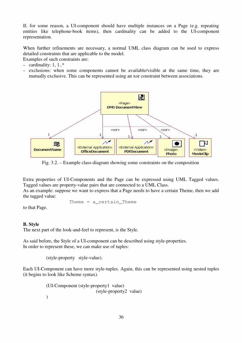
If, for some reason, a UI-component should have multiple instances on a Page (e.g. repeatingentities like telephone-book items), then cardinality can be added to the UI-componentrepresentation.
When further refinements are necessary, a normal UML class diagram can be used to expressdetailed constraints that are applicable to the model. Examples of such constraints are:� cardinality: 1, 1..*� exclusions: when some components cannot be available/visible at the same time, they are
mutually exclusive. This can be represented using an xor constraint between associations.
Fig. 3.2. – Example class-diagram showing some constraints on the composition
Extra properties of UI-Components and the Page can be expressed using UML Tagged values.Tagged values are property-value pairs that are connected to a UML Class. As an example: suppose we want to express that a Page needs to have a certain Theme, then we addthe tagged value:
Theme = a_certain_Themeto that Page.
B. StyleThe next part of the look-and-feel to represent, is the Style.
As said before, the Style of a UI-component can be described using style-properties.In order to represent these, we can make use of tuples:
(style-property style-value).
Each UI-Component can have more style-tuples. Again, this can be represented using nested tuples(it begins to look like Scheme syntax).
(UI-Component (style-property1 value) (style-property2 value)
)
36

A Theme was the collection of all UI-Component Style properties. When we continue using nested tuples this can be formulated as:
(Theme name-of-the-Theme(UI-Component-1 (style-property1 value)
(style-property2 value))(UI-Component-2 (style-property1 value)
(style-property2 value))
)
Actually, instead of using nested tuples, one could also make use of XML to express the Style.An example:
<?xml version=”1.0” ?><theme name=”name_of_the_theme”>
<UI-Component name=”component-1”><style-property name=”property1” value=”value1”/><style-property name=”property2” value=”value2”/>
</UI-Component></theme>
Both notations are equivallent and both can be transformed to a platform-specific style-definition(e.g. CSS, XSL, ...).
C. UI-Component Behaviour
See the next section: section 3.3.2: The Transition Model concepts.
37

3.3.2. The Transformation Model Concepts
What is contained in the Transformation Model?
The Transition Model captures the transitions that take place on a Page and between Pages as aresult of end-user generated events.
By describing the transformations of UI-components on the same Page, the 'Feel' of the Page iscaptured.
By describing the transitions between Pages (like: the loading and unloading of them), a detaileddescription of the implementation of the Conceptual Structural Model is given. The transitions between pages describe which UI-components on a given Page invoke anavigational actions and what the result of that navigation is in terms of loading, unloading of pagesand possible transformations of UI-Components on Pages that are involved in the navigation.
Which concepts are used ?
Two concepts are introduced: UI-Component Behaviour and Page Transisitions.
A. UI-Component Behaviour
The concept of UI-component Behaviour is used to describe the 'Feel' of the UI-components on thePage. This UI-component Behaviour depends on events that occur during user-interaction.
UI-Component Behaviour should capture the change of state (including style if necessary) of UI-Components event that may occur on and within the current Page. Events with a resulting state-of-changes with a scope of multiple pages, should be described in theTransition Model.
A few examples of UI-Component Behaviour:
� When a mouse moves over an Image, the Image should show a big red border.� When a mouse-click event occurs on a menu-text, a collection of menu-items will become
visible.
B. Page Transitions
Page Transitions describe the loading and unloading of Pages and the actions associated with the(un-)loading of a Page.
38
How are these concepts expressed ?
A. UI-Component Behaviour
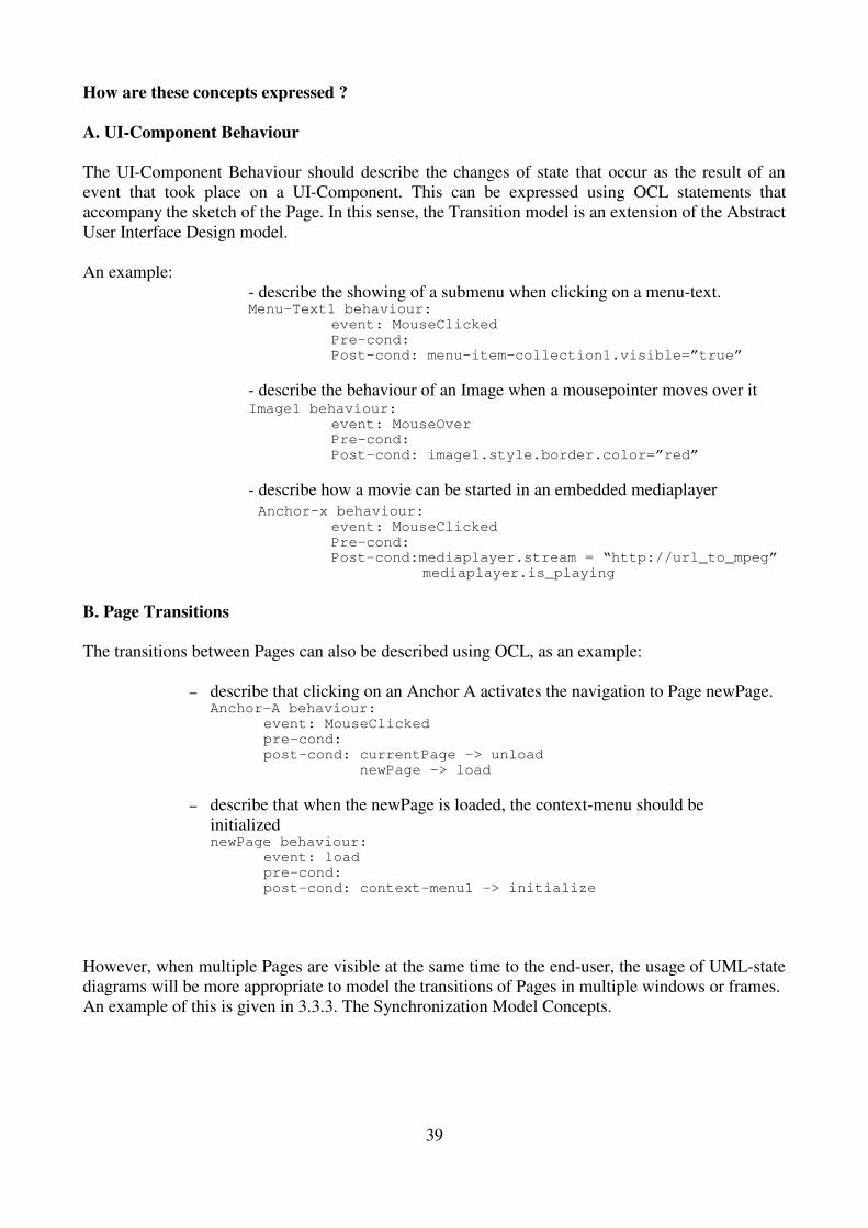
The UI-Component Behaviour should describe the changes of state that occur as the result of anevent that took place on a UI-Component. This can be expressed using OCL statements thataccompany the sketch of the Page. In this sense, the Transition model is an extension of the AbstractUser Interface Design model.
An example: - describe the showing of a submenu when clicking on a menu-text.
Menu-Text1 behaviour:event: MouseClickedPre-cond:Post-cond: menu-item-collection1.visible=”true”
- describe the behaviour of an Image when a mousepointer moves over itImage1 behaviour:
event: MouseOverPre-cond:Post-cond: image1.style.border.color=”red”
- describe how a movie can be started in an embedded mediaplayer Anchor-x behaviour:
event: MouseClicked Pre-cond: Post-cond:mediaplayer.stream = “http://url_to_mpeg”
mediaplayer.is_playing
B. Page Transitions
The transitions between Pages can also be described using OCL, as an example:
� describe that clicking on an Anchor A activates the navigation to Page newPage.Anchor-A behaviour:
event: MouseClickedpre-cond:post-cond: currentPage -> unload newPage -> load
� describe that when the newPage is loaded, the context-menu should beinitializednewPage behaviour:
event: load pre-cond:post-cond: context-menu1 -> initialize
However, when multiple Pages are visible at the same time to the end-user, the usage of UML-statediagrams will be more appropriate to model the transitions of Pages in multiple windows or frames. An example of this is given in 3.3.3. The Synchronization Model Concepts.
39

3.3.3. The Synchronization Model Concepts
What is contained in the Synchronization Model?
If the design of a site dictates that at a certain moment multiple pages of the site have to besimultaneously visible/available to the end-user, then the Synchronization Model can be used todescribe how, when and where the different Pages should be made visible to the end-user. This isthe structure of the Presentation Layer.
For applications that show all Pages in the same window, the Synchronization Model is not needed.
The problem with multiple simultaenous visible Pages is that they need some kind ofsynchronization. Synchronization in this context means: deciding which Pages should be shown atwhat location as a result of a navigational action. Care have to be taken in order to make sure that certain constraints are not violated (e.g. presentingPages from different Audience Tracks to the end-user).
Besides capturing the site's structure of the presentation layer, the Synchronization Model will alsobe used to describe these constraints.
Which concepts are used ?
In order to be able to capture the structure of the presentation layer, three new concepts areintroduced: Window, Frameset and Frame.
A Window is the area of the user interface (e.g. the screen) where Pages are displayed. A windowcan be moved, maximized/minimized, resized, reduced to an icon and/or closed. In addition, awindow also may include a horizontal and vertical scrollbar that allow for visualization of the wholecontent of the window. Windows may overlap other windows, hiding content available in otherwindows.
A Frameset is a modeling element used to define different visualization areas within a window. AFrameset is always contained in a Window. A Frameset is divided into lower level locationelements - called Frames – and may also contain nested framesets. Frames within a frameset cannotoverlap.
A Frame is a visulization area within a Frameset. A Frame can only contain one Page. Frames mayalso include a horizontal and vertical scrollbar that allow for visualization of the whole content ofthe Frame.
A each moment in time only one Window may be the active window; that is: the window thatreceives the end-user input.
40

How are these concepts expressed ?
A. Structural
For each of the three structural concepts: Window, Frameset and Frame, a UML lightweightextension has been defined using the stereotypes: <<Window>>, <<Frameset>> and <<Frame>>.A Window, Frameset and Frame are depicted in the same way as container UI-components.
Fig. 3.3. – Example sketches of a Window with a Page, and a Frameset with Frames
A windows, frameset and frame are also container objects, but there are constraints on what theycan contain. These constraints are shown in fig. 3.4.
Fig. 3.4. – Containment constraints defined on Window, Frameset and Frame.
41

B. Expression of the Synchronization constraints.
During the design of the Presentation Structure, a UML class-diagram, enhanced with constraints,can be used to express the constraints on the visualization of Pages in different Windows andFrames.Fig. 3.5. presents an example of such a diagram. The diagram expresses that in the MainRight-frame, only one of the Pages: SearchAuthor, Author or Article may by visible at a certain moment intime.
Fig. 3.5. – diagram showing example presentation structure constraints
C. Synchronization between pages
In order to show represent the synchronization of the visualization of Pages in Frames andWindows, a UML State-diagram can be used. The example state-diagram as shown below shows that when a button is clicked, then a Window isopened and on opening of that window, a DocumentPage will be loaded.
42

Fig. 3.6. – Example state diagram showing how synchronization can be expressed
43

3.4. Presentation Modeling Language Description
3.4.1. Presentation Design Language
The proposed presentation models of WSDM are expressed using:
� UML stereotyped classes for the page-organization and presentation structure [21][5]� UML state diagrams for interaction modeling [18]� OCL for invariants, pre- and postconditions [24]
Knowlegde of UML class diagrams and state diagrams is presumed. Knowledge of OCL is also presumed; otherwise see [25]
This reference guide is focussed on the design elements used in the Abstract User Interface andSynchronization modeling. These design elements form a lightweight extension to the UML basedon stereotypes.
The different design elements are categorized in several categories:
� user-interaction elements� static elements� multimedia and external application elements� composites
The description of each element will be done using a template containing:
� the name of the element (stereotype)� the visual representation (symbol)� the purpose/description of the element� constraints� tagged values for the description of the state-properties of the element � possible events to which the element responds. If an event is given, then it is one that is
available on all Target Platforms for the application. Per-platform available events can beadded.
� Possible actions that can be performed by the component.
44

3.4.2. Catalog of Modeling Elements
3.4.2.1. User Interaction Elements
User interaction elements are used to represent user-interaction possibilities like: initiatingnavigation, input of text, selection of values, submitting information, ...
Stereotype: <<Anchor>>
Symbol:Description: An anchor is used to represent the starting-point of a navigation. Activation of
the Anchor (e.g. By clicking on it) may result in the unloading of the currentpage and the loading of a new page. Anchors can refer to targets on the samepage. In that case no unloading/loading of a page occurs.
An <<Anchor>> maps directly to a HTML <a> tag.
Constraints: None
Tagged Values: - Text: the text that is shown in the anchor.- Target: the name of the target Window or Frame - Reference: the name of the Page – and optionally a component on it – thatwill be loaded in the Target.
Events: On click On mouseover
Stereotype: <<Anchored Image>>
Symbol:
Description: An anchored image is used to represent the starting-point of a navigation by anImage. The behaviour is the same as with <<Anchor>>.
An <<Anchored Image>> maps to a HTML <a><img/></a> construct.
Constraints: None
Tagged Values: - Picture: the name of the picture to be shown- Target: the name of the target Window or Frame - Reference: the name of the Page – and optionally a component on it – thatwill be loaded in the Target.
Events: On click On mouseover
45

Stereotype: <<Button>>
Symbol:
Description: A Button can be used for two purposes:
- submit information of the form-fields of a <<Form>> to a server- initiate a navigation.
A <<Button>> maps directly to a HTML <input type=”button”> tag.
Constraints: None
Tagged Values: - Text: the text appearing on the button.- ButtonType: the type of the Button: Submit or Reset
Events: On click
Stereotype: <<Textinput>>
Symbol:
Description: A <<Textinput>> element is used to represent a Page-element that enablesuser-input (text, numbers, filenames, ...).
If a <<Textinput>> has only one line, it maps directly to a HTML <inputtype=”text”> tag; otherwise if it contains multiple lines, it is mapped to aHTML <textarea> tag.
Constraints: None
Tagged Values: - Text: the text with which the <<TextInput>> is initialized.
- Lines: the number of lines that are shown in the <<TextInput>> field.
- Columns: the maximum number of characters that are available on each row.
Events: None
Stereotype: <<Password>>
Symbol:
Description: A <<Password>> elements behaves the same as a <<TextInput>> element,except that it masks all the characters entered in the field.
Constraints: None
Tagged Values: None
Events: None
46

Stereotype: <<Choice>>
Symbol:
Description: A <<Choice>> is used to present the user with the possibility of choosing oneor multiple values from a set of options.
There are 3 common ways in which a <<Choice>> is implemented:
- using HTML checkboxes; allowing multiple selections- using HTML radio buttons: allowing only a single selection - using HTML <select> tags, allowing both single and multiple selection.
Constraints: - Number of items in the set of options.
- The possible values of the options.
Tagged Values: - Type: checkbox | radio | select - Selection mode: single or multiple (only applicable with Type = select).
Events: - on click
3.4.2.2. Static Elements
Static elements only show read-only information and don't provide user-interaction facilities.
Stereotype: <<Text>>
Symbol:
Description: A <<Text>> element is used to represent static text on a Page.
A <<Text>> element is mapped to a block of plain text.
Constraints: none
Tagged Values: none
Events: none
Stereotype: <<Image>>
Symbol:
Description: An <<Image>> element is used to represent an image on the Page.
The <<Image>> tag is mapped directly to a HTML <img> tag.
Constraints: None
Tagged Values: - Picture: the name of the Picture to be shown.
Events: - on mouseover
47

3.4.2.3. Multimedia and external application elements
Multimedia elements provide a means for representing the visualization of multimedia-information.External Applications are embedded components in a page that provide access to specializedinformation or specialized actions.
Stereotype: <<Audio>>
Symbol:
Description: The <<Audio>> stereotype is used to represent the replay of audio fragments.
Two possible uses of this tag exist: - or the sound is used as a background sound and plays automatically whenthe Page is loaded en stops when the Page is unloaded or when a certainnumber of iterations is reached. - or a multimedia player for sounds is presented to the end-user, allowing theend-user full control over the replay of the sound.
Constraints: This element is not available for all platforms.
Tagged Values: - sound: a uri pointing to the sound file or stream- type: Background or Interactive- number of repetitions: the number of times the sound has to be replayed (onlyapplicable with audio-type = Background
Events: On click: when the user clicks one of the controls of the player (only ininteractive mode)
Actions: - play
- pauze
- stop
Stereotype: <<Video>>
Symbol:
Description: The <<Video>> stereotype is used to represent the possibility of replayingvideo fragments in the Page using an embedded player.
Constraints: This element is not available for all platforms.
Tagged Values: - stream: a uri pointing to the incoming video-stream
Events: On click: when the user clicks one of the controls of the player.
Actions: - play
- pauze
- stop
48

Stereotype: <<External Application>>
Symbol:
Description: An <<External Application>> modeling element is used to represent anautonomous component, designed to perform very specific tasks which cannotbe performed easily or at all using the other Stereotypes.
An <<External Application>> is usually mapped to a HTML <object> or<applet> tag.
Constraints: The type of <<External Application>> that can be used depends on the targetplatform.
Tagged Values: - type: ActiveX | Applet- source: a URI pointing to the files containing the implementation of the<<External application>>
Events: None. All user interactions with the <<External Application>> component arehandled by the component itself.
Actions: Depend on the instance of the Component.
49

3.4.2.4. Composites
Composites are design elements that are constructed out of other design elements. Some of themmay be nested and some of them are useful for modeling groups of elements that may occur severaltimes on different pages.
Stereotype: <<Page>>
Symbol:
Description: A <<Page>> is used to represent the static organization and possiblecombinations of the elements on a page.
A <<Page>> can contain any mix of static elements, anchors, forms,multimedia elements, external application components and <<frames>> (in thecase of a <<Frame>> on a <<Page>>, the <<Frame>> is mapped to a HTML<iframe> tag.
Besides the elements described above, a <<Page>> can also contain logic inthe form of scripts. The invariant properties, pre- and post-conditions of theexecution of a page-script can be described using OCL.
Constraints: Not all platforms support the embedding of <<Frame>> on a <<Page>>.
Tagged Values: - Title: the title of the page.
Events: On load
On unload
On click
Stereotype: <<Collection>>
Symbol:
Description: A <<Collection>> is used to group reoccurring combinations of page and/orform elements.
A <<Collection>> enables the composition of “custom” components and alsoenables the reuse of combinations of components on multiple pages.
When a <<Collection>> is built, it is given a name. <<Collection>>s are builtindependent of the <<Page>> in which they are referenced by name.
Constraints: None
Tagged Values: None
Events: Depends on the components used to build the <<Collection>>.
50

Stereotype: <<Anchor Collection>>
Symbol:
Description: The convenient <<Anchor Collection>> is a specialized type of<<Collection>> in that it only contains <<Anchors>>-like elements.
<<Anchor Collections>> are typically used to represent menus, navigationcues, or just a collection of <<Anchors>> that are related to each other in agiven context.
Constraints: May only contain <<Anchors>> and/or <<Anchored Images>>
Tagged Values: None
Events: On click, as defined on each <<Anchor>> in the collection.
Stereotype: <<Window>>
Symbol:
Description: A <<Window>> represents a standalone container that can only contain one<<Page>>.
Without a <<Window>> (or <<Frame>>) a <<Page>> cannot be made visible.
An application can make more than one <<Window>> available to the end-user, but only one <<Window>> can have the input focus.
In reality, a <<Window>> maps to a single Browser window containing one<<Page>>.
<<Windows>> containing multiple <<Pages>> are modelled using a<<Frameset>>.
The <<Window>> stereotype can also be used to describe the possible<<Page>>s that can be presented in a given <<Window>> instance.
Constraints: A <<Window>> can only contain one <<Page>> at the time.
Tagged Values: - Page: the name of the Page that is presented using the <<Window>>.
Events: - on Open
- on Close
Actions: - activate
51

Stereotype: <<Frameset>>
Symbol:
Description: A <<Frameset>> is an alternative to a <<Window>> used for modeling theconcurrent presentation of multiple <<Page>>s in a single <<Window>>.
<<Frameset>> are constructed out of <<Frame>>s and can also contain other<<Frameset>>s.
Constraints: A <<Frameset>> organizes its children in rows or columns; but not both at thesame time.
Tagged Values: - Rows: the number of rows in the frameset.
- Columns: the number of columns in the frameset.
Events: None
Stereotype: <<Frame>>
Symbol:
Description: A <<Frame>> is used to present a single <<Page>> in the context of a<<Frameset>> or within another <<Page>>.
The <<Frame>> stereotype can also be used to describe the possible pages thatcan be contained in the <<Frame>> using a UML class diagram in which therelation between the <<Frame>> and its possible <<Pages>> are constrained(xor-ed).
Constraints: None
Tagged Values: - Page: the name of the <<Page>> contained in the <<Frame>>
Events: None
Stereotype: <<Form>>
Symbol:
Description: A <<Form>> is a collection of input fields (<<textinput>>, <<pasword>>,<<choice>>, <<button>>).
A <<Form>> maps directly to a HTML <form> tag.
A <<Form>> is used to collect information entered manually by the end-user.
Constraints: None
Tagged Values: - Target: the name of the Window or Frame that should show the response ofthe form-data processing process.
- Method: Post or Get
- Action: the name of the 'program' (= server page, script or program) that isresponsible for processing the submitted form-data.
Events: - on submit
Actions: - submit
52

3.5. WSDM Presentation Design Guide
In order to complete the Presentation Design Method according to Rumbaugh's definition of aDesign Method (see section 3.1), a presentation design guide will be proposed. This guide is built out of a number of steps which are accompanied by some rules-of-thumb that canhelp de designer make decissions about the style, UI-components, layout, etc... to use.
Care has been taken in that the models created during the different steps of this guide are driven bythe models and concepts as found in the previous design phases of the WSDM Method; as will beexplained later.
The purpose of this guide is to describe a process for generating the three different PresentationDesign models:
1. The Abstract User Interface Model,2. The Transition Model 3. The Synchronization Model
The process that is described in this guide builds those three models in the order as specified above,but starts with the specification of some site-global user-interface rules that should be applied to allpages within the application.
An overview of the guide is given in the next table:
Step Description1 Determine site-global user-interface rules and constraints like: the target platforms,
the default theme, internationalization, the use of a single window or showingmultiple pages at once, global page-layout rules.
2 Determine the different pages to be build, following the navigation tracks peraudience class.
3 Create a model of Pages that are reachable from all other Pages. Examples are: thehome- or frontpage, the site-map, index pages, contact information page, ...
4 Create a model of the global site-menu and context-menus based on the structurallinks and process logic from the conceptual structural model, in combination with theoutput of step 3.
5 Search, define and make a model for combinations of UI-components that can bereused on different Pages. Good candidates are: search-forms, login-forms, logo,headings, footers.
6 Create a model of the pages per audience track based on the information and taskmodels found per audience track.
7 Create the Transition model by defining the behaviour of UI-component per page.
8 Create the Synchronization model by specifying the windows and frames that will beused, together with the constraints on the visualization of the Pages in each windowor frame.
53

In steps 1 to 6 the Abstract User Interface Model is built.In step 7 the Transition Model is definedIn step 8 the Synchronization model is built; this is only necessary for applications that have to dealwith simultaneous visualization of different Pages.
Step 1 – Determine site-global user-interface rules and constraints
On every good designed website, no matter how big or small, the implementation of each pageadheres to some – possibly unwritten – rules that act as a guidance for the developper during theimplementation of the Pages.
These rules are general of nature, and apply to all pages of the website. It is a good practice to capture these rules before starting the actual construction of the threepresentation models, because these rules can put restrictions on the kind of UI-components that canbe applied, the use of multiple windows or frames, etc.
Four of these general, site-global rules are worth to be taken into consideration because they have abig impact on the implementation of the site.
The rules in question give guidance about:� the possible target platforms on which the site should be deployed� the Themes to be used� the way internationalization aspects are handled� the use of windows and frameset. � the default page layout
These rules can originate from multiple sources, like:� the company's external or internal communication styleguide� the characteristics of the target audience class � the kind of devices that are available to the end-user (e.g. In a transport firm, each trucker can use
a wireless connected tablet-PC or a WAP-enabled GSM to communicate with the company'swebsite).
a. Determination of the target platforms
If a site, or parts of it, are to be implemented on different target platforms, then it is agood idea to identify these platforms. The identification of the platforms can consist of:
� the name of the target platform: web-browser, PDA, WAP-device (e.g. GSM), ...� the available maximum resolution for windows or framesets; or the maximum resolution
that will be taken into account. � Number of available colours (e.g. Some devices only support black-white)� ...
The characteristics of the target platform can put a constraint on the possible UI-components thatcan be used, the number of available colours, the possibility to use multiple windows or framesets,the maximum size of areas on the screen in which a page can be shown, etc...At least those characteristics of the target platform that can be used to constrain the design of pagesa the conceptual level, should be noted.
54

Example:� the pages of the audience track: "Dietician" should be implemented on a mobile device (palmtop
or tablet computer) without a keyboard or mouse; the dietician can only use a stylus for user-interaction.
This places constraints on the size of the pages as well as on the input-medium thatcan be used. In this case it is only a stylus; so al lot of textual input should be avoided.
� the latest news from the weather forecast website should be browseable using a WAP-device.This places constraints on the size of the pages. WAP devices also implay that onlya single (conceptual) window can be used for the visualization of pages. The available number of colours is also restricted to 2 (black/white) on most WAP devices.
b. Define the default and alternative Themes (see 3.3.1) for the site.
The default Theme will be indirectly applied to al Pages, unless it is otherwise specifiedper Page. The exact definition of the Themes can be done during the implementation phase, but it'sgood to know what Themes the designer has in mind.
At least these themes should be defined:
� Default Theme: If this consists of standard OS or browser related styles for the UI-components,then no further detail is needed. In all other cases, the Default theme should be described in thesame way as the Alternative Themes (see next).
� Alternative Themes: � these should be given a name� the 'scope' of the Theme should be given: is the theme applicable to the whole site or only
on certain audience tracks.� The alternative Themes should contain a definition of which style-attributes are to be
applied on which UI-components. The definition of these (UI-component – style-attribute) associations can be delayed until implementation time.
c. Define how Internationalization will be handled.
If a site has to be presented in different languages (e.g. For the different audienceclasses), then the applicationlayer that is most sensitive to this is the presentation layer. As such,the internationalization aspects of the presentation layer must be taken into account. Two approaches are commonly used:1. Build a 'copy' of the website for each different language.2. Build a 'template' website with pages containing fields that are at runtime configured with the
text in the language of the end-user.The first approach is easiest to model: only one model is needed and it can be copied for eachsupported language. However, there will be maintainance problems: a change on one or more pagesmust be hand-crafted in all versions of the site. There are some situations in which this approach isthe only viable: if the way text is read is complete different in two applicable language – e.g. left-to-right/top-to-bottom vs. Bottom-to-top/right-to-left) then it is quite possible that the structure of thepages cannot be kept for all languages.
55

The second approach is more elegant, since it can be built on the separation of content andpresentation: if a page is needed in language X, use the template of the page, fill in the fields withthe text translated in language X and done. This approach only uses one presentational model andrequires only one implementation of it, so maintenance will be simpler.
If the target audiences are distinguished by their mother language, then a separate set of presentationmodels should be designed; one for each audience track.
d. Decissions about the usage of windows and frameset.
The rule that is defined here is the answer to the question: will all Pages of the site be shown in thesame window, or can multiple simultaneous visible windows or frameset be used to structure thepresentation of the pages?
Different answers to this question have different impacts. Example answers are:
Answer 1: All pages must be shown in the same window.Consequences:
� no need to create the synchronization model� it is very likely that the pages reach long lenghts, forcing the end-user to scroll so the
global site-menu or context menus will disappear. When designing pages, thisshould be taken into account (e.g. By adding extra links on the page to the locationof the menus on that page.
Answer 2: A frameset is used to visualize all pages.Consequences:
� a synchronization model should be created, showing which page can be made visiblein which frame.
� The available screen-space for showing each Page is restricted (because there can beno overlappings of Pages).
� Structure of the frameset and the names of the different Frames should be specifiedusing a sketch.
Example Frameset setup:
Fig. 3.7. - Example frameset setup
56

Answer 3: Multiple windows are used to visualize the pages.Consequences:
� a synchronization model should be created, showing which page can be made visiblein which window.
� Windows can overlap; hiding information available in other windows.� The screen can become cluttered when a lot of windows are opened a the same time.� The different windows should be named.
e. Define the default page layout.
The default page layout is a description of the rules to which the layout of each page shouldconform. If multiple page-layouts are allowed within the site (e.g. A layout per audience class), then eachpage-layout should be described in terms of page-layout rules.
A Page-design time, these rules should be applied.
Possible items contained in the default page layout can be:
� the availability and placement of the logo on a Pagee.g. The logo is always shown in the top-left corner
� the location of the global site navigation menu on a Pagee.g. The global site navigation menu is located on top of the Page
� the location of search-input fields on a Page e.g. A search-input field is provided at the right margin of the Page, next to the globalsite navigation menu.
� the positioning of images on a Page e.g. When a page contains only one image, the image is centered on the page. When a page contains more than one image, the images must be equaly spread on a diagonal (top-left to bottom-right).
� the location of context menus on a Page e.g. The context menu is located at the left-hand side of the Page
� the usage of headers and footers on a Page e.g. Each page has a footer containing only the name of the company, the name of Page and the moment on which the page was last changed.
� etc...
57

Step 2 – Determine the different pages to be built per audience class
In this step, all Pages that should be implemented are identified based on the conceptual structuralmodel.
The result of this step is a complete overview of all pages that need to be implemented. This information can be used to construct the global site menu, index pages and the sitemaps.
Besides a conceptual design purpose, this overview can also become handy for the management ofthe implementation of the website because:� it can be used to control the spreading of implementation of the pages over multiple
programmers� it can be used as a measure for the progress of the implementation� it can be used to estimate the total time needed to implement the website
This overview can be generated in a five-step process:1. Find index pages per navigation track; if any.2. Per navigation Track, define a Page for each component found in the Task models3. Find extra navigation-supporting pages based on the navigational aid links4. Find other Pages that have little or no relationship with the conceptual model, but are part of
the website.5. Solve possible ambiguities.
1. Find index pages per navigation track, if any
Fig. 3.8. example conceptual structural model
The existence of index-pages can be deduced from the conceptual structural model: for everyoccurance of a one-to-many uni- or bi-directional link, an index page for the navigation track at theone-end of the link can be constructed (see also fig 3.11. – PC-Chair track). [26]
58
Visitor Track
Un-RegisteredUser Track
Registered User Track
PC-chairTrack
Author Track
Fully RegisteredUser Track
Pre-RegisteredUser Track
ReviewerTrack
PC-MemberTrack
C1: visitor is not fullRegisteredC2: visitor is fullRegisteredC3: visitor is PC-ChairC4: visitor is Reviewer or p in PC-MemberC5: visitor is PC-MemberC6: visitor is PC-Author
C1
C2 C3
C4
C5
C6
Visitor Track
Un-RegisteredUser Track
Registered User Track
PC-chairTrackPC-chairTrack
Author TrackAuthor Track
Fully RegisteredUser Track
Pre-RegisteredUser Track
ReviewerTrackReviewerTrack
PC-MemberTrackPC-MemberTrack
C1: visitor is not fullRegisteredC2: visitor is fullRegisteredC3: visitor is PC-ChairC4: visitor is Reviewer or p in PC-MemberC5: visitor is PC-MemberC6: visitor is PC-Author
C1
C2 C3
C4
C5
C6

Fig 3.9. – symbols representing one-to-many structual links.
The index pages found in this way should be added to the overview.
Suppose that the Visitor Track, PC-chair Track and Author track each have an index-page, then weadd to our overview:
Visitor Track IndexPC-chair Track IndexAuthor Track index.
2. Per navigation Track, define a Page for each component found in the Task modelsAs an example the task model for a task: Submit New Paper (part of the Author Track) is used:
Fig. 3.10. - Task model for Submit New Paper task.
In the task model, each elementary task is represented by a component (shown in a rectangle).For each component in a task model, a corresponding Page must be created.
The task: Submit New Paper has three components: � Register NewPaper� SubmitPaper Info & File� Add Co-Author
Fore each of these three components, a Page should be constructed:� Register New Paper Page� Submit Paper Page � Add Co-Author Page
3. Find extra navigation-supporting pages based on the navigational aid links in theconceptual structure model
� When a link to the Homepage is found, then the Homepage should be added to the overview ofPages to be built.
� When links to sitemaps are found, for each sitemap a Page should be designed; so these must beadded to the overview too.
59
Submit Paper
Info & File
Add Co-Author
RegisterNewPaper
Submit New Paper

Fig. 3.11. – pc-chair track.
4. Find other Pages that have little or no relationship with the conceptual model, but are partof the website.Candidate pages are mostly pure static (HTML) pages:
� the contact information page of a company� a route-description� ...
5. Solve ambiguities.
This means: if two pages found in one of the previous steps are conceptually the same, then oneof them needs to be eliminated.
An example of ambiguity can be: the Visitor Track Index and the Homepage. Both of these pages are conceptually the same, so only one name has to be used for this page. For convenience we name it: Homepage.
An (minimized) example of a resulting overview can be:
Visitor Track:HomepageContact Information Page Route description Page Login Page
Unregistered User Track:Register New User Page
Registered User Track:Login Page
Pre-registered User Track:Confirm Registration Page
Fully Registered User Track:Fully Registered User Track Index
PC-Chair Track:PC-Chair Track Index...
60
PC-Chairtrack Conference
PC-Members& Reviewers
Papers
AuthorsAuthors
ReviewsReviews
PC-MeetingPC-Meeting
H L
L
L
L
L
L

PC-Member Track:...
Reviewer Track:...
Author Track:Author Track IndexRegister New Paper Page Submit Paper Page Add Co-Author Page ...
61

Step 3 – Modeling of global reachable Pages
In this step, the pages that are globally reachable (this means: reachable from each other page withinthe website) are modelled.
There are two kind of pages that need to be modelled, namely: � pure static pages with no direct relation to the conceptual models
Examples of these are:� the contact information page � the route description page.
The constraints that are applicatble to these pages are defined by the rules ascaptured in step 1 of this presentation design guide.
� pages with a direct relation to the conceptual models; in casu: pages that are built inorder to support and enhance the navigation through the site. Candidate pages are: the homepage, sitemaps and index pages.
1. The construction of the homepage
The homepage should conform to the page-layout rules as defined in step 1 of this guide.
The most important thing to model on the homepage, are the links to the different navigation tracksin the site.
One approach for the construction of the Homepage is based on the Audience Class Hierarchy. Thepurpose is to represent the different audience classes in some way on the homepage in order toallow a user that fits in a certain audience class to navigate directly to his navigation tracks.
Fig 3.11. – Sample audience class diagram with variants.
62
Lecturer PotentialStudent
Enrolled Student
EnrolledDistanceStudent
PotentialDistanceStudent
English Speaking
Dutch Speaking
Visitor
Lecturer PotentialStudent
Enrolled Student
EnrolledDistanceStudent
PotentialDistanceStudent
English Speaking
Dutch Speaking
Visitor
English Speaking
Dutch Speaking
Visitor

As can be seen in Fig 3.11., variants of Audience classes can also exists (in the example, thevariance is based on the mother language of the Visitor). If the website provides a version of thenavigation tracks and pages that is adapted to these Audience Class variants, then a shortcut to thesealternative implementations should be added on the Homepage.
Besides links to audience tracks, the homepage can also contain information about the company ororganization, links to other pure static pages (like contact information or route description pages),the mission statement of the website, a logo, etc.
If the site requires authentication before certain navigation tracks become available, than a link to alogon-page, or a login-form, should be added to the homepage.
The homepage can be seen as the main menu of the website. The concrete modeling of the menuswill be discussed in step 4 of this guide.
2. The construction of a index pages.
Index pages are used to give a one-shot overview of the different navigation tracks a user can followfrom a certain location within the website. Index pages mostly occur at the start of an audiencetrack.
The links that should be added to an index page are indicated by landmark navigational aid links inthe conceptual structural model.
Example:
Fig. 3.11. – pc-chair track.
As can be seen in the diagram presented in Fig. 3.11., a one-to-many uni-directional link from thePC-Chair Track to the specific PC-Chair navigation tracks is used. This indicates that at the start ofthe PC-Chair track an index Page should be available to give an overview (and at the same timeaccess) to the different available navigational options from then on.
63
PC-Chairtrack Conference
PC-Members& Reviewers
Papers
AuthorsAuthors
ReviewsReviews
PC-MeetingPC-Meeting
H L
L
L
L
L
L

Following the landmark navigational aid links in the given model, the PC-Chair Index Page shouldcontain a link to the
� conference track� pc-members and reviewers track � papers track � author track � reviewers track � pc-meeting track
An index page acts as a menu, representing navigational choices. For the concrete modeling of themenus, see step 4 of this guide.
3. The construction of sitemaps.
A website can have more than one sitemap; each built with a specific purpose or target audience inmind.
Before constructing a sitemap, a few decissions have to be made concerning the content of thesitemap:� What is reflected using a sitemap? � The hierarchical link-structure of the website?� An alternative overview of the website, not following the hierarchical link-structure?
� For which target audience class is the sitemap constructed?� The Visitor audience class?� The Author audience class ?� ...
For each audience class a customized sitemap can be defined containing only shortcuts (links)to relevant information and functionality required by that Audience Class.
No matter what the content is of a sitemap, conceptually it is a page full with links to other pageswithin the website.
The easiest way to construct a sitemap is to search the conceptual structural model for thenavigational aid links: H and L (Home an Landmark) and put them all together on one page;organized per audience track.
These links can be represented using Anchor UI Components and can be grouped AnchorCollections. By nesting Anchor Collections, a hierarchical menu (or tree) can be modelled.
64

Step 4 – Modeling of global site menu and context menus
1. The global site menu
The global site menu is a menu that appears on all pages of the website, making the targets of thelinks in that menu reachable from within each page.
It is therefor a good idea to model this menu separately as a reusable component.
The links that should be available on the global site menu are most probably the same links as thosethat appear on the Homepage (defined in step 3). Otherwise, the global site menu can also beconstructed starting from the overview of the different navigation tracks, as given in the exampleschema below:
Based on this scheme it can be decided which tracks should be globally reachable, e.g.:� The Visitor Track (pointing to the Homepage)� The PC-Chair Track � The Reviewer Track � The PC-Member Track � The Author Track
But, as can be seen in the conceptual structural model, sometimes some conditions apply before aTrack should be reachable. This indicates that a global site menu should be adaptable in order toreflect the audience classes of the current user; once the user is known to the application.In the presentation design of the global site menu, we can describe these adaptions using OCLinvariant constraints.
Besides links to navigation tracks, the global site menu can also contain links to individual pages(e.g. A link to the contact information page).
65
Visitor Track
Un-RegisteredUser Track
Registered User Track
PC-chairTrack
Author Track
Fully RegisteredUser Track
Pre-RegisteredUser Track
ReviewerTrack
PC-MemberTrack
C1: visitor is not fullRegisteredC2: visitor is fullRegisteredC3: visitor is PC-ChairC4: visitor is Reviewer or p in PC-MemberC5: visitor is PC-MemberC6: visitor is PC-Author
C1
C2 C3
C4
C5
C6
Visitor Track
Un-RegisteredUser Track
Registered User Track
PC-chairTrackPC-chairTrack
Author TrackAuthor Track
Fully RegisteredUser Track
Pre-RegisteredUser Track
ReviewerTrackReviewerTrack
PC-MemberTrackPC-MemberTrack
C1: visitor is not fullRegisteredC2: visitor is fullRegisteredC3: visitor is PC-ChairC4: visitor is Reviewer or p in PC-MemberC5: visitor is PC-MemberC6: visitor is PC-Author
C1
C2 C3
C4
C5
C6

Links in the abstract user interface model are represented using an Anchor UI component. As the global site menu is a collection of links, an Anchor Collection component is best suited.
Example:
� PC-Chair anchor:� inv: if user is a PC-Chair
then PC-Chair anchor.visible = true else PC-Chair anchor.visible = false
� Reviewer anchor:� inv: if user is a Reviewer
then Reviewer anchor.visible = true else Reviewer anchor.visible = false
� PC-Member anchor:� inv: if user is a PC-Member
then PC-Member anchor.visible = true else PC-Member anchor.visible = false
� Author anchor � inv: if user is an Author
then Author anchor.visible = true else Author anchor.visible = false
Fig 3.12. - Example Global Site Menu
When constructing Pages (step 5), the global site menu can be referenced using this symbol:
2. The context menus
Context menus are menus that are specific for a certain navigational context, like a navigation trackof a certain audience class. Context menus contain the same links as the index page of a navigation track, but are modelled as areusable component because they appear on each page within the track. The context menu can also contain a reference to the index page of the navigation track.
Example
The context menu of the pc-chair navigation track can be modelled as this:
66

Fig. 3.13. - Example context menu
And on each page of the navigation track it can be referenced using:
67

Step 5 – Modeling of reusable User Interface components
If there are grouping of UI-Components that appear on multiple – if not all – pages of the website,then a separate modeling of these groupings is adviced, because:
� each grouping needs only to be modelled once� by creating a separate model for that grouping, it can be easily reused� only one model needs te be updated if the composition of that grouping changes.� Using references to pre-build models makes the design of a Page more readable.
Modeling groupings of UI-Components can be done by defining a <<Collection>> class thatrepresents that grouping.
A number of possible candidate are:� a location bar: a location bar is a component on a page that consists of a number of
Anchors, where each Anchor represents a step in the path the user has followed inorder to reach that page. Since the content of a location bar can change with eachpage, the behaviour of the location bar in function of the navigation context shouldbe described using OCL.
� A login form: in most cases this contains a username field, a password field and aButton to initiate the authentication. If a login-form is present on multiple pages, itshould be modelled separately. The login form should also be accompanied with adescription of the resulting page that will be loaded when the authentication wassuccessful or failed.
Login Form� if fail(login) then load logon-error Page� if success(login) then load user-main-menu-Page
Fig. 3.14. - Sample Login Form
� When a site presents a site-wide search functionality and each page contains a searchform, then this search form should be modelled separately. An simple search formcan be modelled as such:
Fig. 3.15. - Simple Search Form
When constructing a Page, the SimpleSearchForm can be represented using:
68

Step 6 – Modeling of the Pages per audience track
What has already been done up 'til now? In step 2 of this guide, all pages that need to be modelledin the Abstract User Interface model are determined. This overview contained both pure navigationsupporting pages like the homepage, sitemaps and index pages, as well as pages that are used torepresent tasks in the task models per audience track.
The homepage, sitemaps, index pages, menus and reusable components are modelled in steps 3 to 5.
In this step, all Pages from the overview generated in step 2, that are related to a Task in theconceptual model related pages, will be modelled.
For each Task-related Page, build a Page-model using following procedure:1. Use a template, or build a basic Page model that conforms to the rules and constraints as
captured during step 1 and add the global and context menus and possible custom reusablecomponents as modelled in step 3 of this guide.
As an example, a Page is modelled for the Task: "Submit Paper Info and File"
The basic Page model:
Page's tagged values: Theme = DefaultFig. 3.16. - Sample template or basic Page.
69

2. Determine the links that should be added to the Page.
Lookup the conceptual Task model that contains the Task to be modelled.
Fig 3.10. Task model for "Submit new paper" Task.
From this task model, we can detect the the possible navigations that start from this page. As can beseen in the task model, there are two links with the "Submit Paper Info & File" component assource:
� a link to the Add Co-Author Page (represented by the Add Co-Author component)� a link used to exit this task; for example by returning to the index page.
Exiting the task can already be done by following links in the context or global site menu. For the navigation to the Add Co-Author page, a navigational component should be added to thepage. This can be represented using:
� an Anchor� an Anchored Image
3. Determine the information that should be shown and the information that must be entered by theend-user and how the input should be represented
Lookup the information chunk that is related to the conceptual Task (see next page). This chunkdescribes what information is realy needed to execute the task.
From the viewpoint of presentation design, this chunk shows two kinds of information:
� information that only needs to be visualized� information that must be supplied by the end-user (input-information).
70
Submit Paper
Info & File
Add Co-Author
RegisterNewPaper
Submit New Paper

Fig. 3.17. - Information chunk for "Submit paper info and file" task.
The information that needs to be supplied by the end-user is marked with the ORM extra notationfor user input: ? and ?? .
The lexical object that are marked this way are:� the name of the Track (*tr)� the subject ({*s})� the abstract (*a)
Both can be mapped to a Textinput UI-component.
Another lexical object that requires user-input, is the File (URL) lexical object, which is assigned avalue through the an upload of a document (*f = UPLOAD)
� the File-url (*f).For this application, a new UI-Component type can be defined in several ways:
a) Use inheritance for defining a subtype of Textinput UI-component that adds a Browse-for-file Button to the Textinput component (making use of inheritance). Add a <<Fileupload>> stereotype to this subtype.b) define a new Collection, named: Fileupload, containing a Textinput and Button UI- componentc) just use a Textinput and Button UI-component
In this case, there will be choosen to use the Fileupload subtype of a Textinput UI-component.
71
+
+
++
+
+
+
+
++
+
+

Information that only needs to be shown in this Task's page is found by the other lexical objects:
� paper title� paper id
(both are defined in the previous task: "Register new Paper").
and� submission date� last modification date
Both of these fields are contrained in that their value is assigned to the current date (*d = TODAY).
The information: paper title, paperid, submission date, and last modification date can all be mappedto a Text UI-component.
4. Integrate the results of (2) and (3) with the basic-Page as described in (1).
Since Textinput components can only exist in a Form, a Paper-submission Form is defined. The other UI-components are placed directly on the Page.
The resulting Page-model is:
Fig. 3.18. - Resulting modelled Page for the "Submit Paper info and File" task.
72

Step 7 – Create the Transition model
The transition model describes the behaviour of page-elements during the interaction with the end-user. As described in chapter 3, section 3.3.2, in the transition model, each page is extended withconstraints (expressed in OCL) that describe the behaviour of UI-components on the page and thetransition of pages.
In order to create the Transition model, each Page-model that is created in Step 6, must be extendedwith OCL constraints describing the behaviour of the UI-components and Pages during user-interaction.
The Transition Model for the "Submit Paper Info and File" Page can be:
� Anchor("Add Co-Author")event: MouseClickedpre:post: currentPage -> unload page("Add Co-Author") -> load
� Button("Submit") event: MouseClicked pre: Form("Paper Submission Form").action = some_action post: submit information to Form("Paper Submission Form").action
currentPage -> unload "Add Co-Author"-Page -> load
73

� FileUpload("File"):
event: MouseClicked pre: post: FileSelectionBrowser -> show
Fig. 3.19. - Page model with transitions added.
Step 8 – Create the Synchronization model.
Create the Synchronization model by specifying the windows and frames that will be used, togetherwith the constraints on the visualization of the Pages in each window or frame.
1. Determine the windows to be used
2. If a frameset will be used, then determine how the frames in the frameset are organized. Give
each frame a name
3. Create a UML class diagram in which is shown which pages can be shown in which window or
frame. Every Page that is discovered in step 2 should be associated with the windows or frames in
which it will be visualized.
4. Create a UML statechart showing the transitions of the pages in the frames and windows.
An example of these models can be found in chapter 3, section 3.3.3.
74

Conclusion
In this paper, a design method and a notation for the presentation design of WSDM is proposed. The construction of the method follows a definition of 'design method' (Rumbaugh) that iscommonly applicable to other design methods for web applications.According to that definition of design method (see 3.1), a set of concepts and models is defined thatcapture the semantics in the presentation layer and the proposed method also provides guidance forthe construction of the presentational models.
Although I think that the proposed method is quite complete, and leads to good results, there arestill some things that requires some deeper examination, For example: � The modeling of transactions within the transition model and synchronization model.� The method doesn't support reverse engineering an existing site. Reverse engineering could be
useful when existing sites need to be remodelled, but no analysis nor design of the existing site isavailable.
� I suppose that the presentation models are intended to be used as an important startpoint for thegeneration of parts or the whole of the implementation. Although the notation is based on UML,and the design-method is object-oriented, it has not been verified whether is is possible togenerated code based on the models as described in this paper. I also don't know to what level ofdetail we must go on the conceptual level in order to provide enough 'design' or 'meta'information for allowing correct generation of platform dependent code. This requires furtherresearch.
.
75

References
[1] De Troyer, O., Leune, C.: "WSDM: A User-Centered Design Method for Web Sites", InComputer Networks and ISDN systems, Proceedings of the 7th International World Wide WebConference, Elsevier, pp.85-94(1998)
[2] De Troyer, O., "WSDM – Web Site Design Method", presentatie,http://wise.vub.ac.be/Download/Courses/OntwerpMethoden/wsdm-2004-1.ppt
[3] De Troyer, O., "WSDM – Web Site Design Method", presentatie,http://wise.vub.ac.be/Download/Courses/OntwerpMethoden/wsdm-2004-1.ppt, p.101
[4] Koch N., Kraus A. and Hennicker R. (2001) The Authoring Process of the UML-based WebEngineering Approach, In First Internation Workshop on Web-Oriented Software TechnologyIWWOST'2001, Valencia
[5] Koch N. (2001) Software Engineering for Adaptive Hypermedia Applications, PhD. Thesis,Reihe Softwaretechnik 12, Uni-Druck Publishing Company, Munich.http://www.pst.informatik.uni-muenchen.de/personen/kochn/PhDThesisNoraKoch.pdf
[6]Koch N. and Kraus A. (2002). The expressive Power of UML-based Web Engineering. Proc. OfIWWOST'02, CYTED, pp.105-109.
[7]Baumeister H., Koch N, and Mandel L.: Towards a UML extension fo hypermedia design. Inproceedings <<UML>>'99, France, R., Rumpe, B. (eds), LNCS, Vol. 1723. Springer-Verlag (1999)614-629. ===> NAKIJKEN (ik heb nog een ander exemplaar van deze tekst).
[8] S. Ceri, P. Fraternali and A. Bongio (2000), “Web Modeling language (WebML): a modelinglanguage for designing Web sites”, Dipartimento di Ellettronica e Informazione, Politecnico diMilano, Italy.
[9] S. Ceri, P. Fraternali, M. Matera, A. Maurino (2001) “Designing Multie-Role, CollaborativeWeb Sites with WebML: a Conference Management System Case Study”. IWWOST'01, Valencia,Spain, June 2001.. [10] J. Gomez, C. Cachero and O. Pastor (2001), “Conceptual Modeling of Device- IndependentWeb Applications”, http://www.dsic.upv.ex/~west2001/iwwost01/files/contributions/JaimeGomez/ieeeMultimedia.pdf
[11] J. Gomez, C. Cachero an O. Pastor (2001), “Extending a Conceptual Modeling Approach toWeb Application Design”, http://www.dsic.upv.es/~west2001/iwwost01/files/contributions/JaimeGomez/caise00.pdf
[12] C. Cachero, J. Gomez and O. Pastor, “Object-Oriented Conceptual Modeling of WebApplication Interfaces: The OO-H Method Abstract Presentation Model”,http://gplsi.dlsi.ua.es/iwad/ooh_project/papers/ecweb00.pdf
76

[13] J. Gomez (2003), “OOH-Method: Extending UML to Model Web Interfaces”,http://gplsi.dlsi.ua.es/iwad/ooh_project/papers/igp02.pdf
[14] Daniel Schwabe and Gustavo Rossie, “An Object Oriented Approach to Web-BasedApplication Design”, Theory and Practice of Object Systems 4(4), 1998. Wiley and Sons, NewYork, ISSN 1074-3224
[15] D. Schwabe and G. rossie (2001), “The Object-Oriented Hypermedia Design Model(OOHDM)” - http://www.telemidia.pucrio.br/oohdm/oohdm.html
[16] D. Schwabe, R. de Almeida Pontes and I. Moura, “OOHDM-Web: An Environment forImplementation of Hypermedia Applications in the WWW”, Dept. Of Informatics, PUC-Rio,http://www-di.inf.puc-rio.br/~schwabe/papers/SigWeb-OOHDMWeb.pdf
[17] G. Rossi, D. Schwabe, C.J.P. Lucena and D.D. Cowan, “An Object-Oriented Model forDesigning the Human Computer Interface of Hypermedia Applications”,ftp://csg.uwaterloo.ca/pub/papers/95-07_rossi.ps
[18] Booch G., Rumbaugh J. & Jacobson I. (1999). "The Unified Modeling Language: A UserGuide". Addison Wesley.
[19] James E. Rumbaugh, "What is a Method?", Journal of Object-Oriented Programming, volume8, Number 6, October 1995
[20] Graham J., Henderson-Sellers B. & Younessi H. (1997)." The OPEN Process Specification".Addison Wesley.
[21] J. Conallen, "UML Extension for Web Applications 0.91",http://www.conallen.org/technologyCorner/webextension/WebExtension091.htm
[22] W3C, Cascading Style Sheets, http://www.w3.org/Style/CSS/
[23] W3C, The extensible Stylesheet Language (XSL), http://www.w3.org/Style/XSL
[24] A. Kleppe, J. Warmer, "The Object Constraint Language", Addison-Wesley Pub Co; 1998
[25] OCL tutorial links, http://www.parlezuml.com/ocl_links.htm
[26] De Troyer, O., Casteleyn, S.: "Exploiting Link Types during the Conceptual Design of WebSites", In International Journal of Web Engineering Technology, Vol 1, No. 1 (2003)
77


![The Cress Triple Scorer at WSDM Cup 2017WSDM Cup 2017: Vandalism Detection and Triple Scoring. In WSDM, 2017. [6] T. Mikolov and J. Dean. Distributed representations of words and phrases](https://static.fdocuments.net/doc/165x107/5f831380cf083635975661f6/the-cress-triple-scorer-at-wsdm-cup-2017-wsdm-cup-2017-vandalism-detection-and.jpg)