The Potential for Solar-Powered Remediation a solar-powered centrifugal pump to promote water...
38
www.neu.edu/protect This project is supported by Grant Award Number P42ES017198 from the National Institute of Environmental Health Sciences. The content is solely the responsibility of the authors and does not necessarily represent the official views of the National Institute of Environmental Health Sciences or the National Institutes of Health. The Potential for Solar-Powered Remediation Akram N. Alshawabkeh Civil and Environmental Engineering Northeastern University Boston, MA 1 NIEHS SRP P42 Research Program
Transcript of The Potential for Solar-Powered Remediation a solar-powered centrifugal pump to promote water...

www.neu.edu/protect
This project is supported by Grant Award Number P42ES017198 from the National Institute of Environmental Health Sciences. The content is solely the responsibility of the authors and does not necessarily represent the official views of the National Institute of Environmental Health Sciences or the National Institutes of Health.
The Potential for Solar-Powered Remediation
Akram N. AlshawabkehCivil and Environmental Engineering
Northeastern UniversityBoston, MA
1
NIEHS SRP P42 Research Program

www.neu.edu/protect
Content
• Relevance• Concept and Basics• Example: Hexavalent Chromium
Transformation• Research Translation• Current Effort• Summary and Acknowledgment
2

www.neu.edu/protect
RELEVANCE
3

www.neu.edu/protect 4
http://www.clu-in.org/greenremediation/
EPA’s strategic plan strives for cleanup programs that use natural resources and energy efficiently, reduce negative impacts on the environment, minimize pollution at its source, and reduce waste to the greatest extent possible.

www.neu.edu/protect
Solar Energy use at Superfund Sites: Examples
• Aerojet-General Corporation CA, Trichlorothene (TCE) and perchlorate: Use solar energy to partially meet power requirements for pump-and-treat system.
• Apache Powder AZ, heavy metals and explosives: constructed wetland system. Used a solar-powered centrifugal pump to promote water recirculation in the wetlands system.
• Crozet Orchard VA, metals and pesticides: phytoremediation. Uses solar-powered low-flow pumps to transfer water from a hill-bottom spring to a second storage tank.
• Delfasco Forge TX, TCE vapor. Use solar energy to power exhaust systems addressing TCE vapor intrusion.
5

www.neu.edu/protect
EPA’s Relevant Activities
• Emphasize the use of renewable energy for cleanup operations
• Developed BMP’s on clean fuels and emission technologies
• Evaluating tools for calculating environmental “footprints” of cleanup
• EPA’s 2011-2015 Strategic Plan includes continued work to reduce the energy use and environmental footprint during site investigation and remediation
Research Needs/Opportunities: Sustainable Solar-Powered “Active” Remediation
6

www.neu.edu/protect
CONCEPT AND BASICS
7

www.neu.edu/protect
Background
• In many cases, remediation is based on redoxmanipulation of groundwater for transformation and/or immobilization of contaminants
• Redox manipulation is usually achieved by injection of additives that are oxidizing or reducing; e.g., HRC, ORC, ferrous sulfate, ZVI
• Transformation occurs by chemical and/or biological processes
• Challenges: Efficiency; Sustainability; Delivery; Cost
8
www.neu.edu/protect
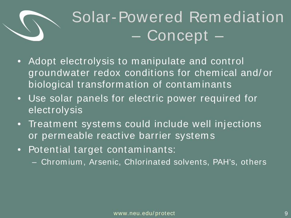
• Adopt electrolysis to manipulate and control groundwater redox conditions for chemical and/or biological transformation of contaminants
• Use solar panels for electric power required for electrolysis
• Treatment systems could include well injections or permeable reactive barrier systems
• Potential target contaminants:– Chromium, Arsenic, Chlorinated solvents, PAH’s, others
9
Solar-Powered Remediation – Concept –

www.neu.edu/protect 10
Ground Surface
_+ _
Porous Iron Electrodes
Porous (Screened) Well
Solar Panel
Contaminated Groundwater Flow
Renewable energy for “sustained” manipulation of groundwater redox conditions
Solar-Powered Remediation – Concept –

www.neu.edu/protect
Basics: Electrolysis
11
Cathode (-)Anode (+)
2H2O - 4e- 4H+ + O2
Production of acid and Oxygen gas
4H2O + 4e- --> 4OH- + 2H2
Production of base and Hydrogen gas
dc source(Solar Panel)
Charge/Mass transfer at the electrodes (Faraday’s Law)
e-
If iron electrode,Fe(0) – 2e- Fe2+ (aq)e-

www.neu.edu/protect 1212
Cathode (-)Anode (+)
2H2O - 4e- 4H+ + O2
Production of acid and Oxygen gas
4H2O + 4e- --> 4OH- + 2H2
Production of base and Hydrogen gas
dc source(Solar Panel)
Charge/Mass transfer at the electrodes (Faraday’s Law)
e-
If iron electrode,Fe(0) – 2e- Fe2+ (aq)e-
Basics: Electrolysis
Soil o
r Mem
bran
e

www.neu.edu/protect
Example Strategy 1 – O2/H2 Production –
• H2O ½ O2 + 2H+ + 2e- (Anode)
• 2H2O + 2e- 2OH- + H2 (Cathode)
• Net reaction in a mixed electrolyte• H2O ½ O2 + H2
• Options:• Collect O2 at the anode and allow H2 to mix with GW
• Collect H2 at the cathode and allow O2 to mix with GW
13

www.neu.edu/protect
Example Strategy 2– Fe Anode Redox –
• Iron Anode: Fe(0) 2e- + Fe2+ (aq)
• Sustainable generation and delivery of Fe(II) to GW
• Chemically reducing conditions develop • Could be used in a mixed or isolated
electrode reactor
14

www.neu.edu/protect 15
Transformation Mechanisms
• Biological– Aerobic: by production of O2 as an electron acceptor;
e.g. PAH– Anaerobic: by production of H2 as an electron donor;
e.g. PCE
• Chemical – Reduction of hexavalent chromium – Oxidation of PAH and BTEX – Alkaline Hydrolysis: transformation of RDX
• Electrochemical– Direct oxidation at the anode or reduction at the cathode

www.neu.edu/protect
EXAMPLE –HEXAVALENT CHROMIUM
16

www.neu.edu/protect
Laboratory Study: Cr(VI) Reduction by Fe electrolysis
• Hypothesis:
– Electrolysis using iron electrodes (anodes and cathodes) will induce Fe(II) (and H2) dominated reducing conditions that can be manipulated for chemical reduction of Cr(IV).
• Justification:
– The reactivity is similar to reduction by ZVI (single electrode redox)
• Advantages:
– The kinetics of electrolysis and consequent redox and transformation can be controlled to optimize (accelerate or limit) the release of Fe(II)/H2 by controlling the electric current density and polarity in a 2 electrode system.
17

www.neu.edu/protect 18
Experimental Setup

www.neu.edu/protect
-200
-150
-100
-50
0
50
100
150
200
250
300
0 5 10 15 20 25
OR
P (
mV
)
Time (hour)
CathodeAnodeMixed Electrolyte
0
2
4
6
8
10
12
0 5 10 15 20 25
pH
Time (hour)
CathodeAnodeMixed Electrolyte
ORP and pH measurements under 1 mA/L using Fe electrodes for cases with separate and mixed electrolytes. Total voltage was on the order of 2 V in the separated and 0.5 V in the mixed electrolytes.
Results – Batch Samples –
19

www.neu.edu/protect20
0
3
6
9
12
15
18
21
0 2 4 6 8 10 12 14 16 18 20 22 24 26Time (hr)
Cr(
VI)
, mg/
L
15mA/L 7.5 mA/L 1.5 mA/L
0.0
0.1
0.2
0.3
0.4
0.5
0.6
0.7
0.8
0.9
1.0
0 50 100 150 200 250 300 350 400 450
It, C/L
C/C
o
15mA/L 7.5 mA/L 1.5 mA/L
Initial Concentration = 20 mg/L
Results – Batch Samples –
20

www.neu.edu/protect
Fe2+2e_
Fe2+2e_
Fe2+2e_
6e_
6H2O
3H2
6OH _
123
33
224
2
83
43
)(OH)(CrFe
OHFeCr
O H CrOFe
+++
++
−++
−+
HOH
OH
+− + 64
6 2
42CrONa
Anode CathodeSolution (Anolyte)
−
+
OHNa
22
3133
332
24
2
20
31
83432
)(OH)Fe(Cr OH -x)Fe ( xCrOHFeCrO H CrOFe
eFeFe
xx-
−++
−++−+
−+
→++
++→++
+→
Cr(VI) Transformation Mechanism
21

www.neu.edu/protect
)( IIFeJ −OHJ
2HJ
L0x
DC
rygeochemist
OHOHOH
rygeochemist
IIFeeIIFeIIFe
iiii
tcJLxxR
tc
JxxR
nRxcv
xcnD
tnc
∂∂
+−−=
=
∂
∂+−=
=
+∂∂
−∂∂
=∂∂
−−−
e0
)()(0)(
2
2
)(
-OHiwhen
)(
Fe(II)iwhen
δ
δ
x
Electrochemical Redoxunder GW Flow
22

www.neu.edu/protect 23
0
0.2
0.4
0.6
0.8
1
1.2
0 50 100 150 200 250 300 350 400 450 500 550 600 650 700 750 800
Time (hr)
C/Co
Port 1
Port 2
Anode
Cathode
Port 3
Port 4
Port 5
Port 6
Port 7
Port 8
Current density of 0.12A/m2 , Electrode spacing of 2.5 cm
No
Current
1 2 3 4 5 6 7 8Port #Flow 8 cm spacing showed similar results
Cr Redox under Flow– Sand Column Tests –

www.neu.edu/protect
0.0
0.1
0.2
0.3
0.4
0.5
0.6
0.7
0.8
0.9
1.0
0 24 48 72 96 120 144 168Time (hr)
C/Co
Port 3
Anode
Cathode
port 6
Port 7
port 8
Effect of Increasing flow rate – Current density of 0.12A/m2
Cr Redox under Flow– Sand Column Tests –
24

www.neu.edu/protect 25
0
0.2
0.4
0.6
0.8
1
1.2
0 50 100 150 200 250 300 350 400 450
Time (hr)
C/Co
Port 1Port 2AnodecathodePort 3Port 4Port 5Port 6Port 7Port 8
No
Current
Flow rate 490 ml/day
Current density of 0.36A/m2
Electrode spacing of 2.5 cm
Cr Redox under Flow– Sand Column Tests –

www.neu.edu/protect
RESEARCH TRANSLATION
26

www.neu.edu/protect
• Assume average groundwater flow rate = 10 cm/day.• Assume Average chromium concentration = 5 mg/l, • Cr flux = 0.5 g/m2.day or 0.01 mole/m2.day. • Required Fe(II) flux [JFe(II)] = 0.03 mole/m2.day• Required electric current density (I=2JFe(II)F/0.75) = 0.09 A/m2. • 50W solar panel (few $100) with 3 Amps (20 Volt) would cover
a cross sectional area of more than 30 m2 of flowing groundwater.
• Assumptions: – 3 moles of Fe(II) are required per 1 mole of Cr(VI).
– 75% electrolysis efficiency
27
Practical Issues:How Much Energy - Example?

www.neu.edu/protect
Potential Challenges
• Precipitation and changes in hydraulic conductivity– Function of electric current/flow rate, GW chemistry
• Passivation:– Less likely, but use polarity reversal if it occurs
• pH changes in GW– Function of electric current/flow rate, GW chemistry
• Delivery to contaminated zones
28
Process design is critical

www.neu.edu/protect 29
Ground Surface
_+ _
Porous Iron Electrodes
Porous (Screened) Well
Solar Panel
Contaminated Groundwater Flow
Ground Surface
_ +_
Porous Iron Electrodes
Porous (Screened) Well
Fe(II) Front
H2 & OH-
Front
Solar Panel
Contaminated Groundwater Flow
Implementation Strategies – Examples –

www.neu.edu/protect 30
Bae et al., 1995 McCarty et al., 1998; Goltz et al., 2009
Implementation Strategies – Examples –

www.neu.edu/protect
CURRENT EFFORT
31

www.neu.edu/protect
PI/Co-Director: Akram N. Alshawabkeh, Professor, Civil and Environmental Eng., NUCo-Director: José F. Cordero, Dean, Graduate School of Public Health, UPR-MC
http://www.northeastern.edu/protect

www.neu.edu/protect
PROTECT Focus
• Role of exposure to contamination on preterm birth
• Contamination in Puerto Rico (14 Superfund site + 2 Proposed)
• karst aquifers • Target Contaminants: Chlorinated
Solvents and Phthalates
33

www.neu.edu/protect
PROTECT Project 5Alshawabkeh, Padilla, Podlaha, Vesper
• Goal: Developing green remediation technologies based on conversion of solar energy into electrochemical redox in groundwater
• Focus on chlorinated solvents in karst aquifers• Proposed transformation pathways:
34

www.neu.edu/protect
SUMMARY AND ACKNOWLEDGMENT
35

www.neu.edu/protect
Summary
• Solar energy conversion into electrochemical redox in groundwater can be a green and sustainable remediation technology
• Oxidizing or reducing groundwater conditions can be engineered
• Conditions can be developed for chemical, biological and/or electrochemical transformation
• Fe anodes would lead to reducing conditions causing reduction and immobilization of chromium
• Transformation of chlorinated solvents by iron electrodes is being evaluated in karst aquifers
36

www.neu.edu/protect
Acknowledgment
• PRoTECT Team and Advisory Committees• CenSSIS (Center for Subsurface Sensing
and Imaging Systems) Team• NIEHS SRP Award Number P42ES017198• NIEHS SRP Team • Post-docs, Students and Teachers
– Hussam Sarahney, David Gent, Xuhui Mao, Ali Ciblak, Sara Barbuto, Samantha Kendrick, Susan Agger, Jessica Quinn, Mohammad Amiri, Reza Ghasemizadeh, Naji Kasem, HatimFedllalah, Xingzhi Wu

www.neu.edu/protect
PROTECT Team
38
Tom Ferdi Akram José Raul John Sangchul
Rita Braulio Roger Ingrid Mariah Kristin Michael Dave