The Originator of the Red Dot Sight - Micro T-2™ …...2.2 Install Aimpoint® Micro T-2 on a...
12
Micro T-2™ User manual
Transcript of The Originator of the Red Dot Sight - Micro T-2™ …...2.2 Install Aimpoint® Micro T-2 on a...

Micro T-2™User manual

1 PRESENTATION Aimpoint® red dot sights are designed for the ”two eyes open” method which greatly enhances situational awareness and target acquisition. Thanks to the optical design the red dot follows the movement of the user’s eye while remaining fixed on target, eliminating any need for centering.
1.1 Technical specification
Optical systemMagnifiction 1XEye relief UnlimitedClear aperture 18 mmNVD2 compatible YesOptical coating Anti-reflex (AR) coatingAdjustments 1 click = 10 mm at 80 m =
13 mm at 100 m = 0.5 in at 100 ydsAdjustment range (windage and elevation)
±1 m at 100 m ±1 yds at 100 yds
Dot size 2 MOA1
Dot intensity settings
12 settings manually adjusted with switch. Setting 1-4 for use with NVD and setting 5-12 for use in daylight.
Dot color Red (655 nm ± 10 nm)

Signature No forward optical signature from the dot beyond 10 meters
Power sourceBattery type One CR2032 Lithium batteryBattery life3 More than 5 years of use
at setting 8. More than 10 years of use at NVD-setting (1-4).
Size (L × W × H)Sight 68 mm × 41 mm × 36 mm
2.7 in × 1.6 in × 1.4 inConfiguration 79 mm × 41 mm × 48 mm
3.1 in × 1.6 in × 1.9 in
WeightSight (incl. battery) 96 g / 3.4 ozConfiguration 135 g / 4.8 oz
Height of optical axisConfiguration (no spacer) 20 mm / 0.8 in (measured from
top surface of picatinny rail)
Mechanical interfaceConfiguration MIL-STD 1913 Rail system
(Picatinny rail)

MaterialsSight and mount High strength aluminum, hard
anodized, black to dark gray, non-glare finish
Lens covers Thermoplastic elastomer, black, non-glare finish
Environmental specificationTemperature range (operation)
-45 °C to +71 °C -49 °F to +160 °F
Temperature range (storage)
-51 °C to +71 °C -60 °F to +160 °F
Water resistance 25 m / 80 ft.Chemical resistance Withstands occasional
contamination by weapons cleaners, lubricants, oil or insect repellants
1 MOA: Minute Of Angle, 1 MOA ≈ 30 mm at 100 m or ≈ 1 in at 100 yds2 NVD: Night Vision Device3 Battery life: Values valid at room temperature for a quality battery

1.2 Overview (configuration)
5
61
7
8
9
13
14
4
3
2
10
11
12
B
C
A
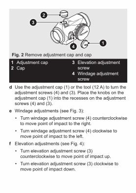
1 Adjustment cap2 Cap3 Elevation adjustment
screw 4 Windage adjustment
screw5 Battery cap6 Battery (CR2032)7 Intensity switch
8 Base9 Screws (for base)10 Rear flip-up lens cover11 Front flip-up lens cover12 Tool (ABC)13 Locking bar14 Screw
Fig. 1 Overview (configuration)

2 OPERATIONWARNING: Ensure the weapon is not loaded and the safety selector is in the ”safe” position before attempting to install, remove or perform maintenance.
2.1 Install batterya Remove the battery cap (5) using the tool (12 B). b Insert battery (6) with positive end (+) toward battery
cap (5) as can be seen in Fig. 1.
CAUTION: Check that the o-ring is in good condition and in position to ensure there is no water leakage into the battery compartment.
c Turn to the intensity switch (7) to intensity setting 12 (max.) and tighten the battery cap (5) with the tool (12 B). When resistance is encountered, proceed to tighten until the battery cap (5) comes to a stop.
d Verify that the red dot is visible and that there is zero gap between the battery cap (5) and the battery compartment.
NOTE: For storage of the sight, remove the battery.

2.2 Install Aimpoint® Micro T-2 on a weaponIf the sight is equipped with the mount shown in Fig. 1, follow the described procedure. For installation with other mounts, see accompanying instruction.
a Loosen the screw (14) using the tool (12 C), and clamp the locking bar (13) around the Picatinny rail.
b With the screw (14) (recoil stop) positioned in a groove of the Picatinny rail, push the sight forward (towards muzzle) and tighten the screw (14) using the tool (12 C)
c Tighten the screw (14) until a light resistance is encountered. Proceed with another 1/4 to 1/2 turn until fully tightened (2 Nm / 1.5 ft·lb).
CAUTION: Do not overtighten.
2.3 ZeroingCAUTION: Do not continue to adjust windage and elevation screws (3) and (4) if you encounter resistance.
a Open lens covers (10) and (11).b Adjust the intensity (7) to a comfortable setting for the
red dot to contrast against the target.c Remove the adjustment cap (1) and the cap (2) to
access the windage adjustment screw (4) and the elevation adjustment screw (3). See Fig. 2.
4
32
1
1 Adjustment cap2 Cap
3 Elevation adjustment screw
4 Windage adjustment screw
Fig. 2 Remove adjustment cap and cap
d Use the adjustment cap (1) or the tool (12 A) to turn the adjustment screws (4) and (3). Place the knobs on the adjustment cap (1) into the recesses on the adjustment screws (4) and (3).
e Windage adjustments (see Fig. 3):• Turn windage adjustment screw (4) counterclockwise
to move point of impact to the right.• Turn windage adjustment screw (4) clockwise to
move point of impact to the left.f Elevation adjustments (see Fig. 4):
• Turn elevation adjustment screw (3) counterclockwise to move point of impact up.
• Turn elevation adjustment screw (3) clockwise to move point of impact down.

NOTE: Each click of the adjustment screws (4) and (3) corresponds to a 13 mm movement of the point of impact at 100 m or 0.5 in at 100 yds.
Fig. 3 Windage adjustments
Fig. 4 Elevation adjustments
g Confirm zeroing by firing at least three shots at a zeroing target. Check points of impact to confirm accuracy and repeat zeroing procedure if required.
h After initial firing, ensure the sight is securely installed on the weapon.
3 EXTREME CONDITIONS• Extreme heat (moist or dry): no special procedures
required.• Extreme cold: extreme cold might shorten battery life.
The intensity switch (7) can be more difficult to operate than at normal temperatures.
• Salt air: no special procedures required.• Sea spray, water, mud, snow: ensure the battery cap (5) and
the adjustment cap (1) and cap (2) are tightened. Tighten the adjustment cap (1), the cap (2) and the battery cap (5) by
hand and by the use of the tool (12 B). Keep lens covers (10) and (11) closed when the sight is not being used. Clean lenses and wipe the sight dry after exposure.
• Dust storms and sand storms: keep lens covers (10) and (11) closed when the sight is not being used.
• High altitudes: no special procedures required.
CAUTION: Never clean the lenses with fingers. Use lens paper/cloth. If lens paper/cloth is not available:
• To clear away debris (sand, grass etc.): blow away the dirt or rinse with clear water.
• To clean lenses: fog the lenses or rinse with clear water and clean them with a soft piece of cloth.
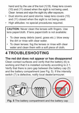
4 TROUBLESHOOTINGThe red dot does not appear or has disappearedClean contact surfaces and verify that the battery (6) is working and that it is installed correctly according to 2.1. Verify that there is zero gap between the battery cap (5) and the battery compartment (see Fig. 5). If the intensity switch (7) is defective, notify local dealer/armourer.
Fig. 5 The battery compartment and the battery cap

The sight is impossible to zeroIf an adjustment screw (3) or (4) is at its limit, check the alignment of mount and barrel. If point of impact is moving, check the stability of mount and weapon rail (or carry handle)
The front lens of the sight is tilted, has the sight been damaged?No. The optical system is designed for the front lens to be mounted in this way.
5 MOUNT INSTALLATIONTo avoid damage to the sight and for proper assembly of the base (8) onto the sight, the original screws (9) (M3, 4 pcs) must be tightened by hand and with the tool (12 C).
a
CAUTION: Do not use thread locking fluid as it may damage the thread inserts of the sight.
a Place the sight upside down in your hand.b Press the base (8) against the sight and verify there is
no gap.c Tighten the screws (9) in a crosswise pattern. Tighten
until resistance is encountered. Proceed with another 1/4 to 1/2 turn until fully tightened (1.35 Nm / 1.0 ft·lb).
CAUTION: Do not overtighten.

© 2014, 2017 Aimpoint AB. [13939-5]
Aimpoint ABJägershillgatan 15SE- 213 75 Malmö, SwedenPhone: +46 (0)40 671 50 20Fax: +46 (0)40 21 92 38e-mail: [email protected]
WWW.AIMPOINT.COM
Aimpoint Inc.7309 Gateway CourtManassas, VA 20109, USAPhone: +1 703-263-9795Fax: +1 703-263-9463e-mail: [email protected]


![PUBLICACIÓN PROFESIONAL POLICIAL - … · TACTICAL ONLINE [5] JULIO 2011 Subfusil B&T APC9 con visor Aimpoint Micro T-1 Subfusil B&T APC-45 con visor Aimpoint Micro T-1 Subfusil](https://static.fdocuments.net/doc/165x107/5b797ad17f8b9a02268dab7a/publicacion-profesional-policial-tactical-online-5-julio-2011-subfusil.jpg)