The Neighbourhood Planning and Design Guide...“everyone has a right of access to basic water...
108
Section K Sanitation The Neighbourhood Planning and Design Guide Part II Planning and design guidelines
Transcript of The Neighbourhood Planning and Design Guide...“everyone has a right of access to basic water...

Section KSanitation
The Neighbourhood Planning and Design Guide
Part II
Planning and design guidelines

PART I: SETTING THE SCENE A The human settlements context
B A vision for human settlements
C Purpose, nature and scope of this Guide
D How to use this Guide
E Working together
PART II: PLANNING AND DESIGN GUIDELINES F Neighbourhood layout and structure
G Public open space
H Housing and social facilities
I Transportation and road pavements
J Water supply
K Sanitation
L Stormwater
M Solid waste management
N Electrical energy
O Cross-cutting issues
Planning and designing safe communities
Universal design
More detailed information is provided about the issue under discussion
Important considerations to be aware of are highlighted
Relevant content from a complementing resource is presented
Developed byDepartment of Human SettlementsPublished by the South African Government
ISBN: 978-0-6399283-2-6
© 2019
Version 1.1. Printed January 2019
Symbols at text boxes

Section KSanitation
The Neighbourhood Planning and Design Guide

Table of contents
K.1 Outline of this section ............................................................................................................................. 4 K.1.1 Purpose ...................................................................................................................................................... 4 K.1.2 Content and structure ................................................................................................................................ 4
K.2 Universal considerations ........................................................................................................................ 6 K.2.1 The regulatory environment ...................................................................................................................... 6 K.2.2 Key objectives ............................................................................................................................................ 9 K.2.3 Approaches and concepts ....................................................................................................................... 9 K.2.3.1 Water Sensitive Urban Design/ Water Sensitive Design ................................................ 9 K.2.3.2 Basic sanitation facility and basic sanitation service ......................................................11 K.2.3.3 Sustainabe sanitation service ...........................................................................................11 K.2.3.4 Appropriateness of sanitation and wastewater services ............................................... 12 K.2.3.5 Infrastructure asset management ..................................................................................... 12 K.2.4 The implementation context .................................................................................................................... 13 K.2.4.1 The type of development .................................................................................................. 13 K.2.4.2 The setting of the development ........................................................................................ 14
K.3 Planning considerations ........................................................................................................................16 K.3.1 Characteristics of the proposed development ...................................................................................... 16 K.3.1.1 The nature of the proposed development ....................................................................... 16 K.3.1.2 The residents of the area to be developed ..................................................................... 16 K.3.2 Characteristics of the existing environment ........................................................................................... 18 K.3.2.1 The physical location of the proposed development ..................................................... 18 K.3.2.2 Available engineering infrastructure ............................................................................... 19 K.3.2.3 Existing socio-economic features ....................................................................................20 K.3.3 Sanitation and wastewater options ....................................................................................................... 21 K.3.3.1 Sanitation facilities ........................................................................................................... 21 K.3.3.2 Sewage treatment ............................................................................................................23 K.3.3.3 End use/ Disposal after treatment .................................................................................26 K.3.3.4 Greywater ........................................................................................................................27
K.4 Design considerations .......................................................................................................................... 28 K.4.1 Design of collection, storage/treatment and conveyance infrastructure ...........................................28 K.4.1.1 Ventilated Improved Pit toilet ...........................................................................................28 K.4.1.2 Composting toilet .............................................................................................................. 31 K.4.1.3 Urine-diverting dry toilet ..................................................................................................33 K.4.1.4 Pour-flush toilet..................................................................................................................34 K.4.1.5 Aqua privy.........................................................................................................................34 K.4.1.6 Septic leach field system ..................................................................................................35
SanitationKThe Neighbourhood Planning and Design Guide
K.1

K.4.1.7 Anaerobic baffled reactor ...............................................................................................36 K.4.1.8 Anaerobic digester/ Biogas reactor ...............................................................................36 K.4.1.9 Vacuum sewer system .......................................................................................................36 K.4.1.10 Small-bore sewer system .................................................................................................37 K.4.1.11 Simplified/ shallow sewer system ...................................................................................38 K.4.1.12 Waterborne sanitation .....................................................................................................38 K.4.2 Sewage flow calculation ........................................................................................................................39 K.4.2.1 Regular flow ...................................................................................................................... 41 K.4.2.2 Groundwater infiltration ...................................................................................................55 K.4.2.3 Allowance for stormwater ingress ...................................................................................57 K.4.2.4 Design flow calculation ....................................................................................................57 K.4.3 Hydraulic design guidelines for waterborne sanitation systems..........................................................58 K.4.3.1 Hydraulic spare capacity calculation .............................................................................58 K.4.3.2 Velocity calculation ..........................................................................................................60 K.4.3.3 Gravity sewer system .......................................................................................................62 K.4.3.4 Pumped sewer system ......................................................................................................63 K.4.4 General design guidelines for waterborne sanitation systems ............................................................68 K.4.4.1 Sewer pipes ......................................................................................................................68 K.4.4.2 Manholes ..........................................................................................................................72 K.4.4.3 Sewer connections ........................................................................................................... 76 K.4.4.4 Pump stations ....................................................................................................................79 K.4.4.5 Syphons ............................................................................................................................. 81 K.4.4.6 Special structures ..............................................................................................................83 K.4.5 Design of wastewater treatment infrastructure ......................................................................................84 K.4.5.1 Activated sludge and biofiltration treatment systems .....................................................84 K.4.5.2 Pond systems .....................................................................................................................84 K.4.5.3 Package purification plants .............................................................................................85 K.4.6 Design of greywater management systems ...........................................................................................85 K.4.6.1 Volumes .............................................................................................................................85 K.4.6.2 Disposal .............................................................................................................................85 K.4.7 Design of sludge disposal infrastructure ................................................................................................86 K.4.7.1 Disposal of sludge from on-site sanitation systems ........................................................86 K.4.7.2 Composition of pit or vault contents ................................................................................87 K.4.7.3 Methods of emptying pits ................................................................................................87 K.4.7.4 Disposal of sludge on a large scale ................................................................................87 K.4.8 Materials ..................................................................................................................................................88 K.4.8.1 Pipes and joints .................................................................................................................88 K.4.8.2 Manholes ..........................................................................................................................90 K.4.8.3 Bedding and backfill ........................................................................................................ 91
JSanitationThe Neighbourhood Planning and Design Guide
K
K.2

K.4.8.4 Pump stations .................................................................................................................... 91 K.4.8.5 Concrete ............................................................................................................................ 91 K.4.8.6 Structural steelwork .......................................................................................................... 91 K.4.8.7 Electrical installations ....................................................................................................... 91 K.4.9 Upgrading of existing sanitation systems .............................................................................................. 91 K.4.9.1 Upgrading chemical toilets .............................................................................................92 K.4.9.2 Upgrading unventilated pit toilets ...................................................................................92 K.4.9.3 Upgrading ventilated improved pit toilets ......................................................................92 K.4.9.4 Upgrading ventilated vault toilets ....................................................................................92 K.9.4.5 Upgrading ventilated improved double pit toilets .........................................................92 K.4.9.6 Upgrading conservancy tank systems ............................................................................92 K.4.9.7 Upgrading septic tank systems ........................................................................................93 K.4.9.8 Upgrading aqua privies ...................................................................................................93 K.4.9.9 Upgrading settled sewage systems .................................................................................93
Glossary, acronyms, abbreviations ..................................................................................................... 94 Endnotes .............................................................................................................................................. 97
SanitationKThe Neighbourhood Planning and Design Guide
K.3

K.4
SanitationK.1Outline of this section
K.1 Outline of this section
K.1.1 Purpose
Settlements (and neighbourhoods as the ‘building blocks’ of settlements) are integrated systems in which various components are interconnected, and this section highlights the role of sanitation (including wastewater) in this system. The aspects addressed in this section play an essential role in achieving the vision for human settlements outlined in Section B and relate in particular to Section J which deals with water supply and Section L which deals with stormwater.
K.1.2 Content and structure
This section (Section K) is structured to support effective decision-making related to the provision of sanitation. The decision-making framework is outlined in Figure K.1, and the structure of this section is briefly described below.
Universal considerations
General aspects that should be taken into consideration when making higher level decisions regarding the provision of sanitation are highlighted, including the following:
• The regulatory environment, including key legislation, policies, frameworks and strategies• The key objectives that should be achieved as a result of the application of the guidelines provided• Local or international approaches, mechanisms, concepts and current trends that could possibly be utilised to
achieve the key objectives• Contextual factors specific to the development project to be implemented such as the development type and
setting
Planning considerations
Factors to consider when making more detailed decisions regarding the provision of sanitation are outlined, including the following:
• The characteristics of the development, including the nature of the proposed neighbourhood, the anticipated number of residents and specific features that would have to be incorporated or requirements that would have to be met
• The existing features of the site and immediate surroundings (built and natural environment) as determined by the physical location of the proposed development
• Options related to the provision of sanitation that are available for consideration
Design considerations
Guidelines to assist with the design of sanitation systems and infrastructure.

K.5
Sanitation
Glossary, acronyms, abbreviations
A glossary, a list of acronyms and abbreviations, and endnotes (containing sources of information, explanatory comments, etc.) are provided at the end of Section K.
K.1
Figure K.1: A framework to assist with planning and design decisions
The regulatoryenvironment
Legislation
Frameworks
Strategies
Regulations
Norms
Standards
Keyobjectives
(i)
(ii)
(iii)
(iv)
(v)
(vi)
(?)
PLANNING CONSIDERATIONS
DESIGN CONSIDERATIONS
Options
The implementation contextType of project
Greenfield l Brownfield l Informal settlement upgrading
Setting of the developmentUrban l Rural l Peri-urban
UNIVERSAL CONSIDERATIONS
Approaches and concepts
Approaches
Concepts
Trends
Mechanisms
Characteristicsof the
proposeddevelopment
Characteristicsof the
existingenvironment
1 2 3 4 ?
Outline of this section

K.6
SanitationK.2Universal considerations
K.2 Universal considerations
K.2.1 The regulatory environment
A range of legislation, policies and strategies guide the provision of sanitation and wastewater infrastructure and services to South African settlements. Some of these are listed below. Since they are not discussed in detail, it is vital to consult the relevant documents before commencing with any development. (Also see Section D.1.)
All building and construction work in South Africa is governed by the National Building Regulations and Building Standards Act, 1977. Always refer to SANS 10400 - The application of the National Building Regulations available from the South African Bureau of Standards (SABS).1 Municipalities may have additional guidelines, regulations and by-laws that may be applicable.
The Department of Water and Sanitation (DWS) is the custodian of the country’s water resources. Its legislative mandate seeks to ensure that the country’s water resources are protected, managed, used, developed, conserved and controlled in a responsible manner, which includes the proper provision of sanitation and wastewater systems.
The National Water Services Act
The legislation that regulates the provision of sanitation and wastewater management in South Africa is mainly the National Water Services Act (NWSA), 1997, supported by the National Water Act, 1998. The NWSA governs the provision of universal access to sanitation and wastewater services to users. Section 3 of the act states that “everyone has a right of access to basic water supply and sanitation”. Basic sanitation is defined as “the prescribed minimum standard of services necessary for the safe, hygienic and adequate collection, removal, disposal or purification of human excreta, domestic wastewater and sewage from households, including informal households”. Section 3 also states that services authorities must take reasonable measures to realise this right in their Water Services Development Plans, and they must give preference to basic water supply and basic sanitation facilities.
The National Water Act
The National Water Act (NWA),1998 provides for the regulation of the quality of effluent that may be discharged by a Wastewater Treatment Works (WWTW) into receiving waters. When a WWTW receives more sewage than the works can treat or store temporarily, partially treated or untreated sewage is released directly into receiving waters, which is illegal.
National Sanitation Policy
The National Sanitation Policy of 2016 seeks to address the identified existing sanitation challenges, gaps and burning issues to achieve universal access by 2030. It provides policy positions to address the identified policy gaps and challenges, as well as the country’s latest national and international development imperatives. Its focus is to ensure and strengthen integrated sanitation services, institutional arrangements for sanitation services, participation in sanitation services, capacity and resources for sanitation services delivery, financial effectiveness and efficient sanitation services, sustainable sanitation provision in the country, and regulation of sanitation services.

K.7
Sanitation
The key objectives for sanitation and wastewater, as set out in the National Sanitation Policy2, are the following:
• To realise the right of access to basic sanitation – a recognised constitutional responsibility of the national sphere of government, with local government mandated to take reasonable measures to realise this right.
• To give priority to hygiene as well as end-user education in sanitation service provision – hygiene education should be continuous, based on needs, and address all geographic areas in the country. Further, hygiene education should make users aware of their sanitation rights and responsibilities and incorporate water conservation and demand management.
• To give priority to basic sanitation services for vulnerable people and unserved households – in recognition of the special requirements for these individuals and households to gain access to sanitation facilities.
• To provide people-centred and demand-driven sanitation services – sanitation services must recognise sanitation as a right, consider users’ expectations and needs in planning and implementation, and devolve decision making and control to the lowest possible levels of accountability. Conversely, the policy recognises that “there is a reciprocal obligation on communities to accept responsibility for their development and governance, with the assistance of the State”.
• To reduce pollution through the polluter-pays concept – any reduction of receiving water quality should have a value assigned to it. As such, water quality management shall “include the use of economic incentives and penalties to reduce pollution…”, thus placing an obligation on sanitation services to be implemented to reduce pollution.
• To promote the user-pays concept – implementation, regulation and enforcement of the user-pays concept are central to sustainable sanitation service provision. Therefore, the “beneficiaries of the water management system shall contribute to the cost of its establishment and maintenance on an equitable basis”.
• To promote the economic value of sanitation – “the public and economic benefit of improved sanitation must be recognised and valued”. This should be reflected in how the sanitation by-products are approached and handled, and should recognise the impact of sanitation services on the water scarcity situation in the country.
• To ensure integrated development – sanitation services should be provided in an integrated manner together with other basic services to maximise the public health and economic benefits.
• To ensure equitable regional allocation of development resources – “the limited national resources available to support the provision of basic services should be equitably distributed among regions, taking account of population and level of development”.
• To promote the value of sanitation by-products – the recognition of the full value of sanitation by-products, with reinvestment into the system, could foster increased investments and generate efficiency gains.
• To give priority to operation and maintenance – the planning of capital expenditure for sanitation services should take into account the related operation and maintenance costs. Thus, sufficient resources must be allocated for the adequate maintenance of infrastructure and related systems.
• To ensure integrated waste management – the provision of sanitation services should recognise all the various forms of waste emanating from the household. These must be handled (stored, removed and managed) in an integrated and coordinated manner.
National Norms and Standards for Domestic Water and Sanitation Services
The National Norms and Standards for Domestic Water and Sanitation Services of 2017 particularly draw on the principles of universal access, human dignity, user participation, service standards, redress, and value for money. The principles of sustainability, affordability, effectiveness, efficiency and appropriateness should be upheld in supplying water to a community. Cognisance is taken of the water scarcity context of the country and as such, reduction, reuse and recycling are common themes that underpin the norms and standards. The effectiveness of the services towards the protection of public health and the greater economic development agenda of the country also receive attention.
K.2 Universal considerations

K.8
SanitationK.2
The Second National Water Resource Strategy
The water resource protection theme of the Second National Water Resource Strategy (NWRS2) of 2013 emphasises the need to protect freshwater ecosystems that are under threat because of pollution. Reuse of water is becoming more acceptable and feasible because of increasing water shortages, improved purification technology and decreasing treatment costs, taking into consideration public health and safety, as well as water quality management and control.
The National Water and Sanitation Master Plan
The National Water and Sanitation Master Plan (NW&SMP) of 2017 introduces a new paradigm that will guide the South African water sector, led by the DWS and supported by local government and other sector partners, towards the urgent execution of tangible actions that will make a real impact on the supply and use of water and sanitation. The NW&SMP forms part of a suite of initiatives led by the DWS in conjunction with other government departments and agencies, the private sector and civil society, to aim for a water-secure future with reliable water and sanitation services for all, and to contribute to meeting national development objectives.
The National Framework for Sustainable Development
The National Framework for Sustainable Development (NFSD) of the Department of Environmental Affairs (DEA) emphasises a cyclical and systems approach to achieving sustainable development through efficient and sustainable use of natural resources; socio-economic systems embedded within, and dependent upon, ecosystems; and meeting basic human needs to ensure resources necessary for long-term survival are not destroyed for short-term gain.
The National Environmental Management Act
The National Environmental Management Act (NEMA),1998 is the framework legislation for environmental management in South Africa. Any new development should adhere to the national environmental management principles included in this act and comply with the environmental management regulations. Regulations published in terms of NEMA list activities for which Environmental Impact Assessments (EIAs) are required to evaluate the impact of human actions on the receiving environment.
The National Environmental Management: Integrated Coastal Management Act
The National Environmental Management: Integrated Coastal Management Act (ICM Act), 2008 regulates the conservation and sustainable management of South Africa’s coastal environment. Under the ICM Act, anyone wishing to discharge effluent from a land-based source into coastal waters must apply to the DEA for a coastal waters discharge permit.
Water Services Development Plans
Central to providing sanitation and wastewater services to a neighbourhood is the Water Services Development Plan (WSDP) of the relevant Water Services Authority (WSA), which is required in terms of the Water Services Act. The WSDP defines the minimum as well as the desired level of services for communities, which must be adhered to by a Water Services Provider (WSP) in its area of jurisdiction. It describes the current and future arrangements for service provision in an area.
Universal considerations

K.9
Sanitation
K.2.2 Key objectives
The water sector strives to establish water sensitive and waterwise settlements in providing universal access to safe drinking water and adequate sanitation. Objectives related to the provision of sanitation and wastewater infrastructure and services have been formulated in a range of South African policy and planning publications, and the planning and design assistance included in this Guide aims to support these.
Poor sanitation systems and inappropriate drainage/treatment of wastewater almost always lead to the pollution of local water sources with pathogens, rendering them unsafe for human use. It is fundamental to sustainable development that local water sources be protected from contamination. It is also vital that due care is taken to minimise the negative downstream effects of wastewater treatment and/or disposal. To achieve the objectives of the 2016 National Sanitation Policy (see Section K.2.1), a sanitation service must meet the following requirements:
• Sufficient: The water supply and sanitation facility for each person must be continuous and sufficient for personal and domestic uses. These uses ordinarily include drinking, personal sanitation, washing of clothes, food preparation and personal and household hygiene. According to the World Health Organization (WHO), between 50 and 100 litres of water per person per day is needed to ensure that most basic needs are met and few health concerns arise.
• Safe: Everyone is entitled to safe and adequate sanitation. Facilities must be situated where physical security can be safeguarded. This means toilets must be available for use at all times of the day or night, hygienic, constructed to prevent collapse, and wastewater and excreta must be safely disposed of. Services must ensure privacy and water points should be positioned to enable use for personal hygiene, including menstrual hygiene. Ensuring safe sanitation also requires substantial hygiene education and promotion.
• Acceptable: All water and sanitation facilities and services must be culturally appropriate and sensitive to gender, life-cycle and privacy requirements. Sanitation should be culturally acceptable and provided in a non-discriminatory manner, including for vulnerable and marginalised groups. This includes addressing public toilet construction issues such as separate female and male toilets to ensure privacy and dignity.
• Physically accessible: Everyone has the right to water and sanitation services that are physically accessible within or near their household, workplace, and education or health institutions. Relatively small adjustments to water and sanitation services can ensure that the needs of the disabled, elderly, women and children are not overlooked, thus improving dignity, health and overall quality for all.
• Affordable: Water and sanitation facilities and services must be available and affordable for everyone, even the poorest. The costs for water and sanitation services should not exceed 5% of a household’s income, meaning services must not affect people’s capacity to acquire other essential goods and services, including food, housing, health services and education.3
K.2.3 Approaches and concepts
This section briefly summarises possible approaches, strategies and mechanisms, as well as local or international concepts, ideas and trends that could be considered to achieve the objectives discussed in Section K.2.2.
K.2.3.1 Water Sensitive Urban Design / Water Sensitive Design
Water Sensitive Urban Design (WSUD), an approach to urban water management that originated in Australia, is an approach aimed at managing the urban water cycle more sustainably to improve water security.4 Within the South African context, WSUD is also referred to as Water Sensitive Design (WSD) to acknowledge the fact that the approach could be applied to settlements in general, not only to those in an urban setting.5 The basic premise
K.2 Universal considerations

K.10
Sanitation
of WSUD/WSD is that water is a scarce and valuable resource, and therefore it needs to be managed wisely and with due care (sensitively). This approach encompasses all aspects of the water cycle and integrates urban design with the provision of infrastructure for water supply, sanitation, wastewater, stormwater and groundwater.The purpose of WSUD/WSD is to reduce the negative impact of urban development on the environment and to enhance the sustainability of water. The intention is to, as far as possible, mimic the natural process of maintaining the water balance when planning and designing a neighbourhood or settlement (see Figure K.2).
Figure K.2: The water cycle under different conditions
RunoffRunoff
Evapotranspiration
Evapotranspiration
Evapotranspiration
Evapotranspiration
GroundwaterGroundwater Groundwater
Precipitation
Evapotranspiration
LessEvapotranspiration
Potable water imported
Wastewater discharge
Less GroundwaterContaminatedrunoff Rivers and other water bodies
exposed to contamination
Contaminatedrunoff
Precipitation
IncreasedEvapotranspiration
More groundwater
Less potable water imported
Wastewater reused Less
wastewater discharge
Contaminated runoffTreatment
Better quality runoffStormwater reuse
Contaminatedrunoff
Precipitation
Rivers and other water bodies
Rivers and other water bodies
The natural water cycle
The urban water cycle
The urban water cycle with WSUD
The natural process (water cycle) involves, amongst others, precipitation, evapotranspiration, runoff and infiltration. However, in a built-up area, other components are added to the process. In addition to precipitation, potable water is imported into the area, wastewater is generated that needs to be discharged somewhere, and evapotranspiration is inhibited. Furthermore, because a substantial part of the area is covered with hard surfaces (buildings, streets, paving etc.), infiltration of water into the earth is reduced while the volume of (poor quality) runoff increases.
K.2Universal considerations

K.11
Sanitation
WSUD/WSD aims to reduce the adverse effects of the built environment on the water balance and to create settlements that preserve the natural water cycle. Strategies or interventions that could be implemented include the following:6
• Sustainable Drainage Systems (SuDS). This is an approach to managing stormwater runoff that aims to reduce downstream flooding, allow infiltration into the ground, minimise pollution, improve the quality of stormwater, reduce pollution in water bodies, and enhance biodiversity. Rather than merely collecting and discarding stormwater through a system of pipes and culverts, this approach recognises that stormwater could be a resource. SuDS involve a network of techniques aimed at controlling velocity and removing pollutants as runoff flows through the system. This involves mechanisms and methods such as rainwater harvesting, green roofs, permeable pavements, soakaways, swales, infiltration trenches, bio-retention areas, detention ponds, retention ponds, wetlands etc. These interventions can form a natural part of open spaces in a settlement and contribute to the quality of the environment and the character of a neighbourhood.7
• Appropriate sanitation and wastewater systems. Technologies that reduce water use, allow for the use of treated wastewater or recycled water, and minimise wastewater could contribute significantly to the effective and efficient utilisation of water resources in a settlement.
• Groundwater management. Groundwater should be regarded as a resource, and therefore aquifers should be conserved and protected from contamination and artificial recharge options should be considered where appropriate.
• Sustainable water supply. Various aspects should be considered to improve efficient water use and reduce the demand for potable water, including water conservation, water demand management, addressing water losses, and exploiting alternative water sources (e.g. rainwater, stormwater, wastewater and groundwater).
WSUD/WSD requires a multi-disciplined, holistic approach to neighbourhood and settlement planning and design. Various sections of this guide relate directly to this approach, in particular Section F (Neighbourhood layout and structure), Section G (Public open space), Section I (Transportation and road pavements), Section J (Water supply), and Section L (Stormwater).
K.2.3.2 Basic sanitation facility and basic sanitation service
A basic sanitation facility is described in the 2016 National Sanitation Policy as “the infrastructure necessary to provide an appropriate sanitation facility which considers natural (water; land; topography) resource constraints, is safe including for children, reliable, private, socially acceptable, maintainable locally, protected from the weather and ventilated, keeps smells to the minimum, is easy to keep clean, minimises the risk of the spread of sanitation-related diseases by facilitating the appropriate control of disease carrying flies and pests, facilitates hand washing and enables safe and appropriate treatment and/or removal of human waste and wastewater in an environmentally sound manner”, and a basic sanitation service is “the provision of an appropriate basic sanitation facility which is environmental sustainable, easily accessible to a household, the sustainable operation of the facility, including the safe removal of human waste, greywater and wastewater from the premises where this is appropriate and necessary, and the communication and local monitoring of good sanitation, hygiene and related practices”.8
K.2.3.3 Sustainable sanitation service
Sustainability of a service is achieved when users want and accept the level of service provided, can pay for it, and the skills are available locally to operate, repair, maintain and upgrade the system. Different service levels come at different costs and they require different activities, capacity and capabilities of a service provider, different systems for operation and maintenance, and different rules for users. These need to be taken into account when
K.2 Universal considerations

K.12
Sanitation
planning sanitation services and determining service levels in the diverse areas of the country. A sanitation service is sustainable when it complies with the following requirements:
• Water sources are not polluted • It provides the services for which it was planned • It demonstrates a cost-effective use of resources that can be replicated • It functions properly and continuously, and is used over a prolonged period, according to the designed life
cycle of the infrastructure and equipment• The management of the sanitation service involves the users, is sensitive to gender issues, establishes partnerships
with local authorities, and involves the private sector as required • The operational, maintenance, rehabilitation, replacement and administrative costs are covered at the local
level through user tariffs, or through alternative sustainable financial mechanisms • It can be operated and maintained at the local level with limited, but feasible, external support (e.g. technical
assistance, training and monitoring)• It has no harmful effects on the environment
K.2.3.4 Appropriateness of sanitation and wastewater services
Appropriateness focuses on providing sanitation and wastewater services for people within their contexts – i.e. physical and biological environments; social and economic conditions; governance; funding mechanisms and finances, implementation approaches and methods; technologies and technical issues; water demand for sanitation; and wastewater management. Sanitation and wastewater services that are appropriate consider every element of the context in which the services are provided, especially the natural environment (ecosystem).
Appropriate sanitation technologies minimise the use of natural resources, and minimise the impact on water resources and the environment. They also encourage recycling and reuse, they are sensitive to people with special needs, children, the elderly and women, and they consider the physical, social, cultural, environmental, institutional and economic context.
K.2.3.5 Infrastructure asset management
Asset management is a collection of management practices using assets as the starting point for making operational and strategic decisions. Life-cycle asset management includes the management of assets, their associated performance, risks and expenditures over their life cycles to extract an optimum functional life from these assets. The infrastructure life cycle comprises three distinct phases namely the planning of the full asset life cycle, the establishment of the infrastructure (design, procure and construct) and the operation and maintenance of the infrastructure. Well-planned, resourced and implemented asset management reduces costs by postponing expensive replacement and avoiding breakdowns. Sanitation and wastewater systems contain various tangible and intangible assets that need to be managed to ensure that maximum benefit is derived from the use of the assets.
All projects need to be planned for the full life cycle, i.e. every infrastructure project plan must include a life-cycle cost analysis that provides for all resources required to ensure the municipality has the finances, materials, equipment, artisans and labour to manage the assets and implement effective operation and maintenance for the whole design life of the infrastructure element. Refer to Water Services Infrastructure Asset Management for Municipal Managers9 available from the DWS for more information. On completion, every infrastructure project must have ‘as-built’ drawings as well as operational and management manuals.
K.2Universal considerations

K.13
Sanitation
K.2.4 The implementation context
This section highlights the contextual factors – specifically related to the type of project and the setting of the development – that should be considered when making decisions to plan and design for sanitation and wastewater. Also, refer to Section D.2.1 (Type of development) and Section D.2.2 (The setting of the planned development).
Interdependencies exist between sanitation and the other water-related services discussed in Section J (Water supply) and Section L (Stormwater).
K.2.4.1 The type of development
(i) Greenfield development
Greenfield projects can theoretically accommodate most types of sanitation service delivery. The deciding factor would normally be the availability of water and the most practical, affordable and achievable chance to build neighbourhoods that are land-efficient, fiscally secure and environmentally responsive, and that deliver a better way of life. When planning and designing a sanitation and wastewater system for a neighbourhood as part of a greenfield development project, the following has to be considered:
• Undisturbed portions of the natural environment are often found on greenfield sites. The preservation of natural freshwater ecosystems should be considered when planning and designing sanitation and wastewater systems.
• Greenfield sites often do not have adequate access to municipal services such as water supply, sanitation, stormwater management systems, electricity supply, and solid waste removal. These service connections may be a substantial distance away, especially if the site is in a rural area. The capacity of the existing services may also not be sufficient to accommodate the proposed development and may require an upgrade to service the proposed development adequately. The costs associated with new municipal services, or extensions to existing systems, and the measures to curb these costs, will have a significant impact on the planning and design of sanitation and wastewater infrastructure.
(ii) Brownfield development
When planning and designing the sanitation services for a brownfield development project, the following has to be considered:
• Since brownfield sites are normally part of the fabric of an existing city or town, existing sanitation and wastewater infrastructure may be readily accessible. Care should be taken to ensure that the existing systems can accommodate the upgrading or redevelopment of an existing area.
• Sites for redevelopment often have built structures that might have heritage value. Identify heritage elements that need to be protected when constructing sanitation and wastewater infrastructure.
(iii) Informal settlement upgrading
Informal settlement upgrading often involves in-situ development, which implies that existing houses are left in place while the neighbourhood is upgraded. Streets are aligned and widened, drainage is improved, and homes are connected to the water and sanitation grids. When planning and designing sanitation services for an informal settlement upgrading project, the following needs to be considered:
K.2 Universal considerations

K.14
Sanitation
• A Water Services Authority (WSA) is not allowed to provide water services on land that is not owned by them, unless permission is obtained from the landowner by means of a registered servitude.
• Informal settlements grow organically and there may be layouts that seem unconventional. Sanitation and wastewater systems for the upgraded informal settlement have to accommodate these anomalies.
• When planning and designing for sanitation, the higher population density may have an impact on the planning and design of municipal services, as the infrastructure in adjacent neighbourhoods may not have the capacity to cater for these higher densities.
K.2.4.2 The setting of the development
(i) Rural
The rural areas of South Africa comprise a variety of settlement types, including rural villages and towns, dense rural settlements and dispersed settlements. When making decisions regarding sanitation and wastewater systems for a development in a rural setting, the following would typically need to be considered:
• Most traditional villages are located on farm portions, or in some instances, on land that has not been surveyed. The land is communally owned and is usually managed by a hierarchy of traditional leaders. Sanitation and wastewater planning and design are guided by these decision-makers, rather than by the local municipality’s planning and development policies.
• In most instances, communal water points (where water for handwashing is obtained) and on-site sanitation systems are likely to be the most appropriate sanitation service. If waterborne sanitation systems are installed in this context, the Water Services Authority must ensure that the water services provider will be able to maintain and operate the selected sanitation systems.
• Many rural households do not have access to a supply of piped water close to their dwellings. Therefore, household activities often include the collection of water, and in such cases, the provision of sanitation needs to take into account the availability of water for flushing.
(ii) Peri-urban
The development setting of peri-urban areas is diverse and includes a mix of settlement patterns, socio-economic statuses and access to services. Settlement on the periphery of metropolitan areas and towns may include informal settlements, low-income housing and high-income low-density developments. When planning and designing sanitation infrastructure for a development in the urban fringe area, the following should be considered:
• Peri-urban areas are under pressure as most new urban-based developments and changes are concentrated in these zones of rural-urban transition.10 The often high rate of urbanisation should be considered when planning and designing the sanitation infrastructure of new developments, as there is a likelihood that peri-urban areas have to accommodate more people and higher densities in future.
• The costs of providing conventional urban infrastructure in peri-urban areas are often prohibitive. In many cases, alternative ways of service provision need to be considered, e.g. package plants for sewer treatment.
(iii) Urban
Urban settings can take on different forms, and therefore developments will vary in nature. Urban areas include central business districts (CBDs), residential suburbs, informal settlements, and so-called townships, and this will influence the type of water supply infrastructure to be provided. Residential densities are often high and waterborne
K.2Universal considerations

K.15
Sanitation
sanitation usually offers the most appropriate solution and should be regarded as a basic level of service in terms of the free basic services policy. However, waterborne sanitation should not be regarded as the only option in urban areas.
K.2 Universal considerations

K.16
Sanitation
K.3 Planning considerations
This section deals with the planning of sanitation and wastewater infrastructure. In this context, the term ‘planning’ means making informed decisions regarding the type or level of service to be provided, and then choosing the most appropriate sanitation option(s) based on a thorough understanding of the context within which the planned development will be implemented.
This section outlines a range of questions that should be asked and factors that have to be considered to inform decisions regarding sanitation and wastewater to be provided as part of a development project.
K.3Planning considerations
Decisions regarding sanitation and wastewater must be informed by a clear understanding of the features and requirements of the proposed project. This would require an assessment of the characteristics of the proposed development. Furthermore, the characteristics of the environment in which the new development will be located, need to be examined and possible services and infrastructure that could be utilised must be identified.
K.3.1 Characteristics of the proposed development
Decisions regarding sanitation and wastewater systems need to be guided by an assessment of the characteristics of the proposed development and an understanding of the requirements or needs that will have to be met. Aspects that should be considered are discussed below.
K.3.1.1 The nature of the proposed development
Various factors relating to the nature of a development could influence decisions regarding the provision of sanitation and wastewater systems. The following questions can be asked to gain clarity:
• What is the dominant land use of the proposed development? What supporting land uses will be required? The profile of the development will determine the flow to be accommodated in the sanitation system. The flow from residential developments depends on factors such as the household size, the residential density, the use or non-use of water for conveyance and user preferences and affordability.
• If a mixed development is proposed, what type of mix is proposed, e.g. a variety of housing types, sizes, densities and/or tenures? (See Section F.4.5.) For instance, tenure may influence decisions on the type of facilities to be provided and residential densities may have an impact on the required capacity of a proposed system.
• What types of sanitation facilities are planned? (See Section K.3.3 for an outline of options that are available.)
K.3.1.2 The residents of the area to be developed
Decisions related to sanitation and wastewater infrastructure need to be guided by information regarding the potential residents and users of the planned facilities. It may be possible to make assumptions regarding the nature of the future residents and users by assessing the surrounding neighbourhoods or similar developments in comparable locations or contexts. It is important to establish the following:
• The total number of users to be accommodated. Actual numbers may be higher than anticipated because the provision of services may attract more people than originally planned for.

K.17
Sanitation
• The number of households, the range of household sizes and their composition, for instance, whether there is likely to be child-headed or single-parent households. This will provide an indication of the housing types and accompanying services to be provided.
• The range of residents with special needs that would have to be accommodated, e.g. people living with HIV/Aids and with disabilities, including physical, dexterity and sensory impairment. Sanitation facilities should be accessible to all residents and users.
• Age and gender of residents and those that may make use of sanitation facilities. Gender ratios are, for example, important in providing shared or communal sanitation facilities.
• Income and employment levels, and spending patterns. This would provide an indication of what types of sanitation and wastewater services would be appropriate. For instance, indigent households should at a minimum be provided with basic sanitation facilities and services.
• The cultural profile of the residents. Customs, beliefs, values and practices influence the design of a sanitation system in terms of its acceptability (comfort, privacy, dignity) or fit within a community.
• The likelihood of homeowners subletting a dwelling in their backyard (either formally or informally). Overlooking this form of densification will result in an underestimation of water demand. Using per capita water demand estimates should be considered to determine water demand when this type of densification is anticipated.
• Any change (improvement) of service levels that can be anticipated in future for both water and sanitation services, as this could have a significant impact on the future water demand requirements. For example, upgrading a residential area with standpipes and ventilated improved pit latrines to full waterborne sanitation with house connections will increase the water demand requirement substantially.
K.3 Planning considerations
Hygiene education and hand washing
Health and hygiene education is defined as all activities aimed at encouraging behaviour that will maintain the conditions that prevent contamination and the spread of sanitation-related diseases, such as the provision of a handwashing facility with water and soap.
Health and hygiene education is a fundamental component of basic sanitation that focuses on changing behavioural practices to prevent the spread of diseases. According to Regulation 2 of the Compulsory National Standards published in terms of the Water Services Act, the minimum standard for basic sanitation services includes “the provision of appropriate education”. The provision of simple information to households to strengthen their understanding of the linkages between good sanitation, safe drinking water and comprehensive hygiene is essential.
To enable good hygiene, each toilet should have a handwashing facility at, or close by (within 1 m), and the facility must allow for the washing of hands after using the toilet. This will enable the fulfilment of the requirements of policy, legislation and regulations in the provision of a basic sanitation facility that is easily accessible to a household, the sustainable operation of the facility, the safe removal of human waste and wastewater from the premises (where this is appropriate and necessary), and the communication of good sanitation, hygiene and related practices.11
In addition, user education about the proper operation and maintenance of the system is crucial, such as what may or may not be disposed of in the toilet, the amount of water to add if necessary, and what chemicals should or should not be added to the system. The user should also be made aware of what needs to be done if the system fails, or what options are available when the pit or vault fills up with sludge.

K.18
Sanitation
K.3.2 Characteristics of the existing environment
Decisions regarding sanitation and wastewater infrastructure need to be guided by an assessment of the context within which the development will be located. Aspects that should be considered are discussed below.
K.3.2.1 The physical location of the proposed development
Constraints and opportunities posed by the site could influence the sanitation and wastewater infrastructure to be provided.
(i) Topography
The topography of the project site is a key factor when making decisions regarding the street layout of the development, and as such it will also guide decisions regarding the provision of sanitation infrastructure. A steep slope could mean that additional costs will have to be incurred when constructing a sanitation and wastewater system. The topography will also influence the location of infrastructure as costs can be saved by exploiting gravity to assist in the transport of sewage.
(ii) Climate
The micro- and macro-climates of the site will have an impact on various aspects related to sanitation and wastewater infrastructure provision. Issues to consider include the following:
• The temperature, humidity and precipitation in the area influence the effectiveness of the chosen sanitation infrastructure (e.g. whether water is used for conveyance or not).
• The amount of stormwater in an area is rainfall dependent. Sewer systems are usually designed to handle some stormwater ingress and an allowance of 15% to 30% of the dry weather flow is the generally accepted standard. However, stormwater ingress should be prevented as far as possible. See Section K.3.2.2 for additional information on the impact of stormwater ingress on sanitation and wastewater systems.
• The presence (and quantities) of sunlight, wind, waves and geothermal heat in an area can also affect the design of sanitation and wastewater infrastructure when renewable energy is considered as a power source.
• Natural disasters can affect sanitation systems. Is there a risk of seasonal flooding, earthquakes, tremors, and landslides? For assistance with the development of actions to adapt settlements to the impacts of climate change, consult the Green Book: Adapting South African settlements to climate change12.
(iii) Geotechnical characteristics
The ground condition of a site can sometimes necessitate the use of specialised construction methods or materials, or it can mean that certain areas of the site may not be suitable for construction of sanitation and wastewater infrastructure. The following should be considered:
• What is the soil condition and quality? The soil conditions will dictate the suitability of the proposed containment and disposal methods, especially in the case of on-site disposal.
• Was the site used for mining and exploration in the past? Are there any aggressive chemicals or minerals present? • Is the site part of or close to a dolomitic area?• Are there large rock outcrops on the site? Are there gullies or other ditches on the site?• Is there groundwater (springs, wells, boreholes) present on the site? What is the height of the water table? The
K.3Planning considerations

K.19
Sanitation
position of the groundwater table will dictate the suitability of the containment and disposal methods, especially in the case of on-site disposal.
(iv) Landscape and ecology
The physical features of the landscape could have a substantial impact on the types of sanitation and wastewater systems that can be provided. If the development is located in or near an ecologically sensitive area, restrictions may exist that will influence the positioning (and ease of construction) of such systems. Gain an understanding of how the landscape is continuously evolving and changing, either through natural or human-induced processes, to assist in developing the site in the most ecologically sensitive manner. Gather information about the following:
• The proximity of the site to existing water resources. The distance to dams, rivers and streams, or coastal waters is important due to the indication it provides of water availability and the availability of a point of disposal of treated effluent. Also, it provides an indication of possible points of direct contamination.
• Wetlands, surface water bodies, or other ecologically sensitive areas on or near the site. Information on Critical Biodiversity Areas (CBAs) or Ecological Support Areas (ESAs) is available on the website of the South African National Biodiversity Institute (SANBI).13
• The position of any telephone poles, overhead power cables, rock outcrops, water features, dongas, etc, that could restrict building work or may require involvement (especially permission) from various government departments.
• Endangered or protected animal or plant species on or near the site.• Existing vegetation, especially trees, and whether they are deciduous or evergreen, indigenous or alien.• Natural features that may have cultural significance.
(v) Adjacent land uses and edge conditions
Adjoining properties have an impact on each other. It is therefore important to be aware of the land uses adjacent to the development site, as well as the edge conditions that affect the site. Determine what the adjacent land uses are and how these uses can potentially influence decisions regarding sanitation and wastewater infrastructure on the site. In particular, the stormwater generated on adjacent sites should be considered, as severe stormwater ingress poses significant risks (see Section K.3.2.2).
K.3.2.2 Available engineering infrastructure
Developments create additional demand for sanitation and wastewater systems and therefore have a potential impact on existing infrastructure. Aspects to consider are discussed below.
(i) Existing sanitation and wastewater infrastructure
Existing sanitation and wastewater infrastructure may be readily accessible. However, the capacity of the existing services needs to be determined as it may not be sufficient to accommodate the proposed development and may require an upgrade to service the proposed development adequately.
(ii) Water supply infrastructure
In many instances the provision of an efficient sanitation and wastewater system is dependent on an efficient water supply system. It is therefore important to determine the availability and capacity of existing water supply systems in the area or to plan the sanitation and wastewater system in tandem with the water supply. It is also important
K.3 Planning considerations

K.20
Sanitation
to determine whether there are existing pipelines on the site. Water and sewerage pipes should not be positioned directly adjacent to each other to reduce the risk of cross-contamination when pipe bursts occur. For more guidance on water supply refer to Section J.
(iii) Electrical energy
Energy is needed in the operation of wastewater infrastructure systems through processes related to the treatment, transfer, distribution and discharge of wastewater. The availability of electrical energy is critical for the operation of sanitation and wastewater infrastructure. In addition, the efficient use and management of energy is important when planning sanitation and wastewater infrastructure. Refer to the Water Research Commission’s (WRC) Energy Efficiency in the South African Water Industry: A Compendium of Best Practices and Case Studies14 for information on energy efficiency best practice, tools and technologies to be considered by the sanitation and wastewater industry. Where opportunities exist, wastewater treatment facilities should be encouraged to implement biogas energy production projects. Refer to Section N for guidance on electrical energy.
(iv) Stormwater management
The availability of sufficient stormwater management infrastructure is critical in the planning of sanitation and wastewater systems as there is a need to reduce the quantity of stormwater ingress in sewer systems. Stormwater ingress is defined as the infiltration of stormwater and groundwater into urban sewage systems. The National Building Regulations (SANS 10400)15 state in Regulation P3(2): “No person shall cause or permit stormwater to enter any drainage installation on any site.” The National Water Act also determines that it is illegal for a municipality or wastewater treatment works to discharge untreated or partially treated sewage into receiving waters. Stormwater and surface inflows can account for dramatic peak flows in the sewer system (up to three times the average dry weather flow). For guidance on the planning and design of stormwater management infrastructure, refer to Section L. Sewer systems are usually designed to handle some stormwater ingress and an allowance of 15% to 30% of the dry weather flow is the generally accepted standard, but stormwater ingress should be avoided because of the following:
• The risk of overflows of untreated sewage increases with stormwater ingress, which has public health and environmental health implications. Storage of untreated sewage in stormwater retention dams also creates human and environmental health risks.
• There are cost-related implications to severe stormwater ingress. For instance the more effluent a works receives, the higher the treatment costs. Also, bulk sewer lines have to be upsized, which is capital intensive. Capital expansion programmes may need to be considered at wastewater treatment works if they are to deal effectively with storm surges, as the works needs the capacity to absorb peak flow (and not average flows) if spillages are to be completely avoided.
• Extraneous flow can reduce the originally designed capacity of a sewage collection system and negatively affect the operation of the entire waterborne sanitation system, including the wastewater treatment component. The effluent during extraneous flows may not comply with the required standards, due to the higher pollution loads and the partially treated water at the treatment works.
K.3.2.3 Existing socio-economic features
The planning and design of a development have to be guided by the potential needs of the residents of the new and existing neighbourhoods. The following questions should be answered with respect to the existing community (if known) and the adjacent neighbourhoods, especially those that are functionally linked to the development:
K.3Planning considerations

K.21
Sanitation
The economic feasibility of sanitation systems
The selection of an appropriate sanitation system is, among others, influenced by the economic feasibility of the system. Issues that need to be considered include the availability of funding; the tariff structure applicable in the municipality; users’ willingness to pay for the service; users’ ability to pay for the service; the cost of construction; the availability of construction materials, parts, etc.; operation and maintenance costs; and rehabilitation or redundancy costs.
When the costs of different systems are compared, all relevant factors should be taken into account. The following examples of costs should not be ignored:
• A pit toilet may require relocation on the site, or emptying every 4 to 10 years, depending on its capacity.• Sludge from septic tanks and other on-site sanitation systems may require treatment before disposal.• Training may be required for operators and maintenance staff.• The community may have to be trained in the use of the system for it to operate effectively.• Regional installations such as treatment works may be required.• Special vehicles and equipment may be required for operation or maintenance.
K.3.3 Sanitation and wastewater options
Providing appropriate sanitation and wastewater services to a settlement as a whole requires a mixture of systems that are appropriate for different parts of the settlement and that can be implemented at different scales. The same model of service delivery will not necessarily be appropriate for all areas.
Sanitation systems typically consist of a user interface (the type of toilet), the conveyance/transport of sewage and wastewater, the treatment of sewage and wastewater, and the end use or disposal of treated effluent and sludge (biosolids). This section firstly presents different sanitation facility options that are available for neighbourhood development projects. It then briefly discusses different sewage treatment options, and options for the management of treated effluent, sludge (biosolids) and greywater.
K.3.3.1 Sanitation facilities
A range of technology options is available, from dry on-site sanitation to centralised waterborne sanitation and wastewater treatment. The selection of the type of sanitation infrastructure or facility should be participative and based on the context, i.e. the preferences and cultural habits of the intended users, the capacity of the services provider (financial and skills), the existing infrastructure, the availability of water (for flushing and water seals), the soil formation (for groundwater and surface water protection) and the capacity of the applicable wastewater treatment methods. Maintenance, repair and eventual replacement of sanitation facilities need to be taken into account when selecting a sanitation system during the planning and design phases. As far as possible, facilities should be hardwearing, robust, durable and easy to maintain (i.e. without the need for specialist skills or equipment).
K.3 Planning considerations
• How many people live there? • What is the average size of households in the area?• What is the income profile of the residents?• What is the employment profile of the residents?• What types of housing are people living in?

K.22
Sanitation
The protection of the environment from possible pollution by on-site sanitation systems, such as pit toilets and French drains (soakaways), is crucial. Pollution may be caused by infiltration of the leachate from the pits into the groundwater, or by surface runoff through a sanitation system that is positioned in a surface-water drainage way. The preservation of groundwater resources is particularly important, as many South Africans use wells, springs, and boreholes.
Provision of different types of sanitation facilities
Household toilets
Toilets used only by a single household, typically a single family or extended family. Household toilets often serve very large households, or they may be regularly used by neighbours.
Shared toilets
Toilets that are shared between a group of households in a single building or on a single plot, e.g. a toilet shared by 20 tenant families each occupying one room in a large building; or a toilet shared by three related families living within a single plot or compound.
Communal toilets
Toilets that are shared by a group of households in a community. In some cases each household will have a key to one of the toilets within a block: this may be one toilet per household, or one toilet for a group of households. Communal toilets should only be selected as an option in situations where individual household toilets are not a sustainable solution. Communal toilets should only be introduced after a detailed investigation of the social and economic context, extensive consultation with the prospective users, and a demonstrated willingness by the users to take ownership of and responsibility for the cleaning and regular maintenance of the toilets. In some cases the service provider may take responsibility for the operation and maintenance elements of a communal toilet.
Public toilets
Toilets that are open to anybody, in public places or residential areas – typically a charge for each use is involved. In most cases the service provider takes responsibility for the operation and maintenance of a public toilet.
The use or non-use of water in the operation of a sanitation system separates the different technology options. As a first step, it is critical to consider the availability of water and the consequences of using water in the sanitation system, thus deciding on using a wet or dry sanitation system option. The next step is to consider whether containment (isolation from human contact), transport, treatment and disposal will take place on site or off site. Table K.1 and Table K.2 show some sanitation system options.
K.3Planning considerations

K.23
Sanitation
Table K.1: Sanitation technology options not using water
Option Containment Transport Treatment Disposal
On site Off site On site Off site On site Off site On site Off site
Ventilated improved single- or double-pit toilets (VIP/VIDP)
X None None Either one
Urine-diverting dry toilet (UDDT) X X X X
Ventilated vault toiletX X
X (Solids)
X (Liquids)
Either one
Continuous composting toilet X X X X
Biological / electric toilet X X X Either one
Anaerobic digester X Either one X Either one
Unimproved pit toiletThese options are not allowed as permanent solutions in residential developments
Bucket toilet
Chemical toilet
Table K.2: Sanitation technology options using water
Option Containment Transport Treatment Disposal
On site Off site On site Off site On site Off site On site Off site
Waterborne sewerage system None X X X
Low-flush toilet Either one Either one Either one X
Pour-flush toilet X X X X
Water recycling toilet X X X Either one
Conservancy tank system X X X X
Anaerobic reactor X X X Either one
Shallow sewer None X X X
Vacuum system None X X X
Low-flow on-site sanitation system (LOFLO): Aqua privy
X Either one Either one Either one
Small-scale septic with leach field system
X X X X
Pour-flush (use of a bucket to throw water for flushing purpose)
X X X Either one
Biogas digester X X X Either one
Solids-free sewer system/ small bore sewer
X Both Both Both
K.3.3.2 Sewage treatment
The establishment of water treatment plants is the responsibility of the designated Water Services Authorities in terms of the Water Services Act. Depending on the size and purpose of the wastewater treatment plant, local by-laws may also apply. The specific requirements should be confirmed on a case-by-case basis.
The selection of the most appropriate treatment option will be dictated by the General Authorisations in terms of the National Water Act15 or the specific additional requirements as stipulated by the DWS. Both the quantity of
K.3 Planning considerations

K.24
Sanitation
water that needs to be treated and the discharge water quality requirements will play a role in selecting the most appropriate wastewater treatment technology.
Off-site wastewater treatment is considered a specialised subject. It is important to involve specialist consultants where the introduction of a centralised treatment works is considered. When planning off-site sanitation treatment infrastructure, various options are available, of which biofiltration plants (fixed-film systems), activated sludge plants (suspended-growth systems) and pond systems are most frequently used in South Africa
On-site systems that treat sewage at the location mainly involve biochemical treatment processes. The reliability of the selected treatment process and the input required from the owner or operator should be taken into account along with discharge quality requirements when treatment technology options are selected. The General Authorisation in terms of the National Water Act16 provides discharge requirements for smaller plants. The discharge authorisation will specify the conditions under which the discharge may take place, which will include water quality requirements.Package plants are typically considered for small applications (<100 m3/day) where pond systems will not produce the required discharge water quality, or where sufficient space is not available. Conventional plants are considered for larger installations. The rules are, however, flexible and dependent on case-specific considerations.
(i) Conventional biofiltration and activated-sludge plants
Conventional plants, whether biofiltration or activated-sludge plants, are selected on the basis of the quantity of water that needs to be treated and the quality of discharge water required. Typically, these installations handle larger flows and can provide a better and more consistent discharge water quality. Various process configurations exist – each with a specific application. The selection of a process is based on detailed analyses of sewage quality and also the specific discharge requirements imposed.
Activated-sludge plants are typically required where a high discharge quality and nutrient removal are required. Given the high level of indirect reuse (intended or otherwise) that is taking place in South African catchments, these plants have been the most common type constructed in recent decades. Biofiltration plants are generally used where the discharge requirements are not as stringent. Biofiltration technology is attractive from a cost and ease-of-use perspective.
Figure K.3: Biofiltration treatment plant (L) and activated-sludge treatment plant (R)
K.3Planning considerations

K.25
Sanitation
(ii) Pond systems
A pond system is a basic treatment process that makes use of sunlight and algal activity to treat wastewater. Pond systems require a large amount of space in relation to its treatment capacity when compared to biofiltration or activated-sludge plants. Pond systems are often used in rural areas where land is available and relatively affordable, and where wastewater flows are limited. Skilled process controllers are not required on an ongoing basis and, depending on the circumstances, electricity is not required. Stabilisation (or oxidation) ponds are cheaper to build than conventional sewage purification works.
Figure K.4: Example of a pond system (L) and a sewage treatment package plant (R)
Phot
o cr
edit
(R):
WEC
Pro
ject
s
Important aspects that should be considered regarding siting and land requirements for pond systems include the cost of the land, the minimum distance between pond systems and the nearest habitation, the direction of the prevailing winds (ponds should, as far as possible, be downwind of town limits), possible groundwater pollution, geotechnical conditions that will influence costs, land that requires irrigation (which is an integral part of the pond system) and the topography of the site (which can influence costs).
Although pond systems are regarded as treatment plants, the effluent does not normally meet acceptable effluent standards for discharge into the catchment area. Pond effluent is therefore generally used for irrigation. A pond system is considered a wastewater treatment works, and its owner should obtain the necessary authorisations from the DWS.
(iii) Package purification plants
A package purification plant is treatment infrastructure that is contained in a small space and consists of mainly prefabricated components. Treatment is accelerated by mechanical and chemical dosing equipment. Technology used is in some instances proprietary to the manufacturer, but it can also be miniaturised versions of conventional activated-sludge or biofiltration plants.
Package plants require the same operational care as large plants and cannot be left to operate ‘alone’. Package plants also face unique challenges. These are mainly due to the lack of capacity of the smaller plants to attenuate variations in load or flow, which results in process instability.17 Approval for the construction and operation of
K.3 Planning considerations

K.26
Sanitation
package plants must be obtained from the responsible Water Services Authority for the area in which the package plant is to be provided.
K.3.3.3 End use/ Disposal after treatment
(i) Treated effluent
Treated water can be discharged to natural water courses, can be used for irrigation or, in some cases, can be evaporated. Direct reuse of the water can also be considered.
The discharge of water from large plants (>2ML/d) generally has to be returned to the catchment area.18 It is necessary to liaise with the DWS when planning plants of this size to obtain the specific requirements of the plant and its discharge, as this will vary from site to site.
Irrigation systems are typically considered for small plants (<500m3/d) where the treated water quality does not meet the required quality standards for catchment discharge. Irrigation activities are subject to some requirements that are referenced in Section K.3.3.4.
Evaporation of treated water is often the unintended consequence of operating an oxidation pond far below the design capacity in warm climates. This is not ideal as the evaporated water could potentially have been utilised elsewhere. Evaporation is rarely an intended design outcome, as the costs of sizing ponds for evaporation are prohibitive.
By law, treated effluent must be sampled and monitored before reaching the point where it merges with naturally occurring water courses or where it is disposed of in any other way. The disposal approach that is adopted must make sampling possible. Determining the impact of the discharge must also be made possible by allowing access to sample points upstream (not affected by the discharge activity) and downstream of the discharge activity.
(ii) Sludge (biosolids)
Sewage sludge (also known as ‘biosolids’) refers to the semi-solids left over from municipal wastewater treatment. Treated sludge produced as part of the wastewater management system should be regarded as a resource rather than a waste product. The most valuable utilisation of biosolids is as a fertiliser in agricultural activities. Care should be taken in handling the biosolid mass as it can be a source of contamination. The treatment and conversion of wastewater solids to biosolids is a specialist subject and specialists need to be consulted.
Valuable biosolids can be sourced from on-site as well as off-site wastewater treatment systems. Systems of increasing complexity can be employed at larger facilities under the guidance of subject matter experts to derive biosolids of the highest quality. At on-site systems, it is advantageous to keep the system as simple and as robust as possible, as the responsibility of ‘operating’ these systems will be at household level. Urine-diversion-based systems are ideal, as this results in a biosolids mass that is easily dried and safely handled. Systems that contain large amounts of water, such as pit toilets and septic tanks, are more complex. In some cases, it may be more sensible to collect the biosolids from these systems to be treated and converted to a useful resource at a centralised treatment or to be disposed of sustainably.
The WRC published guidelines about the beneficial use and safe disposal of biosolids in South Africa. These guidelines consist of the following five documents:
K.3Planning considerations

K.27
Sanitation
• Guidelines for the Utilisation and Disposal of Wastewater Sludge: Volume 1: Selection of management options19
• Guidelines for the Utilisation and Disposal of Wastewater Sludge: Volume 2: Requirements for the agricultural use of wastewater sludge 20
• Guidelines for the Utilisation and Disposal of Wastewater Sludge: Volume 3: Requirements for the on-site and off-site disposal of sludge21
• Guidelines for the Utilisation and Disposal of Wastewater Sludge: Volume 4: Requirements for the beneficial use of sludge at high loading rates 22
• Guidelines for the Utilisation and Disposal of Wastewater Sludge: Volume 5: Requirements for thermal sludge management practices and commercial products containing sludge23
The guidelines and recommendations are based on a sludge classification system that ranks sludge quality based on its level of sterilisation (biological class), its stability, and its pollutant content (focusing mainly on metal content). Although the WRC guidelines take into account the regulatory requirements associated with sludge use and disposal, these change on an ongoing basis. It is, therefore, necessary to remain abreast of all regulatory changes and to use a sludge treatment specialist to assist in this regard.
K.3.3.4 Greywater
Greywater is defined as untreated household wastewater from all domestic processes other than toilet flushing, i.e. from baths, showers, kitchen, hand wash basins and laundry. Greywater from kitchen sinks, dishwashing machines and activities that could contaminate water with harmful pathogens (including nappy and baby washing) are excluded as a potential resource. Greywater is not only produced on private residential stands, but also at communal washing places, businesses, and taxi stands. Consider the potential use and/or disposal of greywater.
Greywater contains considerably fewer pathogenic micro-organisms and has a lower nitrate content than raw sewage. It also has a more soluble and biodegradable organic content. Greywater has the added advantage of being a handy alternate water source to utilise in place of potable water in a situation where the reduced water quality can be tolerated, such as for toilet flushing or irrigation. Greywater use holds a significant promise as a water use reduction measure. Greywater should however not be considered for potable purposes and must always be used with considerable care. See Section J.4.2.4 for a discussion on greywater as an alternative water source and see Section K.4.6 for guidance on the design of greywater management systems.
Greywater as a source for flushing of toilets
Using greywater as a source for flushing toilets is an attractive option to consider in higher-density urban environments. Although this is technically feasible, it can be difficult to justify economically and can be socially unacceptable due to odour and other aesthetic concerns.24 The aesthetic concerns can be overcome by treating the water before reuse, but this could result in high costs. Careful consideration should be given to practicalities before implementing reuse of greywater for flushing.
K.3 Planning considerations

K.28
Sanitation
K.4 Design considerations
Once an appropriate sanitation and wastewater system has been identified, the infrastructure can be designed. This section provides guidance on the design of different collection, storage/treatment and conveyance infrastructure . It also deals with the calculation of sewage flow and design guidelines for waterborne sanitation systems, wastewater treatment infrastructure, greywater management systems and sludge disposal infrastructure. The section concludes with guidance on materials and the upgrading of various components of existing sanitation systems.
K.4.1 Design of collection, storage/treatment and conveyance infrastructure
The design of a sanitation facility should adhere to the relevant norms and standards as issued and updated by the DWS (refer to Section K.2.1). The design aspects of the most commonly used sanitation options are summarised below.
K.4.1.1 Ventilated Improved Pit toilet
Ventilated Improved Pit (VIP) and Ventilated Improved Double Pit (VIDP) toilets do not require water and thus fall within the dry toilet category. The design components are summarised in Table K.3 with typical design layouts illustrated in Figure K.5. For more information regarding the design, construction, operation and maintenance of a VIP toilet, consult Design, Construction, Operation and Maintenance of Ventilated Improved Pit Toilets in South Africa25, available from the WRC.
Table K.3: VIP toilets: Design aspects
Main component
Sub-component
Materials Design aspects
Substructure Pit In highly permeable soil (dry pit) ORIn low permeable soil (wet pit)
Can be circular or rectangular (circular more stable)
Not closer than 2.75 m from boundary fence (for maintenance purposes)
More than 30 m away and downhill from borehole/well
Volume of Pit (m3)= P x N x C +0.5, where:P = number of people (No)N = design life (yr)C = accumulation rate (m3/person/yr)C (dry pits) = 0.06 m3/yrC (wet pits) = 0.04 m3/yr
Pit lining Concrete blocks, open-jointed brickwork, cement-stabilised soil blocks, masonry, stone rubble, perforated oil drums, rot-resistant timber, wire mesh-supported geofabrics
Only upper parts in stable soils (minimum 0.5 m from top)
Partial or full lining, depending on soil stability and groundwater presence
Top sections of pit walls shall be impervious to the passage of water
Stormwater and soil ingress to be prevented (lining to extend > 75 mm above ground level)
K.4Design considerations
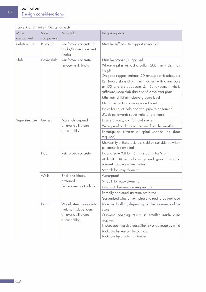
K.29
Sanitation
Table K.3: VIP toilets: Design aspects
Main component
Sub-component
Materials Design aspects
Substructure Pit collar Reinforced concrete or bricks/ stone in cement mortar
Must be sufficient to support cover slab
Slab Cover slab Reinforced concrete, ferrocement, bricks
Must be properly supportedWhere a pit is without a collar, 200 mm wider than the pitOn good support surface, 50 mm support is adequate
Reinforced slabs of 75 mm thickness with 6 mm bars at 150 c/c are adequate. 5:1 Sand/cement mix is sufficient. Keep slab damp for 5 days after pour.
Minimum of 75 mm above ground level
Maximum of 1 m above ground level
Holes for squat-hole and vent pipe to be formed
5% slope towards squat-hole for drainage
Superstructure General Materials depend on availability and affordability
Ensure privacy, comfort and shelter
Waterproof and protect the user from the weather
Rectangular, circular or spiral shaped (no door required)
Movability of the structure should be considered when pit cannot be emptied
Floor Reinforced concrete Floor area = 0.8 to 1.5 m2 (2.35 m2 for VIDP)
At least 100 mm above general ground level to prevent flooding when it rains
Smooth for easy cleaning
Walls Brick and blocks preferredFerrocement not advised
Waterproof
Smooth for easy cleaning
Keep out disease-carrying vectors
Partially darkened structure preferred
Galvanised wire for vent pipe and roof to be provided
Door Wood, steel, composite materials (dependent on availability and affordability)
Face the dwelling, depending on the preference of the users
Outward opening results in smaller inside area requiredInward opening decreases the risk of damage by wind
Lockable by key on the outsideLockable by a catch on inside
K.4 Design considerations

K.30
Sanitation
Table K.3: VIP toilets: Design aspects
Main component
Sub-component
Materials Design aspects
Superstructure Roof Reinforced concrete, corrugated iron, clay/fibre cement tiles, thatch, palm leaves, etc. (dependent on availability and affordability)
Waterproof
Tied to the walls to resist uplift forces
Slope away from the door
Seat Pedestal Brick, mortar, plastic, zinc, fibreglass, ceramic, wood, steel
Beneficiaries to decide
Maximum width of slab opening of 200 mm
Seat opening 250 mm to 300 mm
Seat height 300 to 400 mm
A toilet seat and lid that can close
User needs are taken into account – kiddies seat, ramp for wheelchairs, etc.
Ventilation Ventilation pipe
PVC, uPVC, bricks, blockwork, hessian (steel mesh-supported) etc.
Painted black
Orientated towards the sun
Straight to attract flies upwards and maximise airflow
Preferably on outside of superstructure
Extending more than 500 mm above the highest point of the roof
At least 2 m away from anything that can impede airflow (trees, structures, etc.)
Ventilation openings
Provide without risking privacy
> 3 times the area of ventilation pipe (0.15 m2 is adequate)
Screened
Disease vector control
Fly screen Corrosion resistant material(glass fibre, aluminium, stainless steel, brass, etc.)
1 mm to 1.5 mm mesh openings
Hand washing Basin/sink Brick, mortar, plastic, zinc, fibreglass, ceramic
Running water within 1 m of the toilet
Water Potable/safe water
General considerations
Environmentally sound – protect and conserve water, energy efficient
Vulnerable groups (children, disabled, aged, women) are ensured safe access
Located to provide easy access for maintenance/emptying
K.4Design considerations

K.31
Sanitation
Table K.3: VIP toilets: Design aspects
Main component
Sub-component
Materials Design aspects
General considerations
Downwind of dwelling, not nearer than 10 m and no further than 20 m
Orientated to ensure privacy and comply with cultural preferences (if applicable)
Appropriate solid waste disposal to be planned and designed for (including consideration of menstrual health needs)
Figure K.5: Examples of VIP (L) and VIDP (R) toilets A
ckno
wle
dgem
ent:
DW
AF26
K.4.1.2 Composting toilet
The composting toilet is similar to the VIP toilet and the same design aspects for the superstructure and substructure need to be considered and incorporated. In a composting toilet, excreta fall into a tank/container to which ash or vegetable matter is added. The mixture will decompose to form a good soil conditioner in about four months. Pathogens are killed in the dry alkaline compost, which can be removed for application to the land as a fertiliser. Three types of composting toilets are presented below. In the traditional composting toilet (see Figure K.6), compost is produced continuously. With another type of composting toilet, the contents of the full pit is left to become compost. The pit is then used to plant a tree and a new toilet pit is dug, such as the Arborloo (see Figure K.7). A third composting toilet uses two containers to produce compost in batches, such as the Fossa Alterna (see Figure K.8). More information on composting toilets is available from the World Health Organization.27
K.4 Design considerations

K.32
Sanitation
Figure K.7: The Arborloo
Ada
pted
from
Mor
gan
29
K.4Design considerations
Ring beam
New pit
Used pit
Pit currentlyin use
Tree planted in used pit
Ack
now
ledg
emen
t: Ti
lley
et a
l 28
Vent pipe
Fan
Air ducts
Excess liquid drain
Door for maintenance and organics addition
Withdrawal
Partition wall
Sieve or drainage layer
Figure K.6: Traditional composting toilet

K.33
Sanitation
K.4.1.3 Urine-diverting dry toilet
The urine-diverting dry toilet (UDDT) is a toilet that operates without water and has a divider/receptacle that diverts the urine away from the faeces. The faeces are dried out to be mixed with soil to form a compost. The urine can be collected in a container to be diluted with water and used as a soil conditioner, or it can be diverted to a soakaway. The design aspects for the superstructure of UDDTs are similar to those of the VIP toilet when it is not incorporated as part of the house.
The primary advantage of UDDTs, as compared to conventional dry toilets like VIP toilets, is the conversion of faeces into a dry odourless material. This leads to an odour-free and insect-free toilet that is appreciated by users and allows simple removal and less offensive and safer handling of the faecal material once the storage area has filled up. The functional design elements of a UDDT include source separation of urine and faeces, waterless operation and ventilated vaults or containers for faeces storage and treatment. Comprehensive design details can be obtained from Guidelines for the design, operation and maintenance of urine-diversion sanitation systems31 and from Technology Review of Urine-diverting dry toilets (UDDTs).32
Figure K.8: Fossa Alterna toilet
Ack
now
ledg
emen
t: Ti
lley
et a
l30
K.4 Design considerations

K.34
Sanitation
K.4.1.4 Pour-flush toilet
A pour-flush is a toilet fitted with a trap providing a water seal. It is cleared of faeces by pouring in sufficient quantities of water to wash the solids into the pit and replenish the water seal. The water seal prevents flies, mosquitos and odours reaching the toilet from the pit. The pit may be offset from the toilet by providing a short length of pipe or a covered channel from the pan to the pit. The pan of an offset pour-flush toilet is supported by the ground and the toilet may be within (or attached to) a house. The pour-flush can be retrofitted with a cistern to connect it to a waterborne sanitation system.
The design aspects for the superstructure of a pour-flush toilet are similar to those of the VIP toilet when it is not incorporated as part of the house. More details and information are available from the World Health Organization34
and from Developing a low flush latrine for application in public schools35, available from the WRC.
K.4.1.5 Aqua privy
An aqua privy is a toilet with the superstructure located directly above (or slightly offset of) a watertight holding tank. The tank is kept topped up with either potable water, rainwater, or greywater. The overflow of the tank can be connected to either a solids-free sewer system, or a soakaway. The design aspects for the superstructure are similar to those of the VIP toilet when it is not incorporated as part of the house. More details and information are available from A Guide to the Development of On-Site Sanitation.36
Figure K.9: Examples of a urine-diverting toilet (L) and a pour-flush sanitation system (R)
Ack
now
ledg
emen
t: D
WA
F33
K.4Design considerations

K.35
Sanitation
K.4.1.6 Septic leach field system
Septic tanks form part of the sewage disposal system that can be connected to the outlet of any water-flush latrine. An advantage of a septic tank is that the household has all the benefits of the conventional waterborne sanitation with on-site disposal. The disadvantage is that it requires the periodic removal of sludge.
A typical design of a septic tank is shown in Figure K.11. SANS 10252-2 Water Supply and Drainage for Buildings: Part 2 Drainage installations for buildings provides national standards on septic tank systems. Relevant information is included in Annexure B of SANS 10252-2.38
Figure K.10: An example of an aqua privy
Ack
now
ledg
emen
t: D
WA
F37
Figure K.11: A two-compartment septic tank with access risers and an effluent screen
Ack
now
ledg
emen
t: Ti
lley
et a
l 39
K.4 Design considerations

K.36
Sanitation
K.4.1.7 Anaerobic baffled reactor
An anaerobic baffled reactor is an improved septic tank. The retention time of the liquid in an anaerobic reactor is usually 30 to 50 days, which improves pathogen removal. The system can be connected to a solids-free system that removes the effluent for off-site disposal or to a soakaway, keeping the effluent on site and underground. Figure K.12 illustrates an anaerobic baffled reactor. More information is available from the Compendium of Sanitation Systems and Technologies.40
Figure K.12: An anaerobic baffled reactor (L) and an anaerobic digester (R)
Ack
now
ledg
emen
t: Ti
lley
et a
l 41
K.4.1.8 Anaerobic digester/ Biogas reactor
An anaerobic digester is an airtight container in which the waste is dumped and decomposed. Bacteria within the digester tank breaks down the waste and, as it decomposes, gases such as carbon monoxide, methane, hydrogen, and nitrogen, are released. The gas, known as biogas, is captured in a gas holder to be used later to be combusted, or reacted, with oxygen to create an energy source for such processes as heating and vehicle propulsion.
Refer to SANS 1753 The Construction, installation, commissioning and maintenance of any biogas plan, piping, controls and equipment42 for the relevant standards pertaining to anaerobic digesters and biogas. More information is available from Decentralised Wastewater Treatment Systems (DEWATS) and Sanitation in Developing Countries. A Practical Guide43 and the Compendium of Sanitation Systems and Technologies.44
K.4.1.9 Vacuum sewer system
Vacuum sewer systems make use of a combination of gravity and differential air pressure as the driving force that propels sewage through the sewer network. Vacuum sewer systems consist of three key components: collective chambers, vacuum sewers and the vacuum station. A central vacuum pump station is required to maintain a vacuum (negative pressure) on the collection system (see Figure K.13). The system requires a normally closed vacuum-gravity interface valve at each entry point to seal the lines so that the vacuum can be maintained.45 These valves, located in valve pits, open when a predetermined amount of wastewater accumulates in collecting sumps. The
K.4Design considerations

K.37
Sanitation
resulting differential pressure between the atmosphere and vacuum becomes the driving force that propels the wastewater towards the vacuum station. For design details refer to the Waterborne Sanitation Design Guide46 and the City of Cape Town’s Service Guidelines and Standards for the Water and Sanitation Department.47
Figure K.13: Vacuum sewer system
Ack
now
ledg
emen
t: Bi
lfing
er/
Berg
er 48
K.4.1.10 Small-bore sewer system
Small-bore systems, or small-diameter-gravity (SDG) sewers, or solids-free sewers (SFS) are also called septic-tank-effluent-gravity (STEG) sewers. These systems convey effluent by gravity from an interceptor tank (or septic tank) to a centralised treatment plant or pump station, from where it is conveyed to another collection system. Another variation on this alternative sewer system is the septic-tank-effluent-pumping (STEP) concept. All these systems utilise smaller-diameter pipes placed in shallow trenches that follow the natural contours of the area, thus reducing the capital cost of the pipe, as well as excavation and construction costs. For design detail, refer to the Waterborne Sanitation Design Guide49 published by the WRC.
K.4 Design considerations

K.38
Sanitation
K.4.1.11 Simplified/shallow sewer system
A simplified sewer system is constructed using smaller diameter pipes laid at a shallower depth and at a flatter gradient than conventional sewers in order to remove wastewater from the household environment. Many of the conventional sewer design standards, such as minimum diameter, minimum slopes and minimum depths are relaxed in shallow sewer systems, and community-based construction, operation and maintenance are allowed. Expensive manholes are replaced by simple inspection chambers. Each discharge point is connected to an inspection and/or baffle to prevent solids and trash from entering the system. Another key design feature is that the sewers are laid within the property boundaries rather than beneath central roads. Since the sewers are considered more ‘communal’, they are often referred to as ‘condominial sewers’51. Simplified sewer systems can be installed in almost all types of settlements and are especially appropriate for dense urban settlements. For design detail, refer to the Waterborne Sanitation Design Guide52 published by the WRC.
K.4.1.12 Waterborne sanitation
Waterborne sanitation consists of a flush toilet connected to reticulation that transports sewage away from the user. Section K.4.2, Section K.4.3 and Section K.4.4 apply to the design of waterborne sewerage reticulation. Certain basic guidelines applicable to non-gravity systems (i.e. pump stations and rising mains) are included, but detailed design criteria for these systems are not included, as they are regarded as bulk services. Except in cases where illustrations are provided, the reader is referred to figures in the relevant sections of SANS 1200 Standardised Specification for Civil Engineering Construction.53
Figure K.14: Small-bore sewer system
Ack
now
ledg
emen
t: Ti
lley
et a
l 50
K.4Design considerations

K.39
Sanitation
K.4.2 Sewage flow calculation
Sewers should be designed to avoid possible overflows by making provision for the following flow contributions:
• Regular flow (domestic and/or commercial sewage return flow) plus leakage and base flow (from night flow, leaking cisterns, leaking taps, etc.)
• Infiltration – groundwater seeping through joints/cracks in the pipelines and junctions• Stormwater ingress – during rainstorms, runoff ingress into the system via illegal connections and inundated
junctions
The general procedure for calculating the design flow is illustrated in Figure K.15:
Figure K.15: General procedure for calculating design flow
K.4 Design considerations
Calculate regular flow (incl. leakage
and baseflow)Section K.4.2.1
Calculate groundwater
infiltration Section K.4.2.2
Make allowance for stormwater ingress
Section K.4.2.3
Design flow(IPWWF)
Section K.4.2.4+ + =

K.40
Sanitation
PDDWF (excl. infiltration) (kL/d) = Regular flow (kL/d) + Leakage & base flow (kL/d)
ADDWF (excl. infiltration) (kL/d) = (PDDWF (excl. infiltration) (kL/d)
Peak day factor
Average PDDWF (L/s) = PDDWF ( kL/d)
(24 h × 60 min × 60 sec)
IPDWF (L/s) = Peak Factor × Average PDDWF (L/s)
IPWWF or Design Flow (L/s) = IPDWF (L/s) (1 ‒ Required spare capacity)
Where:
PDDWF = Peak Daily Dry Weather Flow (total wastewater flow representing the peak day in a week)ADDWF = Average Daily Dry Weather Flow (total average wastewater flow)IPDWF = Instantaneous Peak Dry Weather FlowIPWWF = Instantaneous Peak Wet Weather Flow (design flow)
K.4Design considerations
Figure K.16: Sewer outflow hydrograph
0
50
100
150
200
250
300
350
400
450
1 2 3 4 5 6 7 8 9 10 11 12 13 14 15 16 17 18 19 20 21 22 23 24
Flow
(L/s
)
Time (Hours)
Regular flow
Leakage & base flow
Infiltration
Pipe full capacity (L/s)
Average PDDWF (L/s)
IPDWF (L/s)
IPWWF (L/s)
IPWWF = Design Flow ≤ Pipe full flow capacity
IPDWF = Peak Factor x Average PDDWF
Spare Capacity± 30% for Stormwater Ingress

K.41
Sanitation
K.4.2.1 Regular flow
Three methods can be used to calculate the regular flow (including leakage and base flow):
• Unit hydrograph method – if the Average Annual Daily Demand (AADD) is unknown, but land use and Peak Daily Dry Weather Flow (PDDWF) are known
• AADD method – if the AADD, percentage AADD sewer contribution, and land use are known• Sewer flow and peak factor method - if the PDDWF and land use are known (traditional method)
These three methods are discussed in detail and examples are provided.
(i) Unit hydrograph method
This method uses contributor unit hydrographs for different land use categories to calculate the expected theoretical peak flows and sewage volumes. It can be used when the AADD is not known for the specific land use(s). The inflow at a time (t) is calculated using the following formula:
HQt (L/min/unit) = UHt × Peak + Leak
Unit PDDWF (kL/d/unit) = 24 ∑ t =1 HQt × (24 h × 60 min) ÷ 1 000 L
TQt (L/s) = HQt × UQ (kL/d/unit) × 1 000 L ÷ (24 h × 60 min)
× EE × 60 sec 24 ∑ t =1 HQt
Where:
UHt = Unit hydrograph value for land use type at a specific time step (from Table K.5)Peak = Hydrograph peak flow for land use type (from Table K.5) in L/minLeak = Hydrograph leakage and base flow for land use type (from Table K.5) in L/minUQ = Unit PDDWF for land use type (from Table K.4, second last column) in kL/d/unitEE = Number of units or land parcels per land use typeHQt = Calculated unit flow at a specific time step for land use type in L/min/unitTQt = Calculated flow at a specific time step for land use type in L/s
From the unit hydrograph method the following design values can be calculated:
• IPDWF (excl. infiltration) (Instantaneous Peak Dry Weather Flow) calculated as the maximum value of TQt for each land use for the peak day as follows:
IPDWF (excl. infiltration) (L/s) = max (TQ t1..24 )
• PDDWF (excl. infiltration) (Peak Daily Dry Weather Flow) calculated as the average value of TQt for each land use for the peak day, or the sum of the number of units multiplied with the unit PDDWF for each land use:
PDDWF (excl. infiltration) (kL/d) = Number of units [EE] × Unit PDDWF [UQ] (kL/d/unit)
K.4 Design considerations
24
24
1
1

K.42
Sanitation
• ADDWF (excl. infiltration) (Average Daily Dry Weather Flow) can be calculated as the PDDWF (Peak daily dry weather flow for the peak day in the week) divided by the Peak day factor:
ADDWF (excl. infiltration) (kL/d) = PDDWF (excl. infiltration) (kL/d) ÷ Peak day factor
Table K.4 provides the AADD, PDDWF and recommended UH-type for various land use types and densities. The recommended hourly ordinates of each UH-type are tabulated in Table K.5 and illustrated in Figure K.16 for a 24-hour period.
Worked example S1 – Unit hydrograph method
This worked example describes the Unit Hydrograph Method in determining the flow for 50 medium-density residential (UH2) units and 30 business/commercial property (UH7) units. The input data is obtained from Table K.4 and Table K.5 and the calculated values are shown in Table K.6.
Calculate each hourly interval for the ‘medium-density residential’ land use type excluding infiltration:
Example: Calculation for hour 1 of 24-hour time step:
Unit flow* (HQt) for hour 1 = UHt x Peak + Leak = 0.15 x 0.64 L/min/unit + 0.19 L/min/unit = 0.286 L/min/unitCalculated unit PDDWF* = Average of HQt for the 24h period L/min/unit x ( 24 h x 60 min ) ÷ 1 000 L = 0.542 (L/min/unit) x 24 h x 60 min ÷ 1000 L = 0.780 kL/d/unitFlow* (TQt) for hour 1 = HQt L/min/unit x ( UQ kL/d/unit ÷ Calculated Unit PDDWF kL/d/unit ) x EE
units = 0.286 L/min/unit x ( 0.60 kL/d/unit ÷ 0.78 kL/d/unit ) x 50 units ÷ 60 sec = 0.183 L/sNote: * Flow excludes infiltration
Calculate design flow for ‘medium-density residential’ land use type excluding infiltration:
IPDWF* = Maximum of Flow [TQ] over the 24h period = 0.532 L/sPDDWF* = Average of flow [TQ] over the 24h period x (24h x 60min ) ÷ 1 000 L, or = Number of units [EE] x Unit PDDWF [UQ] = 50 units x 0.60 kL/d/unit = 30.0 kL/dADDWF* = PDDWF ÷ Peak day factor = 30.0 kL/d ÷ 1.1 factor = 27.3 kL/dNote: * Flow excludes infiltration
Similarly, the flows for the 30 business/commercial (UH7) units can be calculated with the calculated values shown in Table K.6.
K.4Design considerations

K.43
Sanitation
Table K.4: Demands and hydrographs for different land use categories
Land use Density #1
units/ha
Stand size #2
m²
Unit of
measure
Water demand (AADD)
Sewer flow (excl. infiltration) (Unit PDDWF) #4
kL/ha/d
kL/unit/d #3
% AADD kL/unit/d #3
Unit Hydro-graph(UH)
Residential stands
High density, small sized
20 to 12 400 to 670
kL/unit 11 0.60 to 0.80
80% to 70%
0.48 to 0.56
UH5
Medium density, medium sized
12 to 8 670 to 1 000
kL/unit 9 0.80 to 1.00
70% to 60%
0.56 to 0.60
UH3
Low density, large sized
8 to 5 1 000 to 1 600
kL/unit 8 1.00 to 1.30
60% to 55%
0.60 to 0.72
UH2
Very low density, extra-large sized
5 to 3 1 600 to 2 670
kL/unit 7 1.30 to 2.00
55% to 40%
0.72 to 0.80
UH1
Stands for low-income housing (waterborne sanitation)
High density, small sized
30 to 20 270 to 400
kL/unit 9 0.30 to 0.40
95% to 90%
0.29 to 0.36
UH4
Medium density, medium sized
20 to 12 400 to 670
kL/unit 7 0.40 to 0.50
90% to 85%
0.36 to 0.43
UH4
Low density, extra-large sized
12 to 8 670 to 1000
kL/unit 6 0.50 to 0.60
85% to 80%
0.43 to 0.48
UH4
Stands for low-income housing (dry sanitation)
High density, small sized
30 to 20 270 to 400
kL/unit 7 0.25 to 0.30
n.a. n.a. n.a.
Medium density, medium sized
20 to 12 400 to 670
kL/unit 6 0.30 to 0.35
n.a. n.a. n.a.
Low density, extra-large sized
12 to 8 670 to 1 000
kL/unit 4 0.35 to 0.40
n.a. n.a. n.a.
Group/ cluster housing
High density 60 to 40 130 to 200
kL/unit 21 0.40 to 0.45
95% to 90%
0.38 to 0.41
UH5
Medium density
40 to 30 200 to 270
kL/unit 17 0.45 to 0.50
90% to 85%
0.41 to 0.43
UH5
Low density 30 to 20 270 to 400
kL/unit 14 0.50 to 0.60
85% to 80%
0.43 to 0.48
UH5
K.4 Design considerations

K.44
Sanitation
Table K.4: Demands and hydrographs for different land use categories
Land use Density #1
units/ha
Stand size #2
m²
Unit of
measure
Water demand (AADD)
Sewer flow (excl. infiltration) (Unit PDDWF) #4
kL/ha/d
kL/unit/d #3
% AADD kL/unit/d #3
Unit Hydro-graph(UH)
Flats
Very high density
100 to 80
80 to 100
kL/unit 25 0.25 to 0.30
100% to 98%
0.25 to 0.29
UH6
High density 80 to 60 100 to 130
kL/unit 23 0.30 to 0.35
98% to 97%
0.29 to 0.34
UH6
Medium density
60 to 50 130 to 160
kL/unit 21 0.35 to 0.40
97% to 96%
0.34 to 0.38
UH6
Low density 50 to 40 160 to 200
kL/unit 19 0.40 to 0.45
96% to 95%
0.38 to 0.43
UH6
Agricultural holdings
Including irrigation
< 3 < 2670 kL/unit 12 4.00 40% 1.60 UH1
Domestic water only
< 3 < 2670 kL/unit 6 2.00 80% 1.60 UH1
Golf estate - excl. golf course water requirements
< 3 < 2670 kL/unit 9 3.00 40% 1.20 UH2
Retirement village20 to 12 400 to
670kL/unit 11 0.60 to
0.8080% to
70%0.48 to
0.56UH5
Business/commercialFAR = 0.4
n.a. kL/100m² #2
21 0.65 80% 0.52 UH7
IndustrialFAR = 0.4
n.a. kL/100m² #2
13 0.40 80% 0.32 UH10
Government institutionsFAR = 0.4
n.a. kL/100m² #2
13 0.40 80% 0.32 UH9
WarehousingFAR = 0.4
n.a. kL/100m² #2
10 0.30 80% 0.24 UH11
InstitutionalFAR = 0.4
n.a. kL/100m² #2
20 0.60 80% 0.48 UH9
Municipal servicesFAR = 0.4
n.a. kL/100m² #2
20 0.60 80% 0.48 UH9
EducationalFAR = 0.4
n.a. kL/100m² #2
20 0.60 65% 0.39 UH8
Cemeteries n.a. n.a. kL/ha 12 n.a. n.a. n.a. n.a.
Parks n.a. n.a. kL/ha 12 n.a. n.a. n.a. n.a.
Sports fields n.a. n.a. kL/ha 12 n.a. n.a. n.a. n.a.Notes: #1 - Assumed net area factor = 0.8 x gross area (20% allowance for roads, servitudes and open spaces)#2 - Floor area#3 - Unit type as defined in column ‘Unit of measure’ #4 - Regular flow + leakage and base flowFAR (Floor Area Ratio) is the ratio of the floor area of a building to its site area. Also referred to as FSR (Floor Space Ratio).
K.4Design considerations

K.45
Sanitation
Table K.5: Sewer unit hydrographs
Definition of unit hydrographs Unit Hydrograph (UH) Number UH1 UH2 UH3 UH4 UH5 UH6 UH7 UH8 UH9 UH10 UH11 UH12 UH13 UH14 UH15 Land use(s) following typical UH pattern
Resid
entia
l Ve
ry lo
w d
ensit
y
Resid
entia
l lo
w d
ensit
y
Resid
entia
l m
ediu
m d
ensit
y
Low
-inco
me
hous
ing
Gro
up/
clus
ter
hous
ing
Flat
s
Busin
ess/
co
mm
erci
al
Educ
atio
nal
Mun
icip
al se
rvic
es/
in
stitu
tiona
l
Indu
stria
l
Mul
tipur
pose
/
mix
ed/
othe
r
Agr
icul
tura
l ho
ldin
gs
Non
e (e
.g. P
ublic
ope
n sp
ace)
Unk
now
n
Larg
e us
ers
(per
kL
AA
DD
)
Hr Dimensionless flow ordinates (relative to hydrograph peak) 1 0.15 0.17 0.15 0.09 0.15 0.15 0.08 0.08 0.08 0.09 0.08 0.17 0.00 0.09 0.09 2 0.08 0.10 0.09 0.05 0.09 0.09 0.07 0.07 0.07 0.07 0.07 0.10 0.00 0.07 0.07 3 0.06 0.05 0.07 0.06 0.07 0.07 0.06 0.06 0.06 0.06 0.06 0.05 0.00 0.06 0.06 4 0.05 0.05 0.05 0.19 0.05 0.05 0.05 0.05 0.05 0.05 0.05 0.05 0.00 0.05 0.05 5 0.05 0.05 0.15 0.49 0.15 0.15 0.06 0.06 0.06 0.06 0.06 0.05 0.00 0.08 0.08 6 0.11 0.44 0.77 0.80 0.77 0.77 0.08 0.08 0.08 0.10 0.08 0.44 0.00 0.25 0.25 7 0.67 1.00 1.00 0.83 1.00 1.00 0.15 0.15 0.15 0.47 0.15 1.00 0.00 0.69 0.69 8 1.00 0.91 0.98 0.93 0.98 0.98 0.34 0.34 0.34 0.68 0.34 0.91 0.00 0.95 0.95 9 0.87 0.94 0.73 1.00 0.73 0.73 0.83 0.83 0.83 0.84 0.83 0.94 0.00 1.00 1.00 10 0.85 0.84 0.66 0.96 0.66 0.66 0.94 0.94 0.94 0.93 0.94 0.84 0.00 0.89 0.89 11 0.82 0.74 0.72 0.89 0.72 0.72 1.00 1.00 1.00 0.94 1.00 0.74 0.00 0.87 0.87 12 0.71 0.59 0.65 0.75 0.65 0.65 0.98 0.98 0.98 0.89 0.98 0.59 0.00 0.83 0.83 13 0.56 0.48 0.61 0.71 0.61 0.61 0.94 0.94 0.94 0.75 0.94 0.48 0.00 0.60 0.60 14 0.50 0.41 0.57 0.74 0.57 0.57 0.89 0.89 0.89 0.81 0.89 0.41 0.00 0.59 0.59 15 0.46 0.40 0.63 0.76 0.63 0.63 0.88 0.88 0.88 0.95 0.88 0.40 0.00 0.53 0.53 16 0.44 0.38 0.66 0.73 0.66 0.66 0.92 0.92 0.92 1.00 0.92 0.38 0.00 0.53 0.53 17 0.41 0.39 0.70 0.70 0.70 0.70 0.84 0.84 0.84 0.89 0.84 0.39 0.00 0.47 0.47 18 0.38 0.48 0.68 0.66 0.68 0.68 0.35 0.35 0.35 0.66 0.35 0.48 0.00 0.37 0.37 19 0.45 0.53 0.72 0.59 0.72 0.72 0.22 0.22 0.22 0.35 0.22 0.53 0.00 0.28 0.28 20 0.49 0.52 0.70 0.51 0.70 0.70 0.15 0.15 0.15 0.22 0.15 0.52 0.00 0.24 0.24 21 0.45 0.51 0.68 0.38 0.68 0.68 0.12 0.12 0.12 0.17 0.12 0.51 0.00 0.20 0.20 22 0.50 0.49 0.57 0.26 0.57 0.57 0.11 0.11 0.11 0.14 0.11 0.49 0.00 0.16 0.16 23 0.40 0.42 0.44 0.18 0.44 0.44 0.10 0.10 0.10 0.12 0.10 0.42 0.00 0.15 0.15 24 0.29 0.28 0.22 0.13 0.22 0.22 0.09 0.09 0.09 0.10 0.09 0.28 0.00 0.13 0.13 Unit hydrograph parameters (L/min)Hydrograph Peak
1.69 1.04 0.64 0.21 0.37 0.24 2.46 4.97 1.93 2.19 1.75 0.59 0.00 0.55 0.50
% of AADD 40% 55% 60% 70% 80% 90% 80% 65% 80% 80% 60% 80% 0% 55% 60%Leakage & base flow
0.26 0.21 0.19 0.15 0.14 0.21 1.05 2.12 0.83 1.04 0.75 0.15 0.00 0.23 0.21
Flow hydrograph volumes (L/d)Regular flow 1090 697 507 169 293 190 1513 3057 1187 1490 1076 395 0 333 302Leakage & base flow
374 302 274 216 202 302 1512 3053 1195 1498 1080 216 0 331 302
TOTAL FLOW 1464 999 780 385 495 492 3025 6109 2382 2988 2156 611 0 664 605
K.4 Design considerations

K.46
Sanitation
Figure K.17: Hourly flow ordinates relative to Hydrograph Peak (residential land use)
0.0
0.5
1.0
1.5
2.0
2.5
1 2 3 4 5 6 7 8 9 10 11 12 13 14 15 16 17 18 19 20 21 22 23 24
Flow
(l/
min
)
Hours
Residential land use
ResidentialLow density
ResidentialNormal density
ResidentialMedium density
Low IncomeHousing
Group/ClusterHousing
Flats
K.4Design considerations

K.47
Sanitation
Table K.6: Worked example S1 – Unit hydrograph method
Input Data and data from Table K.4 and Table K.5
Land use #1 Medium-density residential Business and commercial Total
Number of units [EE] #1 50 30
Unit hydrograph type #2 UH3 UH7
Peak flow (L/min) #3 0.64 2.46
Leakage and base flow (L/min) #3 0.19 1.05
Unit PDDWF [UQ] (kL/d/unit) #2 0.60 0.52
Peak day factor #1 1.1
Figure K.18: Hourly flow ordinates relative to Hydrograph Peak (other land uses)
0.0
1.0
2.0
3.0
4.0
5.0
6.0
7.0
8.0
1 2 3 4 5 6 7 8 9 10 11 12 13 14 15 16 17 18 19 20 21 22 23 24
Flow
(l/
min
)
Hours
Other land uses
Business/Commercial
Educational Municipal Services/Institutional
Industrial Multipurpose/Mixed/Other
Unknown
K.4 Design considerations

K.48
Sanitation
Table K.6: Worked example S1 – Unit hydrograph method
Calculations (Regular flow + leakage and base flow)
Hour [t]
Unit hyd. values #3
[UH]
Unit flow [HQ]
(L/min/unit)
Flow [TQ] (L/s)
Unit hyd. values #3
[UH]
Unit flow [UQ]
(L/min/unit)
Flow [TQ] (L/s)
Total flow (L/s)
1 0.15 0.286 0.183 0.08 1.247 0.107 0.290
2 0.09 0.248 0.159 0.07 1.222 0.105 0.264
3 0.07 0.235 0.150 0.06 1.198 0.103 0.253
4 0.05 0.222 0.142 0.05 1.173 0.101 0.243
5 0.15 0.286 0.183 0.06 1.198 0.103 0.286
6 0.77 0.683 0.437 0.08 1.247 0.107 0.545
7 1.00 0.830 0.532 0.15 1.419 0.122 0.654
8 0.98 0.817 0.524 0.34 1.886 0.162 0.686
9 0.73 0.657 0.421 0.83 3.092 0.266 0.687
10 0.66 0.612 0.392 0.94 3.362 0.289 0.681
11 0.72 0.651 0.417 1.00 3.510 0.302 0.719
12 0.65 0.606 0.388 0.98 3.461 0.297 0.686
13 0.61 0.580 0.372 0.94 3.362 0.289 0.661
14 0.57 0.555 0.355 0.89 3.239 0.278 0.634
15 0.63 0.593 0.380 0.88 3.215 0.276 0.656
16 0.66 0.612 0.392 0.92 3.313 0.285 0.677
17 0.70 0.638 0.409 0.84 3.116 0.268 0.677
18 0.68 0.625 0.401 0.35 1.911 0.164 0.565
19 0.72 0.651 0.417 0.22 1.591 0.137 0.554
20 0.70 0.638 0.409 0.15 1.419 0.122 0.531
21 0.68 0.625 0.401 0.12 1.345 0.116 0.516
22 0.57 0.555 0.355 0.11 1.321 0.114 0.469
23 0.44 0.472 0.302 0.10 1.296 0.111 0.414
24 0.22 0.331 0.212 0.09 1.271 0.109 0.321
Hydrograph PDDWF (kL/d/unit) 0.780 3.025
IPDWF (excl. infiltration) (L/s) 0.532 0.302 0.719
PDDWF (excl. infiltration) (kL/d) 30.0 15.6 45.6
ADDWF (excl. infiltration) (kL/d) 27.3 41.5Notes:#1 - Example input data#2 - Obtain from Table K.4 : Demands and hydrographs for different land use categories#3 - Obtain from Table K.5 : Sewer unit hydrographs
K.4Design considerations

K.49
Sanitation
(ii) AADD Method
The AADD method, as opposed to the unit hydrograph method, uses the actual or theoretical average annual daily demand (AADD), calculated per land use, to determine the sewage flow in the pipe at any time (‘t’). This methodcan only be used if the AADD is known. This is a more accurate method as it gives a more realistic view of the flow pattern. The flow is calculated using the following formulae:
HQt (L/min/unit) = UH
t × Peak + Leak
Unit PDDWF (kL/d/unit) = 24 ∑ t =1 HQt × (24 h × 60 min) ÷ 1000 L
TQt (L/s) = HQt × AADD (kL/d/unit) × Ratio ÷ 100 × 1000 L ÷ (24 h × 60 min)
× EE ÷ 60 sec 24 ∑ t =1 HQt (L/min/unit)
Where:
UHt = Unit hydrograph value for land use type at a specific time step (from Table K.5)Peak = Hydrograph peak flow for land use type (from Table K.5) in L/minLeak = Hydrograph leakage and base flow for land use type (from Table K.5) in L/minUQ = Unit PDDWF for land use type (from Table K.4, second last column) in kL/d/unitAADD = Unit AADD for land use type (from Table K.4) in kL/d/unitRatio = The Ratio % of AADD (from Table K.4)EE = Number of units or land parcels per land use typeHQt = Calculated unit flow at a specific time step for land use type in L/min/unitTQt = Calculated flow at a specific time step for land use type in L/s
Figure K.19: Worked example S1: Outflow hydrograph
K.4 Design considerations
241
1 24
Note: A peak factor is already included in the hydrograph used to calculate the flows. Therefore a seperate peak factor does not need to be applied.
1
0,0
0,1
0,2
0,3
0,4
0,5
0,6
0,7
0,8
9 175 113 212 10 186 14 223 11 197 15 234 12 208 16 24Hours
Medium density residential Business and commercial Total
Flow
(L/
s)

K.50
Sanitation
Worked example S2 – AADD method
This worked example describes the AADD method to determine the flow for 50 medium-density residential (UH2) units and 30 business/commercial property (UH7) units. The first two equations are the same as used for the Unit Hydrograph method to calculate unit flow and unit PDDWF, but the equation for TQt is slightly modified to incorporate the AADD adjustment. The input data is as obtained from Table K.4 and Table K.5 and the calculated values are shown in Table K.7.
Calculate for each hourly interval for the ‘medium-density residential’ land use type excluding infiltration:
Example: Calculation for hour 1 of 24-hour time step:
Unit Flow* (HQt) for hour 1 = UHt x Peak + Leak = 0.15 x 0.64 L/min/unit + 0.19 L/min/unit = 0.286 L/min/unitCalculated Unit PDDWF* = Average of HQt for the 24h period L/min/unit x (24 h x 60 min) ÷ 1 000 L = 0.542 (L/min/unit) x 24 h x 60 min ÷ 1 000 L = 0.780 kL/d/unitCalculated PDDWF* (UQ) = AADD kL/d/unit x Ratio % ÷ 100 = 1.00 kL/d/unit x 60% ÷ 100 = 0.60 kL/d/unitFlow* (TQt) for hour 1 = HQt L/min/unit x (UQ kL/d/unit ÷ Calculated Unit PDDWF kL/d/unit) x EE
units = 0.286 L/min/unit x (0.60 kL/d/unit ÷ 0.78 kL/d/unit) x 50 units ÷ 60 sec = 0.183 L/sNote: * Flow excludes infiltration
Calculate design flow for ‘medium-density residential’ land use type excluding infiltration:
IPDWF* = Maximum of Flow [TQ] over the 24h period = 0.532 L/sPDDWF* = Average of Flow [TQ] over the 24h period x (24h x 60min ) ÷ 1 000 L, or = Number of units [EE] x Unit PDDWF [UQ] = 50 units x 0.60 kL/d/unit = 30.0 kL/dADDWF* = PDDWF ÷ Peak day factor = 30.0 kL/d ÷ 1.1 factor = 27.3 kL/dNote: * Flow excludes infiltration
Similarly, the flows for the 30 business/commercial (UH7) units can be calculated with the values shown in Table K.6.
K.4Design considerations

K.51
Sanitation
Table K.7: Worked example S2 – AADD method
Input and data from Table K.4 and Table K.5
Land use #¹ Medium-density residential Business and commercial Total
Number of units (EE) #1 50 30
Unit hydrograph type #2 UH3 UH7
Hydrograph peak (L/min) #3 0.64 2.46
Leakage and base flow (L/min) #3 0.19 1.05
AADD (kL/d/unit) #2 1.00 0.65
Ratio % of AADD #2 60% 80%
Unit PDDWF [UQ] (kL/d/unit) 0.60 0.52
Peak day factor #1 1.1
Calculations (Regular flow + leakage and base flow)
Hour [t]
Unit hyd. values #3
[UH]
Unit flow [HQ]
(L/min/unit)
Flow [TQ] (L/s)
Unit hyd. values #3
[UH]
Unit flow [UQ]
(L/min/unit)
Flow [TQ] (L/s)
Total flow (L/s)
1 0.15 0.286 0.183 0.08 1.247 0.107 0.290
2 0.09 0.248 0.159 0.07 1.222 0.105 0.264
3 0.07 0.235 0.150 0.06 1.198 0.103 0.253
4 0.05 0.222 0.142 0.05 1.173 0.101 0.243
5 0.15 0.286 0.183 0.06 1.198 0.103 0.286
6 0.77 0.683 0.437 0.08 1.247 0.107 0.545
7 1.00 0.830 0.532 0.15 1.419 0.122 0.654
8 0.98 0.817 0.524 0.34 1.886 0.162 0.686
9 0.73 0.657 0.421 0.83 3.092 0.266 0.687
10 0.66 0.612 0.392 0.94 3.362 0.289 0.681
11 0.72 0.651 0.417 1.00 3.510 0.302 0.719
12 0.65 0.606 0.388 0.98 3.461 0.297 0.686
13 0.61 0.580 0.372 0.94 3.362 0.289 0.661
14 0.57 0.555 0.355 0.89 3.239 0.278 0.634
15 0.63 0.593 0.380 0.88 3.215 0.276 0.656
16 0.66 0.612 0.392 0.92 3.313 0.285 0.677
17 0.70 0.638 0.409 0.84 3.116 0.268 0.677
18 0.68 0.625 0.401 0.35 1.911 0.164 0.565
19 0.72 0.651 0.417 0.22 1.591 0.137 0.554
20 0.70 0.638 0.409 0.15 1.419 0.122 0.531
21 0.68 0.625 0.401 0.12 1.345 0.116 0.516
22 0.57 0.555 0.355 0.11 1.321 0.114 0.469
23 0.44 0.472 0.302 0.10 1.296 0.111 0.414
24 0.22 0.331 0.212 0.09 1.271 0.109 0.321
Hydrograph PDDWF (kL/d/unit)
0.780 3.025
K.4 Design considerations
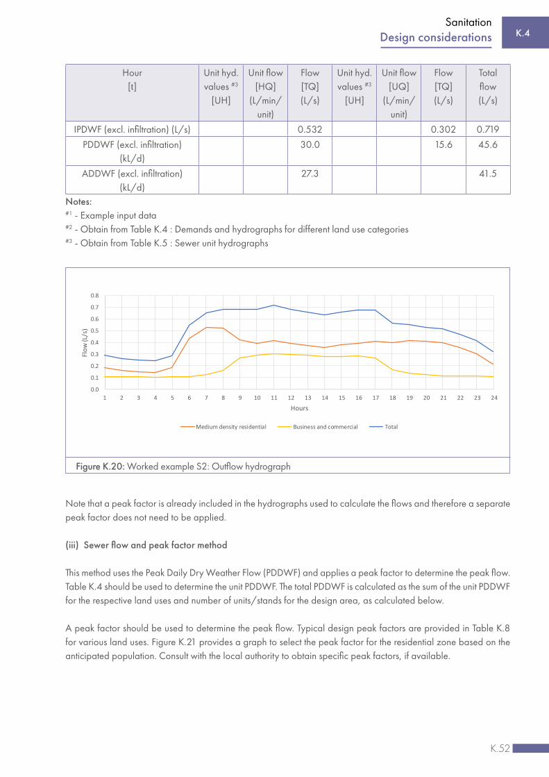
K.52
Sanitation
Hour [t]
Unit hyd. values #3
[UH]
Unit flow [HQ]
(L/min/unit)
Flow [TQ] (L/s)
Unit hyd. values #3
[UH]
Unit flow [UQ]
(L/min/unit)
Flow [TQ] (L/s)
Total flow (L/s)
IPDWF (excl. infiltration) (L/s) 0.532 0.302 0.719
PDDWF (excl. infiltration) (kL/d)
30.0 15.6 45.6
ADDWF (excl. infiltration) (kL/d)
27.3 41.5
Notes:#1 - Example input data#2 - Obtain from Table K.4 : Demands and hydrographs for different land use categories#3 - Obtain from Table K.5 : Sewer unit hydrographs
Figure K.20: Worked example S2: Outflow hydrograph
0.0
0.1
0.2
0.3
0.4
0.5
0.6
0.7
0.8
1 2 3 4 5 6 7 8 9 10 11 12 13 14 15 16 17 18 19 20 21 22 23 24
Flow
(L/s
)
Hours
Medium density residential Business and commercial Total
Note that a peak factor is already included in the hydrographs used to calculate the flows and therefore a separate peak factor does not need to be applied.
(iii) Sewer flow and peak factor method
This method uses the Peak Daily Dry Weather Flow (PDDWF) and applies a peak factor to determine the peak flow.Table K.4 should be used to determine the unit PDDWF. The total PDDWF is calculated as the sum of the unit PDDWF for the respective land uses and number of units/stands for the design area, as calculated below.
A peak factor should be used to determine the peak flow. Typical design peak factors are provided in Table K.8 for various land uses. Figure K.21 provides a graph to select the peak factor for the residential zone based on the anticipated population. Consult with the local authority to obtain specific peak factors, if available.
K.4Design considerations

K.53
Sanitation
Table K.8: Peak factors
Land use Peak factor
Residential – see Figure K.16 1.8 to 2.5
Business/commercial 1.3 to 1.5
Industrial – light 2.5 to 4.0
Industrial – heavy 2.0 to 3.0
Clinics, restaurants, laundromats and hotels 1.8 to 2.5Note: This method does not use the hydrograph peak, and thus a peak factor needs to be applied.
The peak flow rate, IPDWF (excluding infiltration), should be calculated as follows for each land use category:
IPDWF (excl. infiltration) (L/s) = Number of units [EE] × PDDWF (kL/d/unit) × PF × 1 000 ÷ (24 h × 60 min × 60 sec)
PDDWF (excl. infiltration) (kL/d) = Number of units [EE] × Unit PDDWF [UQ] (kL/d/unit)
ADDWF (excl. infiltration) (kL/d) = PDDWF (kL/d) ÷ Peak day factor
Where:
PF = Peak factor (from Table K.8)UQ = Unit PDDWF for land use type (from Table K.4, second last column) in kL/d/unitEE = Number of units or land parcels per land use type
Use Figure K.21 for selecting a peak factor for residential areas where the anticipated population is known. The peak factor reduces due to attenuation of peak flows in gravity sewer systems as the contributor area and population increase. The maximum recommended peak factor for residential areas is 2.5. If actual local peak factors are available, these should be used instead.
K.4 Design considerations

K.54
Sanitation
Worked example S3 – Sewer flow and peak factor method
The same land-use categories and units are used for this worked example as for the examples above.
Table K.9: Worked example S3 – Sewer flow and peak factor method
Input and data from Table K.4, Table K.8 and Figure K.16
Land use #1 Medium-density residential Business and commercial Total
Number of units [EE] #1 50 30
Unit PDDWF [UQ] (kL/d/unit) #2 0.60 0.52
Persons per unit #3 5 n/a
Peak factor #3 2.5 1.50
Peak day factor #1 1.1
Calculations
Total number of persons 250 n/a
IPDWF (excl. infiltration) (L/s) 0.868 0.271 1.139
PDDWF (excl. infiltration) (kL/d) 30.0 15.6 45.6
ADDWF (excl. infiltration) (kL/d) 27.3 14.2 41.5Notes :#1 - Example input data#2 - Obtain from Table K.4: PDDWF (excluding infiltration) for different land use categories #3 - Obtain from Table K.8: Peak factors and Figure K.16: Peak factors for residential land use
Figure K.21: Peak factors for residential land use
1.00
1.50
2.00
2.50
3.00
3.50
1 2 3 4 5 6 7 8
Peak
fact
or
Population served - 000's (at 5 persons per erf)
Peak Factor Maximum recommended
K.4Design considerations
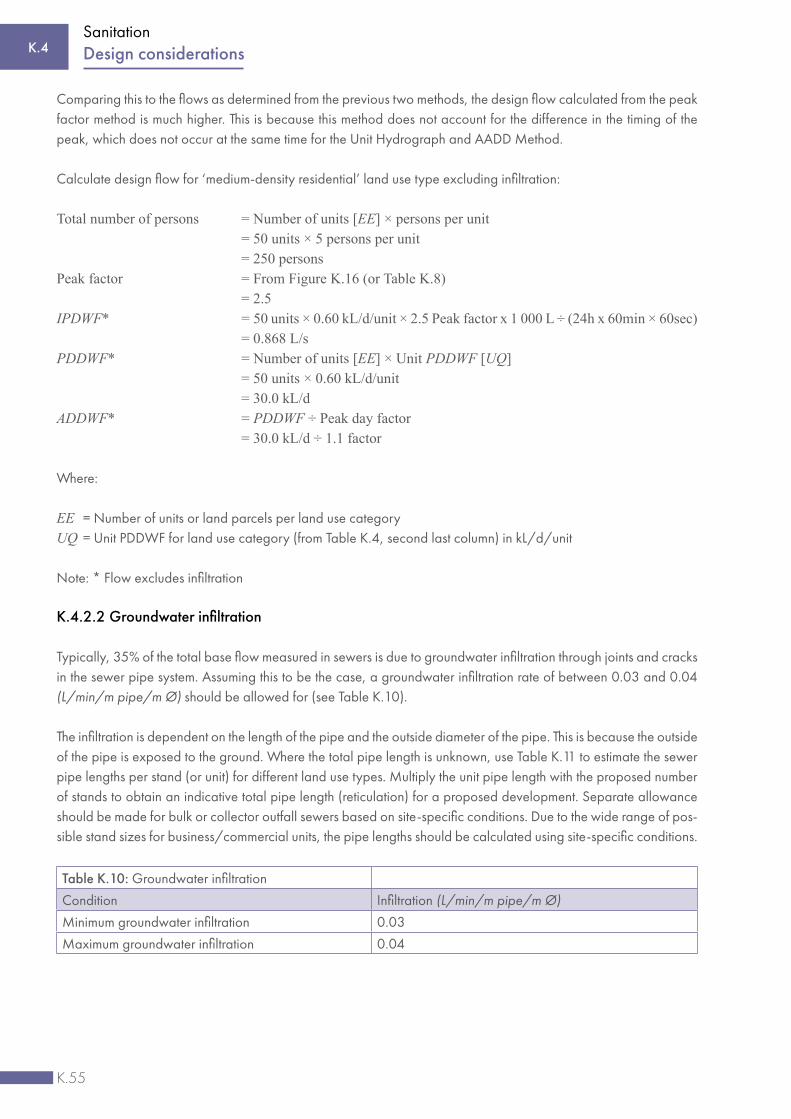
K.55
Sanitation
Comparing this to the flows as determined from the previous two methods, the design flow calculated from the peak factor method is much higher. This is because this method does not account for the difference in the timing of the peak, which does not occur at the same time for the Unit Hydrograph and AADD Method.
Calculate design flow for ‘medium-density residential’ land use type excluding infiltration:
Total number of persons = Number of units [EE] × persons per unit = 50 units × 5 persons per unit = 250 personsPeak factor = From Figure K.16 (or Table K.8) = 2.5 IPDWF* = 50 units × 0.60 kL/d/unit × 2.5 Peak factor x 1 000 L ÷ (24h x 60min × 60sec) = 0.868 L/sPDDWF* = Number of units [EE] × Unit PDDWF [UQ] = 50 units × 0.60 kL/d/unit = 30.0 kL/dADDWF* = PDDWF ÷ Peak day factor = 30.0 kL/d ÷ 1.1 factor
Where:
EE = Number of units or land parcels per land use categoryUQ = Unit PDDWF for land use category (from Table K.4, second last column) in kL/d/unit
Note: * Flow excludes infiltration
K.4.2.2 Groundwater infiltration
Typically, 35% of the total base flow measured in sewers is due to groundwater infiltration through joints and cracks in the sewer pipe system. Assuming this to be the case, a groundwater infiltration rate of between 0.03 and 0.04 (L/min/m pipe/m Ø) should be allowed for (see Table K.10).
The infiltration is dependent on the length of the pipe and the outside diameter of the pipe. This is because the outside of the pipe is exposed to the ground. Where the total pipe length is unknown, use Table K.11 to estimate the sewer pipe lengths per stand (or unit) for different land use types. Multiply the unit pipe length with the proposed number of stands to obtain an indicative total pipe length (reticulation) for a proposed development. Separate allowance should be made for bulk or collector outfall sewers based on site-specific conditions. Due to the wide range of pos-sible stand sizes for business/commercial units, the pipe lengths should be calculated using site-specific conditions.
Table K.10: Groundwater infiltration
Condition Infiltration (L/min/m pipe/m Ø)
Minimum groundwater infiltration 0.03
Maximum groundwater infiltration 0.04
K.4 Design considerations

K.56
Sanitation
Table K.11: Typical pipe length (reticulation) per stand/plot
Land useStand Size #1
Pipe Length #2
m² m
Residential stands
High density, small sized 400 to 670 10 to 13
Medium density, medium sized 670 to 1 000 13 to 16
Low density, large sized 1 000 to 1 600 16 to 20
Very low density, extra-large sized 1 600 to 2 670 20 to 26
Stands for low income housing (waterborne sanitation)
High density, small sized 270 to 400 8 to 10
Medium density, medium sized 400 to 670 10 to 13
Low density, extra-large sized 670 to 1 000 13 to 16
Group/cluster housing
High density 130 to 200 6 to 7
Medium density 200 to 270 7 to 8
Low density 270 to 400 8 to 10
Flats
Very high density 80 to 100 4 to 5
High density 100 to 130 5 to 6
Medium density 130 to 160 6 to 6
Low density 160 to 200 6 to 7
Agricultural holdingsIncluding irrigation < 2 670 > 26
Domestic water only < 2 670 > 26
Golf estate - excluding golf course water requirements < 2 670 > 26
Retirement village 400 to 670 10 to 13Notes :#1 - Assumed net area factor = 0.8 x gross area (20% allowance for roads, servitudes and open spaces)#2 - Calculation based on a square shape stand/plot
Worked example S4 – Groundwater infiltration
For the proposed development comprising 50 medium-density residential units and 30 business/commercial units (as was used in previous examples), the total sewer pipe length should be estimated from Table K.11 as follows:
For the medium-density residential category, estimate the pipe length from Table K.11 = 15m x 50 units = 750 m
For the business/commercial units category, estimate the pipe length (assumed length) = 250 mTotal pipe length = 1 000 m
Assume that all reticulation is 150 mm Ø with no further allowance needed for bulk or collector outfalls. The ground-water infiltration can thus be calculated using the following formula with the results as indicated in Table K.12:
Infiltration flow (L/s) = Infiltration rate (L/min/m/m) × Pipe length (m) × Pipe diameter (m) ÷ 60 sec
K.4Design considerations

K.57
Sanitation
Table K.12: Worked example S4 – Groundwater infiltration
Input data
Pipe length (m) #1 1000
Pipe inside diameter (mm) #1 150
Infiltration rate (L/min/m pipe/m Ø) #2 0.04
Calculations - Infiltration
Peak flow (L/s) Daily flow (kL/d)
Groundwater infiltration flow 0.100 8.6Notes:#1 - Example input data (See Table K.11)#2 - See Table K.10 for recommended groundwater infiltration
The groundwater infiltration flow should be calculated as follows:
Groundwater infiltration flow = 0.04 L/min/m/m x 1 000 m x (150 mm ÷ 1 000) ÷ 60 sec = 0.100 L/s = 0.10 L/s x (24 h x 60 min x 60 sec ÷ 1 000 = 8.6 kL/d
K.4.2.3 Allowance for stormwater ingress
Gravity sewers should be sized not only to accommodate the peak flow during dry weather conditions (IPDWF incl. infiltration), but a spare capacity allowance should be provided for to accommodate stormwater ingress as was illustrated in Figure K.16. The percentage spare capacity allowance criteria for stormwater ingress are to be obtained from the local authority. In the absence of such local criteria, use 30% as recommended for reticulation, and between 15% and 30% as recommended for outfall sewers. Refer to the following section for the calculation.
K.4.2.4 Design flow calculation
The calculation of the design flow or IPWWF (instantaneous peak wet weather flow), as detailed in preceding sec-tions, can be summarised as follows:
Step 1: Calculate the IPDWF (instantaneous peak dry weather flow) excluding groundwater infiltration (Section K.4.2.1)
Step 2: Calculate the groundwater infiltration (Section K.4.2.2)
Step 3: Calculate the IPDWF (instantaneous peak dry weather flow) including groundwater infiltration as follows:
IPDWF (L/s) = IPDWF (excl. Infiltration) (L/s) + Infiltration flow (L/s)
Step 4: Calculate the design flow or IPWWF (instantaneous peak wet weather flow) as follows:
Design Flow or IPWWF (L/s) = IPDWF incl infiltration (L/s)
(1 – spare capacity for stormwater ingress)
K.4 Design considerations

K.58
Sanitation
K.4.3 Hydraulic design guidelines for waterborne sanitation systems
K.4.3.1 Hydraulic spare capacity calculation
The different spare capacity types are illustrated in Figure K.22.
K.4Design considerations
Figure K.22: Absolute and relative spare capacity
0
5
10
15
20
25
30
35
1 2 3 4 5 6 7 8 9 10 11 12 13 14 15 16 17 18 19 20 21 22 23 24
Flow
(L/s
)
Time (Hours)
Flow hydrograph Upstream Pump flow Pipe full capacity (L/s)
Relative Capacity
Hydraulic Spare Capacity
Absolute Capacity
Full Flow Capacity (L/s)
IPDWF (L/s)
Upstream Pump Flow (L/s)
RelativeAbsolute
Spare Capacity

K.59
Sanitation
The ‘spare capacity’ for a regular pipe in a gravity system, which is unaffected by upstream pumps, is defined as follows:
Absolute spare capacity (%) = Full flow pipe capacity (L/s) - Max flow (IPDWF) (L/s)
Full flow pipe capacity (L/s)
The relative spare capacity is the spare hydraulic capacity expressed as a percentage of the relative capacity, which is the capacity of the pipe less the total upstream continuous pump flow rate.
If there are pumps upstream that pump at a continuous rate, it is necessary to consider the relative effect of these pumps on the spare capacity in the downstream pipes. Part of the capacity should cater for the continuous pump flow. Any spare capacity should be expressed as a percentage of the remaining available capacity, i.e. the relative capacity of the pipe, which is the total capacity less the effect of the upstream pumps.
Relative spare capacity (%) = Full flow pipe capacity (L/s) - Max flow (IPDWF) (L/s)
x 100 Full flow pipe capacity (L/s) - Upstream continuous pump rate (L/s)
It should be noted that in the case of variable speed pumps, the amount of flow that flows into the pump structure is pumped out, unless the flow is more than the capacity of the pump; then it overflows. For continuous speed pumps, the pump flow rate is constant, regardless of the inflow.
Worked example S5: Hydraulic capacity
The example below shows that spare capacity is below 30%, assuming this is the minimum hydraulic spare capacity allowance for stormwater ingress. Thus the pipe is too small and should be upgraded.
If the upstream continuous pump flow rate is excluded, the relative spare capacity is more than 30%. Thus no upgrade is required.
Table K.13: Worked example S5 – Hydraulic capacity
Input data
Pipe’s full-flow capacity (L/s) #1 32.0
Max flow (IPDWF) (L/s) #1 28.0
Total upstream continuous flow rate (L/s) #1 20.0
Spare capacity required #1 30%
Calculations
Absolute spare capacity
Spare capacity (L/s) 4.0
Available 12.5%
Relative spare capacity
Spare capacity (L/s) 4.0
Max flow (IPDWF) excluding continuous pump flow rate (L/s) 8.0
Available 33.3%Note: #1 - Example input data
K.4 Design considerations

K.60
Sanitation
K.4.3.2 Velocity calculation
(i) Gravity sewers
The following flow formulae are used for the calculation of velocity and flow in sewers pipe sections during normal depth conditions (slope of the water surface and channel bottom is the same and the water depth remains constant).
Table K.14: Flow formulae
Formula name Formula Roughness constant
Mannings Q = VA = n AR S (n = 0.012)
Chezy Q = VA = 18log kS A RS(KS = 0.600)
Colebrook-White f = – 2log10 (3.7DH + Re f )
KutterC =
23 + S0 + n
1+ R 23 + S0
V = C RS
(n = 0.012)
Where:
A = Cross-sectional area of flow/conduit (m2) R = Hydraulic radius (m) S = Gradient (assuming uniform flow) n = Manning’s roughness coefficient – dependent on material typekS or = Absolute roughness of conduit (m) C = Chezy roughness coefficient f = Darcy-Weisbach friction factorDH = Hydraulic diameter (m)Re = Reynolds number
These formulae are used assuming full flow in the pipe. Any of the above formulae can be used as long as they produce values approximately the same as the equivalent Colebrook-White formula that uses a KS of 0.6. For modelling purposes, the general Manning roughness coefficient is 0.012, but it is dependent on the pipe material and condition.
For partially full pipes, the partial flow diagram (see Figure K.23) can be used to calculate the flow and velocity based on proportions of the full-flow velocity and discharge, as well as the depth of flow.
K.4Design considerations
1
12R
2.51 1
0.00155
0.00155 1
n
3
23
3
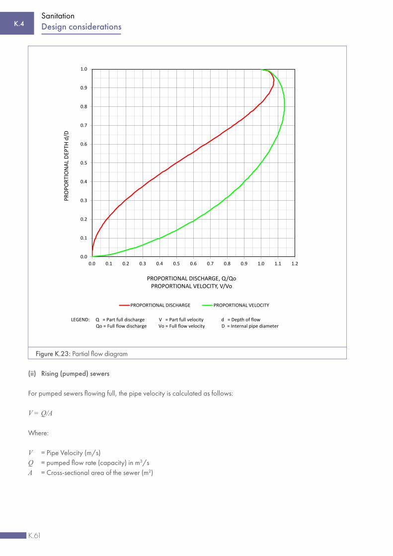
K.61
Sanitation
(ii) Rising (pumped) sewers
For pumped sewers flowing full, the pipe velocity is calculated as follows:
V = Q/A
Where:
V = Pipe Velocity (m/s)Q = pumped flow rate (capacity) in m3/sA = Cross-sectional area of the sewer (m2)
0.0
0.1
0.2
0.3
0.4
0.5
0.6
0.7
0.8
0.9
1.0
0.0 0.1 0.2 0.3 0.4 0.5 0.6 0.7 0.8 0.9 1.0 1.1 1.2
PRO
PORT
ION
AL D
EPTH
d/D
PROPORTIONAL DISCHARGE, Q/QoPROPORTIONAL VELOCITY, V/Vo
PROPORTIONAL DISCHARGE PROPORTIONAL VELOCITY
LEGEND: Q = Part full discharge V = Part full velocity d = Depth of flowQo = Full flow discharge Vo = Full flow velocity D = Internal pipe diameter
Figure K.23: Partial flow diagram
K.4 Design considerations

K.62
Sanitation
For circular sewers it is calculated as follows:
A = π Ø2/4
Where Ø = pipe diameter (m)
K.4.3.3 Gravity sewer system
The following design criteria are recommended for gravity sewers:
(i) Gravity main – minimum and maximum flow velocities and gradients
Sewers may follow the general slope of the ground, provided that a minimum full-bore velocity of 0.6-0.7 m/s is maintained at the minimum gradient in all gravity mains. This is to ensure that sufficient scouring of the mains takes place.
The maximum flow velocity under full-flow conditions should be not more than 2.5 m/s to prevent damage to the pipelines, although a higher flow velocity of up to 3.5 - 4.0 m/s may be acceptable over short pipe lengths and for short periods. The maximum pipe velocity should be checked with the pipe manufacturer. Too high velocities should be avoided due to separation and abrasion.
Table K.18 shows absolute minimum gradients for different diameter pipes required to achieve the minimum full-bore velocity of 0.65 m/s. If flatter grades and lower velocities are considered, it is essential that a detailed cost-benefit study be conducted. The cost of the regular, systematic maintenance and silt/sand removal that will be required when flatter grades and lower velocities are used, will need to be compared to the additional capital cost required to maintain the above minimum grades at full-bore velocity of 0.6 - 0.7 m/s.
The diameters in Table K.15 are for illustrative purposes only. The actual Manning coefficient of the pipe should be obtained from the pipe manufacturer to calculate the minimum gradient to achieve the required minimum velocities of 0.65 m/s.
Table K.15: Minimum gradients for ±0.65 m/s full flow velocity (more than 21 units#1)
Pipe diameterClass
Material (general)
Minimum gradient #1 (Manning n = 0.012)
Flow
Nominal (mm)
Outside (mm)
Inside (mm)
@ 70% (L/s)
110 110 104 34 uPVC 1 : 120 4
160 160 151 34 uPVC 1 : 200 8
200 200 188 34 uPVC 1 : 250 13
250 250 235 34 uPVC 1 : 350 20
315 315 297 34 uPVC 1 : 500 32
355 355 334 34 uPVC 1 : 600 40
450 533 416 100D Concrete 1 : 700 51
525 616 534 75D Concrete 1 : 800 62
600 699 611 75D Concrete 1 : 1 100 103
675 787 685 75D Concrete 1 : 1 300 136
K.4Design considerations

K.63
Sanitation
Table K.15: Minimum gradients for ±0.65 m/s full-flow velocity (more than 21 units#1)
Pipe diameterClass
Material (general)
Minimum gradient #1 (Manning n = 0.012)
Flow
Nominal (mm)
Outside (mm)
Inside (mm)
@ 70% (L/s)
750 870 762 75D Concrete 1 : 1 500 171
825 946 830 75D Concrete 1 : 1 800 208
900 1 041 913 75D Concrete 1 : 2 000 247
1 050 1 194 1 066 50D Concrete 1 : 2 300 297
1 200 1 365 1 219 50D Concrete 1 : 2 800 407
1 350 1 524 1 372 50D Concrete 1 : 3 400 529
1 500 1 689 1 523 50D Concrete 1 : 4 000 668
1 650 1 878 1 700 50D Concrete 1 : 4 600 823
1 800 2 019 1 803 50D Concrete 1 : 5 300 1 028#1 When the number of upstream units exceeds 21, the minimum slope as provided above should be used for the
corresponding diameter when assuming the Manning coefficient is 0.012. For pipes servicing fewer than 21 units, the gradients as shown in Table K.16 should be used.
The sewer pipes should have a steeper gradient closer to the upper end of the sewer network to ensure the pipes are cleared and that settlement is avoided, as the pipes do not flow full regularly and low-flow conditions can occur (depth of flow less than 20% of the diameter). Minimum gradients based on the number of upstream units are listed in Table K.16 to ensure sufficient pipe flushing. House connections should be laid at a minimum slope of 1:60 for 110 mm nominal diameter pipes.
Table K.16: Preferred and minimum gradients for upper end of sewer network (less than 21 units)
Number of units110 mm – Nominal diameter 160 mm – Nominal diameter
Preferred gradient Minimum gradient Preferred gradient Minimum gradient
1 to 10 1 : 60 1 : 75 1 : 80 1 : 100
11 to 20 1 : 75 1 : 100 1 : 100 1 : 140
21 and more 1 : 90 1 : 120 1 : 120 1 : 200
(ii) Gravity main – minimum size/diameter
The minimum permissible diameter for gravity sewer pipes in a municipality should be at least 150 mm inside or nominal diameter, but the absolute minimum diameter of the pipe in sewer reticulation should be 100 mm (connec-tions to properties).
A minimum pipe diameter of 200 mm (outside) is recommended for CBD developments. This is to provide some spare capacity for future densification, because of the difficulty of installing additional services in the CBD.
K.4.3.4 Pumped sewer system
Sewer pumping stations should only be considered where absolutely necessary, and where a gravity alternative is not feasible. A sewer pump station should consist of a sump to receive incoming sewage, and pumps that pump the sewage through a rising main into a downstream stilling chamber. The design recommendations for each of these four components are provided below.
K.4 Design considerations

K.64
Sanitation
(i) Sizing of sumps
The sump receives the sewage flow and acts as a storage vessel from where sewage is periodically pumped. The sump comprises an active and emergency storage volume. The active volume is defined by the operating levels of the sump. The emergency storage volume provides additional safety when the pumps fail, in that it provides time for the maintenance crew to make repairs before an overflow happens. The calculation of the emergency and active sump volume is detailed below.
a. Emergency storage
A minimum emergency storage capacity should be provided representing a capacity that is equivalent to four to six hours’ flow at the design flow rate, over and above the capacity available in the sump at normal top-water level (i.e. the level at which the duty pump cuts in). This provision applies only to pump stations serving less than 250 dwelling units and where no backup power for pump stations is supplied. The aim is to contain any sewage spillage.
For pump stations serving larger numbers of dwelling units, the sump capacity should be subject to special consid-eration, in consultation with the local authority concerned. Emergency storage may be provided inside or outside the pump station. Emergency sump volume is calculated using the following formula:
VE = q × TE
Where:
TE = minimum emergency storage time (specified by local authority – generally 4 to 6 hours)q = average raw sewage inflow rate (ADDWF)VE = sump emergency storage volume (m3)
Some emergency storage capacity might also be available in the up-stream gravity lines and manholes.
b. Active sump volume
Active sump volume is calculated using the following formula:
T = VA
– VA
q (Q – q)
Where:
T = Minimum cycle between pump starts (time to fill + time to empty)VA = Sump active volume (m3/s)Q = Pumping rateq = Sewage inflow rate
The total sump volume is the sum of the active and emergency volumes:
V = VA + VE
K.4Design considerations

K.65
Sanitation
c. Buoyancy calculations
Ensure that the structure will not float when subjected to high groundwater levels.
(ii) Sizing of pumps
Pumps are mechanical equipment used to transfer sewage from the sump to a higher location within the sewer system. The selection of the pumps depends on the hydraulic requirements they must meet and the level of safety the design requires.
a. Design flow
The capacity of the pumping station should equal or exceed the instantaneous peak wet weather flow (IPWWF) that arrives at the pumping station to allow for stormwater ingress. In the case of a 30% stormwater allowance, the pump should have a capacity equal to the design flow, generally:
IPDWF =
IPDWF = 1.43 × IPDWF(1– 0.3) 0.7
b. System hydraulics
The pumping station should be designed to operate under the full range of projected system hydraulic conditions. The system should be designed to prevent a pump from operating for long periods of time beyond the pump manufacturer’s recommended normal operating range. Start/stop cycles should not exceed the pump motor manufacturer’s recommendation.
The pump station should be designed in such a way that the pumps operate a maximum of two duty cycles per hour during average flow conditions and not more than six cycles per hour during instantaneous peak wet weather flow.
c. Efficiency
Pumps should be selected to ensure that the operating point is near the maximum efficiency point on the pump performance curve, within the pump’s recommended operating range, and within the manufacturer’s recommended limits for radial thrust and vibration.
d. Standby pumps
Pumping stations should be designed to accommodate instantaneous peak wet weather flow (IPWWF), with at least one reserve pump. At least two pumps should be installed, each capable of pumping at a flow rate more than the peak wet weather flow (for emergency purposes), but at the same time, taking care not to provide excessive standby capacity. The standby pump should come into operation automatically if a duty pump or its driving motor fails.
Where three or more pumps are selected, they should be designed to fit actual flow conditions and must be so designed so that with any one pump out of service, the remaining pumps will have the capacity to pump the IPWWF. Pumps should be designed in such a way that one pump can empty the sump plus handle the average inflow in less than 30 minutes.
K.4 Design considerations

K.66
Sanitation
e. Hydraulic influence of pump stations
Although sewer pump stations operate intermittently, their flows can influence the hydraulics of the downstream pipes at any time during the day. It is therefore advised to model the pumps as ‘continuous’ pumps that pump for 24 hours per day when sizing downstream gravity sewers.
f. Surge analysis
Consider hydraulic surges and transients (water hammer) during the design of pump stations and pumping mains.
g. Cavitation
Ensure that the Net Positive Suction Head (NPSH) available is higher than the NPSH required to avoid cavitation damage to the pump.
h. Backup power for pump stations
Emergency power supply should be provided to pumping stations to ensure continuous operation when primary electrical supply is out of service (standby generator). Larger pump stations should have permanent diesel-oil-fuelled, engine-driven generator units with automatic transfer switches to transfer the electrical feed from the primary to the standby unit when a power failure is detected by the instrumentation and control system, sized to operate all electrical components. For smaller pump stations, where a dedicated backup generator is not available, a portable generator should be available. A manual transfer switch and an emergency plug-in power connection to the station, for use with the portable generator, should in these cases be installed. A standby generator should be provided to supply the pump station with full load power for at least 6 hours.
i. Pump sizing and design
The appropriate pump should be selected by considering the pump system curves. The pump system curves indicate the interaction between the pump performance and the pumping main used to deliver the discharge. The pumping system curves should be determined in the selection of the pumps to ensure an appropriate and efficient pumping system.
Every pump manufacturer has a pump performance curve for every pump. The pump performance curve shows the discharge relative to the pressure for a particular pump and impeller size (diameter). It also shows the efficiency, as illustrated below. The system curve (which represents the static head and the friction losses of the pumping main) should be used in conjunction with the pump performance curve to specify the most appropriate pump that can accommodate the flow and provide the required head at the desired efficiency. The operating (duty) point is where the pump performance curve and system curve intersect. The duty point should be near the pump’s best efficiency point (BEP), as is shown in Figure K.24.
K.4Design considerations

K.67
Sanitation
Figure K.24: Pumping system curve
The following should be considered when selecting the correct pump:
• The pump should be selected to ensure that the duty specified falls well within the stable range of the head/quantity characteristic curve of the pump.
• The pump should have a non-overloading power curve.• Maximum suction lift should not exceed the pump manufacturer’s recommendations and should be based on a
net positive suction calculation with an allowed factor of safety.
(iii) Rising mains
Rising mains should be designed to take care of the following:
• Minimum and maximum flow velocities: The minimum velocity of flow in a rising main should be 0.6 m/s. Flow velocities must be limited to protect pipeline coatings and reduce the effects of water hammer. The preferred maximum allowed is 1.5 to 1.8 m/s, but an absolute maximum of 2.5 m/s is acceptable where only intermittent peak flows occur.
• Minimum size/diameter: The minimum internal diameter of a rising main should be 100 mm, except where a macerator system is used, in which case the diameter can be reduced to 75 mm.
Other issues to consider when designing a rising main include:
• Where possible, the rising main must have a positive grade with no low points or high points so as to avoid possible gas release and grit deposition.
• Scour valves and air valves must be avoided at all cost.• Protect the pipeline against hammer and surge forces (analyse and provide protection).• Turbulence must be avoided to prevent the release of H2S gas at the outlet.• Provide protection against unbalanced forces (thrust) where necessary (thrust blocks and support).
K.4 Design considerations
Pump curve
System curve
Pumpefficiencycurve
Actual pumpefficiency obtained
Pump curveduty point
Rate of flow
Hea
d

K.68
Sanitation
(iv) Stilling chambers
Stilling chambers should be provided at the heads of all rising mains, and should be designed so that the liquid level always remains above the soffit level of the rising main where it enters the chamber. Stilling chambers should preferably be ventilated.
K.4.4 General design guidelines for waterborne sanitation systems
K.4.4.1 Sewer pipes
(i) Location
Sewers should be sited to provide the most economical design, taking into account the topography (i.e. in road reserves, servitudes, parks, other open spaces, etc.). The minimum clear width to be allocated to a sewer in the road reserve should be 1.5 m.
a. Siting
Sewer pipes should be located in open areas, road reserves or municipal land where they may be easily accessed at all times, preferably on the lower side of the road. In road reserves, sewers should be installed between the stormwater drain and the plot boundary where applicable. In built-up areas, sewer pipes should preferably be located 1.2 to 1.5 m from the plot boundary. The positioning of infrastructure in municipal areas is often guided by municipal specifications and standards.
Mid-block sewers should be avoided as far as practically possible. Where the mid-block system is unavoidable, the sewer connections should not be installed deeper than 2 m and the main sewer should not be installed deeper than 3 m. If these depths are to be exceeded, a double system must be used. In cases where decision-making is difficult, a comparative estimate of costs with the double system must be made. When designing a double system, it is essential that close attention is paid to where other services, particularly stormwater drains, are crossed. Special permission is required for mid-block sewers if they cannot be avoided. Mid-block sewers are not recommended in townships with individual stands of less than 400 m2 in area. The following aspects should be considered when routing sewers:
• The sewer should follow the natural fall of the ground• The sewer should be laid next to those properties that will benefit most directly from the sewer• Road crossings should be kept to a minimum• All other municipal services should be taken into account when installing a new sewer• There should be minimum interference with existing structures
b. Road crossings
Where a road crossing is unavoidable, consider using the following:
• Existing crossings, such as culverts and bridges, to avoid excavation and pipe jacking for ground crossings.• Pipe jacking where applicable and acceptable.• Encasement of sewers that cross under surfaced roads (existing tar roads) in concrete.
K.4Design considerations

K.69
Sanitation
• Backfilling of trenches in accordance with relevant construction specifications. (The selected materials should be hand-compacted to a depth of at least 300 mm above the top of the pipe).
c. Dolomitic regions
The following publications can be consulted regarding dolomitic areas:
• Appropriate Development Infrastructure on Dolomite: Manual for Consultants, Volume 1 and Volume 2, PW34454
• Section 2.8 of Part 1 of the Home Building Manual as published by the National Home Builders’ Registration Council (NHBRC)55
• Proposed method for dolomite land hazard and risk assessment in SAICE Journal56
(ii) Minimum depth and cover
Table K.17 provides the recommended minimum values of cover to the outside of the pipe barrel for main sewers.
Table K.17: Minimum values of cover for pipe locations
Pipe location Cover
House connections 300 – 800 mm
Public open spaces and mid-blocks (servitude) 800 – 1 000 mm
Street reserve (sidewalks) 1 100 – 1 200 mm - below final kerb level
Roadways (trafficked areas) 1 200 – 1 400 mm - below final constructed road level
The combination of loading, pipe depth, pipe strength, and bedding type should be acceptable to the relevant authorities. Shallower depths can be used where the bedding and compaction are well controlled, especially in roadways. Depths of cover for house connections should be such that the pipelines are not compromised by ex-cess loading. Lesser depths of cover may be permitted, subject to integrated design of all services, including trunk services allowed for in development plans. However, where the depth of cover in roads or sidewalks is less than 600 mm, or in servitudes less than 300 mm, the pipe should be protected from damage by the following options:
• The placement of cast-in-situ or precast concrete slab(s) over the pipe, isolated from the pipe crown by a soil cushion of 100-150 mm minimum thickness. The protecting slab(s) should be wide enough and designed to prevent excessive superimposed loads being transferred directly to the pipes (see Figure K.25).
or
• The use of structurally stronger pipes that are able to withstand superimposed loads at the depth concerned.
or
• In isolated cases, the placement of additional earth filling over the existing ground level where this is possible.
K.4 Design considerations

K.70
Sanitation
(iii) Trenching, bedding and backfilling
The trenching, bedding and backfilling for all sewers should be in accordance with the requirements of the relevant SABS standards and the local municipal requirements. A structural design of the pipe and bedding structure should be done where trenches are
• located under roads,• deeper than 3 m, and/or• other than those classified as ‘narrow’ (i.e. where overall trench width is greater than nominal pipe diameter
– d + 450 mm for pipes up to 300 mm diameter).
The typical acceptable trench widths per outside pipe diameter are given in Table K.18.
Table K.18: Trench widths
Outside diameter (mm) Trench width on each side of the pipe (mm)
<125 300
126 – 700 300
701 – 1 000 400
1 001 – 2 000 500
2 001 + 600
Pipes should be laid according to approved methods on the specified bedding to ensure trueness to line and level, and in such a manner that the barrels of pipes bear evenly on the bedding over their full length.
Spigot-and-socket pipes should be placed with the socket facing upstream. Pipes and joints should be laid in accordance with the manufacturer’s instructions.
Pipes of 600 mm in diameter and larger should be kept clean on the inside by being swept by hand as laying progresses. The open ends of the pipelines should be closed at all times using approved plugs when laying is not in progress.
Figure K.25: Protection of pipes at reduced depths of cover (e.g. Class B bedding)
K.4Design considerations
Concrete slab(s)Less than:(i) 300 mm in
servitudes(ii) 600 mm in
road reserves
100 mmmin
Fill
Compacted selected fill blanket
Beading cradle
K.71
Sanitation
During all pipe-laying and bedding operations, care should be taken to prevent the entry of any dirt or concrete into the flexible pipe joints by sealing the joint with clay or other approved means.
The selected bedding and backfill material should be compacted to an optimum moisture content of at least 90% of modified AASHTO density.
After a pipeline has been laid, tested and approved, the trench should be partly backfilled (with hand implements), to a height of 300 mm above the top of the pipe barrel. Use suitable backfill material that contains sufficient fine material to ensure a densely graded, well-compacted backfill, but is free from stones exceeding 20 mm, organic matter, and lumps of clay exceeding 75 mm. Backfilling around and over the pipeline should be in layers not exceeding 100 mm compacted thickness. Backfilling should be carried out simultaneously and equally on both sides of the sewer to avoid unequal forces being exerted.
(iv) Anchoring – steep slopes
Concrete anchor blocks should be provided where grades are steeper than a ratio of 1:10 (or as otherwise required by the relevant local authority standards).
(v) Curved alignment
A straight alignment between manholes should normally be used, but curvilinear, horizontal or vertical alignment may be used where the economic circumstances warrant it, subject to the following limitations:
• The minimum radius of curvature is 30 m.• Curvilinear alignment may be used only when approved flexible joints or pipes are used.• In the construction of a steep drop, bent fittings may be used at the top and bottom of the steep short length of
pipe, thus providing a curved alignment between the flat and steep gradients.
(vi) Encased pipes
The pipe can be encased for structural support or where the pipe is installed underneath a road (only where a slab has not been cast to support the pipe). Depression in the road should be prevented by ensuring the pipe does not deform under load. Where encasement is unavoidable, it should be made discontinuous at pipe joints in order to maintain joint flexibility.
(vii) Pipe load and deflection calculations
When designing pipe loads, it is important to investigate the loading (soil and imposed) on the pipe and any possible deflection. The calculations are dependent on the rigidity of the pipe.
• For flexible pipes (i.e. PVC pipes), the resultant deflection should be calculated for the applied loading conditions (soil and live load) and checked against manufacturer’s allowable deflection.
• For rigid pipes (i.e. concrete), the applied load (soil and live load) should be calculated and checked against the load-carrying capacity tolerances as specified by the manufacturer.
The loading on the pipe is not only dependent on the rigidity of the pipe, but also on the trench and the bedding. This Guide is mainly concerned with the hydraulic design and planning of sewers. Other design guidelines – such
K.4 Design considerations

K.72
Sanitation
as SANS 120057, SANS 67658, SANS 67759, and SANS 1010260 – should be consulted for more details on pipe design and installation.
K.4.4.2 Manholes
(i) Location and spacing
The maximum distance between manholes on either straight or curved alignments should be as follows:
• 100 to 150 m where the municipality concerned has power-rodding machines and other equipment capable of cleaning the longer lengths between manholes (rod length generally <80 m). This should be confirmed with the municipality.
• 100 m where the municipality concerned has only hand-operated rodding equipment. The municipality’s guidelines should be referred to for details regarding spacing.
• This distance must be decreased on steep grades so that the pressure head on any part of the sewer does not exceed 6 m under blockage conditions.
• On collector sewers, and especially outfall sewers, the distance between manholes may be increased.
Note: Consider the costs involved in acquiring power-cleaning equipment in order to permit a greater manhole spacing, especially in areas prone to theft and vandalism that can lead to blockages and higher maintenance cost.
Manholes should also be placed in the following circumstances:
• At all junction points where main sewers meet (not every plot connection)• At all changes of gradient• At all changes in direction – except in the case of curved alignment and at the top of shallow drops• Where there is a change in pipe diameter in outfalls (pipe soffits must be equal)• Where two or more sewer lines connect• At positions on steep grades (1:10 or steeper), to prevent backpressure in house gullies under blockage
conditions• At the higher end of all sections that serve more than three dwelling units and that are longer than 50 m• At least one manhole within the road reserve where sewers cross a road
Where manholes have to be constructed within an area that would be inundated by a flood of 50 years’ recurrence interval, they should be raised so that the covers are above this flood level.
It is advisable to place gullies away from where stormwater flows or collects. The number of gullies should be limited, if practical.
Where the sewer and water lines are to be installed in the same trench, sewer manholes should be positioned to allow for a minimum clearance distance of 500 mm between the outside of any manhole and the water pipeline.
K.4Design considerations

K.73
Sanitation
(ii) Types
Six types of standard manholes are presented in Table K.19.
Table K.19: Manhole types
Type Description
Types I, MA and MB
These manholes are used in conjunction with sewer pipes with a diameter of 300 mm and smaller.
Type III This manhole is similar to types I, MA and MB, but is constructed of precast concrete sections.
Type Z This manhole is used in conjunction with pipe diameters from 375 mm up to and including 600 mm and is constructed from cast-in-situ class 20/19 concrete. The roof slab is provided with a 225 mm diameter hole for the fitting of a ventilation pipe.
Type Y This manhole is similar to type Z, except that it is used on pipelines exceeding a diameter of 600 mm.
As types Y and Z manholes are not used at pipeline junctions, special manholes should be used. Relevant design standards should be sought for non-standard structures such as manholes for in-situ sewers, metering structures, and inlet and outlet structures.
(iii) Sizes
The minimum internal dimensions of manhole chambers and shafts are shown in Table K.20.
Table K.20: Minimum internal dimensions of manhole chambers and shafts
Shape Chamber Shaft
Circular 1 000 mm 750 mm
Rectangular 910 mm 610 mm
The minimum height should be 2 m from the soffit of the main through the pipe to the soffit of the manhole chamber roof slab, before any reduction in size is permitted. Manholes deeper than 3 m should be a minimum of 1.5 m in diameter.
(iv) Benching
An area of benching should be provided in each manhole so that a person can stand easily, comfortably and without danger, while working in the manhole. Channels and benching should be shaped correctly and carefully to minimise any possible turbulence.
Manhole benching should have a grade not steeper than a ratio of 1:5, nor flatter than 1:25, and should be battered back equally from each side of the manhole channels such that the opening at the level of the pipe soffits has a width of 1.2 d, where d is the nominal pipe diameter.
The in-situ casting for channelling and benching in manholes and adjoining culverts should be rendered in 25 mm thick granolithic concrete and finished smooth and true with a steel trowel and rounded at corners and edges. The benching should be taken to 25 mm above the highest pipe soffit.
K.4 Design considerations

K.74
Sanitation
(v) Pipes entering a manhole
After the manhole foundation slab has been cast, the semi-circular channels and fittings suitable for the type of pipe laid should be placed in position and embedded in the concrete benching. The sockets of channels and the space between two abutting channels should be filled with a 1:1 cement : sand mortar mix, well worked in, and all joints should be neatly finished off.
Pipes entering manholes should be cast into position in the benching to ensure a watertight joint between the pipe and the manhole. Caulking should only be allowed where a pipe is built into an existing manhole.
The pipes built into manholes, or culverts adjoining large manholes, should be encased in concrete after the walls have been completed, and the sewer should be jointed in such a way that the pipes produce a flexible joint on each side of each manhole or culvert.
(vi) Design of manholes
All manholes, including the connection between manhole and sewer, should be designed in accordance with the requirements of industry standards, such as SABS 1200 LD Sewers, Standardized Specification for Civil Engineering Construction.61 Where manholes are of cast-in-situ concrete, chambers, slabs and shafts should be structurally designed to have a strength equivalent to a brick or precast concrete manhole.
For manholes located in road reserves, spacer rings or a few courses of brickwork should be allowed for between the manhole roof slab and the cover frame to facilitate minor adjustments in the level of the manhole cover. Adjustable manhole frames may also be used.
Heavy-load type manholes should be used in trafficked areas and medium-load type manholes everywhere else.
(vii) Steep drops
Steep drops should be avoided wherever possible. Where a steep drop is unavoidable (e.g. to connect two sewers at different levels), use should be made of a steep, short length of pipe connected to the higher sewer by one or more 22.5 degree bends and to a manhole on the lower sewer also by one or more 22.5 degree bends, as shown in Figure K.26.
K.4Design considerations

K.75
Sanitation
(viii) Backdrop manholes
A backdrop and/or ramp junction manhole should not be used in sewer systems. Where flows and economy considerations (e.g. trench depth) become significant, the alternative of two closely spaced manholes or lamp holes, or a combination of these, is the prescribed option.
(ix) Elevation drop through manhole
The minimum slope in any manhole from the inlet pipe to the outlet pipe in a straight line (elevation drop through the manhole) is the greater of
• 50 – 80 mm, or• the slope of the inlet pipe, or • the slope of the outlet pipe.
This drop through the manhole is to minimise energy (hydraulic) losses. Where there is a change of direction in a manhole, the minimum height difference between inlet and outlet pipes should be increased to allow for the loss of energy around the bend. Table K. 21 gives an indication of the fall in manholes (mm), for various bends and pipe sizes up to 300 mm.
Table K.21: Fall in manholes for various bends and pipe sizes
Diameter (mm) 150 250 300
Angle (degree) 0⁰ 22.5⁰ 45⁰ 90⁰ 0⁰ 22.5⁰ 45⁰ 90⁰ 0⁰ 22.5⁰ 45⁰ 90⁰
Gra
dien
t
1:20 60 79 98 136 60 79 135 210 60 108 156 251
1:30 40 53 65 90 40 65 90 140 40 72 104 168
1:40 30 39 49 68 30 49 67 105 30 54 78 125
1:50 24 32 39 54 24 39 54 84 24 43 62 100
1:60 20 26 33 45 20 32 45 70 20 36 52 84
1:70 17 22 28 39 17 28 38 60 17 31 44 72
1:80 15 20 24 34 15 24 34 52 15 27 39 63
Figure K.26: Steep drops in sewers
K.4 Design considerations
Manhole
Pipes on firmgranular bedding
One or more 116 bends

K.76
Sanitation
For larger diameter pipes (>300 mm), the standard energy equation should be used for calculating the drop. Also, for gradients steeper than 1:15, the actual drop through the manhole, plus 25 mm, must be provided.
hb = kb vf
2
2g
Where:
kb = Energy loss coefficient (see Table K.22)vf = Velocity in pipe at full-flow conditions (m/s)hb = Energy loss (m)
Table K.22: Energy loss coefficients
Angle (degree) Energy loss coefficient (kb)
0 – 22.5 0 – 0.1
22.5 – 45 0.1 – 0.2
45 – 90 0.2 – 0.4
(x) Turbulence and odour prevention
Turbulence at junctions and in manholes may cause bad odours, which must be reduced to a minimum by doing the following:
• Limit the number of connections to interceptor sewers.• Avoid situations that may lead to hydraulic jumps, such as ramps and sudden changes from steep to flat grades
– where one grade is five or more times flatter than the other grade in the mains.• Shape channels and benching in manholes carefully and correctly.
(xi) Watertightness
Provide for the sealing of manholes for watertightness with an approved sealant to prevent ingress of stormwater. Joints should be caulked with a waterproofing compound. The outside of the joint should be wrapped with a sealing tape.
(xii) Vandalism and theft
Consider the risk of vandalism and theft when selecting the manhole cover material and lid type, to reduce or eliminate the risk of manhole lids being removed or damaged.
K.4.4.3 Sewer connections
(i) Plot connections
The following should be considered when designing plot connections:
K.4Design considerations

K.77
Sanitation
• Connections should be a minimum of 100 mm internal diameter. • It is acceptable to have direct connections to 150 mm pipes in residential areas. Connections to sewers of
more than 150 mm diameter are only allowed through manholes. It is advisable to have industrial connections directly into a manhole on the sewer main. An inspection chamber should be constructed on the property boundary for commercial park developments upstream of the manhole where the connection is made.
• Unused plot connections should be terminated with a suitable watertight stopper on the boundary of the plot, or the boundary of the sewer servitude, whichever is applicable.
• Locate the connecting sewer deep enough to drain the full area of the plot portion on which building construction is permitted (minimum of 80% of the total plot area).
• The sewer connection should ideally be provided at the lowest suitable point on the plot.• Consult the municipality for guidance with multi-plot connections.
Exceptions to the above-mentioned considerations are the following:
• In special residential areas, where a plot extends for a distance of more than 50 m from the boundary where the connecting sewer is laid, provision needs only be made to drain the area of the plot within 50 m of this boundary.
• School sites should be carefully evaluated with regard to the position, diameter and depth of the connection(s) provided.
• Where detailed development proposals are submitted for subdivided plots as group schemes, one connecting sewer may be provided to serve such group of plots.
(ii) Road crossings
House connections crossing a road should be avoided. Where it is possible to connect two plots at a time via a single-sewer road crossing (which is the preferable option), the two plots should connect via a lamp hole onto the 160 mm diameter sewer road crossing.
Where plots have to be connected to a sewer on the opposite side of a street, consideration should be given to the economics of providing 100 mm diameter sewer branches across the road to serve the connecting sewers from two or more plots.
(iii) Depth and cover
The recommended minimum values of cover to the outside of the pipe barrel for connecting sewers are as follows:
• Servitudes: 600 – 800 mm• Road reserves: 1 000 – 1 100 mm
(iv) Invert level
In the design of sewers, consider the final finished levels of carriageways, sidewalks and vehicle entrances to properties, and the depth of sewer inverts below finished sidewalk levels, particularly for steep crossfalls. The invert levels indicated at a manhole location should be the levels projected at the theoretical centre of the manhole by the invert grade lines of the pipes entering and leaving such manhole. In cases where branch lines with smaller diameters enter a manhole, the soffit levels of these branch lines should match those of the main branch line. However, in areas where pipes are laid to minimum grades, this practice may need to be relaxed. The slope of
K.4 Design considerations

K.78
Sanitation
the manhole channel should be as required to join the invert levels of the pipes entering and leaving the manhole without allowing any additional fall through the manhole chamber.
When designing the invert depth of the main sewer to ensure that all the plots can drain to it, the fall required from ground level at the head of the house drain to the invert of the main sewer at the point where the connecting sewer joins the main sewer should be taken as the sum of the following components:
• 400 - 450 mm to allow for a minimum cover of 300 mm at the head of the house drain, plus 100 - 150 mm for the diameter and thickness of the house drain
• The fall required to accommodate the length of the house drain and the connecting sewer, assuming a minimum grade of 1:60 and taking into account the configuration of the plot and the probable route and location of the house drains
• The diameter of the main sewer
In the case of very flat terrain, and where the house drains may be laid as an integral part of the engineering services, flatter minimum grades than 1:60 for the house drains may be considered. This relaxation could also be applied to isolated plots that are difficult to connect, or the ground in such plots could be filled to provide minimum cover to the drains.
Except where the depth of the existing infrastructure dictates otherwise (depending on the invert level of the existing sewer), the minimum depth to the invert of a sewer connection is as follows:
• Mid-block: 1.2 m• Road reserve: 1.5 m
The depth of interceptor sewers should be at least 0.6 m deeper than calculated theoretically, starting from a high point on the sewer. The highest possible invert level of the municipal sewer (HILS) at the plot connection point may be calculated as follows:
HILS = LGL – 0.3
– L – Ø 60
Where:
LGL = Minimum ground level on the plot (to enable drainage of even the lowest point of the plot)0.3 = Minimum cover required at the head of the plot connectionL = Length of the plot connectionØ = Diameter of municipal sewer (to enable soffit-to-soffit connection)
The following formula and Figure K.27 can also be used to calculate the depth of the invert of the sewer-house connection:
Invert level at B = ZA – 0.4 – (L1 + L2)
– 0.5 60
K.4Design considerations

K.79
Sanitation
Where:
ZA = Ground level at AZB = Ground level at BL1 and L2 = Maximum length of private sewer (house connections)DB = Depth of sewer at point B0.4 m = The minimum depth at the extremity of any house drain (0.3 m cover and 0.1 m is the diameter of a
drainpipe)0.5 m = 0.5 m for the junction at the municipal sewer1/60 = 1:60 is the minimum gradient of a house connection
Figure K.27: Diagram of the depth of the invert of the sewer-house connection
(v) Junction with the main sewer
A plain 45⁰degree junction should be used at the point where the connecting sewer joins the main sewer, with the junction leg pointing upwards at an angle. Saddles should not be permitted during initial construction.
The junction with an interceptor sewer should preferably be soffit-to-soffit. Due consideration should be given to the hydraulic energy lines when designing junctions. A 0.5 m invert depth should be allowed for the junction at the municipal sewer.
K.4.4.4 Pump stations
(i) Location and siting
The location and siting of pump stations should meet the following requirments:
• Result in minimum impact (incidence and effect) on the environment (pollution), especially regarding wastewater overflows
• Minimise any community impact and be as far as possible from any future/present residential areas• Minimise inconvenience to those using it, as well as those operating and maintaining it
K.4 Design considerations
L1
B
A
Municipal sewer line
L2

K.80
Sanitation
• Minimise impact in the event of something going wrong• Be outside the 1:50-year flood line
(ii) Safety precautions
Safety precautions in accordance with the relevant legislation and by-laws should be incorporated in the design of all pump stations, and in particular in the precautions referred to in the Factories, Machinery and Building Work Act, 1941 and the Occupational Health and Safety Act, 1993.
(iii) General physical design considerations for pump stations
The following aspects should be taken into account in the design of a pump station:
• Pumps (impeller and casing ports) should be designed to allow solids to pass through and be non-clogging and non-ragging. The impellers should be able to pass solids of up to 75 mm in diameter. Impeller size should be chosen based on the expected requirement of solids handling. Some discharge port sizes and particle sizes are provided in Table K.23.
Table K.23: Discharge port sizes and particle sizes
Size of discharge port Particle size
Up to 100 mm 75 mm
150 – 300 mm 100 mm
300 mm + 150 mm
• Gate valves should be provided for isolation and maintenance purposes• Non-return valves should be provided on the delivery pipework• Drainage of water within the pump station needs to be accommodated• The pump station should be readily accessible during all weather conditions and have adequate space for
maintenance and operation (turning and working space)• The pump station should be fenced for protection against theft and for the sake of public safety• Opportunity to service, remove and replace all major equipment (pumps, motors, electrical panels, valve and
surge control components) must be considered in the design• Appropriate design measures should be taken to control noise and odour• Adequate protection measures should, where necessary, be provided at the inlets to pump stations for the
protection of the pumping equipment against large solids in the effluent• Re-priming of pumps should be considered in the design of pump stations
(iv) Sump
The following aspects should be taken into account in the design of a pump sump:
• Equipment and fixtures in the sump should be corrosion proof (stainless steel, unless otherwise specified and approved).
• Sumps should be designed to minimise solid build-up and be self-cleaning. Trench- or hopper-style sumps should be used (with side slopes of between 45 degree and 60 degree or steeper), sloping to the inlet of the
K.4Design considerations

K.81
Sanitation
pumps. Lower angles may be used if there is strong flow. Maintenance and cleaning procedures should be accommodated in the design to remove any solids that build up in the sump.
• Care should be taken in the design of pump stations to avoid flooding of the dry well and/or electrical installations by stormwater or infiltration.
• Adequate protection, where necessary, in the form of screens or metal baskets, should be provided at the inlets to pump stations for the protection of the pumping equipment.
• The sump should be well-ventilated and adhere to relevant safety legislation to ensure the safety of personnel in the presence of dangerous gas formation.
• The sump should be designed to avoid air entrainment and low local velocities.
(v) Automated control in pump stations
Sewer pump stations should be fitted with automatic pump controls. At a given water level, the first pump should be activated, and if the water level rises higher, the other pumps should be activated one by one. In cases where the water level rises extremely high, the standby pump should also be activated. At a predetermined low water level, all pumps must be switched off.
K.4.4.5 Syphons
Syphons, also called sag or inverted syphons, are designed to carry flow across an obstruction (road, river, etc.) where it cannot be achieved by a sewer placed at a continuous grade. Enough pressure head must be available before and after the obstruction.
The individual pressurised pipes or conduits comprising of the syphon are normally smaller in diameter than the gravity system, resulting in higher velocities. The higher velocity serves to keep heavier solids in suspension and prevents deposition of solids.
K.4 Design considerations
Figure K.28: Example of a syphon system
Ada
pted
from
http
://
ww
w.k
ingc
ount
y.go
v 62
Smaller diameter pipe than connecting pipes
Upstream pipe at higher level than downstream pipe
Syphon
Flow
Flow
Obstruction e.g. river

K.82
Sanitation
Syphons should be constructed with multiple pipes to match the pipes in active use with the actual wastewater being conveyed. Syphons should be designed to have three barrels and need to be full flowing to be able to operate. The three pipes should be designed as follows:
• One full-flowing pipe to be able to convey the ADDWF (minimum flow)• Two full-flowing pipes to be able to convey ADDWF up to the PDDWF (average flow)• Three full-flowing pipes to be able to convey the PWWF (above-average flow)
The velocity in each of the syphon pipes should be more than 0.9 m/s. The velocity in the syphon is dependent on the length of the syphon and should be as follows:
• A short syphon (<70 m) should have a velocity of ≤1 m/s• A syphon longer than 70 m and with concrete transition structures at the inlet should have a velocity of 3 m/s
Consider the following when designing a syphon:
• The minimum self-cleansing velocity in the syphon should be obtained during ADDWF, or at least once a day during PDDWF (see Table K.24).
• The velocities in the syphon should range between 1 m/s and 3 m/s, dependent on the available head, economic considerations and the length of the syphon.
• The syphon should not have sharp bends (vertical or horizontal), changes in diameter or be too steep in gradient in the rising leg so as to ensure self-cleaning and not to complicate the removal of heavy solids.
• Hydraulic capacity of the syphon should never be lower than an upstream sewer system.• The minimum diameter of a syphon conduit should be 150 mm.• The friction loss through the barrel should be determined by the design velocity, and additional losses due to
side-overflow weirs and directional changes (bends) should also be taken into account. The bend losses are a function of the velocity head, deflection angle, syphon diameter and radius of the bend curvature.
• As a safety factor, 10% should be added to the head losses calculated.• Blowback should be taken into account in the design, as it can occur where free flow is at the entrance or in
long syphons, as the air becomes entrapped.• Backwater should be taken into account where the losses in the syphon are greater than the difference in the
upstream and downstream water level.
The minimum self-cleansing velocities that need to be achieved for a general medium sediment load (50 mg/L) are given in Table K.24. The length of the syphon should also be taken into account (as given by the criteria above).
Table K.24: Minimum self-cleansing velocities for syphons
Internal pipe diameter (mm) Minimum self-cleansing velocity for a sediment load of 50 mg/L
150 0.68
225 0.86
300 1.02
375 1.17
500 1.39
750 1.78
1 000 2.12
K.4Design considerations

K.83
Sanitation
Table K.24: Minimum self-cleansing velocities for syphons
Internal pipe diameter (mm) Minimum self-cleansing velocity for a sediment load of 50 mg/L
1 250 2.43
1 500 2.72
1 750 2.99
2 000 3.25
To make maintenance easier, the following should be considered during the design:
• Provision of air jumpers for hydrogen sulphide control.• Provision of acid-resistant lining on inlet and outlet structures.• Provision of adequate working space inside the inlet and outlet structures for cleaning the pipe barrels. Verify
the required space for electrical cleaning equipment.• Provision of a cleanout point at the low point of the syphon to enable complete draining (if feasible). Alternatively,
a sump at the inlet end of the syphon can be provided to allow draining of the syphon before cleaning and inspection.
• Pressure-type manholes and covers should be considered when crossing streams so as to prevent river water from flowing into the structures.
K.4.4.6 Special structures
Special structures that can be used in the design of sewer systems, include the following:
• Diversions - Diversion structures, or overflow structures, are required where the flow is diverted from one sewer to another. The diversion can be from one interceptor to another or to a relief sewer.
• Junctions - Junction structures are required when one or more branch sewers join or enter a main sewer and at diversion structures. For large sewers, junctions are usually built in cast-in-place reinforced concrete chambers provided with access points.
• Grit traps - Grit traps operate passively by removing heavy entrained matter from the sewage, reducing the velocity and allowing settling to occur. These traps need to be regularly cleaned to ensure optimal operation.
• Silt traps - Silt traps are designed to trap sand and grit. This is usually achieved by reducing the flow velocity and allowing enough time/distance for the particles to settle and remain in the trap. Depending on the anticipated volume of silt transported in the sewer system, the sizing of the settling bay will in turn determine the number of times it needs to be emptied.
• Ventilation structures - Ventilation structures are required when force draft ventilation is necessary. An air blower can be used at ventilation stations, although it is not always required. In the case of a syphon, consider an airline jumper that connects the inlet and outlet structures. At pump stations or treatment plants, an air blower is usually provided. The fan belt will need to be replaced from time to time and the air fan bearing will require regular lubrication.
• Lamp holes - Lamp holes are the openings constructed on the straight sewer lines between two manholes that are far apart and that permit the insertion of a lamp into the sewer to detect obstructions (if any) inside the sewers from the next manhole. Lamp holes are not constructed as often any more, due to more specialised equipment such as CCTV being available for inspecting sewers.
• Flow-gauging structures - Electromagnetic flow meters, flumes and weirs are used to measure sewage flow. Flow measuring also aids in design and monitoring.
K.4 Design considerations

K.84
Sanitation
K.4.5 Design of wastewater treatment infrastructure
K.4.5.1 Activated sludge and biofiltration treatment systems
The design of activated sludge and biofiltration treatment systems requires expertise and experience. The design aspects and considerations are dependent on the specific inflow characteristics, site conditions and treatment requirements.
K.4.5.2 Pond systems
Although pond systems are regarded as being comparatively less sophisticated than other purification systems, they nevertheless require proper planning, application, design, construction, operation and maintenance. Pond systems use a series of human-made basins in the treatment of sewage. They rely on the natural process to remove suspended solids, soluble organic matter, pathogens and nutrients (nitrogen). Stabilisation or oxidation ponds are classified according to the nature of the biological activity taking place:
• Anaerobic ponds (where the ponds are wholly anaerobic) – these are generally the first ponds in a series of ponds where incoming sewage settles and digests, generally at substantial depth.
• Facultative ponds (where both anaerobic and aerobic conditions exist) – aerobic conditions are encountered in the upper layer of the ponds and anaerobic conditions exist toward the bottom.
• Aerobic or maturation ponds – these ponds are generally shallow and are used mainly for final COD removal and disinfection (which is more effective at shallow depth).
Pond systems could include any combination of the pond types listed. The ponds are always positioned in a sequence of increasing oxygen level.
Both facultative and aerobic ponds derive substantial benefit from high algae concentration levels, as the algae produce large quantities of oxygen in the nutrient-rich water that is used for COD breakdown. As a result of the algal activity, the oxygen levels is generally higher than only allowed for by re-aeration through the surface. The breakdown of COD in turn supplies high levels of CO2, which encourages photosynthesis by the algal population. The effluent discharged from pond systems can in some cases be used for irrigation. Irrigation water quality requirements are prescribed in the General Authorisations in terms of the National Water Act. These requirements are fairly relaxed up to a daily discharge of 500 m3/d, whereafter the requirements exceed those under the General Authorisation for discharge to a water resource. Advanced and augmented pond technologies have to be considered for treatment facilities discharging more than 500 m3/d.
The Water Institute of South Africa (WISA) published the Manual on the design of Small Sewage Treatment Works63 that can be used as an initial guide to the design of pond systems and the WRC published Wastewater treatment technologies – a basic guide.64 More detailed guidance is provided in the following international documents:
• Waste stabilisation ponds65
• ISO 16075-1:2015(en) Guidelines for treated wastewater use for irrigation projects66
• Guidelines for the safe use of wastewater, excreta and greywater – Volume 1: Policy and Regulatory aspects67
• Guidelines for the safe use of wastewater, excreta and greywater – Volume 2: Wastewater use in agriculture68
• Health Guidelines for the Use of Wastewater in Agriculture and Aquaculture69
K.4Design considerations

K.85
Sanitation
K.4.5.3 Package purification plants
Package plants are generally delivered to site by suppliers as a complete unit and generally the design is based on the supplier’s proprietary designs. The design and selection of package plants require specialised knowledge and experience. Authorities can consult Package plants for the treatment of domestic wastewater70as a guide when authorising and subsequently inspecting package plants. Package plant suppliers and owners also use the guideline to understand their roles and responsibilities regarding the authorisation, operation, maintenance, monitoring, and reporting on these plants.
K.4.6 Design of greywater management systems
K.4.6.1 Volumes
The per capita volume of greywater generated depends on the water use. The water use is to a large extent dependent on the level of water supply and the type of sanitation facility used. Local figures of greywater generation should be obtained. Typical figures are given in Table K.25.
Table K.25: Greywater generation
Available water supply and sanitation Greywater generation – litres (person/day)
Standpipes; hand-washing at toilets 20 – 30
On-site single tap (yard connection); hand-washing at toilets
30 – 60
Indoor taps; hand-washing at toilets Dependent on water demand patterns
K.4.6.2 Disposal
Given the value of greywater as a possible water resource (see Section J), disposal of greywater should not be the first action considered. In the case of disposal being the appropriate option for greywater, the type of disposal system will depend on various factors, including the availability of land; the volume of greywater generated per day; the risk of groundwater pollution; the availability of open drains; the possibilities of ponding; and the permeability of the soil. Some disposal options for greywater are listed and discussed below.
(i) Casual tipping
Casual tipping in the yard can be tolerated, provided the soil has good permeability and is not continually moist. Good soil drainage and a low population density can accommodate this practice. Where casual tipping takes place under adverse conditions, it may result in ponding and/or muddy conditions, with negative health effects. Excessive tipping can lead to community health risks, particularly if the basic precautions regarding greywater (see Section J) are not adhered to. If control or monitoring cannot be implemented, it may be best to avoid casual tipping.
(ii) Garden watering (other than vegetables and fruit)
Garden watering can be tolerated provided plants are not consumed in any way, as disease transmission may occur. Any crop gardening should be done in line with Sustainable Use of Greywater in Small Scale Agriculture and Gardens in South Africa71, available from the WRC.
K.4 Design considerations

K.86
Sanitation
(iii) Soakaways
A soakaway is the safest and most convenient way of disposing of greywater, as long as soil conditions permit this. Groundwater pollution is still a possibility and care should be taken to prevent it. The design of the soakaway must comply with the guidelines given in the National Building Regulations SANS 10400.72 Where simple maintenance tasks are possible, the use of grease traps should be considered for kitchen wastewater.
(iv) Piped systems
The disposal of greywater in piped systems is a viable option when dealing with communal washing points that generate large amounts of greywater.
K.4.7 Design of sludge disposal infrastructure
K.4.7.1 Disposal of sludge from on-site sanitation systems
On-site sanitation results in an accumulation of sludge that should be removed from the pit or tank and conveyed to some treatment or disposal facility. If the pit or tank contains fresh sewage, the sludge should be treated or disposed of in a way that will not be harmful to the environment or a threat to health. If the waste matter has been allowed to decompose to the extent that no pathogens are present any longer, the sludge can be spread on the land as compost. Pit toilet sludge can be disposed of by burial in trenches. Figure K.29 illustrates how such a burial trench should be constructed and subsequently maintained on a day-to-day basis.
Figure K.29: Disposal of pit toilet sludge in a trench
Ada
pted
from
Fra
ncey
s et a
l. 19
92.73
Dehydrated faecal matter from urine-diversion toilets may be safely reused as soil conditioner, or disposed of by burial, if preferred. It may also be co-composted with other organic waste.
Sludge from septic tanks, aqua privies, etc. should be disposed of in accordance with the Guidelines for the Utilisation and Disposal of Wastewater Sludge: Volume 3: Requirements for the on-site and off-site disposal of sludge.74
K.4Design considerations
Final soil covering
Trench
300 mm
100 mmExcreta
End of daysoil covering
Excreta
200 mm

K.87
Sanitation
An effective refuse collection system should be in operation in high-density residential areas (see Section M). The absence of a functioning solid waste management system often leads to toilets being used for refuse disposal. This causes problems when emptying pits with a vacuum tanker. It is advisable to construct permanent pits with lined walls to prevent damage during emptying, as this could lead to the collapse of the pit walls. Note that the pit linings should make allowance for percolation of effluent into the surrounding soil (e.g. by leaving the vertical joints of a brick lining unfilled).
K.4.7.2 Composition of pit or vault contents
In a sealed tank or vault, human excreta usually separate into three distinct layers, namely a layer of floating scum, a liquid layer and a layer of sediment. Well-drained pits may have no distinct liquid layer, and therefore no floating scum layer. The scum layer is usually caused by the presence of paper, oil and grease in the tank and generally more prominent in tanks with a large number of users. The water content of pits can vary between 50% and 97%, depending on the type of sanitation system, the personal habits of the users, the permeability of the soil, and the height of the groundwater table. Cognisance should be taken of the fact that different materials used for anal cleansing will have different breakdown periods, i.e. newspaper require more time to break down than ordinary toilet paper, and in some cases will not break down at all, which could cause the pit to fill up more quickly.
K.4.7.3 Methods of emptying pits
The most suitable method of emptying a pit mechanically involves the use of a vacuum tanker, where a partial vacuum is created inside a tank and atmospheric pressure is used to force the pit contents along a hose and into the tank. Thin sludge with a low viscosity can be conveyed by immersing the nozzle below the surface of the sludge and drawing a constant flow into the tank.
The use of VIDP toilets allow the excreta to decompose into a pathogen-free, humus-rich soil, after having been stored in the sealed pit for about two years. These pits could be emptied manually, using scoops, buckets and spades to dig out the thicker sludge. Manual emptying could pose health risks and workers should wear protective gloves and clothing.
K.4.7.4 Disposal of sludge on a large scale
Unless the sludge has been allowed to decompose until no more pathogens are present, it may pose a threat to the environment, particularly where the emptying of pits and septic tanks is practised on a large scale. The design of facilities for the disposal of sludge needs careful consideration, as the area is subject to continuous wet conditions and heavy vehicle loads. Discharge speed and sludge volume dictate the equipment to be used for disposal of sludge. Cognisance should be taken of the immediate environment, as accidental discharge errors may cause serious pollution and health hazards.
Pond systems can be very effective in treating sludge from on-site sanitation systems. If the ponds treat only sludge from pit toilets, it may be necessary to add water to prevent the ponds from drying out before digestion has taken place. Sludge from on-site sanitation systems can also be treated by composting at a licensed central treatment works, using forced aeration.
K.4 Design considerations

K.88
Sanitation
K.4.8 Materials
K.4.8.1 Pipes and joints
When selecting a pipe type to use in the design of sanitation and wastewater systems, the following aspects need to be considered:
• The type of wastewater• Corrosion, abrasion or scour conditions• Installation and handling requirements• The depth of the sewer• Product specifications (smoothness, length, fittings and connections)• Cost effectiveness (materials, installation, maintenance, and life expectancy)• Physical characteristics (soil conditions, pipe stiffness, loading strengths, etc.)• Municipal specifications and preferences
Pipe materials that are acceptable for sewers are listed in Table K.26.
Table K.26: Pipe materials for sewers
Diameter Generally accepted material type
<400 mm uPVC Heavy Duty Class 34 complying with SANS 791 Un-plasticised poly(vinyl chloride) (PVC-U) Sewer and Drain Pipes and Pipe Fittings75 and fittings that comply with SANS 1601 Structured wall pipes and fittings of un-plasticised poly(vinyl chloride) (PVC-U) for buried drainage and sewerage systems76 for stiffness class 400 pipes.
>400 mm Reinforced concrete pipes containing dolomitic aggregates can be used for sewers larger than 400 mm. The pipes should have an approved sacrificial lining inside as per SANS 677 Concrete non-pressure pipes77. Other specifications are as contained in SANS 1200 LD Sewers, Standardized Specification for Civil Engineering Construction.78
Only Polyethylene (HDPE) pipes should be used in areas underlain by dolomite. Minimum allowable class PE pipe: PE80, PN6, SDR21.
All joints for rigid pipes should be of a flexible type, and rigid joints should only be used where the pipes themselves are flexible. For pipe material other than uPVC, see Table K.27.
Table K.27: Pipe material and specifications
Material Specifications
Un-plasticised poly(vinyl chloride) structured wall pipes and fittings (PVC-U)
PVC pipes should comply with the relevant requirements of SANS 1601 Structured wall pipes and fittings of un-plasticised poly(vinyl chloride) (PVC-U) for buried drainage and sewerage systems79 for stiffness Class 400 pipes and they should be fitted with approved spigot and socket joints with rubber seal rings. PVC products should be stored out of the sun and should be backfilled as soon as practicable after being laid.
K.4Design considerations

K.89
Sanitation
Table K.27: Pipe material and specifications
Material Specifications
Vitrified clay pipes and fittings Vitrified clay pipes and fittings should comply with the requirements of SANS 559 Vitrified clay sewer pipes and fittings.80
All pipes with a diameter of 200 mm and smaller should be plain-ended and joined with polypropylene.
Pipes exceeding 200 mm in diameter should have spigot-and-socket ends with factory-applied polyurethane joints, or should be plain-ended with an approved fibreglass-type of coupling.
Reinforced concrete pipes Reinforced concrete pipes should comply with the relevant requirements of SANS 677 Concrete non-pressure pipes81 for SI type spigot-and-socket D-load pipes and should have been manufactured from the dolomitic aggregate.
During the manufacturing process, each pipe should be provided with a sacrificial layer of concrete to increase the minimum cover to the reinforcement as specified in SANS 67782, with the following additional thicknesses:
(a) Pipes with a nominal diameter up to and including 1 500 mm – at least 15 mm;
(b) Pipes with a nominal diameter of 1 800 mm and over – at least 20 mm.
Fibre-cement (FC) pipes and fittings
FC sewer pipes should comply with the relevant requirements of SANS 819 Fibre-cement pipes, couplings and fittings for sewerage, drainage and low-pressure irrigation83 and should have suitable approved flexible joints. FC fittings should have a crushing strength equal to or better than that of the pipes to which they are coupled and should otherwise comply with the relevant requirements of SANS 819.
Fibre-cement pipes and fittings should be factory-coated internally, and externally they should be covered with an approved bitumen or epoxy.
Cast-iron (CI) pipes and fittings
Cast-iron pipes and fittings should comply with the requirements of BS 78 Specifications for Cast-iron Pipes and Special Castings for Water, Gas and Sewage84 and BS 2035 Specification for cast iron flanged pipes and flanged fittings85 respectively. Pipes and fittings should be class A and should be factory-coated internally and externally with an approved bitumen or epoxy.
K.4 Design considerations

K.90
Sanitation
Table K.27: Pipe material and specifications
Material Specifications
Steel pipes and fittings Steel pipes and fittings should be both lined and coated with a protective layer.Steel pipes should comply with the requirements of SANS 719 Electric welded low carbon steel pipes for aqueous fluids (large bore)86 for grade A or B pipes, as scheduled, whereas steel fittings should comply with BS EN 10224 Non-alloy Steel Tubes for the Conveyance of Aqueous Liquids Including Water for Human Consumption. Technical Delivery Conditions.87
Steel pipes should be joined by using flanges, by welding or by using flexible couplings. Gaskets for flanges should be of the full-face type, with the appropriate diameter, provided with bolt holes, and should be made of virgin rubber. They should also comply with the requirements of BS EN 681 Elastomeric seals - Materials requirements for pipe joint seals used in water and drainage applications. Thermoplastic elastomers88, Class WC.
Polyethylene (PE) pipes and fittings
PE pipes should comply with the relevant requirements of SANS 4427 Plastics piping systems - Polyethylene (PE) pipes and fittings for water supply89 and should be one of the following: PE80 PN16 SDR9, or PE63 PN12.5 SDR9.
Pipes should be joined together and to fittings by using thermos fusion carried out in accordance with the requirements of SANS 10268-1 Welding of thermoplastics - Welding processes Part 1: Heated-tool welding.90
Rubber joint rings Rubber joint rings should comply with the relevant requirements of Part I of SANS 974-1 Joint rings for use in water, sewer and drainage systems91 and should not have more than one joint. This joint should be positioned at the soffit of the pipeline.
K.4.8.2 Manholes
Manholes and chambers should be constructed as specified in SANS 1294 Precast concrete manhole sections and components.92 General guidelines are as follows:
• Manhole channels should be made of precast fibre cement, even if uPVC pipes are used in reticulation.• Manholes should be precast concrete with dolomitic aggregate or fibre-cement rings (min. 1.05 m nominal
diameter).• Manholes should be provided with access shafts and/or step irons.• Benching in manholes should be concrete of minimum strength of 20 MPa at 28 days.• Cast-iron manhole covers and frames should comply with the relevant requirements of SANS 558 Cast iron
surface boxes and manhole and inspection covers and frame.93 All surfaces not embedded in concrete should receive two coats of epoxy-tar paint.
• Precast concrete manhole covers and frames can also be used, but should be of approved manufacture and capable of carrying the same load as their cast-iron counterparts.
• Manhole frames should be bedded in a 1:3 cement: sand mortar and finished off with a reinforced concrete surround.
K.4Design considerations

K.91
Sanitation
K.4.8.3 Bedding and backfill
Specifications, as set out in relevant industry standards, should be followed for the bedding and backfill of sewer pipes. Bedding, backfill and pipe strength should be sufficient to ensure that pipelines are not overstressed by all superimposed loading.
• All bedding material should be of selected granular material with a PI less than 6, and free from organic matter, clay or stones larger than 20 mm.
• Subsoil drains should be provided where groundwater is a problem. The designer should ensure that the design is sufficient to meet the requirements.
• Backfill material should be homogeneous and should be compacted in 150 mm layers.• Density tests should be conducted on the backfill during installation.
K.4.8.4 Pump stations
All materials used in pump stations should be durable and suitable for use under the conditions of varying degrees of corrosion to which they will be exposed.
K.4.8.5 Concrete
Structural reinforced concrete and plain concrete below ground level and/or in contact with sewage should be designed and constructed in accordance with relevant industry design standards.94 It is advisable to use only dolomitic aggregates for in-situ concrete. The dolomitic sand, however, may be blended with up to a maximum of 40% by mass of an approved pit sand. In-situ concrete used for the construction of pipe beddings and the concrete encasing of pipes must also conform to the relevant requirements, except that dolomitic aggregates need not be used.
K.4.8.6 Structural steelwork
All exposed steelwork should be adequately protected against corrosion.
K.4.8.7 Electrical installations
All electrical installations employed for sanitation services should comply with the Machinery and Occupational Safety Act, 1983 and with the relevant municipal electricity supply by-laws/regulations.
K.4.9 Upgrading of existing sanitation systems
The upgrading of existing sanitation systems refers to the following:
• The upgrading of existing sewerage infrastructure (to meet current and future requirements)• The extension of the network (provide a higher level of service to users)• Maintenance of the existing network (ensure adequate rehabilitation and maintenance)• The upgrade of sanitation facilities (VIPs, chemical toilets, etc.)
The upgrade of existing infrastructure should be planned in terms of the priorities outlined in the relevant infrastructure and spatial development plans. It is important to implement the necessary upgrading, refurbishment and maintenance of the infrastructure at the same rate as the demand for new infrastructure.
K.4 Design considerations

K.92
Sanitation
K.4.9.1 Upgrading chemical toilets
Chemical toilets are sometimes used as a temporary solution. They are regarded as not desirable as a permanent sanitation option in a residential development. Upgrading to a more permanent system would take the form of total replacement with any improved sanitation system. The chemical toilet would be removed from the site as a unit; thus there would not be any reuse of materials.
K.4.9.2 Upgrading unventilated pit toilets
The first and most important step in upgrading ordinary pit toilets is to install a vent pipe to convert the toilet into a VIP toilet. This upgrading should be undertaken at the earliest possible opportunity. After the addition of a vent pipe, further upgrading would follow the same route as a VIP toilet (see below).
K.4.9.3 Upgrading VIP toilets
The VIP toilet provides several opportunities for upgrading. A major improvement can be attained by introducing a water seal between the user and the excreta, thus providing a level of convenience that is more acceptable to users. It may be necessary to consider the removal of liquids from the site only if problems arise with the drainage of excessive quantities of water. This can be expected when individual water connections are provided to each site. Since the pit of a VIP toilet is not watertight, it will be necessary to construct a new tank on the site for solids retention if upgrading to a settled-sewage system is required. The pit of the VIP toilet will thus become redundant. If, at the outset, the final stage of the upgrading route is known to be a conservancy tank or settled sewage system, it is preferable to begin with a sealed-tank system (such as a vault toilet, aqua privy, or on-site digester), to avoid having to construct a new tank when the upgrading takes place.
The installation of a urine-diversion pedestal is another significant improvement to a VIP toilet. The contents of the existing pit should be covered with a layer of earth. The structure may subsequently be operated as a normal urine-diversion toilet, where urine is diverted to a soakaway or collection container, and faeces are covered with ash or dry soil while drying out.
K.4.9.4 Upgrading ventilated vault toilets
The Ventilated Vault (VV) toilet is a VIP toilet that has a waterproof/sealed pit or vault. The comments on upgrading for VIP toilets also apply to this system. The upgrade option of removal of liquids from site will be different from that of the normal VIP toilet, because the VV toilet has a lined, waterproof vault that can be used. Because the VV toilet already has a waterproof tank, this system is ideal for upgrading to a settled sewage system.
K.9.4.5 Upgrading ventilated improved double pit toilets
The Ventilated Improved Double Pit (VIDP) toilet is a VIP toilet that has a double pit. The comments for the VIP also apply to the VIDP toilet.
K.4.9.6 Upgrading conservancy tank systems
A conservancy tank can be upgraded to a settled sewage system. The tank can be used to retain solids on the site.
K.4Design considerations

K.93
Sanitation
K.4.9.7 Upgrading septic tank systems
A septic tank can be upgraded to a settled sewage system, since the outlet from the septic tank can be connected to a settled sewage system without any further alterations being necessary. Solids would be retained on the site and digested in the septic tank.
K.4.9.8 Upgrading aqua privies
The aqua privy has a rough water seal that can be greatly improved by removing the pedestal and chute and replacing them with a device such as a tipping-tray, pour-flush or low-flush pan. An aqua privy can also be upgraded to a settled sewage system, since the outlet from the aqua privy can be connected to the sewer system without any further alterations. Solids would then be retained on the site and digested in the aqua privy tank.
K.4.9.9 Upgrading settled sewage systems
No upgrading of this system is necessary, but the stand owner can implement aesthetic improvements to the superstructure. Upgrading to a conventional waterborne sewer system is not recommended due to the fact that the settled sewage system only complies with relaxed design standards, which would cause settling problems in the pipes if settling tanks are removed from the system.
K.4 Design considerations

Glossary, acronyms, abbreviations
Glossary
EffluentEffluent is defined as human excreta, domestic sludge, domestic wastewater, greywater or waste resulting from the commercial or industrial use of water.
GreywaterThe untreated household wastewater from all domestic processes other than toilet flushing. It therefore includes water from baths, showers, kitchens, hand wash basins and water used for laundry. Greywater from kitchen sinks and dishwashing machines is excluded as a potential resource for the purpose of this Guide.
HygieneHygiene is defined in the 2016 National Sanitation Policy as “personal and household practices that serve to prevent infection and keep people and environments clean, and the conditions and practices that help to maintain health and prevent the spread of diseases”.
Menstrual hygieneThis shall be interpreted as the implements (including sanitation materials, soap and adequate clean water) and practices that will allow girls and women to manage their menstrual bleeding with privacy and comfort.
Potable waterWater of a quality that is compliant with the standards set out in SANS 241-1 South African National Standard-Drinking Water, Part 1: Microbiological, physical, aesthetic and chemical determinants.
Sewer networkIn the context of this Guide, a sewer network refers to the network of pipes that transfer sewage wastewater.
Sludge managementSludge management entails the emptying, transport, treatment and disposal of wastewater, products of municipal wastewater treatment and effluent.
Rising mainThe pipe located on the discharge side of a pump.
Unit demandAverage daily demand in kL/d for a stand, household or per capita, depending on the context.
WastewaterAny water whose potable quality has been altered by domestics, industrial or other use process.
Water conservationThe minimisation of loss or waste, the care and protection of water resources and the efficient and effective use of water.95
JSanitationThe Neighbourhood Planning and Design Guide
K
K.94

Water Demand ManagementThe adaptation and implementation of a strategy by a water institution or user to influence the water demand and usage of water in order to meet any of the following objectives: economic efficiency, social development, social equity, environmental protection, sustainability of water supply and services, and political acceptability.
Water hammerA pressure wave that occurs when pressurised flowing water is subjected to a sudden stop or change in direction. In distribution systems it is commonly the result of a sudden valve closure.
Water Services AuthorityThe municipality responsible for ensuring access/provision of water and sanitation services within its area of jurisdiction.
Water Services ProviderProvider of water and sanitation services under contract to a Water Services Authority.
Acronyms and abbreviations
AADD Average Annual Daily Demand
AASHTO American Association of State Highway and Transportation Officials
ADDWF Average Daily Dry Weather Flow
BS British Standard
CBD Central Business District
CI Cast Iron
COD Chemical Oxygen Demand
DWAF Department of Water Affairs and Forestry
DWS Department of Water and Sanitation
FC Fibre Cement
FAR Floor Area Ratio
IPDWF Instantaneous Peak Dry Weather Flow
IPWWF Instantaneous Peak Wet Weather Flow
ISO International Standards Organization
PDDWF Peak Daily Dry Weather Flow
PDWF Peak Dry Weather Flow
PF Peak Factor
PVC Poly Vinyl Chloride
PWWF Peak Wet Weather Flow
SANS South African National Standard
SuDS Sustainable Drainage Systems
UDDT Urine Diverting Dry Toilet
SanitationKThe Neighbourhood Planning and Design Guide
K.95

UH Unit Hydrographs
uPVC Un-plasticised Poly Vinyl Chloride
VIDP Ventilated Improved Double Pit
VIP Ventilated Improved Pit
VV Ventilated Vault
WHO World Health Organization
WISA Water Institute of South Africa
WRC Water Research Commission
WSA Water Services Authority
WSP Water Services Provider
WSD Water Sensitive Design
WSUD Water Sensitive Urban Design
WWTW Wastewater Treatment Works
JSanitationThe Neighbourhood Planning and Design Guide
K
K.96

Endnotes1 SANS 10400 - The application of the National Building Regulations (NBR) is available for purchase from the
South African Bureau of Standards (SABS) at https://www.sabs.co.za/2 Department of Water and Sanitation (DWS). 2016. National Sanitation Policy. Department of Water and
Sanitation, Pretoria.3 United Nations. n.d. The Human Right to Water and Sanitation. UN-Water Decade Programme on Advocacy
and Communication and Water Supply and Sanitation Collaborative Council. http://www.un.org/waterforlifedecade/pdf/human_right_to_water_and_sanitation_media_brief.pdf
4 Wong, T.H.F. 2006. Water sensitive urban design - the journey thus far. Australasian Journal of Water Resources, 10(3),213–222. DOI: 10.1080/13241583.2006.11465296.
5 University of Cape Town. 2018. UCT Urban Water Management: Water Sensitive Design. http://www.uwm.uct.ac.za/
6 Armitage, N., Fisher-Jeffes, L., Carden, K., Winter, K., Naidoo, V., Spiegel, A., Mauck, B., Coulson, D. 2014. Water Sensitive Urban Design (WSUD) for South Africa: Framework and Guidelines. WRC Report No. TT 588/14. Water Research Commission, Pretoria.
7 Armitage, N., Vice, M., Fisher-Jeffes, L., Winter, K., Spiegel, A., Dunstan, J. 2013. The South African guidelines for sustainable drainage systems. Report TT558/13. Water Research Commission, Pretoria.
8 National Sanitation Policy. 2016.9 Van Zyl, F., Manus, A., Pensulo, E. 2008. Water Services Infrastructure Asset Management for Municipal
Managers. Department of Water Affairs and Forestry, Pretoria.10 Adam, A.G. 2016. Urbanization and the Struggle for Land in the Peri-Urban Areas of Ethiopia. Proceedings of the
Annual Bank Conference on Africa. The World Bank Group, Oxford.11 Department of Water Affairs and Forestry (DWAF). 2003. Strategic Framework for Water Services. Department
of Water Affairs and Forestry, Pretoria.12 CSIR. 2019. Green Book: Adapting South African settlements to climate change. https://greenbook.co.za13 South African National Biodiversity Institute. https://www.sanbi.org14 Swartz, C.D., Van der Merwe-Botha, M., Freese, S.D. 2013. Energy Efficiency in the South African Water Industry:
A Compendium of Best Practices and Case Studies. WRC Report No. TT565/13. Water Research Commission, Pretoria.
15 SANS 10400 - The application of the National Building Regulations (NBR) is available for purchase from the South African Bureau of Standards (SABS) at https://www.sabs.co.za/
16 Revision of the General Authorisations of the National Water Act. 2013. 17 Gaydon, P., McNab, N., Mulder, G., Pillay, I., Sahibdeen, M., Thompson, P. 2007. Evaluation of Sewage
Treatment Package Plants for Rural, Peri-urban and Community use. Report No 1539/1/06. Water Research Commission, Pretoria.
18 Revision of the General Authorisations of the National Water Act. 2013.19 Snyman, H.G., Herselman, J.E. 2006a. Guidelines for the Utilisation and Disposal of Wastewater Sludge: Volume
1: Selection of management options. Report No. TT 261/06. Water Research Commission, Pretoria.20 Snyman, H.G., Herselman, J.E. 2006b. Guidelines for the Utilisation and Disposal of Wastewater Sludge:
Volume 2: Requirements for the agricultural use of wastewater sludge. Report No. TT 262/06. Water Research Commission, Pretoria.
21 Snyman, H.G., Herselman, J.E. 2009a. Guidelines for the Utilisation and Disposal of Wastewater Sludge: Volume 3: Requirements for the on-site and off-site disposal of sludge. Report No. TT 349/09. Water Research Commission, Pretoria.
SanitationKThe Neighbourhood Planning and Design Guide
K.97

22 Herselman, J.E., Moodley, P. 2009. Guidelines for the Utilisation and Disposal of Wastewater Sludge: Volume 4: Requirements for the beneficial use of sludge at high loading rates. Report No. TT 350/09. Water Research Commission, Pretoria.
23 Snyman, H.G., Herselman, J.E. 2009b. Guidelines for the Utilisation and Disposal of Wastewater Sludge: Volume 5: Requirements for thermal sludge management practices and for commercial products containing sludge. Report No. TT 351/09. Water Research Commission, Pretoria.
24 Ilemobade, A.A., Olanrewaju, O.O., Griffioen, M.L. 2012. Greywater reuse for toilet flushing in high density urban buildings in South Africa: A pilot study. Report No. 1821/1/11. Water Research Commission, Pretoria.
25 Bester, J.W., Austin, L.M. 2000. Design, Construction, Operation and Maintenance of Ventilated Improved Pit Toilets in South Africa. Report No. 709/1/00. Water Research Commission, Pretoria.
26 DWAF. 2002. Sanitation Technology Options. Department of Water Affairs and Forestry. Pretoria.27 Franceys, R., Pickford, J., Reed, R. 1992. A Guide to the Development of on-Site Sanitation. World Health
Organization (WHO), Geneva. www.who.int/water_sanitation_health/hygiene/envsan/onsitesan.pdf. 28 Tilley, E., Ulrich, L., Lüthi, C., Reymond, P., Zurbrügg, C. 2014. Compendium of Sanitation Systems and Technologies.
2nd Revised Edition. Swiss Federal Institute of Aquatic Science and Technology (Eawag). Dübendorf, Switzerland.29 Morgan, P. 2008. Toilets that Make Compost: Low-cost, Sanitary Toilets that produce Valuable Compost for
Crops in an African Context. Stockholm Environment Institute, Harare.30 Tilley et al. 2014. 31 Austin, L.M. 2006. Guidelines for the design, operation and maintenance of urine-diversion sanitation systems.
Volume 4. Report No TT275/06. Water Research Commission, Pretoria.32 Rieck, C., Von Münch, E., Hoffmann, H. Technology Review of Urine-diverting dry toilets (UDDTs). GIZ, Bonn.
http://www.susana.org/_resources/documents/default/2-874-technology-review-of-uddts-18-june-2013.pdf.
33 DWAF. 2002. 34 Franceys et al. 1992.35 Still, D., Inglis, R., Louton, B. 2013. Developing a low flush latrine for application in public schools. Report No.
2198/1/13. Water Research Commission, Pretoria.36 Franceys et al. 1992.37 DWAF. 2002. 38 SANS 10252-2: 1993 Water Supply and Drainage for Buildings: Part 2 Drainage installations for buildings is
available for purchase from the South African Bureau of Standards (SABS) at https://www.sabs.co.za/.39 Tilley et al. 2014. 40 Tilley et al. 2014. 41 Tilley et al. 2014.42 SANS 1753 The Construction, installation, commissioning and maintenance of any biogas plan, piping, controls and
equipment is available for purchase from the South African Bureau of Standards (SABS) at https://www.sabs.co.za/.43 Gutterer, B., Sasse, L., Panzerbieter, T., Reckerzügel, T. 2009. Decentralised Wastewater Treatment Systems
(DEWATS) and Sanitation in Developing Countries. A Practical Guide. WEDC, Loughborough University, Leicestershire, UK.
44 Tilley et al. 2014.45 Water Environment Federation (WEF). 2007. Alternative Sewer Systems, 2nd ed. Manual of Practice No. FD-12.
Water Environment Federation, Alexandria, Virginia.46 Van Vuuren, S.J., Van Dijk, M. 2011. Waterborne Sanitation Design Guide. Report No. TT 481/11. Water
Research Commission, Pretoria.47 City of Cape Town. 2013. Service Guidelines and Standards for the Water and Sanitation Department. Water
and Sanitation Department, City of Cape Town.
JSanitationThe Neighbourhood Planning and Design Guide
K
K.98

48 Bilfinger/Berger. 2007. ROEVAC Vacuum Sewer Systems. Roediger Vakuum- und Haustechnik GmbH, Kinzigheimer Weg 104 -106, D - 63450 Hanau, Germany.
49 Van Vuuren and Van Dijk. 2011.50 Tilley et al. 2014.51 Tilley, E., Peters, S. 2008. Sanitation Systems and Technologies: Sandec Training Tool 1.0 – Module 4. Eawag/
Sandec (Department of Water and Sanitation in Developing Countries). Dübendorf, Switzerland.52 Van Vuuren and Van Dijk. 2011.53 SANS 1200. Standardized Specification for Civil Engineering Construction, SANS 1200 is available for purchase
from the South African Bureau of Standards (SABS) at https://www.sabs.co.za/54 Department of Public Works (DPW). 2003. Appropriate Development Infrastructure on Dolomite: Manual for
Consultants, Volume 1 and Volume 2, PW344. Department of Public Works, Pretoria.55 National Home Builders’ Registration Council (NHBRC). 2016. Home Building Manual. National Home Builders’
Registration Council, Pretoria.56 Buttrick, D.B., Van Schalkwyk, A., Kleywegt, R.J., Watermeyer, R.B. 2001. Proposed method for dolomite land
hazard and risk assessment in South Africa. SAICE Journal, 43(2), 27-36.57 SANS 1200 Standardized Specification for Civil Engineering Construction is available for purchase from the
South African Bureau of Standards (SABS) at https://www.sabs.co.za/58 SANS 676 Reinforced concrete pressure pipe is available for purchase from the South African Bureau of Standards
(SABS) at https://www.sabs.co.za/59 SANS 677 Concrete non-pressure pipes is available for purchase from the South African Bureau of Standards
(SABS) at https://www.sabs.co.za/60 SANS 10102 The selection of pipes for buried pipelines is available for purchase from the South African Bureau
of Standards (SABS) at https://www.sabs.co.za/61 SABS 1200 LD: Sewers, Standardized Specification for Civil Engineering Construction is available for purchase
from the South African Bureau of Standards (SABS) at https://www.sabs.co.za/62 http://www.kingcounty.gov/depts/dnrp/wtd/capital-projects/completed/fremont-siphon.aspx 63 Water Institute of Southern Africa (WISA). 1988. Manual on the Design of Small Sewage Treatment Works.
Water Institute of Southern Africa, Pretoria.64 Golder Associates. 2015. Wastewater treatment technologies – a basic guide. Report No. TT651/15. Water
Research Commission, Pretoria.65 Von Sperling. 2007. Waste Stabilisation Ponds. IWA Publishing, London.66 International Standards Organization (ISO). 2015. ISO 16075-1:2015(en) Guidelines for treated wastewater
use for irrigation projects. International Organization for Standardization.67 World Health Organization (WHO). 2006. WHO Guidelines for the safe use of wastewater, excreta and
greywater - Volume 1: Policy and Regulatory aspects. World Health Organization, Geneva.68 World Health Organization (WHO). 2006. WHO Guidelines for the safe use of wastewater, excreta and
greywater - Volume 2: Wastewater use in agriculture . World Health Organization, Geneva.69 World Health Organization (WHO). 1989. Health Guidelines for the Use of Wastewater in Agriculture and
Aquaculture. Technical Report Series 778. World Health Organization, Geneva.70 Van Niekerk, A., Seetal, A., Dama-Fakir, P., Boyd, L., Gaydon, P. 2009. Guideline document: Package plants for
the treatment of domestic wastewater. Department of Water Affairs, Pretoria.71 Rodda, N., Carden, K., Armitage, N. 2010. Sustainable Use of Greywater in Small Scale Agriculture and
Gardens in South Africa. Report No. 1639/1/10. Water Research Commission, Pretoria.72 SANS 10400 - The application of the National Building Regulations (NBR) is available for purchase from the
South African Bureau of Standards (SABS) at https://www.sabs.co.za/73 Franceys et al. 1992.74 Snyman and Herselman. 2009a.
SanitationKThe Neighbourhood Planning and Design Guide
K.99

75 SANS 791 Un-plasticised poly(vinyl chloride) (PVC-U) Sewer and Drain Pipes and Pipe Fittings is available for purchase from the South African Bureau of Standards (SABS) at https://www.sabs.co.za/
76 SANS 1601 Structured wall pipes and fittings of un-plasticised poly(vinyl chloride) (PVC-U) for buried drainage and sewerage systems is available for purchase from the South African Bureau of Standards (SABS) at https://www.sabs.co.za/
77 SANS 677 Concrete non-pressure pipes is available for purchase from the South African Bureau of Standards (SABS) at https://www.sabs.co.za/
78 SANS 1200 LD: Sewers, Standardized Specification for Civil Engineering Construction is available for purchase from the South African Bureau of Standards (SABS) at https://www.sabs.co.za/
79 SANS 1601 Structured wall pipes and fittings of un-plasticised poly(vinyl chloride) (PVC-U) for buried drainage and sewerage systems is available for purchase from the South African Bureau of Standards (SABS) at https://www.sabs.co.za/
80 SANS 559 Vitrified clay sewer pipes and fittings is available for purchase from the South African Bureau of Standards (SABS) at https://www.sabs.co.za/
81 SANS 677 Concrete non-pressure pipes is available for purchase from the South African Bureau of Standards (SABS) at https://www.sabs.co.za/
82 SANS 677 Concrete non-pressure pipes is available for purchase from the South African Bureau of Standards (SABS) at https://www.sabs.co.za/
83 SANS 819 Fibre-cement pipes, couplings and fittings for sewerage, drainage and low-pressure irrigation is available for purchase from the South African Bureau of Standards (SABS) at https://www.sabs.co.za/
84 BSI. 1917. BS 78: Specifications for Cast-iron Pipes and Special Castings for Water, Gas and Sewage. British Standards Institution, London.
85 BSI. 1966. BS 2035: Specification for cast iron flanged pipes and flanged fittings. Replaced By BS 4772:1988. British Standards Institution, London.
86 SANS 719 Electric welded low carbon steel pipes for aqueous fluids (large bore) is available for purchase from the South African Bureau of Standards (SABS) at https://www.sabs.co.za/
87 BSI. 2002. BS EN 10224: Non-alloy Steel Tubes for the Conveyance of Aqueous Liquids Including Water for Human Consumption. Technical Delivery Conditions. British Standards Institution, London.
88 BSI. 2002. BS EN 681: Elastomeric seals - Materials requirements for pipe joint seals used in water and drainage applications. Thermoplastic elastomers (Incorporating amendments nos. 1 and 2 and corrigendum no. 1). British Standards Institution, London.
89 SANS 4427 Plastics piping systems - Polyethylene (PE) pipes and fittings for water supply is available for purchase from the South African Bureau of Standards (SABS) at https://www.sabs.co.za/
90 SANS 10268-1 Welding of thermoplastics - Welding processes Part 1: Heated-tool welding is available for purchase from the South African Bureau of Standards (SABS) at https://www.sabs.co.za/
91 SANS 974-1 Joint rings for use in water, sewer and drainage systems, Part I is available for purchase from the South African Bureau of Standards (SABS) at https://www.sabs.co.za/
92 SANS 1294 Precast concrete manhole sections and components is available for purchase from the South African Bureau of Standards (SABS) at https://www.sabs.co.za/
93 SANS 558 Cast iron surface boxes and manhole and inspection covers and frame is available for purchase from the South African Bureau of Standards (SABS) at https://www.sabs.co.za/
94 SANS 1200 GA: Small Works, Standardized Specification for Civil Engineering Construction is available for purchase from the South African Bureau of Standards (SABS) at https://www.sabs.co.za/
95 Department of Water Affairs and Forestry (DWAF). 2004. Water Conservation and Water Demand Management Strategy for the Water Services Sector. Department of Water Affairs and Forestry, Pretoria.
JSanitationThe Neighbourhood Planning and Design Guide
K
K.100

SanitationKThe Neighbourhood Planning and Design Guide
K.101

JSanitationThe Neighbourhood Planning and Design Guide
K
K.102

SanitationKThe Neighbourhood Planning and Design Guide
K.103

JSanitationThe Neighbourhood Planning and Design Guide
K
K.104