The NCT Handbooki
65
The NCT Handbook 1 The NCT Handbook Written by: Amada Sheet Metal Working Research Association
-
Upload
sssf-doboj -
Category
Documents
-
view
65 -
download
1
description
ddd
Transcript of The NCT Handbooki
The NCT Handbook 1
The NCT Handbook
Written by: Amada Sheet Metal Working Research Association
The NCT Handbook 2
Preface....................................................................................................................... 4 Advantages of Purchasing an NCT ........................................................................... 5
Advantages in Production: ................................................................................ 5 Advantages in Material Management: .............................................................. 5 Advantages in Production and Design: ............................................................. 5 Advantages in Manufacturing: .......................................................................... 5
NCT Manufacturing System ..................................................................................... 6 Manufacturing Capability—Function (1).......................................................... 6 Turret—Function (2) ......................................................................................... 7 Tool Selection—Function (3)............................................................................ 9 Fabricating Shapes—Function (4) .................................................................... 9
Fundamental Guidelines for NCT Fabricating...................................................... 9 Tooling: ............................................................................................................. 9 Clearance:........................................................................................................ 10 Punching procedures: ...................................................................................... 10 Clamps:............................................................................................................ 10 Programming:.................................................................................................. 10
Fabricating Limitations ........................................................................................... 11 X and Y-Axis Fabricating Limitations:........................................................... 13
Tooling Installation ................................................................................................. 14 Inspection of Tooling ...................................................................................... 14 Loading Tools ................................................................................................. 14 Periodic Maintenance:..................................................................................... 15
Turret Alignment..................................................................................................... 15 Turret ................................................................................................................... 15
1) Centering the Die Holder ............................................................................ 15 2) Adjusting Alignment of ½” and 1-1/4”....................................................... 16 3) Centering the 2”, 3-1/2” and 4-1/2” Stations .............................................. 17
Clearance................................................................................................................. 18 Punch and Die Clearance ................................................................................ 18 Edge Condition vs. Clearance ......................................................................... 19 Clearance and Burring..................................................................................... 20 Burrs and Tool Wear: ...................................................................................... 21
Clearance and Tooling Wear............................................................................... 21 Progression of Tooling Wear .......................................................................... 21 When to Grind Tooling ................................................................................... 21
Standard Clearance Value ................................................................................... 22 Tooling Selection .................................................................................................... 24
Selection Based on Cutting Edge: ................................................................... 24 Nibbling Process ................................................................................................. 27
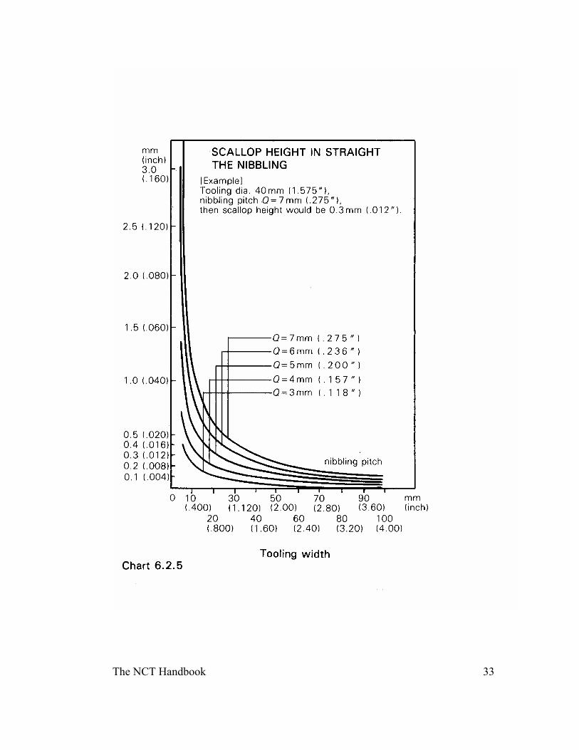
Tooling Selection Standard in Nibbling Process: ........................................... 27 (3) Scallop Height of Product When Corner Notching: .................................. 30
Notching and Nibbling Process - Nibbling at a Sharp Angle: ............................ 34
The NCT Handbook 3
Nibbling and Slugs .............................................................................................. 35 Minimum Number of Hits and Tooling Selection .................................................. 38
Selection Standard for Square and Rectangular Tooling .................................... 38 Square Tooling Selection Standard: ................................................................ 38 Standard Rectangular Tooling Selection:........................................................ 39 Tooling Selection for Thick Material.............................................................. 41 Tooling Selection for Thin Material................................................................ 42
Punching Procedure and Material Support.............................................................. 43 External Blanking:........................................................................................... 43 Notching: ......................................................................................................... 43 Notching: ......................................................................................................... 44 Multi-Workpiece Process Used for Large Product Pieces: ............................. 44
Warpage .............................................................................................................. 45 Warpage and Punching Procedure: ................................................................. 45 Corrective Actions for Warpage: ................................................................... 45 To Equalize Warpage: ..................................................................................... 46 Part Edge Damage........................................................................................... 47 Damage Caused by Snagging.......................................................................... 47
Micro-Joint Method................................................................................................. 48 Micro-Joint Method................................................................................................. 49
Number and Size of Micro-Joints ................................................................... 49 Different Type and Varieties of Micro-Joints: ............................................... 50 The Micro-joint Method.................................................................................. 51
Part Removal Methods ........................................................................................ 51 Manual Removal of Scrap............................................................................... 52
Nesting Methods and Material Sheets..................................................................... 54 Cut-to-Size and Standard Sheet Sizes: ............................................................ 54
The Nesting Method:........................................................................................... 54 Multi-Workpiece Processing Method: ............................................................ 54 Nesting and Material Sheet Size: .................................................................... 55
Nesting and Blanking .......................................................................................... 56 Blanking Method:........................................................................................... 56 Various Types of Nesting:............................................................................... 56
Forming Process...................................................................................................... 57 Louvering and Lancing ................................................................................... 58 Programming with Forming Tools .................................................................. 59 Beading Process .............................................................................................. 60 Forming and Punching Process ....................................................................... 61
Work Chute Applications........................................................................................ 62 The Work Chute and the Triple Track System: .............................................. 63 Applications Of The Work Chute ................................................................... 64
Auto-Index Devices................................................................................................. 65
The NCT Handbook 4
Preface (Amada Sheet Metal Working Research Association)
The rolling mill, with development beginning in the 18th century, reached higher
standards during the middle of the 19th century with the manufacture of steel plate. Thus, the history of sheet metal fabricating machines covers nearly three centuries. Modern sheet metal fabricating machines, however, made their appearance only twenty to thirty years ago. Presently, sheet metal processing together with punch presses, plays an important roll in the industry and will continue to do so in the future.
Sheet metal fabricating is currently used for many products such as communication equipment, kitchen appliances and medical instruments. The precision we can now obtain assures us that metal fabricating machines will play an important role in space exploration and energy development, where the slightest error is unacceptable. This will undoubtedly lead to the next technical revolution.
In order to meet the needs of the sheet metal industry, Amada Co., Ltd. has made an ongoing effort to accumulate both experience and data. This has strengthened our position as a pioneer and worldwide leader in the machine tool industry.
To keep you informed of the results of our ongoing research and development, the Amada Sheet Metal Working Research Association has decided to publish a series of books documenting our technical innovations. It is our hope that these publications will contribute to the further development of the industry.
This series of publications will describe the machines, punches and dies and shearing, punching, bending and welding information, as well as production techniques and controls for effective application. We will include as many charts, drawings and photographs as possible in each book. The information will be comprehensive with practical applications illustrated throughout.
We hope that this series of publications will be used as a reference to improve your technical knowledge as well as production efficiency throughout the sheet metal industry, thereby ensuring the continued growth of the industry.
The NCT Handbook 5
Advantages of Purchasing an NCT The metal working industry has gone through a transformation from mass
production to the current small and medium sized lots for just in time deliveries. In line with this change, the demand for production systems offering various applications and highly functional capabilities has increased tremendously.
The NC Turret Punch Press (NCT) is attracting attention from many industries as one of the most efficient machines to meet the requirements of diversified and multiple production needs for the production of quality products. Some of the advantages of using the NCT system are as follows:
Advantages in Production: —Increase productivity —Reduces overall costs —Improvements in accuracy and precision —Expansion of production capability —Increased safety
Advantages in Material Management: —Reduction of lot numbers —Simplification in determining material requirements —Increased production
Advantages in Production and Design: —Introduction of design changes made easier —More economic design and purchasing functions —Improved efficiency —Reduces need for skilled machinists —More uniform and accurate final products —Ability to store information in memory —Simplifies estimating and production
Advantages in Manufacturing:
—Reduces time spent moving materials
The NCT Handbook 6
—Reduces leadtime —Reduces manufacturing time —Reduces the number of production steps —Improved finished product —Simplifies the inspection process —Less training time —Reduces testing time —Less time required for tooling planning and arrangement —Reduces number of partially fabricated products
NCT Manufacturing System
One of the major needs in sheet metal manufacturing is to produce smaller batch quantities in shorter periods of time at lower costs. To increase productivity, it is important to have a flexible production system. To accomplish this, we must maintain and improve speed and accuracy and streamline the manufacturing procedure. We are constantly working toward a perfect balance of machine and software; one phase is to incorporate safety features in each machine; the other is to plan for easier and faster output by incorporating the best designs, command methods and production verification methods, with a constant emphasis on manufacturing management control. With this NCT system, we are striving to achieve the optimum unification of the machine and support hardware for the best automation and cost and labor reduction by utilizing the maximum capabilities of the many machine functions.
Manufacturing Capability—Function (1)
Using the NCT system will enable you to reduce or eliminate preliminary planning
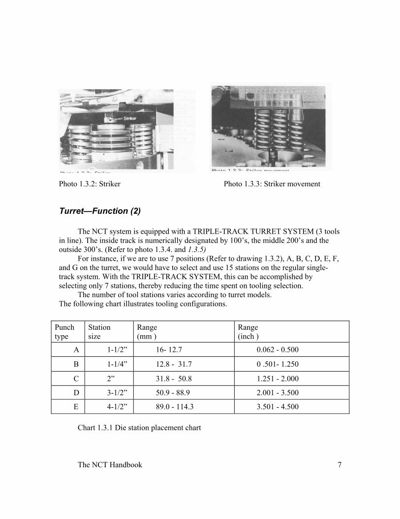
to meet the demands of contemporary production and the need for special tooling. An Early example of an NCT would be the COMA with a press capacity of 50 tons and 72 tool stations. This turret press has the ability to handle material up to 3/8”. Through the use of a computer command, the turret automatically selects the necessary tool. The tool selection can be made within 0.2 seconds when using the striker cylinder with 3 tracks. (Refer to photo 1.3.3 and drawing 1.3.1). .
The NCT Handbook 7
Photo 1.3.2: Striker Photo 1.3.3: Striker movement
Turret—Function (2)
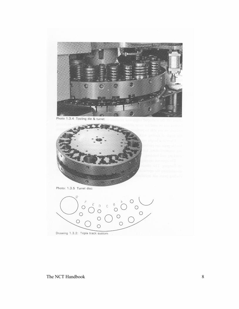
The NCT system is equipped with a TRIPLE-TRACK TURRET SYSTEM (3 tools
in line). The inside track is numerically designated by 100’s, the middle 200’s and the outside 300’s. (Refer to photo 1.3.4. and 1.3.5)
For instance, if we are to use 7 positions (Refer to drawing 1.3.2), A, B, C, D, E, F, and G on the turret, we would have to select and use 15 stations on the regular single-track system. With the TRIPLE-TRACK SYSTEM, this can be accomplished by selecting only 7 stations, thereby reducing the time spent on tooling selection.
The number of tool stations varies according to turret models. The following chart illustrates tooling configurations.
Chart 1.3.1 Die station placement chart
Punch type
Station size
Range (mm )
Range (inch )
A 1-1/2” 16- 12.7 0.062 - 0.500
B 1-1/4” 12.8 - 31.7 0 .501- 1.250
C 2” 31.8 - 50.8 1.251 - 2.000
D 3-1/2” 50.9 - 88.9 2.001 - 3.500
E 4-1/2” 89.0 - 114.3 3.501 - 4.500
The NCT Handbook 8
The NCT Handbook 9
Tool Selection—Function (3) As shown in chart 1.3.1, there are six station sizes. The tool holders are precision
manufactured, so by simply placing punches into the upper turret and dies into the lower turret, you are ready to begin fabrication, thereby reducing the need for special tooling. Selecting tooling stations with regard to auto index or fixed position will reduce the need for special tooling. Furthermore, it makes programming easier and reduces the chance of error. This naturally contributes to the standardization of product design. In addition, the AMADA NCT system is designed with fully contained self-stripping tooling. This prevents material distortion, extends tool life and maintains accuracy, resulting in precision fabricating.
Fabricating Shapes—Function (4)
Contour fabricating using the nibbling process is widely used, and with the use of
the factory-equipped milling attachment (Japan only), you can shave off the scalloped edges and produce neatly finished edges. Standard tooling can be used for most nibbling operations. By using the auto-indexing system, we are able to perform punching and outside blanking by changing the angle of tooling with computer commands.
There is a height restriction when forming (10mm (.250”) maximum), but the press can perform a variety of special forming processes such as Hanging, countersinking, louvering, lancing, knockouts, marking, coining, centermarking and beading.
The optional tapping attachment enables us to add a tapping process after Hanging. This eliminates the need for secondary handling, thus further streamlining the operation. Currently, advances are being made toward including press nut installation, eliminating the need for welded nuts.
Fundamental Guidelines for NCT Fabricating
Tooling:
(1) Always insert tooling firmly in place. (2) Always check punch and die sizes for correct match. (3) Eliminate turret movement by utilizing the TRIPLE TRACK SYSTEM. (4) Minimize loading and unloading of tooling by utilizing turret capacity. (5) Lubricate all tooling before use. (6) Sharpen tooling as needed. (7) Make sure the strippers make full contact with the material, especially when working with aluminum.
The NCT Handbook 10
Clearance:
(1) Always use proper clearances.
Punching procedures:
(1) Begin with small holes with larger ones last. (2) Begin punching in the area closest to the turret. (3) Make sure all individual parts are held firmly in place when punching multiples.
Clamps:
(1) Avoid punching near clamps. (2) Use the widest clamp spacing possible when selecting clamping positions. (3) Make sure clamping is accurate and that the material is correctly placed. (4) Make sure that the override switch is “ON” when processing a first sheet, to avoid punching the clamp.
Programming: (1) Avoid inputting any information which will cause the machine to stop during fabrication. (2) Program to best utilize machine movement. (3) Consider scrap shapes and sizes when programming. (4) Program to avoid punching where there is no material. Others: (1) Never attempt to fabricate anything beyond maximum press capacity. (2) Verify the dimension and size of the finished product on the first sheet. (3) Make a duplicate copy of the computer tape; one for immediate use and the other for future use. (4) Make sure the design number, clamping positions, material dimen sions material thickness and type of metal are recorded on the tape. (5) Enter data in a way which anyone can understand.
The NCT Handbook 11
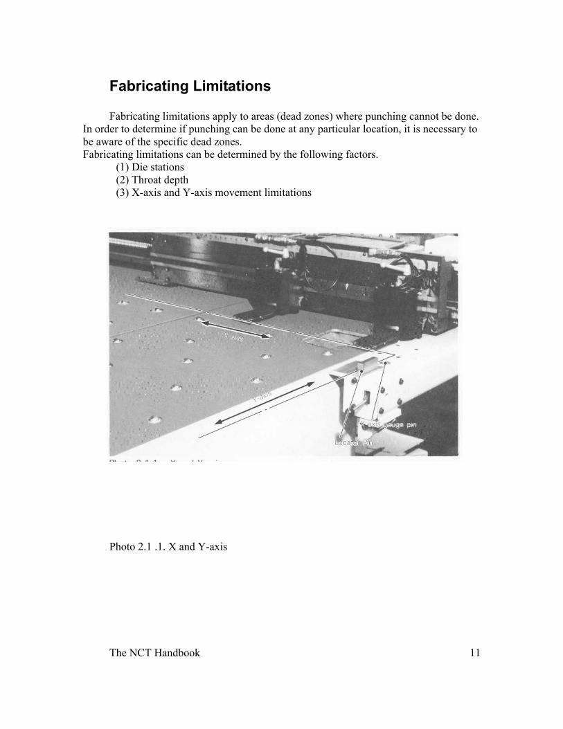
Fabricating Limitations Fabricating limitations apply to areas (dead zones) where punching cannot be done.
In order to determine if punching can be done at any particular location, it is necessary to be aware of the specific dead zones. Fabricating limitations can be determined by the following factors. (1) Die stations (2) Throat depth (3) X-axis and Y-axis movement limitations
Photo 2.1 .1. X and Y-axis
The NCT Handbook 12
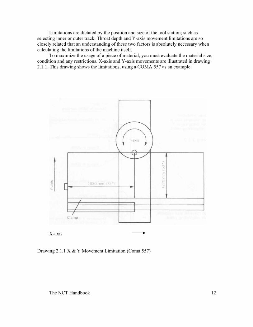
Limitations are dictated by the position and size of the tool station; such as selecting inner or outer track. Throat depth and Y-axis movement limitations are so closely related that an understanding of these two factors is absolutely necessary when calculating the limitations of the machine itself.
To maximize the usage of a piece of material, you must evaluate the material size, condition and any restrictions. X-axis and Y-axis movements are illustrated in drawing 2.1.1. This drawing shows the limitations, using a COMA 557 as an example.
X-axis
Drawing 2.1.1 X & Y Movement Limitation (Coma 557)
The NCT Handbook 13
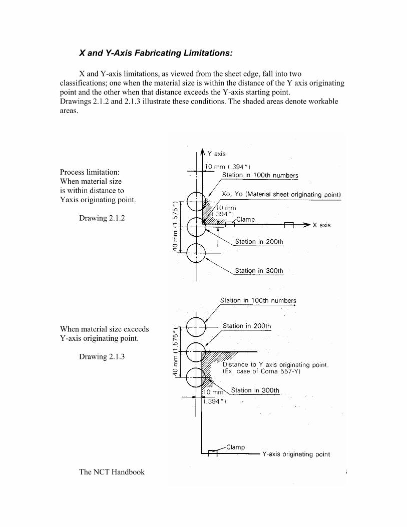
X and Y-Axis Fabricating Limitations: X and Y-axis limitations, as viewed from the sheet edge, fall into two
classifications; one when the material size is within the distance of the Y axis originating point and the other when that distance exceeds the Y-axis starting point. Drawings 2.1.2 and 2.1.3 illustrate these conditions. The shaded areas denote workable areas.
Process limitation: When material size is within distance to Yaxis originating point.
Drawing 2.1.2
When material size exceeds Y-axis originating point.
Drawing 2.1.3
The NCT Handbook 14
Tooling Installation Inspection of Tooling In an effort to protect your investment and minimize downtime, please follow the
guidelines in this handbook. Before the tools can be loaded into the machine, the protective grease must be removed from both the upper and lower turrets. A good cleaning solvent and bottle brushes will make this task a little easier.
Note: Do not remove the die holders from the lower turret. After the protective grease has been removed, apply a light coat of motor oil to both upper and lower turrets to protect against rust and corrosion.
All new tools should be inspected to assure correct size and/or shape. Also check for any damage caused during shipping. Notify the Tooling Order Desk within ten days of your receiving date, if there are any problems. After inspection, the tools should be
coated with a 20-30 weight detergent motor oil and stored in a clean safe environment (i.e. Rotary Cabinet). This will protect the tools from rust and corrosion.
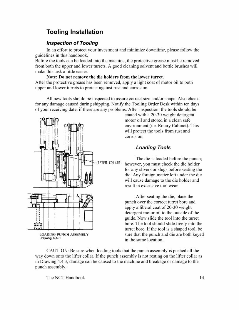
Loading Tools
The die is loaded before the punch; however, you must check the die holder for any slivers or slugs before seating the die. Any foreign matter left under the die will cause damage to the die holder and result in excessive tool wear.
After seating the die, place the punch over the correct turret bore and apply a liberal coat of 20-30 weight detergent motor oil to the outside of the guide. Now slide the tool into the turret bore. The tool should slide freely into the turret bore. If the tool is a shaped tool, be sure that the punch and die are both keyed in the same location.
CAUTION: Be sure when loading tools that the punch assembly is pushed all the way down onto the lifter collar. If the punch assembly is not resting on the lifter collar as in Drawing 4.4.3, damage can be caused to the machine and breakage or damage to the punch assembly.
The NCT Handbook 15
Periodic Maintenance: Daily:
1.Tighten the drawbolt on all 2”, 3-1/2” and 4-1/2” stations. 2.Tighten all stripper clip screws. 3.Lubricate all the tools that are in the turret with 20-30 weight detergent motor oil, between turret and guide.
Weekly:
1.Disassemble x and y rectangles (i.e. parting tools) and any other high usage tools. Clean, inspect and check for sharpness. If required, sharpen punch and die. Lubricate and assemble as explained earlier. 2.After approximately 80 hours of use, randomly select two guides and completely disassemble. If there is a build-up of grit in the driver area, all the guides should be removed and cleaned. Be certain to lubricate the driver and stripper springs.
Turret Alignment
The lower turret consists of individual die holders. This allows one station to be checked and aligned if misalignment is suspected. Misalignment may be noticed by excessive tool wear (i.e. one side wears more than the other). You will also notice that the break-out is not even on the back side of the punched part. Both cases indicate an alignment problem. The following pages will explain the correct procedure for alignment.
Turret
1) Centering the Die Holder The turret is located in position with shot pins. The shot pins locate the stations
under the striker position only. By adjusting the position of the die holder, alignment can be achieved.
1) Checking Alignment of ½” and 1-1/4” stations
a) Rotate tool station that needs checking to the loading position. b) Remove tooling and place alignment jigs into the outer and inner stations. c) Place a piece of cardboard between the die holder and alignment jig so the jig does not fall into the die. d) Rotate the turret to the strike position and place shot pins to “in” position. e) Remove cardboard and lower alignment jigs into die holder. If they slide in with no trouble the alignment is good. f) Replace cardboard between alignment jig and die holder before rotating turret back to the loading position.
The NCT Handbook 16
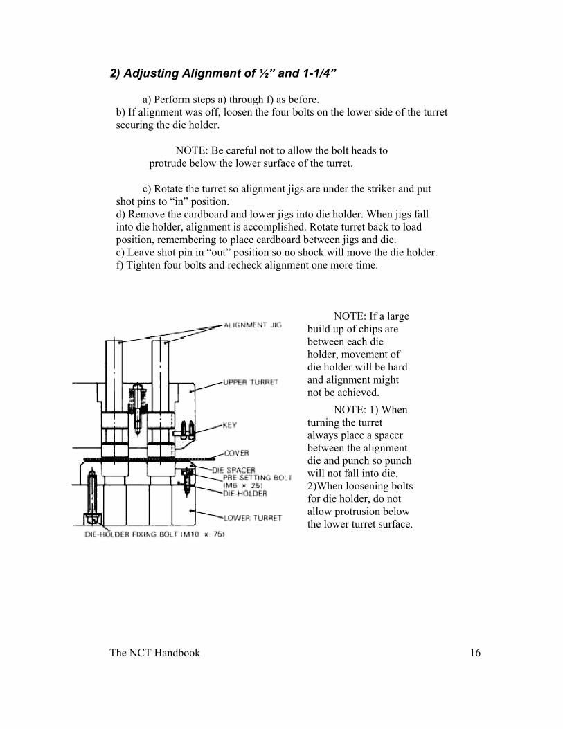
2) Adjusting Alignment of ½” and 1-1/4”
a) Perform steps a) through f) as before. b) If alignment was off, loosen the four bolts on the lower side of the turret securing the die holder.
NOTE: Be careful not to allow the bolt heads to protrude below the lower surface of the turret.
c) Rotate the turret so alignment jigs are under the striker and put shot pins to “in” position. d) Remove the cardboard and lower jigs into die holder. When jigs fall into die holder, alignment is accomplished. Rotate turret back to load position, remembering to place cardboard between jigs and die. c) Leave shot pin in “out” position so no shock will move the die holder. f) Tighten four bolts and recheck alignment one more time.
NOTE: If a large build up of chips are between each die holder, movement of die holder will be hard and alignment might not be achieved.
NOTE: 1) When turning the turret always place a spacer between the alignment die and punch so punch will not fall into die. 2)When loosening bolts for die holder, do not allow protrusion below the lower turret surface.
The NCT Handbook 17
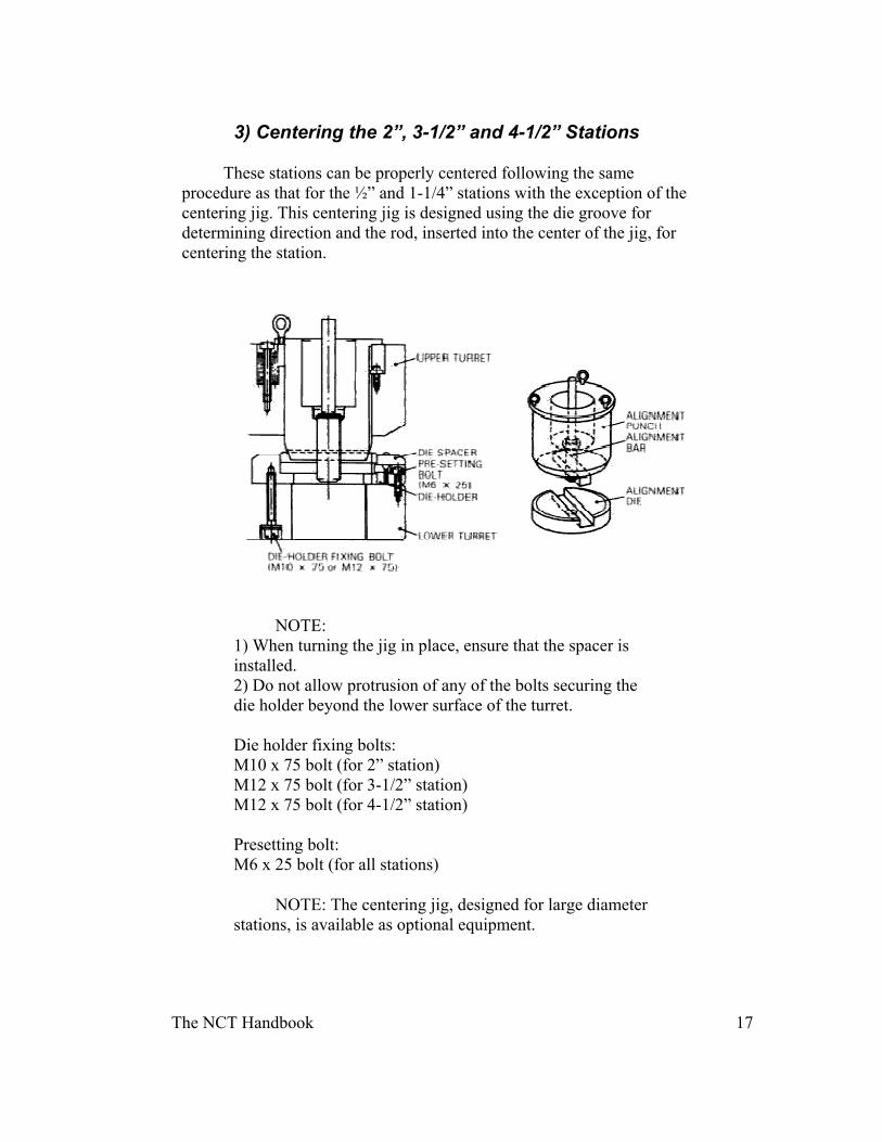
3) Centering the 2”, 3-1/2” and 4-1/2” Stations
These stations can be properly centered following the same procedure as that for the ½” and 1-1/4” stations with the exception of the centering jig. This centering jig is designed using the die groove for determining direction and the rod, inserted into the center of the jig, for centering the station.
NOTE:
1) When turning the jig in place, ensure that the spacer is installed. 2) Do not allow protrusion of any of the bolts securing the die holder beyond the lower surface of the turret. Die holder fixing bolts: M10 x 75 bolt (for 2” station) M12 x 75 bolt (for 3-1/2” station) M12 x 75 bolt (for 4-1/2” station) Presetting bolt: M6 x 25 bolt (for all stations)
NOTE: The centering jig, designed for large diameter stations, is available as optional equipment.
The NCT Handbook 18
Clearance
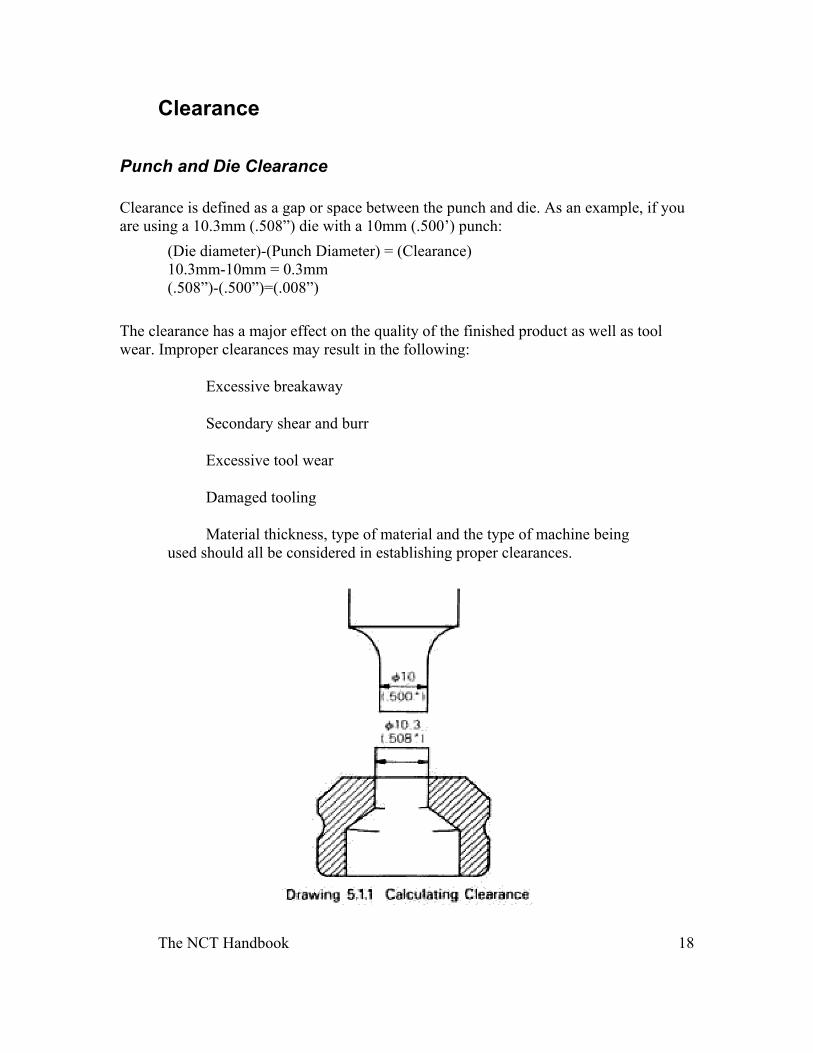
Punch and Die Clearance Clearance is defined as a gap or space between the punch and die. As an example, if you are using a 10.3mm (.508”) die with a 10mm (.500’) punch:
(Die diameter)-(Punch Diameter) = (Clearance) 10.3mm-10mm = 0.3mm (.508”)-(.500”)=(.008”)
The clearance has a major effect on the quality of the finished product as well as tool wear. Improper clearances may result in the following:
Excessive breakaway
Secondary shear and burr
Excessive tool wear
Damaged tooling
Material thickness, type of material and the type of machine being used should all be considered in establishing proper clearances.
The NCT Handbook 19
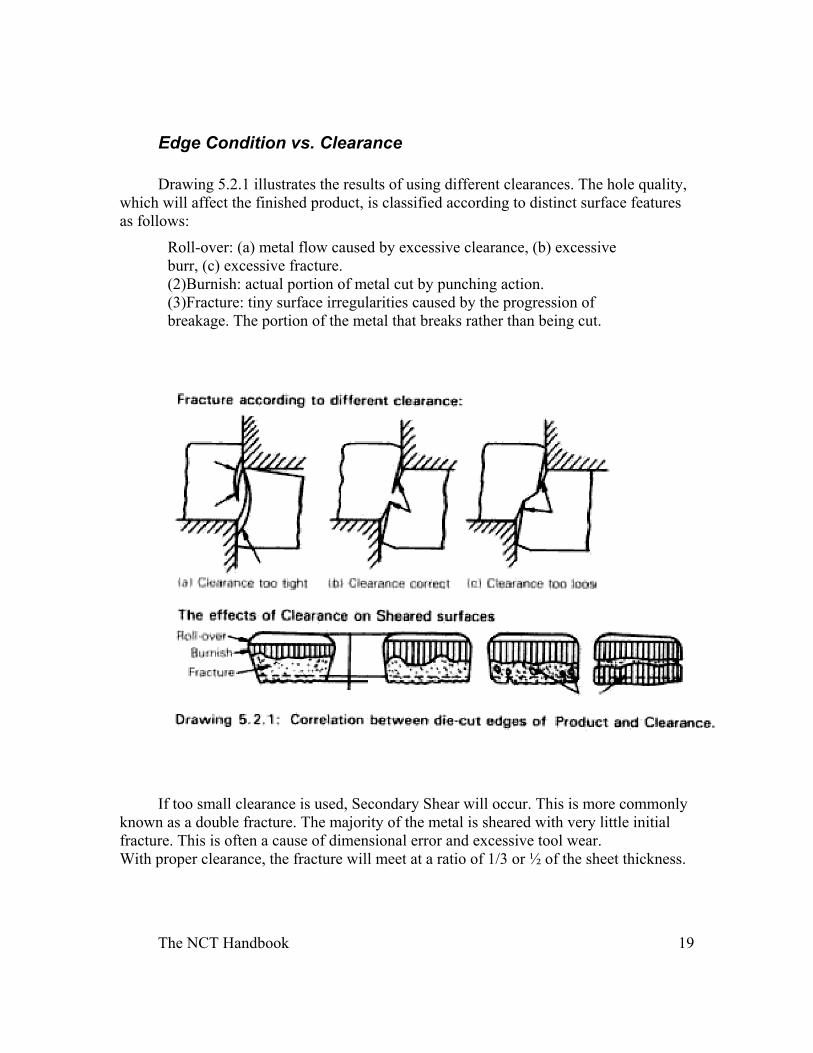
Edge Condition vs. Clearance Drawing 5.2.1 illustrates the results of using different clearances. The hole quality,
which will affect the finished product, is classified according to distinct surface features as follows:
Roll-over: (a) metal flow caused by excessive clearance, (b) excessive burr, (c) excessive fracture. (2)Burnish: actual portion of metal cut by punching action. (3)Fracture: tiny surface irregularities caused by the progression of breakage. The portion of the metal that breaks rather than being cut.
If too small clearance is used, Secondary Shear will occur. This is more commonly known as a double fracture. The majority of the metal is sheared with very little initial fracture. This is often a cause of dimensional error and excessive tool wear. With proper clearance, the fracture will meet at a ratio of 1/3 or ½ of the sheet thickness.
The NCT Handbook 20
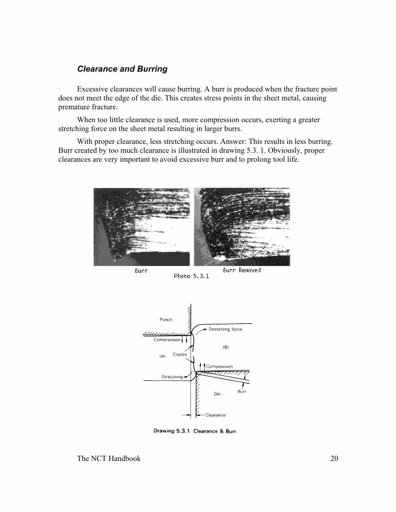
Clearance and Burring Excessive clearances will cause burring. A burr is produced when the fracture point
does not meet the edge of the die. This creates stress points in the sheet metal, causing premature fracture.
When too little clearance is used, more compression occurs, exerting a greater stretching force on the sheet metal resulting in larger burrs.
With proper clearance, less stretching occurs. Answer: This results in less burring. Burr created by too much clearance is illustrated in drawing 5.3. 1. Obviously, proper clearances are very important to avoid excessive burr and to prolong tool life.
The NCT Handbook 21
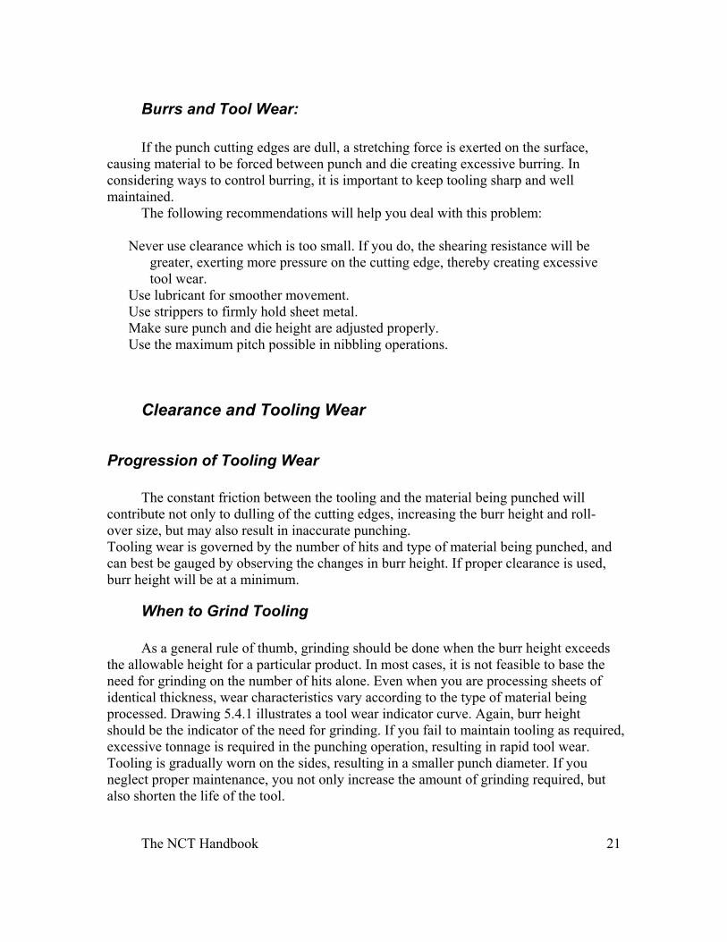
Burrs and Tool Wear:
If the punch cutting edges are dull, a stretching force is exerted on the surface, causing material to be forced between punch and die creating excessive burring. In considering ways to control burring, it is important to keep tooling sharp and well maintained.
The following recommendations will help you deal with this problem:
Never use clearance which is too small. If you do, the shearing resistance will be greater, exerting more pressure on the cutting edge, thereby creating excessive tool wear.
Use lubricant for smoother movement. Use strippers to firmly hold sheet metal. Make sure punch and die height are adjusted properly. Use the maximum pitch possible in nibbling operations.
Clearance and Tooling Wear
Progression of Tooling Wear
The constant friction between the tooling and the material being punched will
contribute not only to dulling of the cutting edges, increasing the burr height and roll-over size, but may also result in inaccurate punching. Tooling wear is governed by the number of hits and type of material being punched, and can best be gauged by observing the changes in burr height. If proper clearance is used, burr height will be at a minimum.
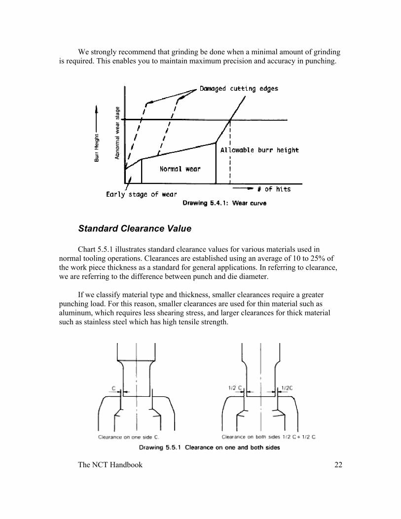
When to Grind Tooling As a general rule of thumb, grinding should be done when the burr height exceeds
the allowable height for a particular product. In most cases, it is not feasible to base the need for grinding on the number of hits alone. Even when you are processing sheets of identical thickness, wear characteristics vary according to the type of material being processed. Drawing 5.4.1 illustrates a tool wear indicator curve. Again, burr height should be the indicator of the need for grinding. If you fail to maintain tooling as required, excessive tonnage is required in the punching operation, resulting in rapid tool wear. Tooling is gradually worn on the sides, resulting in a smaller punch diameter. If you neglect proper maintenance, you not only increase the amount of grinding required, but also shorten the life of the tool.
The NCT Handbook 22
We strongly recommend that grinding be done when a minimal amount of grinding is required. This enables you to maintain maximum precision and accuracy in punching.
Standard Clearance Value Chart 5.5.1 illustrates standard clearance values for various materials used in
normal tooling operations. Clearances are established using an average of 10 to 25% of the work piece thickness as a standard for general applications. In referring to clearance, we are referring to the difference between punch and die diameter.
If we classify material type and thickness, smaller clearances require a greater punching load. For this reason, smaller clearances are used for thin material such as aluminum, which requires less shearing stress, and larger clearances for thick material such as stainless steel which has high tensile strength.
The NCT Handbook 23
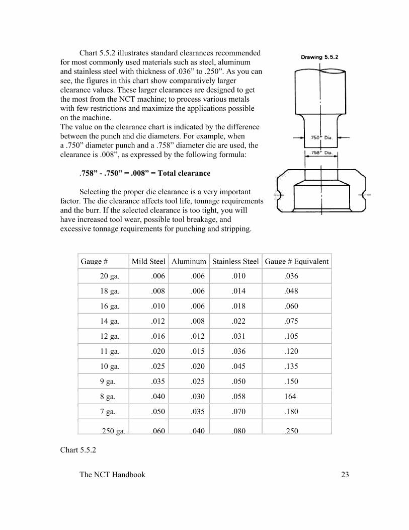
Chart 5.5.2 illustrates standard clearances recommended for most commonly used materials such as steel, aluminum and stainless steel with thickness of .036” to .250”. As you can see, the figures in this chart show comparatively larger clearance values. These larger clearances are designed to get the most from the NCT machine; to process various metals with few restrictions and maximize the applications possible on the machine. The value on the clearance chart is indicated by the difference between the punch and die diameters. For example, when a .750” diameter punch and a .758” diameter die are used, the clearance is .008”, as expressed by the following formula:
.758” - .750” = .008” = Total clearance
Selecting the proper die clearance is a very important factor. The die clearance affects tool life, tonnage requirements and the burr. If the selected clearance is too tight, you will have increased tool wear, possible tool breakage, and excessive tonnage requirements for punching and stripping.
Gauge # Mild Steel Aluminum Stainless Steel Gauge # Equivalent
20 ga. .006 .006 .010 .036
18 ga. .008 .006 .014 .048
16 ga. .010 .006 .018 .060
14 ga. .012 .008 .022 .075
12 ga. .016 .012 .031 .105
11 ga. .020 .015 .036 .120
10 ga. .025 .020 .045 .135
9 ga. .035 .025 .050 .150
8 ga. .040 .030 .058 164
7 ga. .050 .035 .070 .180
.250 ga. .060 .040 .080 .250 Chart 5.5.2
The NCT Handbook 24
Tooling Selection Before tooling selections are made, it is important to consider which tooling will
result in the best end product. Part quality and quantity should be considered when selecting standard, semi-standard or special tooling. You should always plan to use tooling with a punch size large enough to complete the punching operation with one hit. If more than one punch is required to complete a particular shape or hole, the nibbling process can be used. Close attention should also be paid as to the type of sheet metal to be processed.
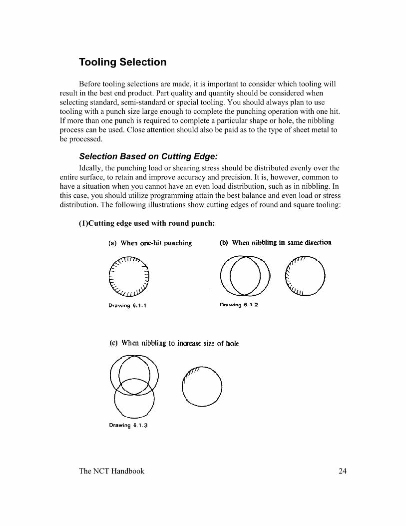
Selection Based on Cutting Edge: Ideally, the punching load or shearing stress should be distributed evenly over the
entire surface, to retain and improve accuracy and precision. It is, however, common to have a situation when you cannot have an even load distribution, such as in nibbling. In this case, you should utilize programming attain the best balance and even load or stress distribution. The following illustrations show cutting edges of round and square tooling:
(1)Cutting edge used with round punch:
The NCT Handbook 25
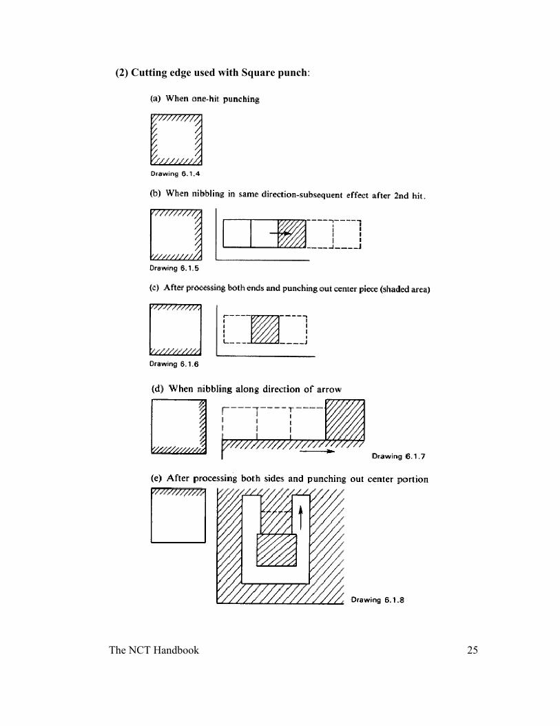
(2) Cutting edge used with Square punch:
The NCT Handbook 26
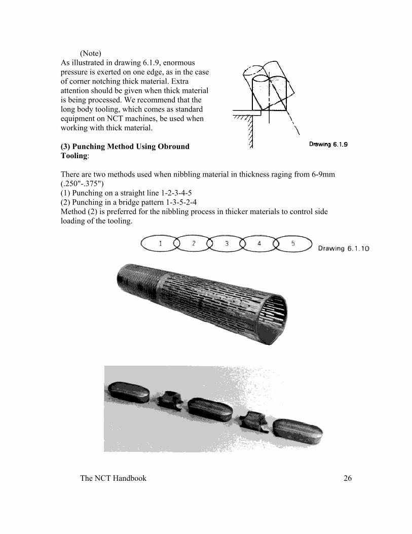
(Note) As illustrated in drawing 6.1.9, enormous pressure is exerted on one edge, as in the case of corner notching thick material. Extra attention should be given when thick material is being processed. We recommend that the long body tooling, which comes as standard equipment on NCT machines, be used when working with thick material.
(3) Punching Method Using Obround Tooling:
There are two methods used when nibbling material in thickness raging from 6-9mm (.250"-.375") (1) Punching on a straight line 1-2-3-4-5 (2) Punching in a bridge pattern 1-3-5-2-4 Method (2) is preferred for the nibbling process in thicker materials to control side loading of the tooling.
The NCT Handbook 27
Nibbling Process
Tooling Selection Standard in Nibbling Process:
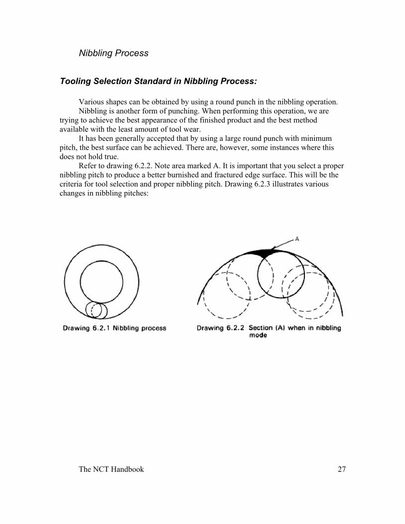
Various shapes can be obtained by using a round punch in the nibbling operation. Nibbling is another form of punching. When performing this operation, we are
trying to achieve the best appearance of the finished product and the best method available with the least amount of tool wear.
It has been generally accepted that by using a large round punch with minimum pitch, the best surface can be achieved. There are, however, some instances where this does not hold true.
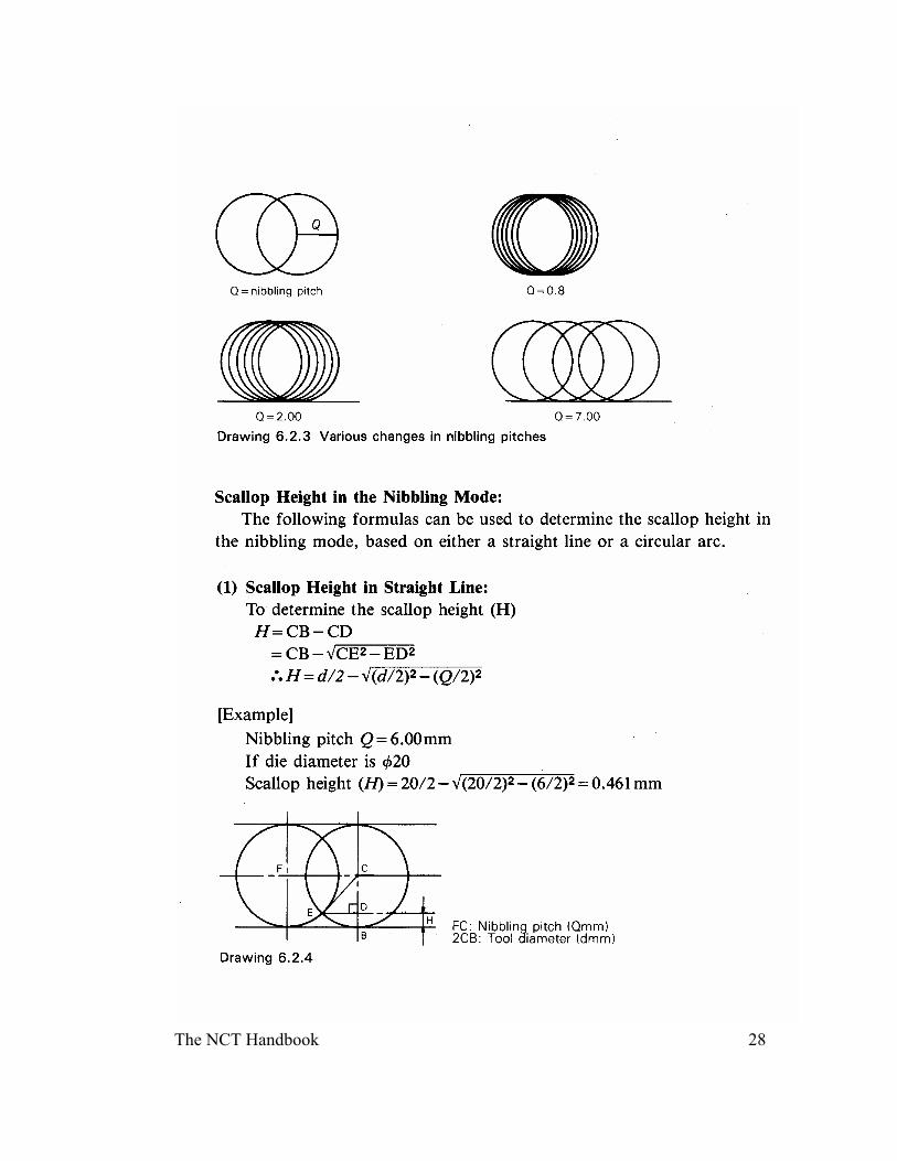
Refer to drawing 6.2.2. Note area marked A. It is important that you select a proper nibbling pitch to produce a better burnished and fractured edge surface. This will be the criteria for tool selection and proper nibbling pitch. Drawing 6.2.3 illustrates various changes in nibbling pitches:
The NCT Handbook 28
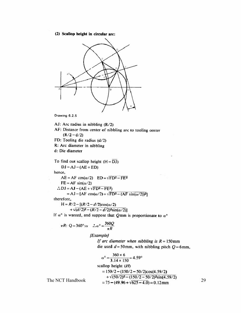
The NCT Handbook 29
The NCT Handbook 30
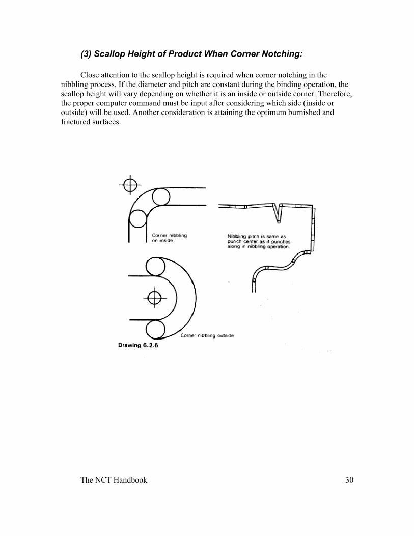
(3) Scallop Height of Product When Corner Notching: Close attention to the scallop height is required when corner notching in the
nibbling process. If the diameter and pitch are constant during the binding operation, the scallop height will vary depending on whether it is an inside or outside corner. Therefore, the proper computer command must be input after considering which side (inside or outside) will be used. Another consideration is attaining the optimum burnished and fractured surfaces.
The NCT Handbook 31
The NCT Handbook 32
The NCT Handbook 33
The NCT Handbook 34
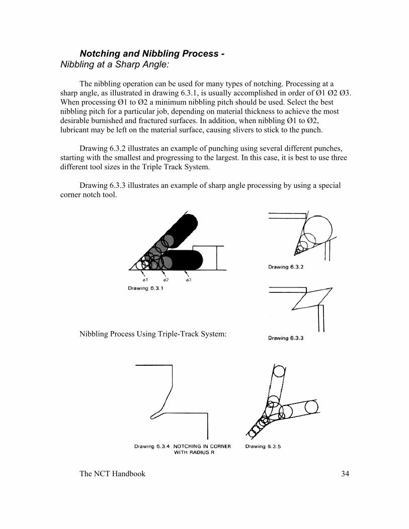
Notching and Nibbling Process - Nibbling at a Sharp Angle:
The nibbling operation can be used for many types of notching. Processing at a sharp angle, as illustrated in drawing 6.3.1, is usually accomplished in order of Ø1 Ø2 Ø3. When processing Ø1 to Ø2 a minimum nibbling pitch should be used. Select the best nibbling pitch for a particular job, depending on material thickness to achieve the most desirable burnished and fractured surfaces. In addition, when nibbling Ø1 to Ø2, lubricant may be left on the material surface, causing slivers to stick to the punch.
Drawing 6.3.2 illustrates an example of punching using several different punches, starting with the smallest and progressing to the largest. In this case, it is best to use three different tool sizes in the Triple Track System.
Drawing 6.3.3 illustrates an example of sharp angle processing by using a special corner notch tool.
Nibbling Process Using Triple-Track System:
The NCT Handbook 35
With the exclusive Triple Track System, three tools can be put into action with just one turret selection, moving the strikers in the nibbling operation.
When corner notching is required, as shown in drawing 6.3.4, the most efficient method would be using three tools.
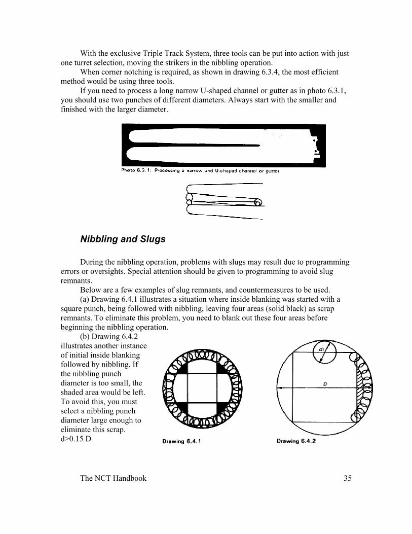
If you need to process a long narrow U-shaped channel or gutter as in photo 6.3.1, you should use two punches of different diameters. Always start with the smaller and finished with the larger diameter.
Nibbling and Slugs
During the nibbling operation, problems with slugs may result due to programming errors or oversights. Special attention should be given to programming to avoid slug remnants.
Below are a few examples of slug remnants, and countermeasures to be used. (a) Drawing 6.4.1 illustrates a situation where inside blanking was started with a
square punch, being followed with nibbling, leaving four areas (solid black) as scrap remnants. To eliminate this problem, you need to blank out these four areas before beginning the nibbling operation.
(b) Drawing 6.4.2 illustrates another instance of initial inside blanking followed by nibbling. If the nibbling punch diameter is too small, the shaded area would be left. To avoid this, you must select a nibbling punch diameter large enough to eliminate this scrap. d>0.15 D
The NCT Handbook 36
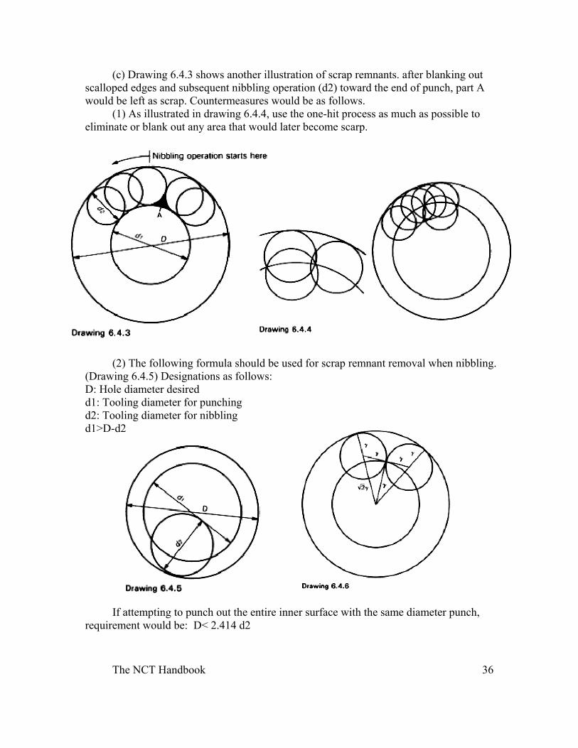
(c) Drawing 6.4.3 shows another illustration of scrap remnants. after blanking out scalloped edges and subsequent nibbling operation (d2) toward the end of punch, part A would be left as scrap. Countermeasures would be as follows.
(1) As illustrated in drawing 6.4.4, use the one-hit process as much as possible to eliminate or blank out any area that would later become scarp.
(2) The following formula should be used for scrap remnant removal when nibbling. (Drawing 6.4.5) Designations as follows: D: Hole diameter desired d1: Tooling diameter for punching d2: Tooling diameter for nibbling d1>D-d2
If attempting to punch out the entire inner surface with the same diameter punch, requirement would be: D< 2.414 d2
The NCT Handbook 37
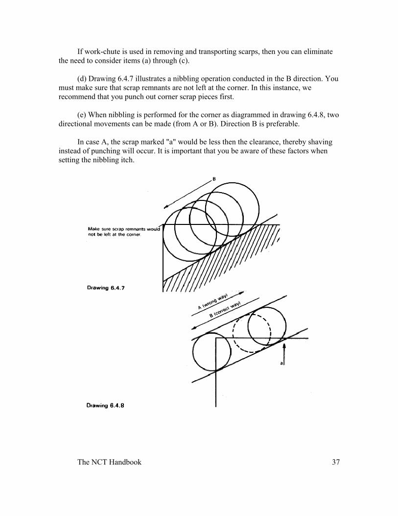
If work-chute is used in removing and transporting scarps, then you can eliminate the need to consider items (a) through (c).
(d) Drawing 6.4.7 illustrates a nibbling operation conducted in the B direction. You must make sure that scrap remnants are not left at the corner. In this instance, we recommend that you punch out corner scrap pieces first.
(e) When nibbling is performed for the corner as diagrammed in drawing 6.4.8, two directional movements can be made (from A or B). Direction B is preferable.
In case A, the scrap marked "a" would be less then the clearance, thereby shaving instead of punching will occur. It is important that you be aware of these factors when setting the nibbling itch.
The NCT Handbook 38
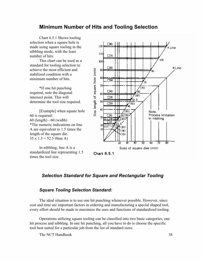
Minimum Number of Hits and Tooling Selection Chart 6.5.1 Shows tooling
selection when a square hole is made using square tooling in the nibbling mode, with the least number of hits.
This chart can be used as a standard for tooling selection to achieve the most efficient and stabilized condition with a minimum number of hits.
*If one hit punching required, note the diagonal intersect point. This will determine the tool size required.
[Example] when square hole 60 is required: 60 (length) - 60 (width) *The numeric indications on line A are equivalent to 1.5 times the length of the square die. 35 x 1.5 = 52.5 9line A)
In nibbling, line A is a standardized line representing 1.5 times the tool size.
Selection Standard for Square and Rectangular Tooling
Square Tooling Selection Standard: The ideal situation is to use one hit punching whenever possible. However, since
cost and time are important factors in ordering and manufacturing a special shaped tool, every effort should be made to maximize the uses and functions of standardized tooling.
Operations utilizing square tooling can be classified into two basic categories; one hit process and nibbling. In one hit punching, all you have to do is choose the specific tool best suited for a particular job from the list of standard sizes.
The NCT Handbook 39
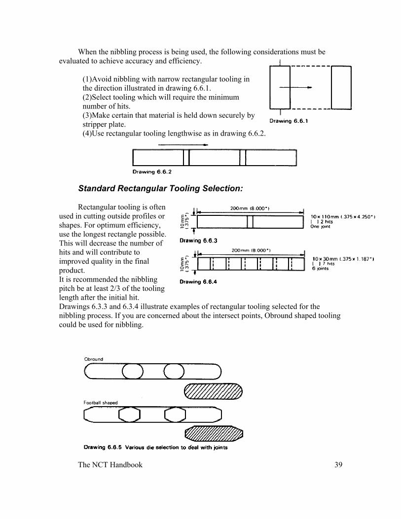
When the nibbling process is being used, the following considerations must be evaluated to achieve accuracy and efficiency.
(1)Avoid nibbling with narrow rectangular tooling in the direction illustrated in drawing 6.6.1. (2)Select tooling which will require the minimum number of hits. (3)Make certain that material is held down securely by stripper plate. (4)Use rectangular tooling lengthwise as in drawing 6.6.2.
Standard Rectangular Tooling Selection:
Rectangular tooling is often used in cutting outside profiles or shapes. For optimum efficiency, use the longest rectangle possible. This will decrease the number of hits and will contribute to improved quality in the final product. It is recommended the nibbling pitch be at least 2/3 of the tooling length after the initial hit. Drawings 6.3.3 and 6.3.4 illustrate examples of rectangular tooling selected for the nibbling process. If you are concerned about the intersect points, Obround shaped tooling could be used for nibbling.
The NCT Handbook 40
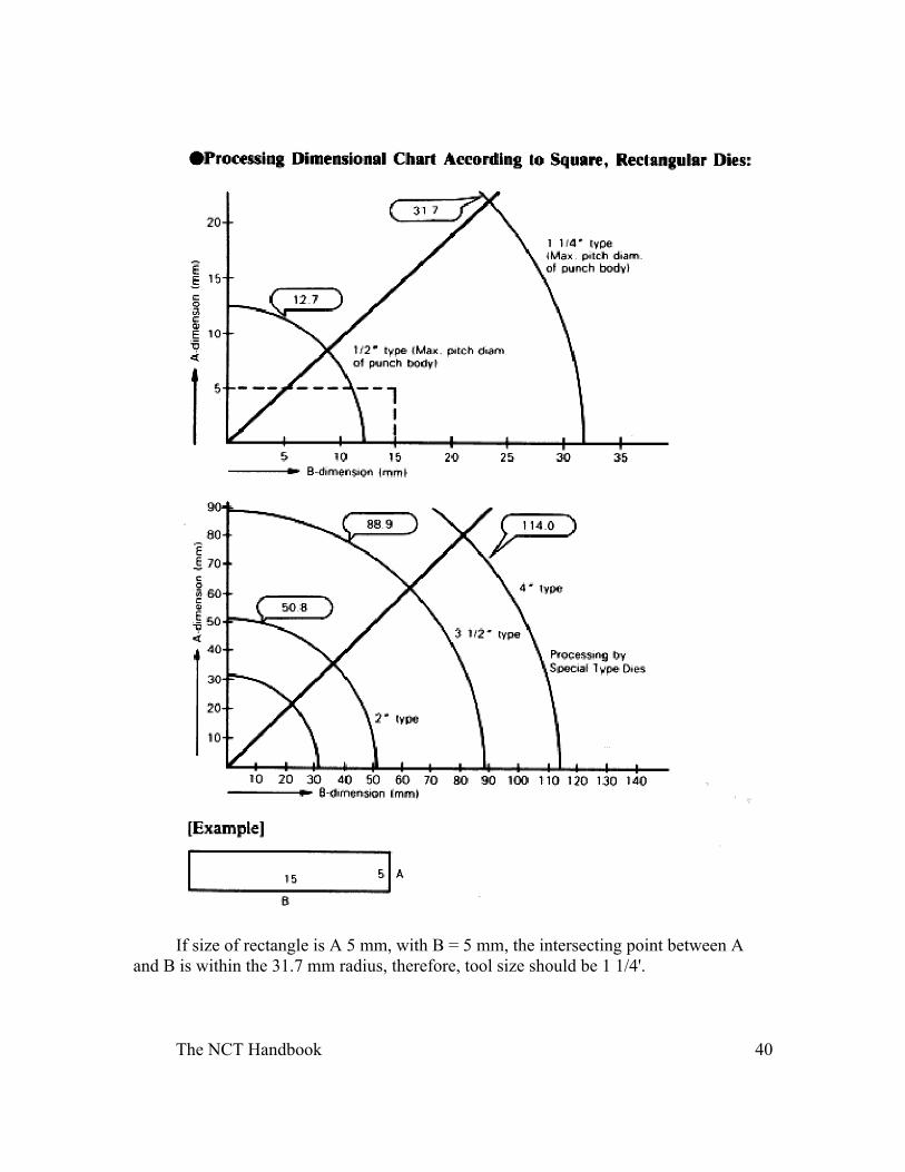
If size of rectangle is A 5 mm, with B = 5 mm, the intersecting point between A and B is within the 31.7 mm radius, therefore, tool size should be 1 1/4'.
The NCT Handbook 41
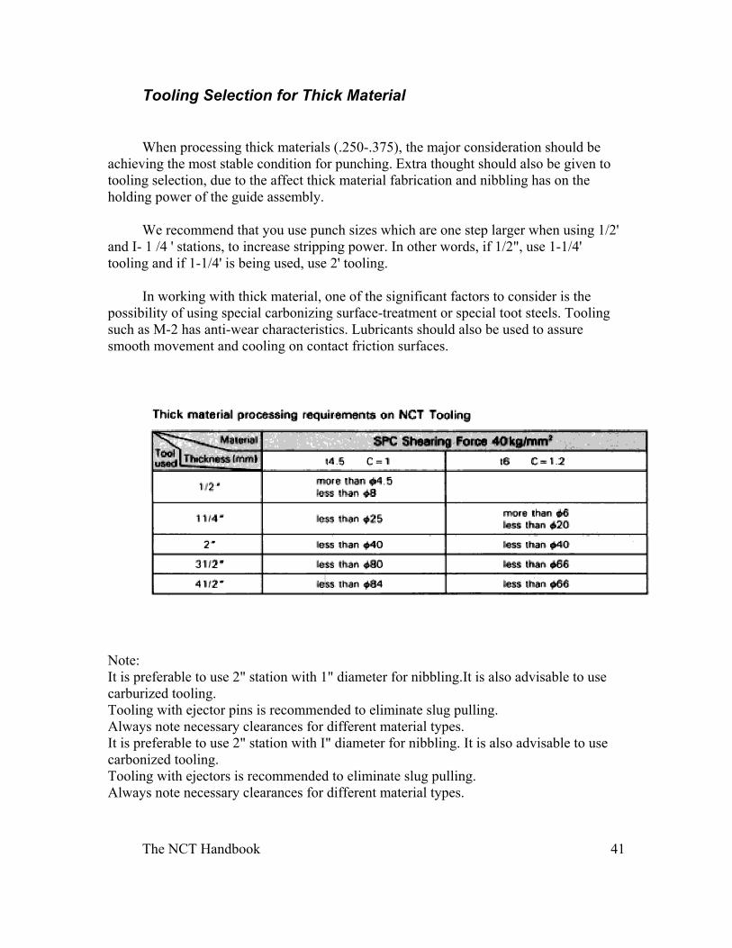
Tooling Selection for Thick Material
When processing thick materials (.250-.375), the major consideration should be achieving the most stable condition for punching. Extra thought should also be given to tooling selection, due to the affect thick material fabrication and nibbling has on the holding power of the guide assembly.
We recommend that you use punch sizes which are one step larger when using 1/2' and I- 1 /4 ' stations, to increase stripping power. In other words, if 1/2", use 1-1/4' tooling and if 1-1/4' is being used, use 2' tooling.
In working with thick material, one of the significant factors to consider is the possibility of using special carbonizing surface-treatment or special toot steels. Tooling such as M-2 has anti-wear characteristics. Lubricants should also be used to assure smooth movement and cooling on contact friction surfaces.
Note: It is preferable to use 2" station with 1" diameter for nibbling.It is also advisable to use carburized tooling. Tooling with ejector pins is recommended to eliminate slug pulling. Always note necessary clearances for different material types. It is preferable to use 2" station with I" diameter for nibbling. It is also advisable to use carbonized tooling. Tooling with ejectors is recommended to eliminate slug pulling. Always note necessary clearances for different material types.
The NCT Handbook 42
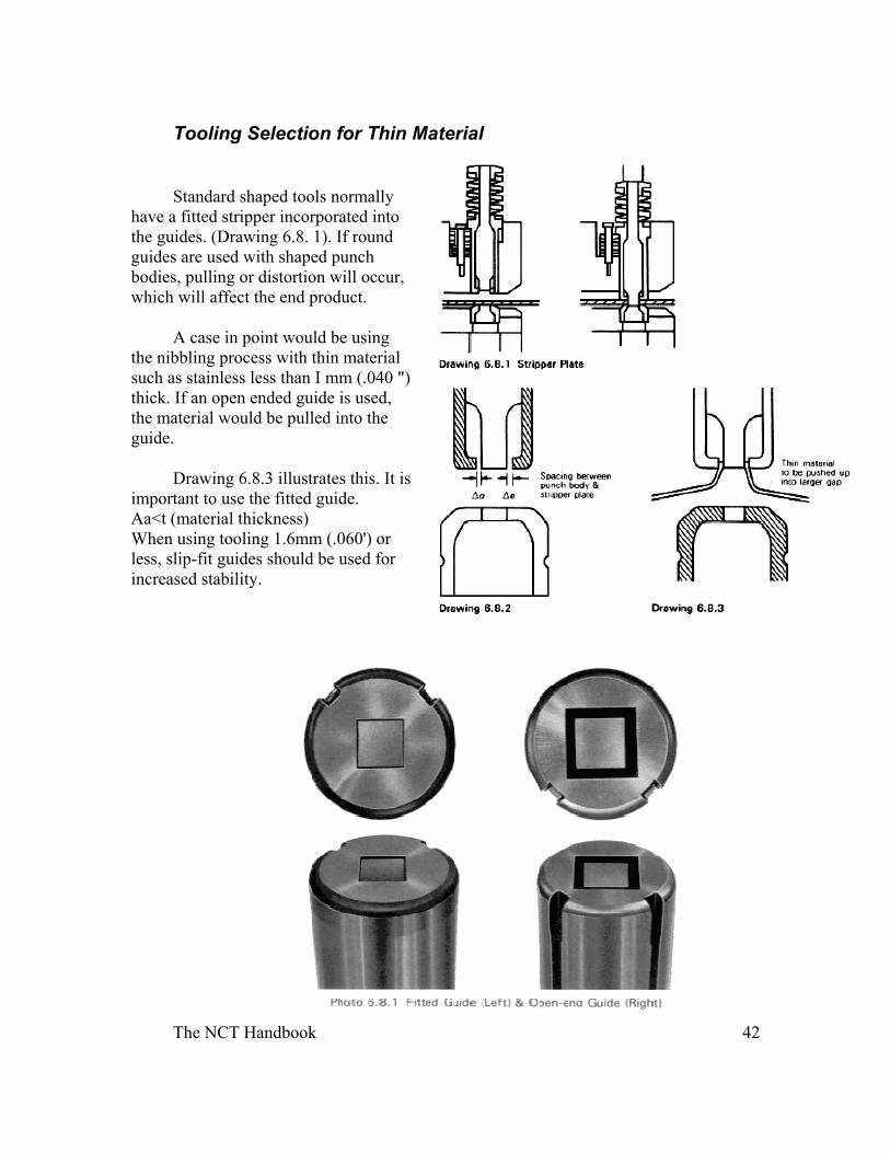
Tooling Selection for Thin Material
Standard shaped tools normally have a fitted stripper incorporated into the guides. (Drawing 6.8. 1). If round guides are used with shaped punch bodies, pulling or distortion will occur, which will affect the end product.
A case in point would be using the nibbling process with thin material such as stainless less than I mm (.040 ") thick. If an open ended guide is used, the material would be pulled into the guide.
Drawing 6.8.3 illustrates this. It is important to use the fitted guide. Aa<t (material thickness) When using tooling 1.6mm (.060') or less, slip-fit guides should be used for increased stability.
The NCT Handbook 43
Punching Procedure and Material Support
External Blanking:
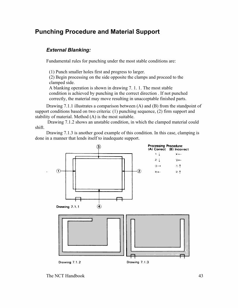
Fundamental rules for punching under the most stable conditions are:
(1) Punch smaller holes first and progress to larger. (2) Begin processing on the side opposite the clamps and proceed to the clamped side. A blanking operation is shown in drawing 7. 1. 1. The most stable condition is achieved by punching in the correct direction . If not punched correctly, the material may move resulting in unacceptable finished parts.
Drawing 7.1.1 illustrates a comparison between (A) and (B) from the standpoint of support conditions based on two criteria: (1) punching sequence, (2) firm support and stability of material. Method (A) is the most suitable.
Drawing 7.1.2 shows an unstable condition, in which the clamped material could shift.
Drawing 7.1.3 is another good example of this condition. In this case, clamping is done in a manner that lends itself to inadequate support.
.
The NCT Handbook 44
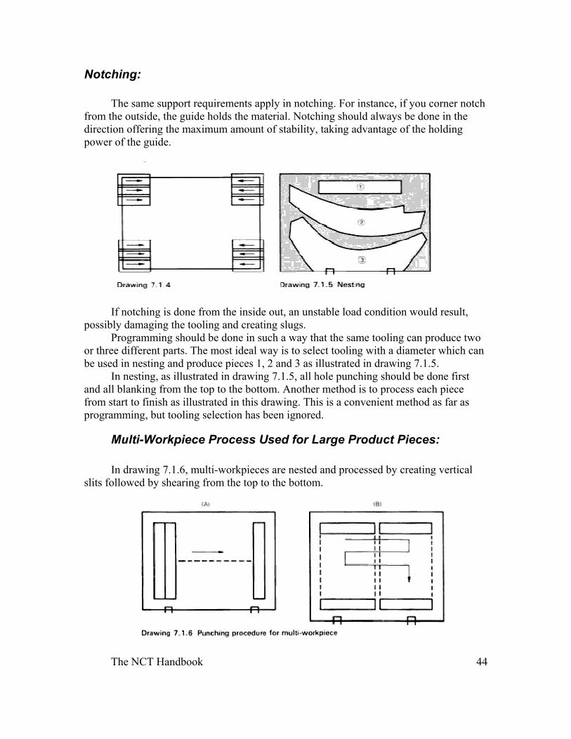
Notching: The same support requirements apply in notching. For instance, if you corner notch
from the outside, the guide holds the material. Notching should always be done in the direction offering the maximum amount of stability, taking advantage of the holding power of the guide.
If notching is done from the inside out, an unstable load condition would result, possibly damaging the tooling and creating slugs.
Programming should be done in such a way that the same tooling can produce two or three different parts. The most ideal way is to select tooling with a diameter which can be used in nesting and produce pieces 1, 2 and 3 as illustrated in drawing 7.1.5.
In nesting, as illustrated in drawing 7.1.5, all hole punching should be done first and all blanking from the top to the bottom. Another method is to process each piece from start to finish as illustrated in this drawing. This is a convenient method as far as programming, but tooling selection has been ignored.
Multi-Workpiece Process Used for Large Product Pieces:
In drawing 7.1.6, multi-workpieces are nested and processed by creating vertical slits followed by shearing from the top to the bottom.
The NCT Handbook 45
When the micro-joint method is used for producing large parts, the joints may not be stable enough to hold the parts together. There is no problem if each part within the sheet is manually removed after completion.
When punching as illustrated in drawing 7.1.6, you should use a method which will result in the least vibration possible. Example (B) is the preferred method, as the clamping position reduces vibration.
Warpage
Warpage and Punching Procedure:
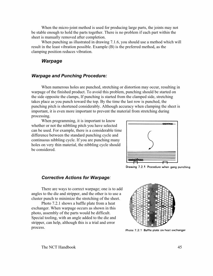
When numerous holes are punched, stretching or distortion may occur, resulting in warpage of the finished product. To avoid this problem, punching should be started on the side opposite the clamps, If punching is started from the clamped side, stretching takes place as you punch toward the top. By the time the last row is punched, the punching pitch is shortened considerably. Although accuracy when clamping the sheet is important, it is even more important to prevent the material from stretching during processing.
When programming, it is important to know whether or not the nibbling pitch you have selected can be used. For example, there is a considerable time difference between the standard punching cycle and continuous nibbling cycle. If you are punching many holes on very thin material, the nibbling cycle should be considered.
Corrective Actions for Warpage:
There are ways to correct warpage; one is to add angles to the die and stripper, and the other is to use a cluster punch to minimize the stretching of the sheet.
Photo 7.2.1 shows a baffle plate from a heat exchanger. When warpage occurs as shown in this photo, assembly of the parts would be difficult. Special tooling, with an angle added to the die and stripper, can help, although this is a trial and error process.
The NCT Handbook 46
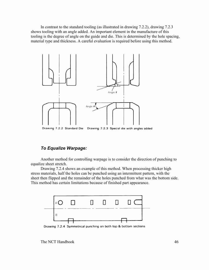
In contrast to the standard tooling (as illustrated in drawing 7.2.2), drawing 7.2.3 shows tooling with an angle added. An important element in the manufacture of this tooling is the degree of angle on the guide and die. This is determined by the hole spacing, material type and thickness. A careful evaluation is required before using this method.
To Equalize Warpage:
Another method for controlling warpage is to consider the direction of punching to equalize sheet stretch.
Drawing 7.2.4 shows an example of this method. When processing thicker high stress materials, half the holes can be punched using an intermittent pattern, with the sheet then flipped and the remainder of the holes punched from what was the bottom side. This method has certain limitations because of finished part appearance.
The NCT Handbook 47
Part Edge Damage
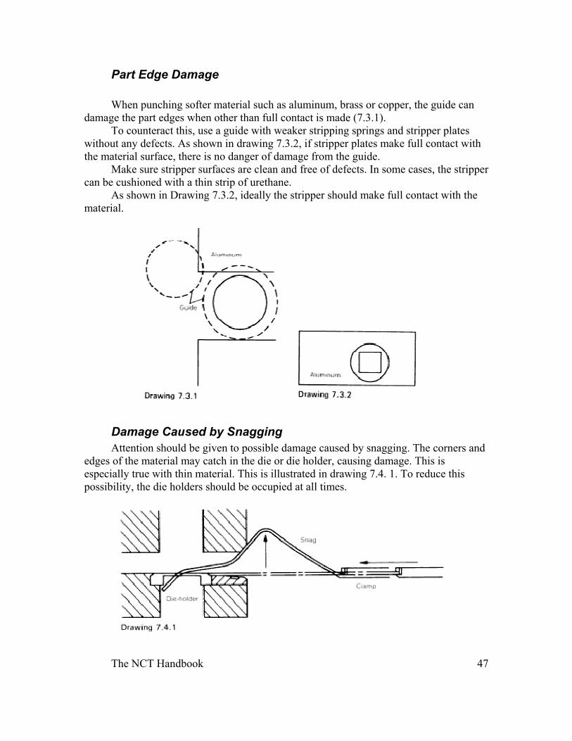
When punching softer material such as aluminum, brass or copper, the guide can damage the part edges when other than full contact is made (7.3.1).
To counteract this, use a guide with weaker stripping springs and stripper plates without any defects. As shown in drawing 7.3.2, if stripper plates make full contact with the material surface, there is no danger of damage from the guide.
Make sure stripper surfaces are clean and free of defects. In some cases, the stripper can be cushioned with a thin strip of urethane.
As shown in Drawing 7.3.2, ideally the stripper should make full contact with the material.
Damage Caused by Snagging Attention should be given to possible damage caused by snagging. The corners and
edges of the material may catch in the die or die holder, causing damage. This is especially true with thin material. This is illustrated in drawing 7.4. 1. To reduce this possibility, the die holders should be occupied at all times.
The NCT Handbook 48
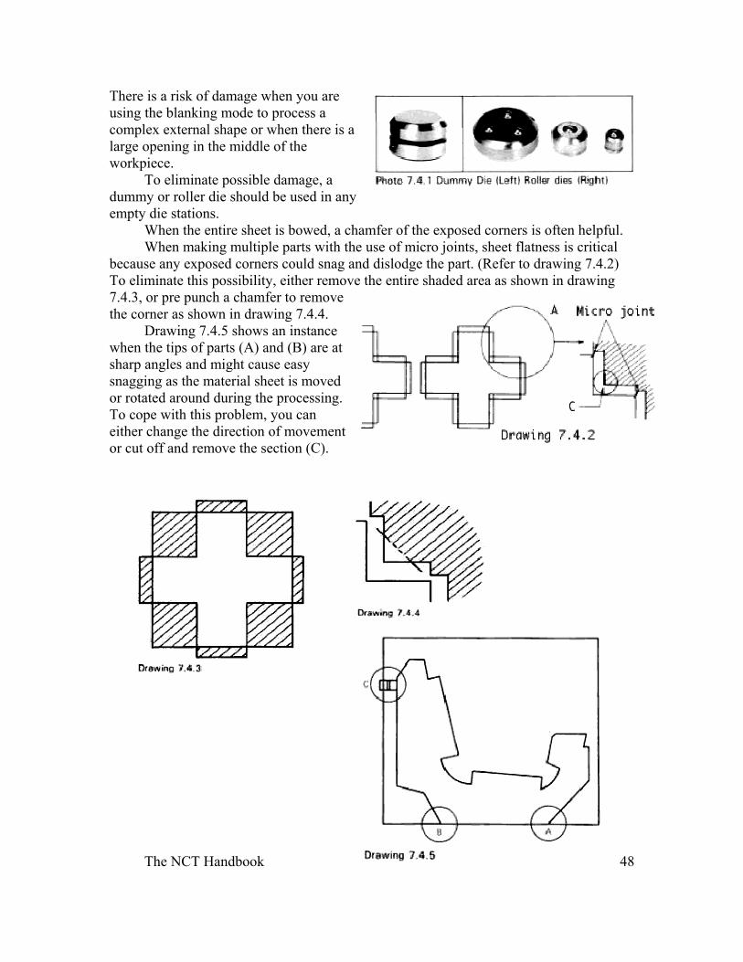
There is a risk of damage when you are using the blanking mode to process a complex external shape or when there is a large opening in the middle of the workpiece.
To eliminate possible damage, a dummy or roller die should be used in any empty die stations.
When the entire sheet is bowed, a chamfer of the exposed corners is often helpful. When making multiple parts with the use of micro joints, sheet flatness is critical
because any exposed corners could snag and dislodge the part. (Refer to drawing 7.4.2) To eliminate this possibility, either remove the entire shaded area as shown in drawing 7.4.3, or pre punch a chamfer to remove the corner as shown in drawing 7.4.4.
Drawing 7.4.5 shows an instance when the tips of parts (A) and (B) are at sharp angles and might cause easy snagging as the material sheet is moved or rotated around during the processing. To cope with this problem, you can either change the direction of movement or cut off and remove the section (C).
The NCT Handbook 49
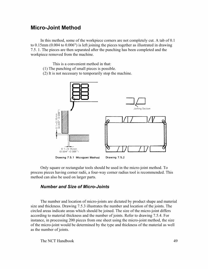
Micro-Joint Method
In this method, some of the workpiece corners are not completely cut. A tab of 0.1 to 0.15mm (0.004 to 0.006") is left joining the pieces together as illustrated in drawing 7.5. 1. The pieces are then separated after the punching has been completed and the workpiece removed from the machine.
This is a convenient method in that: (1) The punching of small pieces is possible. (2) It is not necessary to temporarily stop the machine.
Only square or rectangular tools should be used in the micro-joint method. To process pieces having corner radii, a four-way corner radius tool is recommended. This method can also be used on larger parts.
Number and Size of Micro-Joints
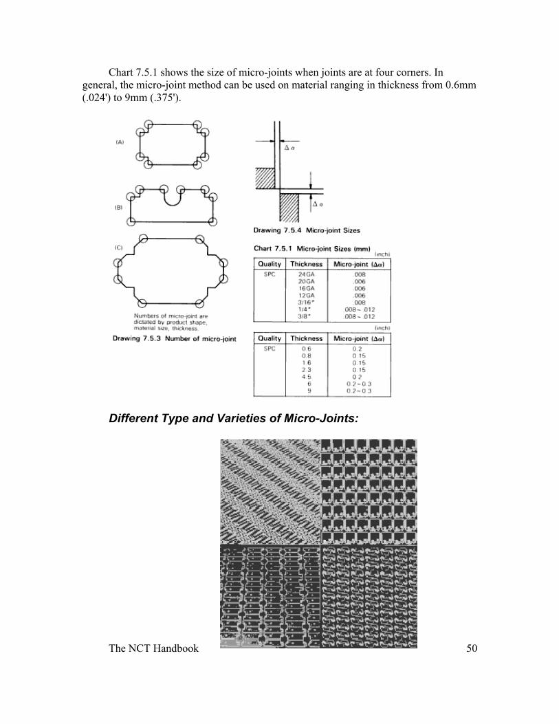
The number and location of micro-joints are dictated by product shape and material size and thickness. Drawing 7.5.3 illustrates the number and location of the joints. The circled areas indicate areas which should be joined. The size of the micro-joint differs according to material thickness and the number of joints. Refer to drawing 7.5.4. For instance, in processing 200 pieces from one sheet using the micro-joint method, the size of the micro-joint would be determined by the type and thickness of the material as well as the number of joints.
The NCT Handbook 50
Chart 7.5.1 shows the size of micro-joints when joints are at four corners. In general, the micro-joint method can be used on material ranging in thickness from 0.6mm (.024') to 9mm (.375').
Different Type and Varieties of Micro-Joints:
The NCT Handbook 51
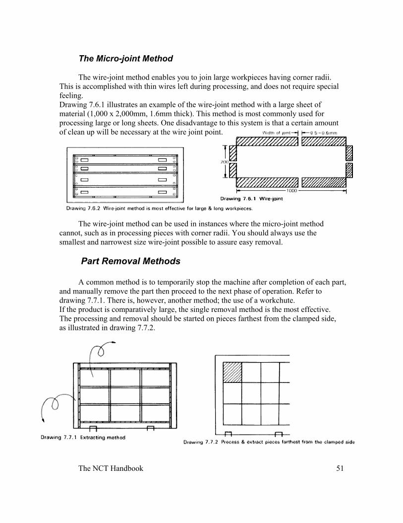
The Micro-joint Method
The wire-joint method enables you to join large workpieces having corner radii. This is accomplished with thin wires left during processing, and does not require special feeling. Drawing 7.6.1 illustrates an example of the wire-joint method with a large sheet of material (1,000 x 2,000mm, 1.6mm thick). This method is most commonly used for processing large or long sheets. One disadvantage to this system is that a certain amount of clean up will be necessary at the wire joint point.
The wire-joint method can be used in instances where the micro-joint method cannot, such as in processing pieces with corner radii. You should always use the smallest and narrowest size wire-joint possible to assure easy removal.
Part Removal Methods A common method is to temporarily stop the machine after completion of each part,
and manually remove the part then proceed to the next phase of operation. Refer to drawing 7.7.1. There is, however, another method; the use of a workchute. If the product is comparatively large, the single removal method is the most effective. The processing and removal should be started on pieces farthest from the clamped side, as illustrated in drawing 7.7.2.
The NCT Handbook 52
Manual Removal of Scrap
You can determine if manual removal of scrap should be used by evaluating the time spent in temporarily stopping the machine and removing scrap.
You should always aim for one continuous processing operation from start to finish without having to stop the machine. The following should be evaluated before deciding to use the manual removal method.
(1) Can micro-jointing be used? (2) Can a workchute be used? (3) Compare the number of blanking operations involved vs. the processing time. (4) Is there enough manpower available for manual removal of scrap with each stop of the machine?
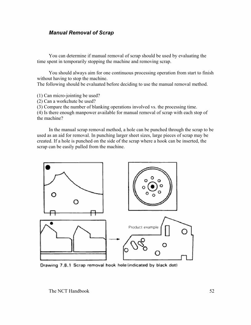
In the manual scrap removal method, a hole can be punched through the scrap to be used as an aid for removal. In punching larger sheet sizes, large pieces of scrap may be created. If a hole is punched on the side of the scrap where a hook can be inserted, the scrap can be easily pulled from the machine.
The NCT Handbook 53
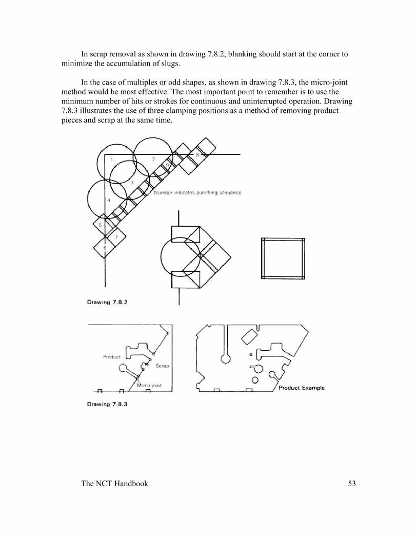
In scrap removal as shown in drawing 7.8.2, blanking should start at the corner to minimize the accumulation of slugs.
In the case of multiples or odd shapes, as shown in drawing 7.8.3, the micro-joint method would be most effective. The most important point to remember is to use the minimum number of hits or strokes for continuous and uninterrupted operation. Drawing 7.8.3 illustrates the use of three clamping positions as a method of removing product pieces and scrap at the same time.
The NCT Handbook 54
Nesting Methods and Material Sheets
Cut-to-Size and Standard Sheet Sizes: Before discussion nesting methods, it is important to understand the distinctive
features and characteristics of the material sheets. Material sheets can be classified in two types; cut-to-size and standard mill sizes.
Cut-to-size is defined as material which is cut to the dimensions of the finished product. Special care should be given in determining that metal grain (rolled direction) is in the correct direction.
Standard sheet size materials are standard industrial regulation sizes which are readily available, such as 3 ' x 8', 4' x 10' and 4' x 12'. These sheets are used in multi-workplace processing and when blanking is required,
The Nesting Method: The nesting method can be used when:
(1)you want to achieve maximum utilization from the material in processing for a specific product. (2)you want to determine mechanical limitations and requirements in nesting, the primary goal is to obtain the maximum yield from each sheet. Mechanical limitations such as dead zones and clamping restrictions are important considerations in nesting.
Three methods of nesting are used for multi-workpiece processing:
(1)Identical workpieces are nested and processed on regular-size sheets. (2)Many different types of workpieces are processed. (3)A single product is grouped together to minimize scrap.
Multi-Workpiece Processing Method:
As the name implies, multi-workpiece processing involves a number of pieces being punch concurrently from a single sheet of material. This process is controlled through the NCT software system. By using this method, you can process small workpieces in a shorter period of time thereby increasing productivity.
In multi-workpiece processing, cutting and punching can be conducted simultaneously, thus eliminating the shearing process. It also gives you the ability to improve product quality without accumulation of dimensional error. The benefits of increased accuracy will be realized in subsequent phases of processing such as bending
The NCT Handbook 55
and assembly. An additional advantage would be the ability to store flat parts which are easier to store than formed, thus aiding in just-in-time planning.
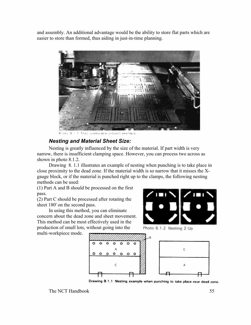
Nesting and Material Sheet Size: Nesting is greatly influenced by the size of the material. If part width is very
narrow, there is insufficient clamping space. However, you can process two across as shown in photo 8.1.2.
Drawing 8. 1.1 illustrates an example of nesting when punching is to take place in close proximity to the dead zone. If the material width is so narrow that it misses the X-gauge block, or if the material is punched right up to the clamps, the following nesting methods can be used: (1) Part A and B should be processed on the first pass. (2) Part C should be processed after rotating the sheet 180' on the second pass.
In using this method, you can eliminate concern about the dead zone and sheet movement. This method can be most effectively used in the production of small lots, without going into the multi-workpiece mode.
The NCT Handbook 56
Nesting and Blanking
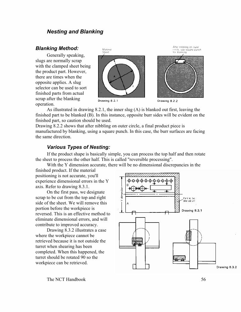
Blanking Method:
Generally speaking, slugs are normally scrap with the clamped sheet being the product part. However, there are times when the opposite applies. A slug selector can be used to sort finished parts from actual scrap after the blanking operation.
As illustrated in drawing 8.2.1, the inner slug (A) is blanked out first, leaving the finished part to be blanked (B). In this instance, opposite burr sides will be evident on the finished part, so caution should be used. Drawing 8.2.2 shows that after nibbling on outer circle, a final product piece is manufactured by blanking, using a square punch. In this case, the burr surfaces are facing the same direction.
Various Types of Nesting: If the product shape is basically simple, you can process the top half and then rotate
the sheet to process the other half. This is called "reversible processing". With the Y dimension accurate, there will be no dimensional discrepancies in the
finished product. If the material positioning is not accurate, you'll experience dimensional errors in the Y axis. Refer to drawing 8.3.1.
On the first pass, we designate scrap to be cut from the top and right side of the sheet. We will remove this portion before the workpiece is reversed. This is an effective method to eliminate dimensional errors, and will contribute to improved accuracy.
Drawing 8.3.2 illustrates a case where the workpiece cannot be retrieved because it is not outside the turret when shearing has been completed. When this happened, the turret should be rotated 90 so the workpiece can be retrieved.
The NCT Handbook 57
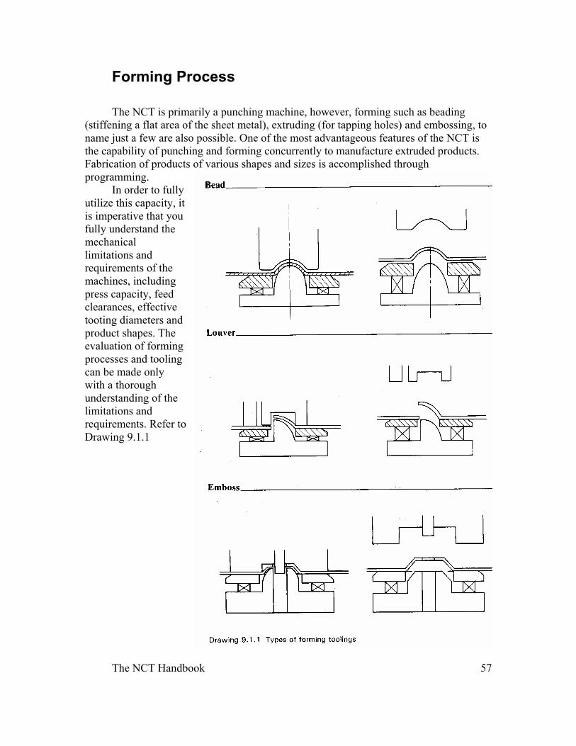
Forming Process
The NCT is primarily a punching machine, however, forming such as beading (stiffening a flat area of the sheet metal), extruding (for tapping holes) and embossing, to name just a few are also possible. One of the most advantageous features of the NCT is the capability of punching and forming concurrently to manufacture extruded products. Fabrication of products of various shapes and sizes is accomplished through programming.
In order to fully utilize this capacity, it is imperative that you fully understand the mechanical limitations and requirements of the machines, including press capacity, feed clearances, effective tooting diameters and product shapes. The evaluation of forming processes and tooling can be made only with a thorough understanding of the limitations and requirements. Refer to Drawing 9.1.1
The NCT Handbook 58
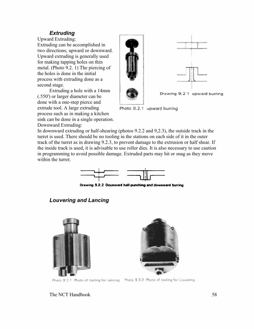
Extruding Upward Extruding: Extruding can be accomplished in two directions; upward or downward. Upward extruding is generally used for making tapping holes on thin metal. (Photo 9.2. 1) The piercing of the holes is done in the initial process with extruding done as a second stage.
Extruding a hole with a 14mm (.550') or larger diameter can be done with a one-step pierce and extrude tool. A large extruding process such as in making a kitchen sink can be done in a single operation. Downward Extruding: In downward extruding or half-shearing (photos 9.2.2 and 9,2.3), the outside track in the turret is used. There should be no tooling in the stations on each side of it in the outer track of the turret as in drawing 9.2.3, to prevent damage to the extrusion or half shear. If the inside track is used, it is advisable to use roller dies. It is also necessary to use caution in programming to avoid possible damage. Extruded parts may hit or snag as they move within the turret.
Louvering and Lancing
The NCT Handbook 59
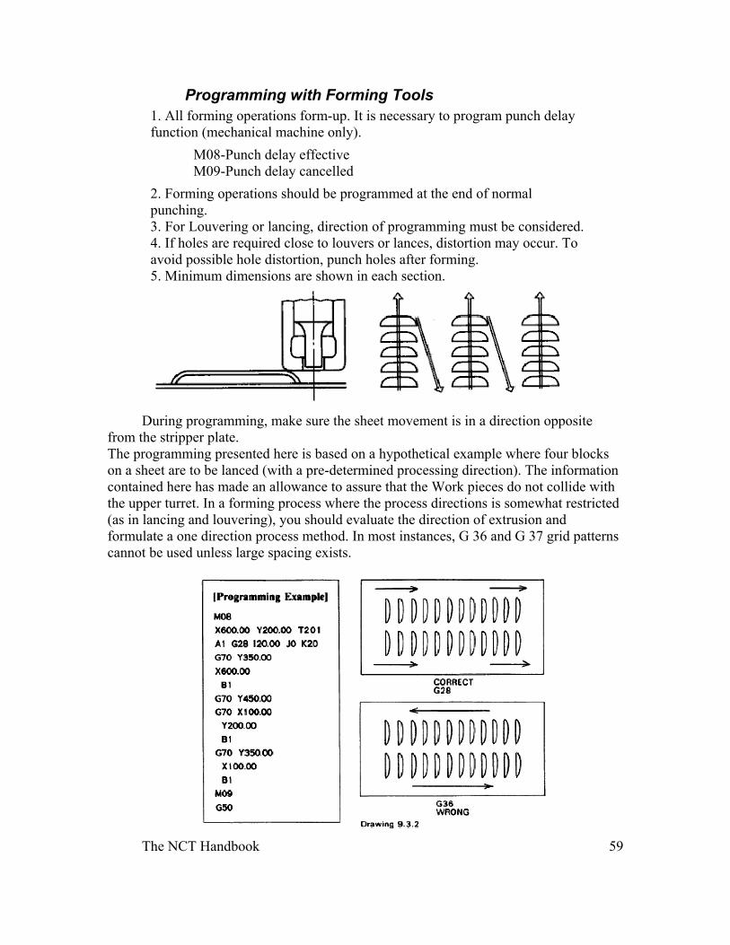
Programming with Forming Tools 1. All forming operations form-up. It is necessary to program punch delay function (mechanical machine only).
M08-Punch delay effective M09-Punch delay cancelled
2. Forming operations should be programmed at the end of normal punching. 3. For Louvering or lancing, direction of programming must be considered. 4. If holes are required close to louvers or lances, distortion may occur. To avoid possible hole distortion, punch holes after forming. 5. Minimum dimensions are shown in each section.
During programming, make sure the sheet movement is in a direction opposite
from the stripper plate. The programming presented here is based on a hypothetical example where four blocks on a sheet are to be lanced (with a pre-determined processing direction). The information contained here has made an allowance to assure that the Work pieces do not collide with the upper turret. In a forming process where the process directions is somewhat restricted (as in lancing and louvering), you should evaluate the direction of extrusion and formulate a one direction process method. In most instances, G 36 and G 37 grid patterns cannot be used unless large spacing exists.
The NCT Handbook 60
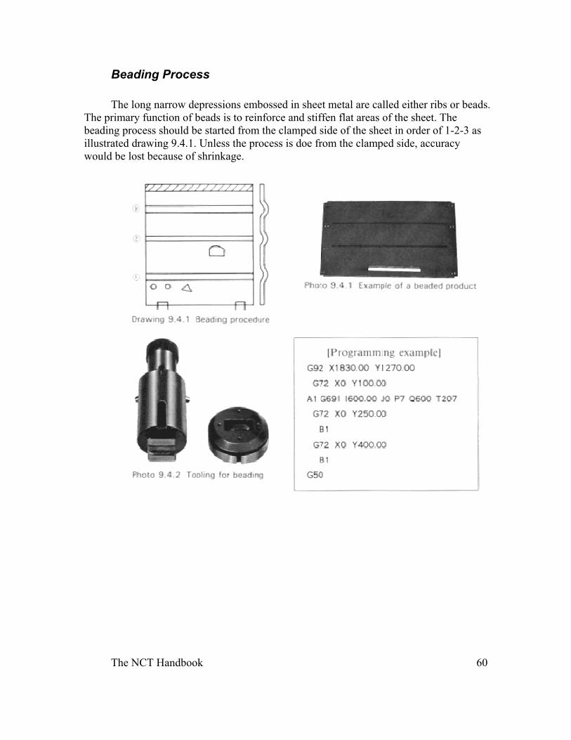
Beading Process
The long narrow depressions embossed in sheet metal are called either ribs or beads. The primary function of beads is to reinforce and stiffen flat areas of the sheet. The beading process should be started from the clamped side of the sheet in order of 1-2-3 as illustrated drawing 9.4.1. Unless the process is doe from the clamped side, accuracy would be lost because of shrinkage.
The NCT Handbook 61
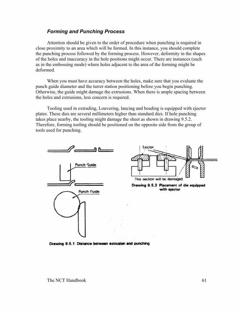
Forming and Punching Process
Attention should be given to the order of procedure when punching is required in close proximity to an area which will be formed. In this instance, you should complete the punching process followed by the forming process. However, deformity in the shapes of the holes and inaccuracy in the hole positions might occur. There are instances (such as in the embossing mode) where holes adjacent to the area of the forming might be deformed.
When you must have accuracy between the holes, make sure that you evaluate the punch guide diameter and the turret station positioning before you begin punching. Otherwise, the guide might damage the extrusions. When there is ample spacing between the holes and extrusions, less concern is required.
Tooling used in extruding, Louvering, lancing and beading is equipped with ejector plates. These dies are several millimeters higher than standard dies. If hole punching takes place nearby, the tooling might damage the sheet as shown in drawing 9.5.2. Therefore, forming tooling should be positioned on the opposite side from the group of tools used for punching.
The NCT Handbook 62
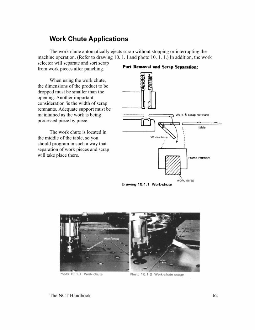
Work Chute Applications
The work chute automatically ejects scrap without stopping or interrupting the machine operation. (Refer to drawing 10. 1. I and photo 10. 1. 1.) In addition, the work selector will separate and sort scrap from work pieces after punching.
When using the work chute, the dimensions of the product to be dropped must be smaller than the opening. Another important consideration 'is the width of scrap remnants. Adequate support must be maintained as the work is being processed piece by piece.
The work chute is located in the middle of the table, so you should program in such a way that separation of work pieces and scrap will take place there.
The NCT Handbook 63
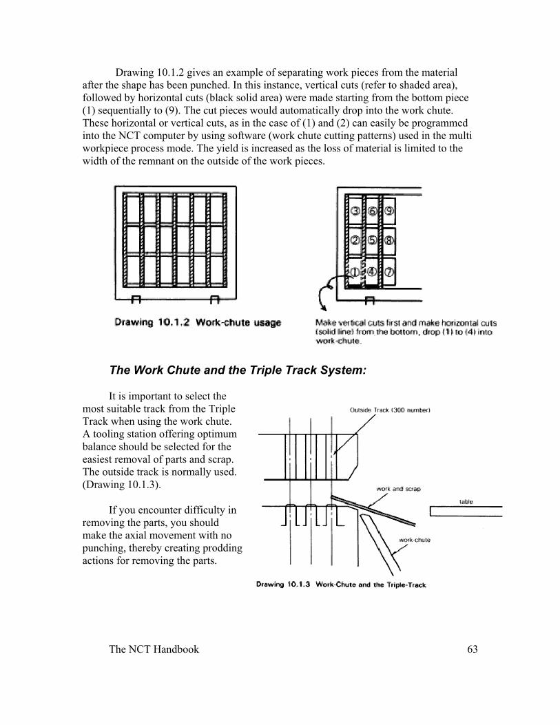
Drawing 10.1.2 gives an example of separating work pieces from the material after the shape has been punched. In this instance, vertical cuts (refer to shaded area), followed by horizontal cuts (black solid area) were made starting from the bottom piece (1) sequentially to (9). The cut pieces would automatically drop into the work chute. These horizontal or vertical cuts, as in the case of (1) and (2) can easily be programmed into the NCT computer by using software (work chute cutting patterns) used in the multi workpiece process mode. The yield is increased as the loss of material is limited to the width of the remnant on the outside of the work pieces.
The Work Chute and the Triple Track System:
It is important to select the most suitable track from the Triple Track when using the work chute. A tooling station offering optimum balance should be selected for the easiest removal of parts and scrap. The outside track is normally used. (Drawing 10.1.3).
If you encounter difficulty in removing the parts, you should make the axial movement with no punching, thereby creating prodding actions for removing the parts.
The NCT Handbook 64
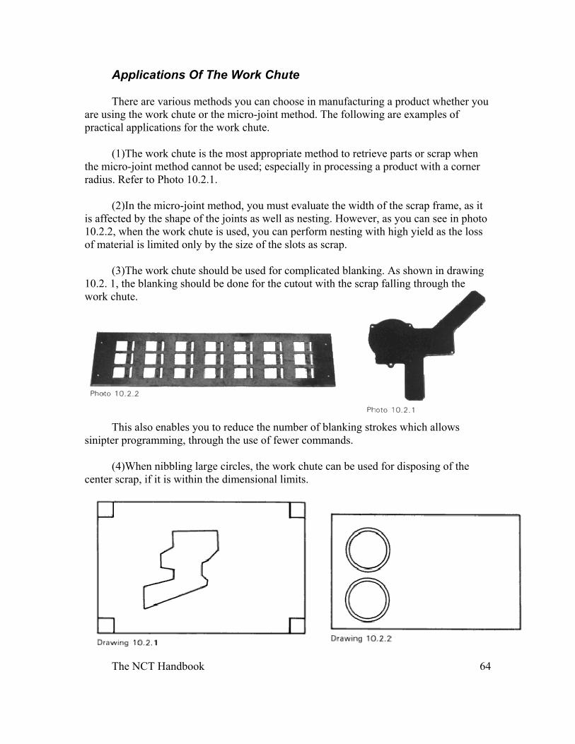
Applications Of The Work Chute
There are various methods you can choose in manufacturing a product whether you are using the work chute or the micro-joint method. The following are examples of practical applications for the work chute.
(1)The work chute is the most appropriate method to retrieve parts or scrap when the micro-joint method cannot be used; especially in processing a product with a corner radius. Refer to Photo 10.2.1.
(2)In the micro-joint method, you must evaluate the width of the scrap frame, as it is affected by the shape of the joints as well as nesting. However, as you can see in photo 10.2.2, when the work chute is used, you can perform nesting with high yield as the loss of material is limited only by the size of the slots as scrap.
(3)The work chute should be used for complicated blanking. As shown in drawing 10.2. 1, the blanking should be done for the cutout with the scrap falling through the work chute.
This also enables you to reduce the number of blanking strokes which allows sinipter programming, through the use of fewer commands.
(4)When nibbling large circles, the work chute can be used for disposing of the center scrap, if it is within the dimensional limits.
The NCT Handbook 65
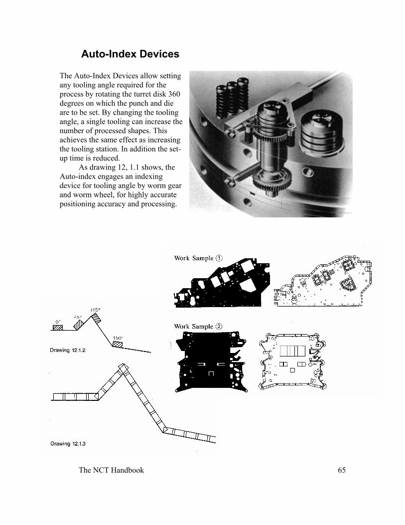
Auto-Index Devices
The Auto-Index Devices allow setting any tooling angle required for the process by rotating the turret disk 360 degrees on which the punch and die are to be set. By changing the tooling angle, a single tooling can increase the number of processed shapes. This achieves the same effect as increasing the tooling station. In addition the set-up time is reduced.
As drawing 12, 1.1 shows, the Auto-index engages an indexing device for tooling angle by worm gear and worm wheel, for highly accurate positioning accuracy and processing.