The Mini-OTDR Modes - Keysightliterature.cdn.keysight.com/litweb/pdf/E6000-91010.pdf · E6000C...
6
E6000C Mini-OTDR Reference Card The Mini-OTDR Modes • OTDR Mode: make, view and analyze traces • Fiber Break Locator: simplified trace setting to locate fiber breaks quickly. • Source Mode: enable the stabilized laser source for loss. If a submodule is installed, this icon is labeled Power Meter or Visual Light. • Instrument Config; set up the Mini-OTDR configuration. • File Utility: internal directory structure of the Mini-OTDR or an added device: copy, delete, or print files. • Easy OTDR: view a trace, perform simple operations, and apply presaved settings. • Multi Fiber Test: measure and define up to 4 measure- ments, and apply all measurements to multiple fibers. • OTDR Assistant: walk through a typical OTDR measure- ment, with hints about which parameters you should adjust. • OTDR Training: general background information about using OTDRs. Connecting a Fiber • Clean the connectors (see below). • Attach the required optical connector interface to the optical output. • Connect the fiber to this interface. • Turn on the Instrument. Cleaning Connectors • Clean the connector by rubbing a new, dry cotton swab over the surface using a small circular move- ment. • Blow away any remaining lint with compressed air.
Transcript of The Mini-OTDR Modes - Keysightliterature.cdn.keysight.com/litweb/pdf/E6000-91010.pdf · E6000C...
E6000C Mini-OTDR Reference Card
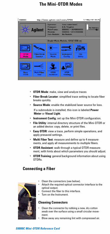
The Mini-OTDR Modes
• OTDR Mode: make, view and analyze traces
• Fiber Break Locator: simplified trace setting to locate fiber breaks quickly.
• Source Mode: enable the stabilized laser source for loss.
If a submodule is installed, this icon is labeled Power Meter or Visual Light.
• Instrument Config; set up the Mini-OTDR configuration.
• File Utility: internal directory structure of the Mini-OTDR or an added device: copy, delete, or print files.
• Easy OTDR: view a trace, perform simple operations, and apply presaved settings.
• Multi Fiber Test: measure and define up to 4 measure-ments, and apply all measurements to multiple fibers.
• OTDR Assistant: walk through a typical OTDR measure-ment, with hints about which parameters you should adjust.
• OTDR Training: general background information about using OTDRs.
Connecting a Fiber
• Clean the connectors (see below).• Attach the required optical connector interface to the
optical output.• Connect the fiber to this interface.• Turn on the Instrument.
Cleaning Connectors
• Clean the connector by rubbing a new, dry cotton swab over the surface using a small circular move-ment.
• Blow away any remaining lint with compressed air.
E6000C Reference Card: E0501 (May 2001)Agilent Product Number E6000-91010
© Agilent Technologies, 2001http://www.agilent.com/comms/OTDR
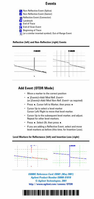
Events
Add Event (OTDR Mode)• Move a marker to the correct position
• ♦ [Events]<Add/Mod Refl. Event>(or [Events]<Add/Mod Non-Refl. Event> as required)
• Press ♦, Cursor left to Marker, then press ♦• Cursor Up to select a level-marker
Cursor Left/Right to move that level-marker.
• Cursor Up to the subsequent level-marker, and adjust.Repeat for other level-markers.
• Press ♦. Select Ok, then press ♦.
• If you are adding a Reflective Event, select and move level-markers as before (this time, for Insertion Loss).
Non-Reflective Event (Splice)Non-Reflective Event (Gainer)
Reflective Event (Connector)LandmarkEnd of TraceEnd-of-Scan EventBeginning of Trace(or a similar inverted symbol): Out-of-Range Event
Reflective (left) and Non-Reflective (right) Events
Level Markers for Reflectance (left) and Insertion Loss (right)
Agilent Technologies
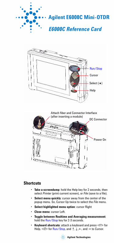
Agilent E6000C Mini-OTDR
E6000C Reference Card
Shortcuts• Take a screendump: hold the Help key for 2 seconds, then
select Printer (print current screen), or File (save to a file).
• Select menu quickly: cursor away from the center of the popup menu. So, Cursor Up twice to select the File menu.
• Select highlighted menu option: cursor Right
• Close menu: cursor Left.
• Toggle between Realtime and Averaging measurement: hold the Run/Stop key for 2-3 seconds.
• Keyboard shortcuts: attach a keyboard and press <f1> for Help, <f2> for Run/Stop, and !,#,$, and & to Cursor.
Run/Stop
Cursor
Select (♦)
Help
Attach fiber and Connector Interface(after inserting a module)
DC Connector
Power On
E6000C Mini-OTDR Reference Card
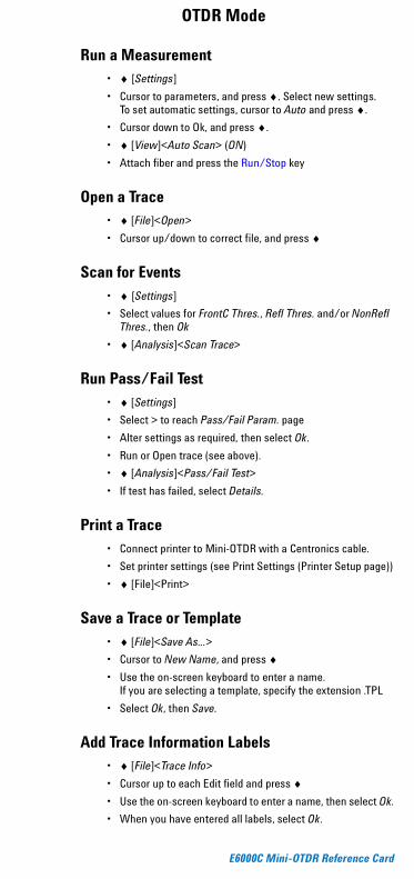
OTDR Mode
Run a Measurement • ♦ [Settings]
• Cursor to parameters, and press ♦. Select new settings.To set automatic settings, cursor to Auto and press ♦.
• Cursor down to Ok, and press ♦.
• ♦ [View]<Auto Scan> (ON)
• Attach fiber and press the Run/Stop key
Open a Trace• ♦ [File]<Open>
• Cursor up/down to correct file, and press ♦
Scan for Events• ♦ [Settings]
• Select values for FrontC Thres., Refl Thres. and/or NonRefl Thres., then Ok
• ♦ [Analysis]<Scan Trace>
Run Pass/Fail Test• ♦ [Settings]
• Select > to reach Pass/Fail Param. page
• Alter settings as required, then select Ok.
• Run or Open trace (see above).
• ♦ [Analysis]<Pass/Fail Test>
• If test has failed, select Details.
Print a Trace• Connect printer to Mini-OTDR with a Centronics cable.
• Set printer settings (see Print Settings (Printer Setup page))
• ♦ [File]<Print>
Save a Trace or Template• ♦ [File]<Save As...>
• Cursor to New Name, and press ♦• Use the on-screen keyboard to enter a name.
If you are selecting a template, specify the extension .TPL
• Select Ok, then Save.
Add Trace Information Labels• ♦ [File]<Trace Info>
• Cursor up to each Edit field and press ♦• Use the on-screen keyboard to enter a name, then select Ok.
• When you have entered all labels, select Ok.
E6000C Mini-OTDR Reference Card
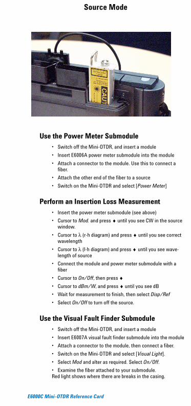
Source Mode
Use the Power Meter Submodule• Switch off the Mini-OTDR, and insert a module
• Insert E6006A power meter submodule into the module
• Attach a connector to the module. Use this to connect a fiber.
• Attach the other end of the fiber to a source
• Switch on the Mini-OTDR and select [Power Meter]
Perform an Insertion Loss Measurement• Insert the power meter submodule (see above)
• Cursor to Mod. and press ♦ until you see CW in the source window.
• Cursor to λ (r-h diagram) and press ♦ until you see correct wavelength
• Cursor to λ (l-h diagram) and press ♦ until you see wave-length of source
• Connect the module and power meter submodule with a fiber
• Cursor to On/Off, then press ♦• Cursor to dBm/W, and press ♦ until you see dB
• Wait for measurement to finish, then select Disp/Ref
• Select On/Off to turn off the source.
Use the Visual Fault Finder Submodule• Switch off the Mini-OTDR, and insert a module
• Insert E6007A visual fault finder submodule into the module
• Attach a connector to the module, then connect a fiber.
• Switch on the Mini-OTDR and select [Visual Light].
• Select Mod and alter as required. Select On/Off.
• Examine the fiber attached to your submodule. Red light shows where there are breaks in the casing.
E6000C Mini-OTDR Reference Card
Other Mini-OTDR Modes
Test for Fiber Break (Fiber Break Locator mode)• Select parameters (Refr Ind, Wavelength, Threshold), and
alter as required
• Attach fiber and press Run/Stop
• Wait for Averaging Time to elapse, or press Run/Stop again.
Test Multiple Fibers (Multi Fiber Test mode)• Select > until you see the Measurement Params page.
• Cursor to Measurements edit field(s) and press ♦
• Select trace or template containing settings
• Press [Start]
• Connect first fiber, then select Ok
• Wait for Averaging Time to elapse, or press Run/Stop.
• Connect the next fiber, then select Ok.
• Continue until all fibers have been measured.
Copy file from Floppy Disk (File Utility mode)• Insert a floppy disk containing your file
• [Device]<Floppy>
• Cursor to file and press ♦
• Select file, then Copy.
• Select [Device]<Internal> then Ok.
Instrument Config Mode
Add a logo (General Parameters page)
• Copy your logo (as PCX file) to your Mini (see above)
• [Logo]<Select>
• Cursor down to your logo name, and press ♦• Select Save, then OK.
Connect to PC (Instrument Setup page)
• Attach your PC to an OTDR with a serial cable
• Select correct settings, select Save, then OK.
Set User Experience Level (General Parameters page)
• Cursor to User Experience Level
• Select Low to see the Fiber Break Assistant in Fiber Break Locator modeSelect High to hide the Fiber Break Assistant
• Select Save, then OK.
Print Settings (Printer Setup page)
• Select correct settings, select Save, then OK.