THE METROPOLITAN SEWER DISTRICT OF GREATER …msdgc.org/cip/2005/downloads/Copy of...
45
Page 1 of 32 Addendum 2 THE METROPOLITAN SEWER DISTRICT OF GREATER CINCINNATI CINCINNATI, OHIO 45204 MILL CREEK WWTP INCINERATOR REPLACEMENT, PHASE 2 CONTRACT 68 PROPOSED SANITARY SEWER NO. 5565p2 CIP. NO. 2004-10 ADDENDUM NO. 2 March 2, 2007 This addendum will only be distributed via e-mail, but will remain available for viewing on the MSD website at www.MSDGC.org . No hard copy will follow. Any questions you may have on the information contained in this addendum should be directed to the MSD Project Manager, William Lutz at (513) 244-5102. NOTE: Please be sure to enter the TOTAL NUMBER of Addenda issued on the Contract contained in the Bidding Booklet prior to submitting your bid. The attention of all bidders is directed to the following additions and/or deletions to the Contract Documents. CHANGED ITEMS are HIGHLIGHTED and UNDERLINED The Contract Documents for the above referenced project are amended and revised as follows: INVITATION TO BID BOOKLET COVER (VOLUME I, II, III and IV) 1. REPLACE “BIDS TO OPEN AT 1:30 PM ON: 3/6/2007 ” with the following: “BIDS TO OPEN AT 1:30 PM ON: 3/27/2007 ” VOLUME I 1. Legal Notice, page 3: REPLACE “SEALED BIDS will be received at the Metropolitan Sewer District of Greater Cincinnati (MSDGC): UNTIL 1:30 PM, on Tuesday, March 6 , 2007” with the following: “SEALED BIDS will be received at the Metropolitan Sewer District of Greater Cincinnati (MSDGC): UNTIL 1:30 PM, on Tuesday, March 27 , 2007”
Transcript of THE METROPOLITAN SEWER DISTRICT OF GREATER …msdgc.org/cip/2005/downloads/Copy of...

Page 1 of 32 Addendum 2
THE METROPOLITAN SEWER DISTRICT OF GREATER CINCINNATI CINCINNATI, OHIO 45204
MILL CREEK WWTP INCINERATOR REPLACEMENT, PHASE 2
CONTRACT 68 PROPOSED SANITARY SEWER NO. 5565p2
CIP. NO. 2004-10
ADDENDUM NO. 2
March 2, 2007 This addendum will only be distributed via e-mail, but will remain available for viewing on the MSD website at www.MSDGC.org. No hard copy will follow. Any questions you may have on the information contained in this addendum should be directed to the MSD Project Manager, William Lutz at (513) 244-5102. NOTE: Please be sure to enter the TOTAL NUMBER of Addenda issued on the Contract contained in the Bidding Booklet prior to submitting your bid. The attention of all bidders is directed to the following additions and/or deletions to the Contract Documents.
CHANGED ITEMS are HIGHLIGHTED and UNDERLINED The Contract Documents for the above referenced project are amended and revised as follows: INVITATION TO BID BOOKLET COVER (VOLUME I, II, III and IV)
1. REPLACE “BIDS TO OPEN AT 1:30 PM ON: 3/6/2007” with the following:
“BIDS TO OPEN AT 1:30 PM ON: 3/27/2007” VOLUME I
1. Legal Notice, page 3:
REPLACE “SEALED BIDS will be received at the Metropolitan Sewer District of Greater Cincinnati (MSDGC): UNTIL 1:30 PM, on Tuesday, March 6, 2007” with the following: “SEALED BIDS will be received at the Metropolitan Sewer District of Greater Cincinnati (MSDGC): UNTIL 1:30 PM, on Tuesday, March 27, 2007”

Page 2 of 32 Addendum 2
2. Legal Notice, page 3, third paragraph, first sentence:
REPLACE “The Contractor shall complete the work within Thirty-Four (34) months of the “Notice to Proceed” date and shall complete start-up and commissioning of all fluid bed incinerator systems within Twenty-Four (24) months of the “Notice to Proceed” date.” with the following: “The Contractor shall complete the work within Forty-Two (42) months of the “Notice to Proceed” date and shall complete start-up and commissioning of all fluid bed incinerator systems within Thirty (30) months of the “Notice to Proceed” date.”
3. Instruction to Bidders, page 8, Contract Award: ADD the following sentence to the Contract Award paragraph: “The following post bid submittal is required before award of contract: Subcontractor Contract Bond as required in Section 11920, 3-6.”
4. Invitation to Bid, page 203, fourth paragraph:
REPLACE “It is further understood and agreed that the contractor shall complete the work within Thirty-Four (34) months of the “Notice to Proceed” date and shall complete start-up and commissioning of all fluid bed incinerator systems within Twenty-Four (24) months of the “Notice to Proceed” date.” with the following: “It is further understood and agreed that the contractor shall complete the work within Forty-Two (42) Months of the “Notice to Proceed” date and shall complete start-up and commissioning of all fluid bed incinerator systems within Thirty (30) Months of the “Notice to Proceed” date.”
5. Contract, page 224, fourth paragraph, first sentence: REPLACE “The Contractor shall commence work under this contract on or before the date to be specified in a written order from the City of Cincinnati and shall have the work completed within Thirty-Four (34) Months of the “Notice to Proceed” date and shall complete start-up and commissioning of all fluid bed incinerator systems within Twenty-Four (24) Months of the “Notice to Proceed” date.” with the following: “The Contractor shall commence work under this contract on or before the date to be specified in a written order from the City of Cincinnati and shall have the work completed within Forty-Two (42) Months of the “Notice to Proceed” date and shall complete start-up and commissioning of all fluid bed incinerator systems within Thirty (30) Months of the “Notice to Proceed” date.”

Page 3 of 32 Addendum 2
VOLUME II – DETAILED PROVISIONS 1. Section 01015, paragraph 1.01.01:
REPLACE the fourth paragraph with the following: “The CONTRACTOR under Part 1 shall install all anchors, sleeves, hangers, inserts, and accessories required for Parts 2 – 5 CONTRACTOR into new construction that includes but is not limited to new concrete and masonry. The CONTRACTOR under Parts 2 – 5 shall furnish all such items and necessary setting drawings for such items to the Part 1 CONTRACTOR to be embedded in concrete or masonry and the CONTRACTOR under Part 1 shall be responsible for their proper location. The CONTRACTOR under Parts 2 – 5 are responsible for installing such items required under their contracts attaching to or related to existing structures.”
2. Section 01015, paragraph 1.01.01, page 3:
REPLACE item f. with the following: “All anchor bolts in new construction including but not limited to new concrete and masonry shall be installed by CONTRACTOR under Part 1 and furnished by CONTRACTOR under the appropriate Part, unless specified otherwise.”
3. Section 07160,
ADD Section 07160 – Dampproofing attached.
4. Section 07210, paragraph 2-1.01., third sentence:
REPLACE “Insulation shall cover the underside of the roof completely.” with the following: “Insulation at the interior roof shall be friction fit between roof framing.”
5. Section 07210, page 4:
ADD the following paragraph: “2-6. RIGID ROOF INSULATION FOR STANDING SEAM ROOF. 2-6.01. Composite Roof Insulation. Composite board with ½ inch minimum perlite board bonded to polyisocyanurate foam with opposite side faced with glass fiber felts; minimum thickness 3 ½ inches, R Value – 21.1 per LTTR; ASTM C1289, Type III.
Apache “Millox” GAF “Isotherm Composite”
Johns Manville “ENERGY 2””

Page 4 of 32 Addendum 2
6. Section 07210, page 7:
ADD the following paragraph:
“3-4.01. Rigid Roof Insulation for Standing Seam Roof. Insulation shall be dry when installed. No more insulation shall be installed than can be covered with roofing membrane before the end of the day's work or before the onset of inclement weather. Unless otherwise specified, insulation shall be laid over the substrate, with joints no wider than 1/4 inch. Joints wider than 1/4 inch shall be filled with the same insulation. Insulation boards shall be laid with joints staggered between parallel courses and, if required, between layers. Abutting edges of boards shall be laid in moderate contact, not forced into place. At vertical surfaces, insulation shall be cut neatly to provide a clearance of not more than 1/4 inch. The insulation shall be anchored to the metal roof deck with mechanical fasteners in accordance with FM Bulletin 1-28 and the FM Approval Guide. Installation of the mechanical fasteners shall be in accordance with the manufacturer's recommendations.”
7. Section 07535, pages 3 and 4:
REPLACE Section 07535, pages 3 and 4 with the attached. 8. Section 08130:
ADD Section 08130 – Steel Doors and Frames attached.
9. Section 11920, 3-6: REPLACE paragraph 3-6. with the following: “3-6. GUARANTEES AND BONDS. In addition to guarantee requirements in the General Equipment Stipulations, and the performance and design requirements as set forth in other sections of this specification, the SUPPLIER shall guarantee that the equipment will be capable of the following: Continuous incinerator operations with planned unit outages for normal maintenance not to exceed 7 days per year. Reactor heating and cooling is not to be included in this time. Incineration of biosolids with variation in moisture and volatile content (as specified) without major changes in operating techniques or system operating characteristics. If the fluid bed incinerator system fails to comply with these requirements, failed components shall be repaired or replaced at no cost to the OWNER.

Page 5 of 32 Addendum 2
In addition, the SUPPLIER shall furnish the completed Subcontractor Contract Bond located at the end of this section.”
10. Section 11920, Subcontractor Contract Bond:
INSERT the attached Subcontractor Contract Bond following Section 11920. VOLUME III - DETAILED PROVISIONS 1. Section 13560-1 (Device List), page 7:
Item 77 Device Type REPLACE “Magnetic Flowmeter, Signal Converter” with the following: “Positive Displacement Flowmeter, Signal Converter”
2. Section 13560-1 (Device List), page 7:
Item 79 Device Type REPLACE “Magnetic Flowmeter, Signal Converter” with the following: “Positive Displacement Flowmeter, Signal Converter”
3. Section 13560-1 (Device List), page 7:
Item 81 Device Type REPLACE “Magnetic Flowmeter, Signal Converter” with the following: “Positive Displacement Flowmeter, Signal Converter”
4. Section 16343, 1-1:
REPLACE paragraph 1-1. SCOPE with the following: “1-1. SCOPE. This section covers the complete off-site rebuild and reconditioning of the 5KV GE MagneBlast circuit breakers being utilized to serve the new 5KV MCLU, including both mains and the bus-tie breaker in the 5KV switchgear lineup.”
5. Section 16343,1-2:
REPLACE paragraph 1-2. GENERAL with the following: “1-2. GENERAL. The equipment covered includes the two circuit breakers located in the generator building 5KV switchgear lineup. These two breakers are presently designated Units 53 and 62. Also included are both mains: 51 and 61, and the bus-tie breaker 57.”

Page 6 of 32 Addendum 2
DRAWINGS 1. D102, Elevation:
REPLACE “SAWCUT CONC BASE 1’-0” BELOW GRADE AND BACKFILL (TYPE)” with the following: “REMOVE CONC BASE 1’-0” BELOW GRADE AND BACKFILL (TYPE)”
2. D701, MH Incinerator Building – Demolition Notes:
REMOVE the following note:
“6. ALL REMAINING HOLES ON THE BASE SLAB SHALL BE CLOSED OFF FOR A WATERTIGHT CLOSURE”
3. D702, Notes:
ADD the following note: “4. CORE 10 INCH DIAMETER HOLES THROUGH BASE SLAB TO BE BACKFILLED. A MINIMUM OF 30 HOLES SHALL BE PROVIDED EVENLY SPACED ACROSS SLAB.”
4. S315, Section 2:
REMOVE south column line “16.2”.
5. S315, Section 2:
MOVE north column line “16.2” south approximately 8” north of the north face of pile cap for IPHE-3.
6. A101, 2005 Ohio Building Code table: ADD the following to the 2005 Ohio Building Code table: “UL Design U904 (3 hour) Classification C-3 UL Design U905 (2 hour) Classification C-3 UL Design U905 (1 hour) Classification D-2 Concrete Block used for fire-rated masonry walls shall conform to UL 618 Standards.”
7. A311, scale:
REPLACE “3/16” = 1’0” with the following: “1/8” = 1’0”

Page 7 of 32 Addendum 2
8. A311:
REPLACE section bubbles “F/A908” with the following: “E/A908”
9. A311:
REPLACE “WALKWAY MANUFACTURER STANDARD, (TYPICAL)” with the following: “WALKWAY SHALL BE DESIGNED AND FURNISHED BY STANDING SEAM ROOF MANUFACTURER”
10. A314, Section 3:
REPLACE reference to “A307” with the following: “A303”
11. A316, Enlarged Stair Plan @ EL 473.50:
REPLACE “1 HOUR” with the following: “2 HOUR”
12. A316, Enlarged Stair Plan @ EL 492.00: REPLACE “1 HOUR” with the following: “2 HOUR”
13. A317, Enlarged Stair Plan @ EL 509.50:
REPLACE “1 HOUR” with the following: “2 HOUR”
14. A317, Enlarged Stair Plan @ EL 532.00: REPLACE “1 HOUR” with the following: “2 HOUR”
15. A318, Stair Section 1/A316, A317:
ADD to the masonry wall located at column line 12.8 the following hour wall rating: “2 HOUR”

Page 8 of 32 Addendum 2
16. A318, Stair Section 1/A316, A317:
ADD to the concrete wall located at column line 18.1 the following hour wall rating: “2 HOUR”
17. A402, Floor Plan EL 509.50:
ADD the following hour wall rating to the masonry walls (North, East and West) that surround Stair 453: “1 HOUR”
18. A501, Floor Plan EL 473.50:
ADD to the concrete wall located at column line 18.1 the following hour wall rating: “2 HOUR”
19. A901, Door Schedule:
Incinerator Building – North – EL 473.50, Door 301, Door Type REPLACE “FRP” with the following: “HM”
20. A901, Door Schedule:
Incinerator Building – North – EL 473.50, Door 301, Frame Type REPLACE “FRP” with the following: “HM”
21. A901, Door Schedule:
Incinerator Building – North – EL 473.50, Door 301, Fire Rated REPLACE “1 HOUR” with the following: “2 HOUR”
22. A901, Door Schedule:
Incinerator Building – North – EL 473.50, Door 303, Door Type REPLACE “FRP” with the following: “HM”
Page 9 of 32 Addendum 2
23. A901, Door Schedule:
Incinerator Building – North – EL 473.50, Door 303, Frame Type REPLACE “FRP” with the following: “HM”
24. A901, Door Schedule:
Incinerator Building – North – EL 492.00, Door 314, Door Elevation REPLACE “D” with the following: “A”
25. A901, Door Schedule:
Incinerator Building – North – EL 492.00, Door 314, Fire Rated REPLACE “2 HOUR” with the following: “3 HOUR”
26. A901, Door Schedule:
Incinerator Building – North – EL 492.00, Door 314, Remarks REMOVE “WIRE GLASS”
27. A901, Door Schedule:
Incinerator Building – North – EL 492.00, Door 315, Door Type REPLACE “FRP” with the following: “HM”
28. A901, Door Schedule:
Incinerator Building – North – EL 492.00, Door 315, Frame Type REPLACE “FRP” with the following: “HM”
29. A901, Door Schedule:
Incinerator Building – North – EL 492.00, Door 315, Fire Rated REPLACE “1 HOUR” with the following: “2 HOUR”

Page 10 of 32 Addendum 2
30. A901, Door Schedule:
Incinerator Building – North – EL 492.00, Door 316, Fire Rated REPLACE “2 HOUR” with the following: “3 HOUR”
31. A901, Door Schedule:
Incinerator Building – North – EL 492.00, Door 318, Fire Rated ADD the following: “1 HOUR”
32. A901, Door Schedule:
Incinerator Building – North – EL 492.00, Door 319, Door Elevation REPLACE “D” with the following: “A”
33. A901, Door Schedule:
Incinerator Building – North – EL 492.00, Door 319, Remarks REMOVE “WIRE GLASS”
34. A901, Door Schedule:
Incinerator Building – North – EL 492.00, Door 320, Door Elevation REPLACE “D” with the following: “A”
35. A901, Door Schedule:
Incinerator Building – North – EL 492.00, Door 320, Fire Rated REPLACE “2 HOUR” with the following: “3 HOUR”
36. A901, Door Schedule:
Incinerator Building – North – EL 492.00, Door 320, Remarks REMOVE “WIRE GLASS”
37. A901, Door Schedule:
Incinerator Building – North – EL 492.00, Door 321, Door Elevation REPLACE “D” with the following: “A”
Page 11 of 32 Addendum 2
38. A901, Door Schedule:
Incinerator Building – North – EL 492.00, Door 321, Fire Rated REPLACE “2 HOUR” with the following: “3 HOUR”
39. A901, Door Schedule:
Incinerator Building – North – EL 492.00, Door 321, Remarks REMOVE “WIRE GLASS”
40. A901, Door Schedule:
Incinerator Building – North – EL 509.50, Door 351, Door Elevation REPLACE “B” with the following: “A”
41. A901, Door Schedule:
Incinerator Building – North – EL 509.50, Door 351, Fire Rated REPLACE “2 HOUR” with the following: “3 HOUR”
42. A901, Door Schedule:
Incinerator Building – North – EL 509.50, Door 351, Remarks REMOVE “WIRE GLASS”
43. A901, Door Schedule:
Incinerator Building – North – EL 509.50, Door 352, Door Type REPLACE “FRP” with the following: “HM”
44. A901, Door Schedule:
Incinerator Building – North – EL 509.50, Door 352, Frame Type REPLACE “FRP” with the following: “HM”
45. A901, Door Schedule:
Incinerator Building – North – EL 509.50, Door 352, Fire Rated REPLACE “1 HOUR” with the following: “2 HOUR”

Page 12 of 32 Addendum 2
46. A901, Door Schedule:
Incinerator Building – North – EL 509.50, Door 353, Fire Rated REPLACE “2 HOUR” with the following: “3 HOUR”
47. A901, Door Schedule:
Incinerator Building – North – EL 509.50, Door 356, Door Elevation REPLACE “D” with the following: “A”
48. A901, Door Schedule:
Incinerator Building – North – EL 509.50, Door 356, Remarks REMOVE “WIRE GLASS”
49. A901, Door Schedule:
Incinerator Building – North – EL 509.50, Door 357, Door Elevation REPLACE “D” with the following: “A”
50. A901, Door Schedule:
Incinerator Building – North – EL 509.50, Door 357, Remarks REMOVE “WIRE GLASS”
51. A901, Door Schedule:
Incinerator Building – North – EL 532.00, Door 371, Fire Rated REPLACE “1 HOUR” with the following: “2 HOUR”
52. A901, Door Schedule:
Incinerator Building – North – EL 532.00, Door 373, Door Elevation REPLACE “D” with the following: “A”
53. A901, Door Schedule:
Incinerator Building – North – EL 532.00, Door 373, Remarks REMOVE “WIRE GLASS”

Page 13 of 32 Addendum 2
54. A901, Door Schedule:
Incinerator Building – South – EL 509.50, Door 452, Fire Rated ADD the following: “1 HOUR”
55. A901, Door Schedule:
Incinerator Building – South – EL 509.50, Door 452, Remarks ADD the following: “WIRE GLASS”
56. A901, Door Schedule:
Incinerator Building – South – EL 509.50, Door 453, Fire Rated ADD the following: “1 HOUR”
57. A901, Door Schedule:
Incinerator Building – South – EL 509.50, Door 453, Remarks ADD the following: “WIRE GLASS”
58. A901, Door Schedule:
Incinerator Building – South – EL 492.00, Door 413, Fire Rated ADD the following: “2 HOUR”
59. A901, Door Schedule:
Incinerator Building – South – EL 492.00, Door 413, Remarks ADD the following: “WIRE GLASS, EXTERIOR DOOR”
60. A906, Detail A, C, D, F, G, H:
REPLACE “ROOF INSULATION” with the following: “3 ½” ROOF INSULATION”
61. A910, Detail M, N:
REPLACE “ROOF INSULATION” with the following: “3 ½” ROOF INSULATION”

Page 14 of 32 Addendum 2
62. PI205:
REPLACE “FUEL OIL INJECTORS (TYP OF 8)” with the following: “FUEL OIL INJECTORS (TYP OF 10)”
63. PI205:
REPLACE “NATURAL GAS INJECTORS (TYP OF 16)” with the following: “NATURAL GAS INJECTORS (TYP OF 20)”
64. PI209:
REPLACE “FUEL OIL INJECTORS (TYP OF 8)” with the following: “FUEL OIL INJECTORS (TYP OF 10)”
65. PI209:
REPLACE “NATURAL GAS INJECTORS (TYP OF 16)” with the following: “NATURAL GAS INJECTORS (TYP OF 20)”
66. PI213:
REPLACE “FUEL OIL INJECTORS (TYP OF 8)” with the following: “FUEL OIL INJECTORS (TYP OF 10)”
67. PI213:
REPLACE “NATURAL GAS INJECTORS (TYP OF 16)” with the following: “NATURAL GAS INJECTORS (TYP OF 20)”
68. P301:
Along column line 18, REPLACE “SEE SH PE701 FOR CONT” with the following: “3” DRAIN LINE SHALL BE EXTENDED TO THE SUMP IN THE TUNNEL NEAR COLUMN LINE R”
69. E403:
ADD four (4) new exit signs (fixture type “EXIT”). Install new exit light over door D356, D357, D454 and D455.

Page 15 of 32 Addendum 2
70. E403:
ADD the following note: “5. REMOVE ANY EXISTING EXIT LIGHTS ASSOCIATED WITH THE DOORS INTO STAIR 453.”
71. E910,
INSERT attached Figure E910-1.

Page 16 of 32 Addendum 2
PRE-BID MEETING MINUTES Meeting: Pre-Bid Meeting Project: Mill Creek Incinerator Replacement, Phase 2 Date: February 15, 2007 Time: 1:30 PM Location: Mill Creek WWTP Old Administration Building Lunch Room
Purpose To address Bidders’ questions on the Contract Documents for Mill Creek WWTP Incinerator Replacement, Phase 2. Attending
Name Organization
Rick Anderschat MSD
Len Bauer MSD
Laura Brown MSD
Mike Heitz MSD
Bill Lutz MSD
Scott Maring MSD
Mary Mount MSD
John Shinn MSD
Mark Steinmetz MSD
Dave West MSD
Gloria Williams MSD
Timo Bungert AEE – Von Roll
Robert Waite Rona Construction Co.
Raymond Rona Construction Co.
Tony Brice LIUNA Local 265
Joe Eichler Cleveland Wrecking Company
Mike Mathews Cleveland Wrecking Company
John Rico Kokosing Construction Company, Inc.
Mark Littleton Kokosing Construction Company, Inc.
Gene Heidel King Wrecking Company Inc.

Page 17 of 32 Addendum 2
James Rapp Ulliman Schutte
Trent Bledsoe Ulliman Schutte
Wally Gore DeBra-Kuempel
Marshall Sidwell DeBra-Kuempel
Mike Mullen Wagner Industrial
Tim O’Meara Wagner Industrial
Jeff Berning Reynolds Inc.
John Griffith Reynolds Inc.
Devin Baker Reynolds Inc.
Eric Herschelman Reynolds Inc.
Ted Wagner Reynolds Inc.
Ky Dangtran IDI
Merv Bowen IDI
Laura Tegethoff Smith Environmental Inc.
Ed Lizak O’Rourke
Steve Thaman Glenwood Electric
Carmen Roeu Ohio LECET
Troy Wagner Sheet Metal 24
Mike Clare Ameridian
Ted Leugers Simplex/Grinnell
Brad Fread Madison Co.
Dennis Brodbeck Scherzinger Drilling
Michael Griffie M-Pact Corporation
Walter Davis Davis Marble & Tile Company
Dwayne Kinsey Davis Marble & Tile Company
Eric Scheidt Delta Electric
Bill Seibert Langdon Inc
Jeff Beiting Lake Erie Electric, Inc.
Joe Mellon Shook Inc.
Eric Rees Shook Inc.
Melissa Moening Black & Veatch
Scott Reed Black & Veatch

Page 18 of 32 Addendum 2
Discussion Items: 1) Introductions
• Laura Brown will be handling all wage rate inquiries. Wage rates in bid booklet are valid for a 90 day period. Most recent wage rates can be found by going to www.msdgc.org and going to the bid booklet of a current construction contract on sale. Laura will check to make sure contractors are paying the correct wage rates. Contractor must submit the 257, The Monthly Minority Utilization Report by the tenth of the month. It should reflect construction project workforce for all jobs that your company is working on in Hamilton County. The report should be submitted monthly by all primes and sub-contractors for MSDGC projects. The goals are the same for primes and subs. The EEO Minority goals are: Minority Male – 11.8% Minority Female 3.45%, Majority Female (White) 3.45% – Total Female – 6.9% for all MSDGC jobs.
• Gloria Williams will be handling all SBE inquiries. SBE requirements changed in Addendum 1. According to Addendum 1, MSD has set the overall SBE Participation Goal for this project at 12%. If the General, HVAC, Plumbing, and Electrical are awarded separately, the SBE participation goal for each will be General 10%, HVAC 20%, Plumbing 15%, and Electrical 20%. There is no SBE goal set for the Elevator portion of the contract; however, the bidder must submit an SBE inclusion plan for any portion of the elevator work that may be subcontracted.
• Bill Lutz is the Project Manager for MSD. • Scott Reed and Melissa Moening are the engineers on the project from Black &
Veatch. All separate inquiries can be emailed to Scott Reed at [email protected]. 2) Bid Booklet
• Bid opening will be delayed three weeks. The new bid opening will be March 27, 2007. Refer to page 1, item number 1 in this addendum.
• All questions regarding prevailing wages shall be addressed to Laura Brown. • All questions regarding SBE participation goals shall be addressed to Gloria
Williams. If Contractors need contacts of SBEs, Gloria can provide assistance. SBEs can be from anywhere as long as they can provide SBE verification. SBEs do not have to be authorized from the City of Cincinnati or the State of Ohio.
3) Project Description
• New Incinerator Building (Phase 1) will house the new incinerator equipment. • The north portion of the Thermal Conditioning Building will be demolished to
accommodate the new Incinerator Building. The south portion of the Thermal Conditioning Building will be modified to house the new blower equipment and electrical equipment for the incinerators. The existing concrete tanks will be converted into rooms containing various equipment and piping (Phase 1). Lead paint removal in Thermal Conditioning Building is only for portion of building to be maintained. Proper precautions shall be taken during demolition of north portion of Thermal Conditioning Building.
• Dewatering building modifications will include converting the dewatering pumps from single discharge to dual discharge. Also, the control room will be expanded and a restroom and break room will be added.
• Existing Incinerator Building and equipment will be demolished (Phase 2). No equipment or material is to be salvaged. Phase 1 Environmental Assessment of existing Incinerator Building will be performed prior to award of bids.

Page 19 of 32 Addendum 2
4) Project Schedule
• The duration for start-up and commissioning of new incinerators will be extended by 6 months from the original twenty-four (24) months. The duration of overall completion will be extended by 8 months from the original Thirty-Four (34) months. Refer to page 2, item numbers 2, 4 and 5 in this addendum.
• MSD has pre-purchased substation and switchgear and are expecting delivery in August or September. This equipment will be installed by the Part 4 Contractor during Phase 1.
5) Construction Sequence
• Black & Veatch has provided a suggested sequence for construction operations in Section 01310.
• Demolish gas storage spheres. • Substation demolition, temporary power, and standby generator relocation. • Access to existing incinerator building and receiving building. • Install piping in basement of existing incinerator building prior to tunnel
construction. Piping may have to be temporarily supported during construction of tunnel.
• Prepare temporary workstations in office adjacent to control room during modifications. MSD has their own IT group to assist with temporary workstations.
• Modify west bank of dewatered solids pumps near end of Phase 1 construction. • Complete performance testing of all fluid bed incinerators prior to Phase 2
construction.
6) Addenda • Addendum 1 was issued February 14, 2007. • Addendum 2 will be issued during the week of February 26, 2007. Addendum 2
will cover pre-bid meeting minutes, contractor questions, and any other changes/modifications.
7) Questions / Comments
The following questions were posed by the Bidders at the Pre-Bid Meeting. These questions/comments have been added to the Bidders Questionnaire included in the addendum. • What is the thickness of steel on the gas storage spheres? • Does General get credit for SBE Contractors assigned to him following award
of bid? • Aware of any other hazards beyond asbestos in MH Incinerator Building? • Who is responsible for Phase 1 environmental assessment prior to demolition
in MH Incinerator Building? • Can Contractor charge his time for tasks associated with Asset Management
allowance? • Does anything need to be provided at bid for Asset Management? • How are manufacturers/suppliers that are not base bid evaluated? • Is it possible to require pass-through bonding for the Incinerator Equipment
from manufacturer directly to Owner or possibly a re-insurance type arrangement for a portion of the General Contractor’s bond?

Page 20 of 32 Addendum 2
• Request Contractor for Part 4 to gain knowledge of scope of supply for electrical items from Incinerator Manufacturer (IDI).
• Can other demolition methods be used for Dewatering Building slab other than hydro-demolition?
• Is vibration during Thermal Conditioning demolition and placing of piles a concern?
• Is the Part 1 Contractor responsible for installation of sleeves and anchors in existing concrete and masonry for work applicable to the Parts 2 - 5 Contractors?
8) Project Site Tour

Page 21 of 32 Addendum 2
BIDDERS’ QUESTIONS
1. Please review Section 03350 after article 3-9. I see no mention of any rub finish. What type of finish do the walls of the tunnel receive? The concrete ceiling of the tunnel? No rub finish is required. See Section 03350, paragraph 3-8 for finish of formed surfaces.
2. To what structure or structures does Section 03710 apply? This is difficult to quantify, can we get an allowance so all contractors are bidding the same thing? Section 03710 generally applies to areas where work will be performed under this Contract. Concrete crack repair is not covered under an allowance.
3. Section 6 on sheet S302, does this condition only apply to piles G8, G14-G16? Please clarify. Section 6 on S302 applies only to piles G8, G14, G15 and G16. The 4’-0” diameter holes for piles G8, G14, G15, G16 may be combined into a single opening approximately 4’ by 9’.
4. S301, is there a new pile cap being installed over proposed piles A26, A18 and B12? There is no pile cap over piles A26, A18 and B12. It will be reinforced similar to Section 3 on S302.
5. Is there any coating that gets applied to the existing mat prior to the placement of the new mat on top of it? Specification Section 03350 does not require a coating (i.e. bonding agent) be applied to hardened concrete which will have fresh concrete placed on or against it. Never the less, a good bond is required per paragraph 3-2.01. An epoxy bonding agent (see Section 03350) may be used if the Contractor deems it is needed to achieve a good bond.
6. Sheet S315, section 2 shows a change in existing mat elevation from 490.75 to 489.75 between two column lines but they are both labeled 16.2. Please review and clarify. Where is this change in mat elevation? The change in existing mat elevation (from 490.75 to 489.75) occurs approximately 3 feet south of column line 16.2. Refer to the plan for column line 16.2 location. The south column line 16.2 on Section 2/S315 should be deleted. The north column line 16.2 on Section 2/S315 should be moved south approximately 8” north of the north face of pile cap for IPHE-3. Refer to page 6, item numbers 4 and 5 for modifications to Section 2 on S315 in this addendum.
7. We would like to request that Badd Inc. of Jeffersonville, IN be added as an approved manufacturer/supplier of handrail under Section 05520. www.baddinc.com The acceptable handrail manufacturers listed in Section 05520 do not represent all acceptable manufacturers and are only intended to establish the type, function and quality required. All handrails will be reviewed as part of the shop drawing submittal.

Page 22 of 32 Addendum 2
8. The demolition spec 02050-3-1.01 b&c anticipates asbestos and lead paint
are present in the MH Incinerator building and that lead paint is present in the Thermal Conditioning Building on the steel columns. Section 01015 is referenced. Section 01015-20 & 21 state the procedures to follow if asbestos or lead paint are found. Section 01015-16 gives an allowance for all removal of asbestos however the allowance for the lead paint removal is only for the 13800 sf on the steel columns. If lead paint is encountered in the MH Incinerator as anticipated or elsewhere in the Thermal Conditioning Bldg, will it be paid for under this allowance, will it be paid for as an extra under the unit price, or are we to add it to our base bid lump sum price? Any lead paint discovered in the MH Incinerator Building and/or portion of the Thermal Conditioning Building to be demolished should not be removed. Lead paint removal is only intended for steel columns and beams in the Thermal Conditioning Building to remain.
9. Section 2 on sheet S315 at column lines A & 11 shows us taking out only the top portion of concrete and not the full depth of the mat. It will be necessary for us to remove the full depth of the mat in order for the APGD piles to be placed. Are we to only cut out a small area full depth at each pile location or can remove full depth the entire column line? The existing concrete at column lines A and 11 may be 1) entirely removed within the width of the thickened edge or 2) locally removed full depth at each pile and a strip the width of the thickened edge removed down to elevation 489.50. The integrity of the existing slab outside the limits of the thickened edge must be maintained.
10. Sheet S303, section 1 shows waterproofing being applied to the top deck of the tunnel on the side exposed to earth. Is there a spec section for this waterproofing? Does the waterproofing apply to the horizontal deck surface and down the outside face of the wall? All exterior concrete surfaces of the tunnel in contact with fill shall be dampproofed. Refer to dampproofing specification section 07160 which is attached with this addendum.
11. Plan sheet P301, 3” drain line along column line A, FD at elev. 487.88: the note calls for you to reference sheet PE701 for the continuation of this line, but find no further detail on sheet PE701. Is the 3” drain line to tie into the 12” drain line in the tunnel? The 3” drain line shall be extended to the sump in the tunnel near column line R. Refer to page 14, item number 68 in this addendum for modification to P301.

Page 23 of 32 Addendum 2
12. In reviewing the sequence of construction, we recognize that the NPW, Fuel Oil, Natural Gas, and Sanitary Drain Line piping/services will need installed to complete the Phase I construction. At the same time, leaving all service and equipment in the basement of the MH Incinerator in place and operable, these lines and tunnel construction can not be started and constructed per the details as shown on PE701 and PE702, until Phase I is complete and operating. Was it your intent for the contractor to make provisions to tap existing services, and to provide temporary means to pipe these services to the New Building without disrupting existing MH incineration operations? Can the contractor locate lines against the south wall face in lieu of installation along new tunnel wall per details sheets PE701 and PE702, if it provides a means to not install temporary pipe or relocate pipe after the tunnel is constructed? NPW, natural gas, fuel oil, and drain piping shall be installed prior to tunnel construction. Temporary supports shall be provided as required to maintain piping. Contractor may provide temporary pipe if deemed necessary. Refer to Addendum 1, page 7, item number 25 for addition of note to drawing PE701. The outside face of the natural gas, fuel oil, and drain piping may be offset up to 18 inches off the face of the east-west tunnel wall if deemed necessary by the Contractor for concrete formwork, etc.. Contractor shall avoid piping conflicts with tunnel roof penetrations (e.g. access hatch, HVAC equipment).
13. Per the demolition spec 02050-3-1.01, all debris shall be removed from the
site. Can we use some of the debris, specifically broken concrete and block as fill in the basement of the MH incinerator building? Debris shall not be used as fill. All debris shall be removed from the site. Granular fill shall be used to fill in the basement of the MH Incinerator Building.
14. Section 2/A312 and 1/A314 has a leader titled ‘Concrete Wall Panel’. Is this the concrete beam on the east and west elevations only that is detailed on 7/S316? Please review and clarify the extent of the beam locations. The concrete wall panel is the concrete beam indicated in sections 2/A312, 1/A314 and 7/S316.
15. Per the elevation on drawing D102, the concrete bases get sawcut down 1 ft below grade. Must these be sawcut or can we just bust them up with a breaker to 1 ft below grade? Sawcutting is not required. Refer to page 6, item number 1 in this addendum for modifications to D102.
16. Sheet S501 and S502, where are section cuts 1-3 taken from? S501 shows the bubble but doesn’t show which direction or at what location the cuts are taken from. Section cuts 1 and 2 are taken through the east-west direction looking north.
17. Sheet S501 section 5, at how many locations do the existing columns get extended? It’s difficult to determine from the plans. Clarification is needed to which section is being referred. There doesn’t seem to be a column in section 5 on sheet S501.

Page 24 of 32 Addendum 2
18. Appears to be discrepancy between the P&ID drawings and the specifications regarding the number of Fluid Bed Incinerator Fuel Oil and Natural Gas Injectors. Specification Section 11920, paragraph 2-3 states that the design requirements are for 10 ea. – fuel oil and 20 ea. – natural gas. The P&ID drawings however note on various drawings, fuel oil injectors (typ of 8), and natural gas injectors (typ of 16). In reviewing the initial scope of supply proposal from the manufacturer, it would appear the number of injectors as they propose to supply matches the specification. Please clarify the drawings notes to indicate whether the numbers are correct or incorrect. Specification Section 11920, paragraph 2-3 stating the design requirements for fuel oil 10 each and natural gas 20 each is correct. The P&IDs shall show fuel oil injectors (typ of 10) and natural gas injectors (typ of 20). Refer to page 14, item numbers 62 – 67 for modifications to P&ID sheets PI205, PI209 and PI213.
19. Sheet A402 shows some concrete wall infills but these are not shown on the structural drawings. Need rebar size and spacing requirements, need section cuts and dimensions to calculate quantities. Please clarify. These walls are CMU walls. See Details A and B on A905. For CMU reinforcing, see reinforcing schedule on Drawing S907. These walls will have to be supported at the top. Use 2 L5x3x3/8 x 6” long at 4’-0” spacing (one each side of CMU wall). Fasten each angle to existing concrete slab using one 3/4” diameter adhesive anchor, 4” embed or field weld to existing steel beam with 3/16” fillet weld on 3 sides of angle as applicable.
20. In reference to sheet SW101 ‘Demolition Legend’ the cross hatching locations for Pavement Replacement is a little misleading. Perhaps wording it Pavement Removal would be appropriate. Sheet SW102 shows the location of the New Pavement and the two obviously don’t match. On sheet SW101, the demolition legend should read pavement removal in lieu of pavement replacement. Refer to Addendum 1, page 4, item number 1 for modification to sheet SW101.
21. Drawing S315, in section 2/S303 the new slab pours on top of the existing slab, and at the extreme left of this section view, the existing slab has a top elevation of 489.75. What are the limits of this step down in the existing slab? Everything I find on the demo and structural drawings depict this slab with a top elevation of 490.30. The concrete floor slab shall be removed to the top of the existing foundation mat (EL 492.00). Sheet S315 correctly shows the elevations of existing mat. Refer to Addendum 1, page 4, item number 5 for modification to sheet D802.
22. Drawing S316, section 7 shows a concrete beam that occurs around the perimeter of the building. This beam is shown again in sections 2 and 3 of drawing A312 and in details 20 and 24 of drawing A904. The beam is shown as all concrete faced with brick on the structural drawings. On the architectural drawings it is depicted as a “wall panel”, and the top portion is exposed on the exterior as if to show a cast stone appearance. Please clarify the discrepancies. Refer to response to question 14.

Page 25 of 32 Addendum 2
23. Victaulic couplings for the dewatered solids piping are not shown in the incinerator bldg, (drg PE302). Vic couplings are shown at every fitting on the DS piping in the dewatering bldg. We understand that some vic couplings will be required at the incinerator bldg, but are all the vic couplings shown on PE502 required? Furthermore, is it a requirement that Victaulic Brand fittings be used, (reference spec section 15066, page 3)? Pipe sections may be shop fabricated. Total length of pipe and fittings used in shop fabricated sections shall not exceed 25 ft. Field welding shall not be permitted. Ends of pipe sections shall be double grooved for use with Victaulic Style 808 couplings with the exception of field make-up pieces, which may be field grooved. Refer to Addendum 1, pages 3 & 4, item numbers 1 and 2 for modifications to Specification Section 15066.
24. PE502, what material should the new centrate drain piping be? The existing is Sch 80 PVC. New centrate drain piping shall be schedule 80 PVC. Refer to Addendum 1, page 6, item number 23 for modification to sheet PE502.
25. PE503, what material are the new screw conveyor drains? Existing is Sch 40 PVC. New screw conveyor drains shall be schedule 40 PVC. Refer to Addendum 1, page 6, item number 24 for modification to sheet PE503.
26. Spec section 01630 and 15065 indicates that fuel oil, propane, and natural gas piping are carbon steel. PE702 indicates DIP, please clarify. Fuel oil, propane, and natural gas piping shall be carbon steel. Refer to Addendum 1, page 7 & 8, item numbers 30, 31, and 32 for modifications to sheet PE702.
27. PE702 indicates compressed air piping to be PVC. Spec 01630 and 15065 indicates that compressed air is steel. Please clarify. Compressed air piping shall be steel. Refer to Addendum 1, page 7, item number 29 for modification to sheet PE702.
28. The new service tunnel that will be built in the basement of the existing incinerator building poses some problems. In order to house and protect the new pipe that will be run through this tunnel, the concrete tunnel walls and ceiling need to be constructed while the existing incinerators are still in operation. The problem is that the new tunnel walls/ceiling runs through incinerators 1, 2, and 3. Can MSD run on 3 incinerators? NPW, natural gas, fuel oil, and drain piping shall be installed prior to tunnel construction. Temporary supports shall be provided as required to maintain piping. Refer to Addendum 1, page 7, item number 25 for addition of note to drawing PE701.

Page 26 of 32 Addendum 2
29. Another item that poses an issue is the stair tower on the west side of the existing incinerator building. Although it appears that this tower does not interfere with the new incinerator bldg, or stacks, once the new building structural steel starts to be erected, there is only 2’ between the existing tower and the new building (and both of these structures are over 50’ tall). So access to install the architectural items, i.e. (louvers, windows, metal wall panels, fascia, etc) on the east elevation of the new building will not be available. Perhaps it would be prudent to note in addendum that this stairwell may need to be demolished, and the opening protected at the start of the project. The stairwell shall remain in service during construction of new Incinerator Building and temporary access to the stairwell shall be provided as required. Refer to Addendum 1, page 4, item number 4 for modifications to drawing D101.
30. Incinerator Stack Specification Section 11922 does not specify the following: any minimum required stack shell thickness and any required corrosion allowance. Incinerator Stack shall be designed by stack supplier as specified in Section 11922. The stacks are single wall stacks and likely to have variable thickness, with thick plate near the base and thinner plate near the top. Minimum thickness would be as required for design conditions and shall include corrosion allowance of 0.0625 in. for stainless steel.
31. Fluid Bed Incinerator Specification Section 11920, page 28,paragraph 2-14, "Gas Flues and Air Ducts", subparagraph 2-14.02 specifies: (1)"unlined flue gas ducts shall be of type 316L stainless steel" (2) "Flues and ducts shall be fabricated with the following minimum metal thicknesses:"
"1/4" for unlined ducts" (Again no corrosion allowance is specified). "Flues" could be taken to include the Incinerator Stack(s).
See response to question 30. Flues and ducts referenced in Section 11920 do not include the stacks. Incinerator Stacks shall be as specified in 11922. The minimum of ¼ in. thickness for ducts includes corrosion allowance.
32. Hollow metal doors and frames are scheduled on sheet A901, but there are
no specs for HM doors and frames. Please verify that the material is correct on the schedule and add specifications. Specification Section 08130 is attached to this addendum to cover requirements for hollow metal doors.
33. Is it the intent of the Contract that Field Soils (Compaction) Testing be paid for by the Contractor as stated in Specification 02200 Earthwork? In Specification Section 01400 Quality Control 1.01 it references testing for fill and backfill materials. All field soil testing shall be paid for by the Contractor as required in Section 02200.
34. Should the scale on the roof plan sheet A311 be 1/8” = 1’-0”? The scale on sheet A311 (roof plan) shall be 1/8” = 1’0”. Refer to page 6, item number 7 in this addendum for modifications to A311.

Page 27 of 32 Addendum 2
35. Does the Concrete Encasement Detail on drawing SW103 apply to the 12” drain pipe along the east side of the New Incinerator Bldg, and will it be required to incorporate the piles as the 24”? Piping does as detailed on Drawing S315? Does the Concrete Encasement Detail required on the Conveyor Drain Piping Under slab at the Dewatering Bldg or is the Detail on PE503 correct and only bedding and Select B/fill is wanted for this pipeline? The concrete encasement detail on drawing SW103 does not apply to the 12” drain piping, piping on S315 or detail B on PE503.
36. Section 13500 – 13594, all items by IDI. Some sections say so while others only imply. Section 13500 is the governing specification for the 13500 specification series (i.e. 13500-13594). Section 13500, paragraph 1-1 states that the fluid bed incinerator system supplier is responsible for supplying all instrumentation and control system and components.
37. Section 11185 – manufacturers? Refer to the Sump and Sewage Pump Schedule on sheet PE701.
38. Section 11915, assume a temporary generator is not required during the move? Refer to Section 01015-16 for allowances. Contractor for Part 4 shall include allowance for rental of portable generator.
39. Section 13214, contractor provides fuel for testing? Contractor has an initial fill but we can assume no refill? Contractor is not required to provide initial fill of tank per Section 13214, page 3. Refer to Section 13214, 3-1 for field testing requirements.
40. Section 14241 appears to be a separate bid but Section 14621 and 14622 in General Contractors price? Manufacturers for 14622? Section 14241 is covered under the Part 5 Contract. Sections 14621 and 14622 shall be included in the Part 1 Contract. Refer to Section 14622 pages 2-3 for approved hoist manufacturers.
41. The five year bond on the incinerator is assumed to be between MSD and IDI. The General Contractor is not liable or a party to this bond? The five year bond is a bond between the Contractor and MSDGC. The incinerator supplier does not have a bonding agreement with MSDGC.
42. There are liquidated damages for failures. Are there liquidated awards for early completion? There are no liquidated awards for early completion.
43. Section 15066 assumes for the 6” and 8” A106 s piping schedule 80 is ok as specified but there is 12” also required that could be x.s. (0.500 wall) instead of schedule 80 (0.688 wall). All dewatered solids piping, including 12”, shall be minimum schedule 80 steel piping.

Page 28 of 32 Addendum 2
44. What is the thickness of steel on the gas storage spheres? Thickness of steel is unknown. Field tests may be necessary to confirm thickness of spheres.
45. Does General Contractor get credit for SBE Contractors assigned to him following award of bid? MSDGC established an individual goal for each trade under the assumption that each trade may have a separate contractor (i.e. four separate contracts in this case). Therefore, assuming that four separate contracts are let out, then the individual goals will apply for each contract and one trade, including the General Contractor, cannot utilize “excess” SBE money from another contract to count towards their own goal.
46. Aware of any other hazards beyond asbestos in MH Incinerator Building? At this time, we are not aware of any other hazards beyond asbestos and lead paint in the MH Incinerator Building. A Phase 1 Environmental Assessment will be performed and results published via future addendum.
47. Who is responsible for Phase 1 environmental assessment prior to demolition in MH Incinerator Building? The Owner will have a Phase 1 Environmental Assessment performed and results published via future addendum.
48. Can Contractor charge his time for tasks associated with Asset Management allowance? The Asset Management allowance covers the services to be provided by the Asset Management System Supplier. Contractor responsibilities for asset management, as generally described in Section 01808, paragraphs 1-2.03 and 3-1.03, are not covered under allowance.
49. Does anything need to be provided at bid for Asset Management? Contractor shall include asset management allowance in his bid. No other asset management information is required at time of bid.
50. How are manufacturers/suppliers that are not base bid evaluated? The base bid manufacturers/suppliers, as indicated on the Materials and Equipment Offerings sheet, page 201 of Volume I, must be included in the bid. Manufacturers/suppliers that are not base bid (“Standard”) may be listed as a “Proposed Substitution” along with the “Substitution Amount”. If bidder is awarded the Contract, then the Owner and Engineer will perform a complete and fair evaluation of the proposed substitution. All manufacturers/suppliers will be evaluated during shop drawing review.
51. Is it possible to require pass-through bonding for the Incinerator Equipment from manufacturer directly to Owner or possibly a re-insurance type arrangement for a portion of the General Contractor’s bond? Refer to page 5, item number 10 in this addendum for addition of Subcontractor Contract Bond.

Page 29 of 32 Addendum 2
52. Request Contractor for Part 4 to gain knowledge of scope of supply for electrical items from Incinerator Manufacturer (IDI). The incinerator system supplier’s electrical scope of supply should be made available to Part 4 Contractor upon request. It is recommended that Part 4 Contractor obtain this scope of supply to better define extents of electrical components needed to be furnished and/or installed.
53. Can other demolition methods be used for Dewatering Building slab other
than hydro-demolition? Other demolition methods may be acceptable. If longitudinal rebar indicated to be bent in detail 3 on sheet S503 is removed, new #6 reinforcement shown in detail 4 on sheet S503 shall be embedded and epoxy grouted a minimum of 12” into existing slab on both sides.
54. Is vibration during Thermal Conditioning demolition and placing of piles a concern? It is not anticipated that jack hammering of existing slab in the Thermal Conditioning Building will create significant vibration to affect adjacent equipment (e.g. dewatering centrifuge equipment).
55. Is the Part 1 Contractor responsible for installation of sleeves and anchors in existing concrete and masonry for work applicable to the Parts 2 - 5 Contractors? The CONTRACTOR under Part 1 shall install all anchors, sleeves, hangers, inserts, and accessories required for Parts 2 – 5 Contractors into new construction that includes but is not limited to new concrete and masonry. The Contractors under Parts 2 – 5 shall furnish all such items and necessary setting drawings for such items to the Part 1 Contractor to be embedded in concrete or masonry and the Contractor under Part 1 shall be responsible for their proper location. The Contractors under Parts 2 – 5 are responsible for installing such items required under their contracts attaching to or related to existing structures. Refer to page 3, item numbers 1 and 2 in this addendum for modifications to Section 01015.
56. Which Contractor is responsible for the concrete slab demolition,
protection or cutting of existing augercast piles, excavation, and backfill for the under slab plumbing piping shown on the P Drawings? Note that part of the piping is in the Old Thermal Conditioning Bldg and there are no markings on the Demolition Drawings noting demolition of the old SOG for these pipelines. The Part 1 Contractor is responsible for concrete slab demolition, protection and cutting of existing augercast piles, excavation, and backfill for the under slab plumbing piping.

Page 30 of 32 Addendum 2
57. Specification Section 16343 specifically identifies Units 53 and 62 as those that are to have the breakers rebuilt/reconditioned. However, drawing E107 also notes (via Note 2) that breakers 51, 57, and 61 are to be reconditioned. Is this drawing correct, or are only breakers 53 and 62 to be rebuilt/reconditioned? Breakers 51, 53, 57, 61 and 62 are to be rebuilt/reconditioned. Refer to page 5, item numbers 4 and 5 in this addendum for modifications to Specification Section 16343.
58. The MCC specification requires that they be furnished with AB Power
Monitor II that communicates on the plants existing AB Control Logics via Ethernet. May another manufacturer’s meter be furnished in each MCC provided that it is an equivalent to the Power Monitor II, is a capable of communicating over the existing network, and training is furnished for the meter as part of the MCC training? AB Power Monitor II shall be furnished. No other manufacturers will be acceptable.
59. Regarding the Control Stations that are components of the control systems for MCC-FBI (E309), MCC-FB2 (E312), and MCC-FB3 (E315), these furnished by Division 16, or by the driven equipment manufacturers? All control stations shown on the one-line diagrams shall be provided under Section 16050 except for the AFD control stations which are indicated on the schematic diagrams to be furnished with the AFDs.
60. Wiring diagrams for the motor control equipment are on drawings E909 and E910. There are 12 VFDs that are to be furnished for “Ash Slurry Pumps” and “Oil Injection Pumps”. The “Ash Slurry Pump” wiring diagrams are found on dwg E910, but I cannot find a wiring diagram on either of the wiring diagrams. Please provide wiring diagrams for the “Oil Injection Pumps” or please direct me to where I can find the wiring diagrams. The oil injection pumps control is indicated on the P&IDs. The schematic diagram for the oil injection pumps is similar to that for the ash slurry pumps except the oil pumps do not have sealwater valves or flow switches and there is no LWCO for the oil pumps. Refer to page 15, item number 71 in this addendum for oil injection pump schematic.
61. Where are flow rates for the venturi flow meters tag numbers 136-FE-3167,147-FE-3177,263-FE-3277, 369-FE-3367,& 379-FE-3377? Specification 13562 referenced on Instrument List 13560-1 for these meters should reference 15160. There is no specification for venturi flow meters in section 13562. Are these venturis covered under 15160.2.2.01 or 15160.2.2.02. Section 15160 is the correct specification for the venturi flow tubes. Sheet PE402 shows a full flow tube. An insert type may be substituted provided that the incinerator supplier agrees that it is acceptable and a spool piece is also provided to allow easy removal of the flow tube. Supply of the spool piece shall be coordinated with the incinerator supplier, the piping supplier, and the installing contractor. Flow ranges for these flow instruments shall be coordinated with the incinerator supplier.

Page 31 of 32 Addendum 2
62. Plan sheet A901, Door Schedule, shows hollow metal doors but I do not see a hollow metal door spec. Please clarify. Specification Section 08130 is attached to this addendum to cover requirements for hollow metal doors.
63. Are platforms required to access wall fans in incinerator building?
Rolling platforms are to be furnished by the Part 1 Contractor per Section 05520, paragraph 2-2.12.
64. Will the contractor be required to empty the digester gas storage spheres
prior to demolition? Owner will empty the digester gas storage spheres. The contractor shall be responsible for purging both digester gas storage spheres prior to demolition to ensure no residual gases are present.
65. Can “Metl Span” be named as an acceptable manufacturer of insulated
metal wall panels in Section 07418? The wall panel manufacturer indicated in Section 07418 does not represent all acceptable manufacturers and is only intended to establish the type, function and quality required. All wall panels will be reviewed as part of the shop drawing submittal.
66. Can “Centria” be named as an acceptable manufacturer of insulated metal
wall panels in Section 07418? See response to previous question.
67. Will HVAC permits be paid for by the Owner? The Owner has paid for City Building and Mechanical Permit Reviews.
68. Will the Part 1 Contractor do all the HVAC demo for the MH Incinerator
Building and the north section of the Thermal Conditioning Building? The Part 2 Contractor shall be responsible for removing all HVAC equipment, ductwork, and associated HVAC supports and devices in the MH Incinerator Building and Thermal Conditioning Building. Refer to Section 02050, paragraph 3-1.05.
69. I do not see where any specific fill is denoted to fill in the basement of the
MH Incinerator to bring it back up to grade after its demolition. Section 02200, 3-3 states that if a fill is not designated then it is considered general fill. Is this to be considered general fill or should we figure a granular fill, crushed rock structure backfill or clean sand structures backfill. Granular fill shall be used to fill in the basement of the MH Incinerator Building as specified in Section 02200, paragraphs 2-1.04 and 3-4.01.
70. Note 6 on the demolition notes for the MH Incinerator Building states that all holes in the base slab shall be closed off for a watertight closure. Is this correct, do you want the remaining basement to hold water? Holes are not required to be closed off in MH Incinerator Building. Refer to page 6, item numbers 2 and 3 in this addendum for modification to D701 and D702.

Page 32 of 32 Addendum 2
71. Can any concrete equipment pads on the MH incinerator basement floor be left in place? Concrete equipment pads on the MH Incinerator Building basement floor in areas to be backfilled may be left in place. Concrete equipment pads in area of new tunnel shall be removed and concrete refinished to match existing grade.
72. Plan sheet A311 shows section cut F/A908 at the walkway of each removable hatch but F/A908 does not show this. Where is the detail for the walkway at the removable hatches and where does F/A908 apply? Detail F/A908 should read E/A908. Refer to page 7, item number 8 in this addendum for modification to A311.
73. Sheet A311, where are the specs and details of the walkway shown? The walkway shall be designed and furnished by the standing seam roofing manufacturer. Refer to page 7, item number 9 in this addendum for modification to A311.
74. Plan sheet A302, notes standing seam roof installed as a wall panel. Is this correct or are all wall panels to be the insulated wall panels? Indication arrow for prefinished standing seam roofing is shown incorrectly.
75. By what method was it envisioned that we would penetrate the existing mat to install the proposed piles on column line 11? 6/S302 shows removing a 4’ diameter section of the existing mat down to subgrade, while 2/S315 shows removing the existing mat down to elevation 489.50 on column line 11. Please review and clarify. The existing concrete at column lines A and 11 may be 1) entirely removed within the width of the thickened edge or 2) locally removed full depth at each pile and a strip the width of the thickened edge removed down to elevation 489.50. The integrity of the existing slab outside the limits of the thickened edge must be maintained.

07160 1 INCINERATOR REPLACEMENT
Section 07160
DAMPPROOFING PART 1 - GENERAL 1-1. SCOPE. This section covers furnishing and installation of paint-type dampproofing of concrete. PART 2 - PRODUCTS 2-1. MATERIALS. Materials to be used shall be as follows and as specified in Section 09940 – Protective Coatings.
Coal Tar Coating Carboline “Bitumastic 50”, Polyguard “CA-14 Coating”, or Tnemec “46-465 H. B. Tnemecol”.
2-2. SURFACES TO BE DAMPPROOFED. Exterior concrete wall and slab surfaces which are poured against sheeting or undisturbed earth need not be dampproofed. The following concrete surfaces shall be dampproofed:
a. All exterior concrete surfaces forming a part of an interior room or dry pit which will be in contact with backfill below finished grade and above the top of the footings or bottom slabs.
b. All exterior wall surfaces of cast-in-place and precast concrete electrical manholes and handholes below finished grade and above the top of the footings or bottom slabs.
c. All walls in contact with liquid where the opposite face is above grade or exposed in an interior room.
PART 3 - EXECUTION 3-1. SURFACE PREPARATION. When dampproofing is applied, concrete surfaces shall be clean and dry. All dirt, dust, sand, grit, mud, oil, grease, and other foreign matter shall be removed in accordance with ASTM D4258 and the surface abraded when recommended by the manufacturer of the dampproofing material. Abrading shall be done in accordance with ASTM D4259. Prior to application of the coating, the surfaces shall be thoroughly washed, or cleaned by air blasting, to remove all dust and residue.
07160 2 INCINERATOR REPLACEMENT
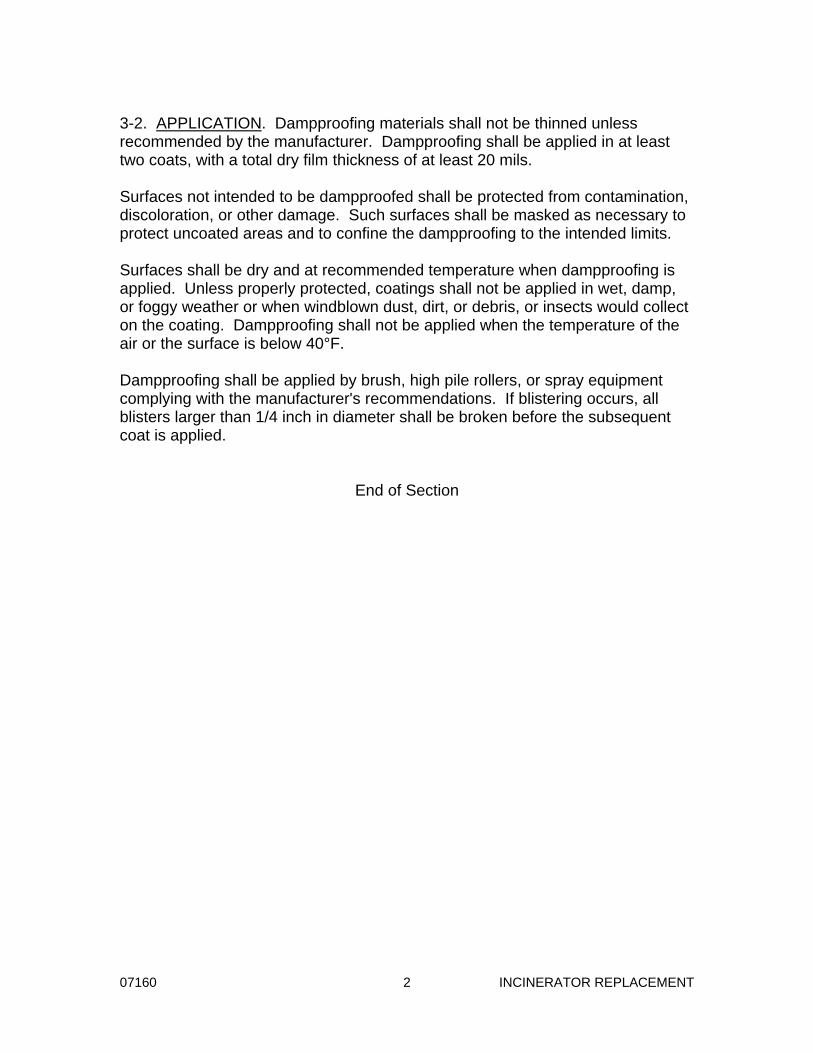
3-2. APPLICATION. Dampproofing materials shall not be thinned unless recommended by the manufacturer. Dampproofing shall be applied in at least two coats, with a total dry film thickness of at least 20 mils. Surfaces not intended to be dampproofed shall be protected from contamination, discoloration, or other damage. Such surfaces shall be masked as necessary to protect uncoated areas and to confine the dampproofing to the intended limits. Surfaces shall be dry and at recommended temperature when dampproofing is applied. Unless properly protected, coatings shall not be applied in wet, damp, or foggy weather or when windblown dust, dirt, or debris, or insects would collect on the coating. Dampproofing shall not be applied when the temperature of the air or the surface is below 40°F. Dampproofing shall be applied by brush, high pile rollers, or spray equipment complying with the manufacturer's recommendations. If blistering occurs, all blisters larger than 1/4 inch in diameter shall be broken before the subsequent coat is applied.
End of Section

07535 - 3 - INCINERATOR REPLACEMENT
PART 2 - PRODUCTS 2-1. MATERIALS. All materials used in construction of the roof membrane shall be furnished by the same manufacturer and shall conform to the following: Roofing System NRCA specification plate
MBA1-I-T-G2-M with base sheet. Base Sheet ASTM D4601, Type II fiberglass
reinforced base sheet. Intermediate Plies ASTM D2178, Type VI fiberglass
reinforced ply sheet. Cap Sheet Membrane Polyester reinforced, premium grade
APP modified bituminous cap sheet surfaced with mineral granules; Class A fire rating. Nominal 157 mils minimum, including mineral surface. Neutral or off-white, color selections will be required.
Flashing Sheets Asphalt impregnated glass fiber
sheet. Bituminous Materials Asphalt Primer ASTM D41. Mopping Asphalt First quality domestic grade, Type III,
ASTM D312 mopping grade. Vapor Retarder ASTM D4601, Type II fiberglass
reinforced base sheet. Insulation Polyisocyanurate foam faced both
sides with glass fiber felts; Fed Spec HH-I-1972/2, Class I; ASTM C1289; constant thickness and with factory tapered sections of 1/4 inch per foot to provide roof slopes as indicated on the drawings. Schuller tapered "UltraGard" or as recommended by the membrane manufacturer. Minimum thickness 3 ½ inches,
R Value – 21.1 per LTTR.

07535 - 4 - INCINERATOR REPLACEMENT
Cover Board ASTM C728, 1/2 inch expanded
perlite board; Schuller "Retro-Fit Board".
Cricket System Polyisocyanurate manufacturer's
standard cricket system. Preformed Cant Strips 4 inches by 4 inches. Roofing Nails 1-1/2 inch galvanized barbed type,
11 gage, with 7/16 inch dia heads. Sheet Metal Screws 1/4 - 14 x 1-1/2 HWH with sealing
washer, zinc plated. Masonry Nails Hardened-steel screw type, 9 gage,
with 5/16 inch dia heads. Mechanical Fasteners Factory Mutual approved for roof
insulation used. Unless otherwise specified, cap and counterflashings, sheet lead, pitch dams, and similar metal items are covered in Section 07600 – Sheet Metal. PART 3 - EXECUTION 3-1. PREPARATION OF ROOF SURFACES. New roof surfaces shall be cleaned and inspected before any roofing materials are applied. All drainage fix-tures shall be set at the proper level to permit free flow of water. The roof surfaces to be covered shall be smooth, hard, dry, and free from high spots and depressions, frost, or effects of frost. Roof surfaces shall be swept clean and free from dust, loosened cement scale, and debris. Roof surfaces shall be examined for openings, holes, or crevices which might allow bitumen to drip or flow through the deck or between the deck and vertical projections. Such openings shall be filled or covered before any roofing materials are applied.

08130 1 INCINERATOR REPLACEMENT
Section 08130
STEEL DOORS AND FRAMES
PART 1 - GENERAL 1-1. SCOPE. This section covers fire rated hollow metal doors and frames. Steel doors shall be flush type as indicated on the drawings. 1-2. GENERAL. Doors, frames, and appurtenances shall be furnished and installed as specified herein and in accordance with the details and arrangements indicated on the drawings. Doors shall be provided in the types and styles indicated on the drawings and specified herein. Fire doors and frames shall be provided at locations indicated. 1-2.01. Governing Standard. Except as modified or supplemented herein, all steel doors and frames shall conform to the requirements of ANSI/SDI 100. 1-2.02. Metal Gage. Gages of steel sheet metal specified herein refer to US Standard gage and are minimum permissible thicknesses. 1-2.03. Nomenclature. The nomenclature used herein conforms to ANSI A123.1. 1-3. SUBMITTALS. Complete detail drawings of all items specified herein shall be submitted in accordance with the submittals section. Drawings shall show elevations of each door type; details of each frame type; location or identification of each item; typical and special details of construction; methods of assembling sections; location and installation requirements for hardware; size, shape, and thickness of materials; joints; connections; and finish. 1-4. SHOP FINISH. A primer shall be applied to all surfaces of ferrous metal furnished under this section. Metal surfaces shall be cleaned and given a phosphate or equivalent treatment to ensure maximum corrosion protection and paint adherence. A dip or spray coat of synthetic resin, rust-inhibitive, metallic oxide or zinc chromate primer shall be applied to all surfaces, then baked or oven-dried. Finished surfaces shall be smooth and free from irregularities.

08130 2 INCINERATOR REPLACEMENT
PART 2 - PRODUCTS 2-1. ACCEPTABLE PRODUCTS. 2-1.01. Flush Type Doors. Subject to the requirements specified herein, flush type hollow metal doors shall be internally reinforced doors with accompanying frames equivalent to the following: The Ceco Corporation "Medallion" Curries Manufacturing Company "Series 747T" Pioneer Industries "Series C" Republic Builders Products "DS Series" 2-1.02. Fire Doors. Subject to the requirements specified herein, fire doors and frames listed on the drawings to be Class A or Class B shall be equivalent to the following: The Ceco Corporation "Fuego" Curries Manufacturing Company "727" Pioneer Industries "Series C" Republic Builders Products "DE Series" 2-2. MATERIALS. Materials used in the manufacture and installation of steel doors and frames shall be as follows: Doors and Frames ASTM A366 or A569, stretcher leveled,
commercial quality sheet steel with smooth, clean surface.
Internal Reinforcing ASTM A366, cold-rolled steel. Fillers for Internally Mineral wool or fiberglass. Reinforced Doors Anchoring Devices Zinc plated where exposed; zinc plated
or galvanized where concealed. Expansion Anchors As specified in the anchor bolts and
expansion anchors section. Tape Sealant PVC or neoprene closed-cell foam,
black, 1/2 inch wide by 1/4 inch thick strip with pressure-sensitive adhesive back; Williams "Everlastic NN-1" or Blanchard "Foamgard".

08130 3 INCINERATOR REPLACEMENT
2-3. FRAMES. Frames for doors, transoms, sidelights, mullions, and interior glazed panels shall be formed of steel to the sizes and shapes indicated. Metal for frames shall be not lighter than 14 gage. 2-3.01. Workmanship. The finished work shall be strong and rigid, neat in appearance, and free from defects. Molded members shall be fabricated straight and true with corner joints well formed, and with fastenings concealed where practicable. 2-3.02. Joints. Joints for frames shall be mitered or butted and continuously welded on the reverse side to produce rigid joints which are invisible on the face of the frame. Frame bottoms shall be held rigidly in position by spreader bars to maintain proper alignment during shipment and erection. 2-3.03. Hardware Provisions. Frames shall be prepared at the factory for the specified hardware. Frames shall be mortised, reinforced, drilled, and tapped for mortised hardware, and shall be reinforced for surface-applied hardware. Cover boxes shall be provided in back of all hardware cutouts. Frames for all doors except weatherstripped doors shall be punched to receive silencers, three holes on the lock side of single door frames and one hole for each leaf in heads of double door frames. Lock strikes shall be set out and adjusted to provide clearance for silencers. Concealed metal reinforcements shall be provided for hardware with the following minimum thicknesses: Hinge reinforcement 10 gage Strike reinforcement 14 gage Closer reinforcement 12 gage Other reinforcement 14 gage 2-3.04. Mullions and Transom Bars. Mullions and transom bars shall be reinforced tubular construction connecting neatly with heads and jambs and secured in place by concealed interlocking joints or by welding. Mullions and transoms shall be as indicated on drawings. 2-3.05. Wall and Floor Anchors. Metal anchors of the sizes and shapes required for the adjoining type of wall construction shall be provided. Jamb anchors shall be fabricated from steel, with thickness not less than the gage used for frames. Anchors shall be located near the top and bottom of each frame and at intermediate points not to exceed 32 inches spacing. For frames set in masonry, jamb anchors shall be at least 10 inches long, adjustable, and corrugated or other deformed type.

08130 4 INCINERATOR REPLACEMENT
For frames set in metal stud partitions, anchors shall be welded to the backs of frames. Anchors shall be fastened to steel studs with 1/4 inch diameter machine bolts, or by welding. For frames set in hardened concrete, anchorage shall be provided as indicated on the drawings. Door frames shall be anchored to the floor with a 16 gage base clip at each jamb. Clips shall be sized and drilled for at least two 3/8 inch diameter anchoring devices. 2-3.06. Stops and Beads. Metal glazing beads shall be furnished with hollow metal frames at transoms, sidelights, interior glazed panels, and other locations where glazed frames are indicated on the drawings. Glazing stops shall be formed as an integral part of the frames, and the frames shall be prepared to receive the glazing beads. Where frames are exposed to weather, the integral stops shall be located on the exterior side of the frames. Beads shall be fastened to frames with oval head machine screws spaced at 9 inch centers maximum. Beads having a molded shape shall be mitered at corners. Rectangular beads may be either mitered or butted at corners. 2-4. DOORS. Doors indicated on the drawings as hollow metal shall be flush type as specified herein. Doors shall be prepared to receive the hardware specified in the finish hardware section. 2-4.01. Workmanship. Doors shall be rigid, neat in appearance, and free from defects. Molded members for glazed doors shall be formed straight and true, with joints coped or mitered, well formed, and in true alignment. All welded joints on exposed surfaces shall be dressed smooth so that they are invisible after finishing. 2-4.02. Sizes and Clearances. Doors shall be 1-3/4 inches thick, seamless type, of the sizes and designs indicated. Clearances for doors, except fire doors, shall be 1/8 inch at jambs and heads, 1/4 inch at meeting stiles of pairs of doors, and 3/4 inch at bottom unless otherwise indicated or specified. Clearances for fire doors shall be as required by NFPA Pamphlet No. 80 or by the authority having jurisdiction. 2-4.03. Construction. Doors shall have 18 gage seamless outer sheets. Side edges of doors shall be flush and closed watertight. All seams shall be continuously welded and ground smooth. Doors shall be prepared at the factory for hardware and for glazing as indicated on the drawings and as specified. Door edges shall be beveled or rounded.
08130 5 INCINERATOR REPLACEMENT
Internally reinforced doors shall have fillers placed in the spaces between reinforcing members and shall be reinforced by 22 gage or heavier vertical steel stiffeners installed on 6 inch centers and welded to face sheets. Outswinging exterior doors shall be finished flush at the top, with all seams and joints closed watertight as specified for side edges. 2-4.04. Fire Doors. Fire doors and frames shall be constructed and installed in accordance with the requirements of, and shall bear the label of, Underwriters' Laboratories for the class of opening and rating indicated on the drawings, or corresponding classification by Factory Mutual. For doors exceeding the Underwriters' Laboratories size limitations for labeling, the UL "Certificate for Oversize Construction" shall be provided. Authorized construction details and requirements for labeling shall take precedence over these specifications, except when thicker gages of metal are required by these specifications. 2-4.05. Hardware Provisions. Doors shall be mortised, reinforced, drilled, and tapped for mortised hardware. Reinforcing units shall be provided for locksets. Reinforcing plates shall be provided for mortised and surface-applied hardware in at least the following thicknesses: Hinge reinforcement 10 gage Surface-applied closers 12 gage and hold-open arms Other reinforcement 14 gage The locations of hardware items shall be in accordance with DHI "Recommended Locations for Builders' Hardware for Standard Steel Doors and Frames". 2-4.06. Stops and Beads. Metal glazing beads shall be furnished with hollow metal doors where glazed doors are indicated on the drawings. Glazing stops may be formed as an integral part of the doors, or separate glazing beads provided for both sides of the glass. Doors shall be prepared to receive the glazing beads. Beads shall be snapped into place, or shall be fastened with oval head machine screws spaced at 9 inch centers maximum. Beads having a molded shape shall be mitered at corners. Rectangular beads may be either mitered or butted at corners. Where doors are exposed to weather, all seams and joints on all sides of the glass panel, except joints in removable beads, shall be closed watertight as specified for side edges. 2-4.07. Astragals. The meeting edges of all exterior double doors shall be provided with astragals. Fire doors shall be equipped with solid, bar type astragals. Astragals shall be applied to the active leaf unless otherwise indicated.

08130 6 INCINERATOR REPLACEMENT
PART 3 - EXECUTION 3-1. Installation. Frames shall be set in position, plumbed, aligned, and braced securely until permanent anchors are set. Frames shall be anchored to floors with expansion anchors or as indicated on the drawings. Jamb anchors shall be built into walls and secured to adjoining construction. Spreader bars shall remain in place until frames have been built into the walls. End of Section

11920 – Subcontractor Contract Bond -1- INCINERATOR REPLACEMENT
SUBCONTRACTOR CONTRACT BOND (As provided for in SECTION 153.571 ORC)
KNOW ALL MEN BY THESE PRESENTS: That we, the undersigned, , as principal, (Business Name & Address) and , as sureties, (Surety Name & Address) licensed to do business in the State of Ohio, are held and firmly bound unto , hereinafter called the Obligee, in (General Contractor Name) the penal sum of $20,000,000 (twenty million dollars), to undertake the supply of Specification Section 11920 items for:
PROPOSED SANITARY SEWER NO. 5565P2, CIP No. 2004-10, MILL CREEK WASTEWATER TREATMENT PLANT INCINERATOR REPLACEMENT, PHASE 2
The penal sum referred to herein shall be the dollar amount of the principal’s subcontract to the Obligee, incorporating any additive or deductive alternative proposals made by the principal to the Obligee, which are accepted by the Obligee. In no case shall the penal sum exceed the sum of $20,000,000 (twenty million dollars). For payment of the penal sum well and truly to be made, we hereby jointly and severally bind ourselves, our heirs, executors, administrators, successors, and assigns. NOW, THEREFORE, if the said as principal, (Business Name & Address) shall well and faithfully do and perform each and every condition of such contract; and indemnify the Obligee against all damage suffered by failure to perform such contract according to the provisions thereof and in accordance with the plans, details, specifications, and bills of material therefore; and shall pay all lawful claims of subcontractors, materialmen, and laborers, for labor performed and materials furnished in the carrying forward, performing, or completing of said contract (including 1 year guarantee period); we agreeing and assenting that this undertaking shall be for the benefit of any materialmen or laborer having a just claim, as well as for the Obligee herein; then this obligation shall be void; otherwise the same shall remain in full force and effect; it being expressly understood and agreed that the liability of the surety for any and all claims hereunder shall in no event exceed the penal amount of this obligation as herein stated. The said surety stipulates and agrees that no modifications, omissions or additions, in or to the terms of said contract or in or to the plans or specifications thereof shall in any wise affect the obligation of said surety on its bond. SIGNED this ___________ day of _________________________________, 20____.

11920 – Subcontractor Contract Bond -2- INCINERATOR REPLACEMENT
Name, as Principal
Subcontractor Representative’s Signature
Subcontractor Representative’s Printed Name & Title
Surety Name
Surety Agent’s Signature & Printed Name
Surety Address
Surety E-mail Address APPROVED AS TO FORM AND SUFFICIENCY OF SURETY: Subcontractor Surety’s Agent (NOTE TO SURETY: THIS BOND MUST HAVE PROPER POWER OF ATTORNEY ATTACHED AFTER THIS PAGE)