The Metrolink Finback Bridge, Manchester - ABECE · The Metrolink Finback Bridge, Manchester S.W...
6
Tailor Made Concrete Structures – Walraven & Stoelhorst (eds) © 2008Taylor & Francis Group, London, ISBN 978-0-415-47535-8 The Metrolink Finback Bridge, Manchester S.W. Jones Gifford, Chester, UK R.G. Wrigley Gifford, Southampton, UK ABSTRACT: The Manchester to Oldham Line of the proposed Metrolink Phase 3 tram system passes through the new Central Park Business Park utilising the existing track bed of a disused and dismantled heavy rail route. To the west of Thorp Road Bridge the new Metrolink route crosses the existing four tracks of the Manchester to Leeds Trans-Pennine railway. A post-tensioned concrete finback bridge has been provided to carry the new twin Metrolink tracks over the existing heavy rail route. In order to minimise disruption to the operational railway, the Finback Bridge was constructed in a position alongside to and roughly parallel to the existing railway. Once the construction was substantially complete, the 6,250 tonne bridge was rotated in plan through 21 ◦ to its final position during a weekend possession. 1 INTRODUCTION In the Moston area of northeast Manchester, the route of the proposed Phase 3 of the Manchester Metrolink tram system crosses the four tracks of the Trans- Pennine Manchester to Leeds. The original heavy rail configuration had two lines merging utilising level points; however the safety requirement was for the new Metrolink tram line to be grade separated from the existing operational heavy railway. Initial designs for crossing the railway considered both tunnelling below the operational railway with a series of jacked box structures and alternatively pro- viding a new bridge to carry the tramline over the heavy rail lines. The tunnelling option was not preferred because of the disruption it would cause to the oper- ational railway and the extensive modifications that would be required to the adjacent Thorp Road Bridge. The option selected was a two span post-tensioned prestressed concrete box-girder finback design. The Finback Bridge was designed and constructed as part of an enabling contract to create a new entrance into the Central Park Business Park being created on the 200 hectare site of the former Monsall Hospital. This project also involved the design and construction of the structures required for a new Metrolink stop for the new business park along with the crossing of the heavy rail lines. The ground conditions consist of 1.5 m of Made Ground comprising 300 mm of ballast, overlying vary- ing thicknesses of medium gravel, cobbles, gravely sand and soft to firm gravely clay. Directly underlying the Made Ground is Glacial Till to a depth of approx- imately 33 m below existing ground level. 2 CONCEPTUAL DESIGN The form of the Finback Bridge developed in response to the many constraints of the site. The vertical alignment of the tram lines carried by the bridge had to have vertical gradients no greater than 5.5%, and when combined with the horizontal alignment had to allow theoretical tram transit times between the new Central Park stop and the subsequent Dean Lane stop of less than 96 seconds. The bridge had to provide a minimum headroom over the existing heavy rail lines of 4.80 m. Therefore the vertical align- ment had to rise to clear the railway and then drop to pass through the southwest span of the existing Thorp Road Bridge to achieve a headroom of 4.35 m to the soffit. The close proximity to the operational railway also meant there were significant constraints for construc- tion clearances. A lateral clearance of 3.0 m was adopted for construction and the central pier position was required to be more than 4.5 m from the nearest rail to be outside the zone of train impact. To satisfy all these constraints the resulting align- ment of the bridge is a compound ‘S’ shaped curve in plan (Fig. 1). A consequence of the curved horizon- tal alignment is that significant torsions are induced within the deck from both permanent and transient loading. 857
Transcript of The Metrolink Finback Bridge, Manchester - ABECE · The Metrolink Finback Bridge, Manchester S.W...

Tailor Made Concrete Structures – Walraven & Stoelhorst (eds)© 2008 Taylor & Francis Group, London, ISBN 978-0-415-47535-8
The Metrolink Finback Bridge, Manchester
S.W. JonesGifford, Chester, UK
R.G. WrigleyGifford, Southampton, UK
ABSTRACT: The Manchester to Oldham Line of the proposed Metrolink Phase 3 tram system passes throughthe new Central Park Business Park utilising the existing track bed of a disused and dismantled heavy rail route.To the west of Thorp Road Bridge the new Metrolink route crosses the existing four tracks of the Manchester toLeeds Trans-Pennine railway. A post-tensioned concrete finback bridge has been provided to carry the new twinMetrolink tracks over the existing heavy rail route. In order to minimise disruption to the operational railway,the Finback Bridge was constructed in a position alongside to and roughly parallel to the existing railway. Oncethe construction was substantially complete, the 6,250 tonne bridge was rotated in plan through 21◦ to its finalposition during a weekend possession.
1 INTRODUCTION
In the Moston area of northeast Manchester, the routeof the proposed Phase 3 of the Manchester Metrolinktram system crosses the four tracks of the Trans-Pennine Manchester to Leeds. The original heavy railconfiguration had two lines merging utilising levelpoints; however the safety requirement was for thenew Metrolink tram line to be grade separated fromthe existing operational heavy railway.
Initial designs for crossing the railway consideredboth tunnelling below the operational railway with aseries of jacked box structures and alternatively pro-viding a new bridge to carry the tramline over the heavyrail lines. The tunnelling option was not preferredbecause of the disruption it would cause to the oper-ational railway and the extensive modifications thatwould be required to the adjacent Thorp Road Bridge.The option selected was a two span post-tensionedprestressed concrete box-girder finback design.
The Finback Bridge was designed and constructedas part of an enabling contract to create a new entranceinto the Central Park Business Park being created onthe 200 hectare site of the former Monsall Hospital.This project also involved the design and constructionof the structures required for a new Metrolink stop forthe new business park along with the crossing of theheavy rail lines.
The ground conditions consist of 1.5 m of MadeGround comprising 300 mm of ballast, overlying vary-ing thicknesses of medium gravel, cobbles, gravelysand and soft to firm gravely clay. Directly underlying
the Made Ground is Glacial Till to a depth of approx-imately 33 m below existing ground level.
2 CONCEPTUAL DESIGN
The form of the Finback Bridge developed in responseto the many constraints of the site.
The vertical alignment of the tram lines carried bythe bridge had to have vertical gradients no greaterthan 5.5%, and when combined with the horizontalalignment had to allow theoretical tram transit timesbetween the new Central Park stop and the subsequentDean Lane stop of less than 96 seconds. The bridgehad to provide a minimum headroom over the existingheavy rail lines of 4.80 m. Therefore the vertical align-ment had to rise to clear the railway and then drop topass through the southwest span of the existing ThorpRoad Bridge to achieve a headroom of 4.35 m to thesoffit.
The close proximity to the operational railway alsomeant there were significant constraints for construc-tion clearances. A lateral clearance of 3.0 m wasadopted for construction and the central pier positionwas required to be more than 4.5 m from the nearestrail to be outside the zone of train impact.
To satisfy all these constraints the resulting align-ment of the bridge is a compound ‘S’ shaped curve inplan (Fig. 1). A consequence of the curved horizon-tal alignment is that significant torsions are inducedwithin the deck from both permanent and transientloading.
857
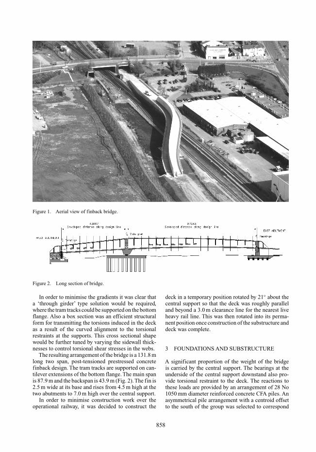
Figure 1. Aerial view of finback bridge.
Figure 2. Long section of bridge.
In order to minimise the gradients it was clear thata ‘through girder’ type solution would be required,where the tram tracks could be supported on the bottomflange. Also a box section was an efficient structuralform for transmitting the torsions induced in the deckas a result of the curved alignment to the torsionalrestraints at the supports. This cross sectional shapewould be further tuned by varying the sidewall thick-nesses to control torsional shear stresses in the webs.
The resulting arrangement of the bridge is a 131.8 mlong two span, post-tensioned prestressed concretefinback design. The tram tracks are supported on can-tilever extensions of the bottom flange. The main spanis 87.9 m and the backspan is 43.9 m (Fig. 2).The fin is2.5 m wide at its base and rises from 4.5 m high at thetwo abutments to 7.0 m high over the central support.
In order to minimise construction work over theoperational railway, it was decided to construct the
deck in a temporary position rotated by 21◦ about thecentral support so that the deck was roughly paralleland beyond a 3.0 m clearance line for the nearest liveheavy rail line. This was then rotated into its perma-nent position once construction of the substructure anddeck was complete.
3 FOUNDATIONS AND SUBSTRUCTURE
A significant proportion of the weight of the bridgeis carried by the central support. The bearings at theunderside of the central support downstand also pro-vide torsional restraint to the deck. The reactions tothese loads are provided by an arrangement of 28 No1050 mm diameter reinforced concrete CFA piles. Anasymmetrical pile arrangement with a centroid offsetto the south of the group was selected to correspond
858

Figure 3. Cross-section of deck.
to the centroid of the imposed permanent loading.The pile group is connected by a stepped reinforcedconcrete pilecap to minimise excavation depths adja-cent to the railway. These piles are founded in theGlacial Till.
The east abutment is also supported on a group of 10No 1050 mm diameter reinforced concrete CFA piles.The bearings on this abutment are offset to the southprimarily to provide clearance to the adjacent railwaybut also to correspond to the centroid of the verticalloads and offer torsional restraint.
The short backspan induces uplift reactions at thewest abutment. Therefore the west abutment is a padfoundation with an arrangement of two bearings andfour short near-vertical post-tensioning tendons toresist uplift.
4 SUPERSTRUCTURE
4.1 Description of structural form
A typical cross section of the superstructure is indi-cated in Fig. 3. The superstructure has constant exter-nal dimensions with horizontal cantilever slabs andis ‘extruded’ along the design alignment with somevariations. The height of the fin varies, being a maxi-mum over the intermediate support and the internaldimensions of the fin vary to allow thickening ofwebs, base slab and roof. The external width of thefin was minimised within the requirements for accessand structural adequacy. The transverse slab thick-ness was minimised to mitigate the headroom andassociated track gradients. Track cant is provided byvarying height rail plinths; detailed geometric checksbeing made to ensure that clearances to the fin weremaintained. Subsequent checks on the deflected shapeconfirmed that the track cant in service remains withinacceptable tolerances.
Distortion of the fin is controlled by internaldiaphragms, which are also used to provide anchoragesfor the external tendons.
The superstructure is post-tensioned longitudinallywith external tendons, within the fin, over the interme-diate support and internal grouted tendons in the slabof the main span. Transversely the cantilever wings ofthe deck act as normally reinforced concrete members.
4.2 Design loading and thermal stressdistributions
In general, design loading is in accordance with BS5400 Part 2, but with additional interpretation appliedto better suit the structural configuration and methodof analysis. The bridge is intended to carry a light tramsystem, however is designed for standard RL railwayloading.
The ultimate limit state load factors given in BS5400 Part 4, Clause 4.2.2 for creep and shrinkage arenot appropriate to an analysis that explicitly incorpo-rates time dependent effects and instead global loadfactors to be applied to the SLS time dependent results(of 1.2 and 1.1 for γfl and γf3, respectively) were agreedwith the Client.
SLS stress and crack width limitations were basedon BS 5400 Part 4 Clause 4.2.2 (a). The applicationof the requirements to a post-tensioned railway struc-ture with a mixed tendon arrangement is not fullydefined and it was agreed with the Client that in ten-sile zones containing only internal grouted tendons,the structure would be checked for Class 1 stressesunder permanent loads only and Class 3 stresses witha 0.25 mm crack width, for all other combinations. Intensile zones containing external tendons, the structurewould be checked for Class 1 stresses under permanentloads only and as a reinforced concrete section for allother combinations.
More appropriate differential temperature profileswere agreed with the Client based on winter andsummer sun, positive and negative difference and theorientation of the structure.
4.3 Method of analysis
Analysis of the superstructure was carried out in twostages.
Preliminary design, section sizing and post-tensioning requirements were determined using a‘line beam’ and the computer package Sofistik, a 3Dtime dependent analysis program.The simplicity of theline beam model and the use of a simplified construc-tion sequence enabled the various design parameters tobe optimised fairly rapidly, and, as it transpired, fairlyaccurately. During this preliminary work it becameclear that the overriding design effect was to be the webshear stresses under the worst combination of verticalshear and torsion and at this stage various mitigatingmeasures were considered such as an internal compos-ite steel lining. It was determined, however, to retain
859
the simplicity of the concrete structure and althoughdepartures for the use of higher strength concretes wereagreed with the Client, these were not, in the finalevent, implemented. This preliminary work was car-ried out by Bilfinger Berger and enabled an early startto be made on the design of the temporary works.
The final design was carried out using a 3D shellelement model of the full superstructure. This enabledsection sizes and post-tensioning requirements to beoptimised and included full time dependent effectsbased on the proposed construction programme. Allconstruction stages were modelled, including rigidbody movements, enabling falsework loads and tem-porary works effects to be investigated. Some reduc-tions were made in the numbers of external tendons butmore significantly in those in the slab. Fin web thick-nesses were finalised on the basis of limiting combinedshear stresses with the discreet loading from the exter-nal tendon anchorages being incorporated. Transversereinforcement requirements were determined directlyfrom the model and the facility of the Sofistik soft-ware to section the model to report stress summariesenabled the ultimate strength to be checked.
4.4 Post-tensioning systems
The post-tensioning system was based on theFreyssinet range and early discussions with Freyssinetenabled both the physical properties and design param-eters to be incorporated into the design process at anearly stage.
External tendons in the fin are all Freyssinet Sys-tem 2, 37R15, and a total of eighteen are used. TheType 2 system comprises discreet greased and sheathedstrands in an HDPE duct, which is cementitiouslygrouted prior to stressing.The protection system is pro-vided by the greased sheath and the duct.The grout is aspacing mechanism to enable individual strands to bereplaced, should the need arise, in the future. In gen-eral, due to the limited access, stressing was carriedout using a mono jack from one end although jackinganchorages were provided at both ends.
Grouted tendons in the slab are all Freyssinet Sys-tem 1, 37C15, and a total of six are used. The Type 1system comprises conventional bare strands in a cor-rugated plastic duct, cast into the concrete, which iscementitiously grouted after stressing. The protectionsystem is provided by the grout and the duct. Stressingwas carried out using a conventional multistrand jackfrom the intermediate support anchorages althoughjacking anchorages were provided at both ends.
The vertical stressing at the west abutment com-prises four slightly inclined ungrouted tendons. Eachtendon contains 19C15-galvanised strands within gal-vanised steel formwork tubes. The corrosion protec-tion at the gap between the deck and the substructureis a flexible plastic gaiter.
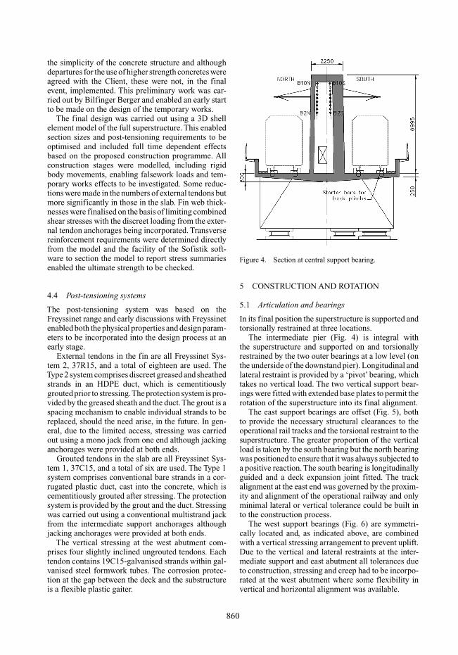
Figure 4. Section at central support bearing.
5 CONSTRUCTION AND ROTATION
5.1 Articulation and bearings
In its final position the superstructure is supported andtorsionally restrained at three locations.
The intermediate pier (Fig. 4) is integral withthe superstructure and supported on and torsionallyrestrained by the two outer bearings at a low level (onthe underside of the downstand pier). Longitudinal andlateral restraint is provided by a ‘pivot’ bearing, whichtakes no vertical load. The two vertical support bear-ings were fitted with extended base plates to permit therotation of the superstructure into its final alignment.
The east support bearings are offset (Fig. 5), bothto provide the necessary structural clearances to theoperational rail tracks and the torsional restraint to thesuperstructure. The greater proportion of the verticalload is taken by the south bearing but the north bearingwas positioned to ensure that it was always subjected toa positive reaction. The south bearing is longitudinallyguided and a deck expansion joint fitted. The trackalignment at the east end was governed by the proxim-ity and alignment of the operational railway and onlyminimal lateral or vertical tolerance could be built into the construction process.
The west support bearings (Fig. 6) are symmetri-cally located and, as indicated above, are combinedwith a vertical stressing arrangement to prevent uplift.Due to the vertical and lateral restraints at the inter-mediate support and east abutment all tolerances dueto construction, stressing and creep had to be incorpo-rated at the west abutment where some flexibility invertical and horizontal alignment was available.
860

Figure 5. Section at east abutment.
Figure 6. Section at east abutment.
5.2 Construction position and sequence
The limitations on clearances, as indicated above, tothe operational railway and the required final align-ment of the bridge resulted in the centre of rotationof the structure being offset from the actual struc-ture centreline (Fig. 7). The geometric definition ofthe superstructure falsework (in the construction posi-tion) was based on the final design line alignment afterapplying a transposition matrix for an anti-clockwise
Figure 7. Plan rotation of deck.
rotation of 21◦ to give xyz coordinates at any lateraloffset from the design line.
Consideration was given to pre-cambering the caststructure both for vertical deflection, plan deflec-tion and torsion. The analysis suggested that whenresting on its bearings under permanent loads the ver-tical alignment would be fairly neutral, both in theshort and long terms, and precamber would not beneeded. Due to the post-tensioning being applied to acurved-in-plan structure the plan shape changes dur-ing stressing.The plan deflection is significant, 50 mmat the west end, the east being fixed, but this couldbe accommodated by measures incorporated into thewest abutment construction and proposed track align-ment. No plan precamber was proposed. The verticaldeflections due to torsions in service were significantbut due to the shape of the soffit did not compromiseheadroom. The variation in cant was within accept-able limits and consequently no torsional precamberwas proposed. The lack of need for any casting pre-camber greatly simplified the definition of the castgeometry.
The construction sequence was modelled in somedetail with a view to:
• Ensuring that the structure was not overstressed, intension or compression, or under strength at anytime during the construction process.
861

Figure 8. Temporary steel fabrication to support end of mainspan during rotation.
• Ensuring that the loading on the falsework, andother temporary works, did not exceed the designmagnitudes.
• Ensuring that the deflected shape at the time of rota-tion could be accommodated by substructure andbearing levels.
In view of the fact that the shape of the structure isboth load and time dependant, the analysis was con-tinuously re-run during the construction process usingreal times and actual jack loads in order to ensure theintegrity of the structure at all times and to adviseof any minor adjustments to enable construction toproceed as smoothly as possible.
5.3 Temporary works
Prior to and during rotation, the superstructure wassupported on the intermediate pier bearings and atemporary nose at the east end, bearing on a slidingtrack over the operational railway. The backspan wasin cantilever.The temporary nose was a structural steelfabrication (Fig. 8) fixed to the east bearing downstandand the fin webs with a push pull system of cast-inanchors. The bearing downstand required a substan-tial steel member to be cast-in in order to adequatelytransfer the loads from the fin webs into the steel nos-ing. The sliding end of the nose was offset from thedeck end in order to provide adequate clearance to thepermanent works and offset from the bridge centrelinein order to minimise torsional rotations whilst on thesingle bearing.
The nosing was supported on a sliding trackfounded on a temporary reinforced concrete wallinside the construction limits and on a temporary steelbeam over the operational railway. The beam was bothplaced and removed during the same track possessionused for the rotation.
Figure 9. Temporary PTFE sliding track and jack.
5.4 Rotation
The rotation into the final position was carried outduring a track possession and achieved by pushing thenose on a PTFE sliding track using a system of jackson a rack (Fig. 9).
6 CONCLUSIONS
This paper describes the design and construction of anunusual railway bridge structure in Manchester. TheFinback Bridge carries the proposed Metrolink Phase 3over existing heavy rail tracks.A novel design compris-ing a varying height finback form of construction hasbeen developed. The central torsion box has varyingwall thickness to control torsional shear stresses.Threetypes of post-tensioning are used in the design. Thedesign provides an efficient and cost effective struc-tural solution. Easy access to the main post-tensioningtendons, for inspection and maintenance, is providedfrom within the void in the fin.
An innovative method of construction has beenadopted to minimise the disruption of the adjacentoperational railway. The bridge superstructure wasconstructed in a temporary position roughly parallelto the railway. The substructure was rotated in planthrough 21◦ to its service position during a weekendpossession of railway. This proved to be a successfuland cost effective construction method that minimiseddisruption to the operational railway below.
REFERENCES
British Standards Institution. 2006. Steel, Concrete and Com-posite Bridges. BS5400 Part 2 – Specification for loads.BSI, Milton Keynes.
British Standards Institution. 1990. Steel, Concrete and Com-posite Bridges. BS 5400 Part 4 – Code of Practice forDesign of Concrete Bridges. BSI, Milton Keynes.
862