The mesh disturbance effects in a low-temperature cascade arc torch for surface modification of low...
13
The Mesh Disturbance Effects in a Low-Temperature Cascade Arc Torch for Surface Modification of Low Density Polyethylene Mary Gilliam, Andrew Ritts, Qingsong Yu Center for Surface Science and Plasma Technology, Department of Mechanical and Aerospace Engineering, University of Missouri-Columbia, Columbia, Missouri 65211 Received 22 December 2008; accepted 30 January 2010 DOI 10.1002/app.32239 Published online 26 May 2010 in Wiley InterScience (www.interscience.wiley.com). ABSTRACT: A stainless steel mesh was placed in a low- temperature cascade arc torch (LTCAT) to study its dis- turbance effects on the plasmas and on the surface modifi- cation of low density polyethylene (LDPE). It was found that the photoemitting species were deflected by the screen and only faint glow was observed after the mesh. Optical emission spectroscopy examination indicated that the amount of electronically excited species in the plasma was greatly reduced after passing through the mesh. Grounding the mesh altered the nature of the discharge and a greater intensity of O emission was observed in Ar LTCAT þ O 2 discharge, which indicated greater energy transfer to the oxygen. Although a decrease in surface damage was observed on the treated LDPE samples by placement of the mesh in the Ar LTCAT discharges, the wettability achieved was also greatly reduced. V C 2010 Wiley Periodicals, Inc. J Appl Polym Sci 118: 805–817, 2010 Key words: polyethylene; cascade arc torch; plasma treatment; mesh disturbance; surface modification; contact angle INTRODUCTION Surface modification treatments are often applied to polymeric surfaces for the enhancement of adhesion, wettability, biocompatibility, printability, barrier properties, susceptibility to harsh agents, and other interfacial characteristics. 1–6 Surface modification treatments can involve deposition of thin films or chemical changes in the top molecular layers. Among the surface modification treatments applied to polymers, plasma processes, including low-pres- sure plasma, present advantages over other treat- ments, such as wet chemical treatments and mechan- ical roughening. Plasma processes are versatile and environmentally benign methods for polymeric sur- face modification. 5 Plasma treatments of polymers that involve chemi- cal surface modification can induce surface function- alization, in which new surface functional groups are created, surface crosslinking, and degradation. Plasma processes can have significant drawbacks for polymer surface treatment, though, due to the diffi- culties in optimization of certain desirable reactions and in minimization of undesired consequences, such as surface degradation. 7 Many species exist in low-pressure plasmas, including high-energy ions, electrons, vacuum ultraviolet (VUV) and ultraviolet (UV) photons, excited neutral species, reactive free radicals, and neutrals. Bombardment from high- energy species, such as ions, can result in significant ablation of surface moieties, chain scission, and sur- face degradation. 8–10 Degradation can occur in the form of etching into volatile species, which could be desirable or tunable to fit the application, or the scis- sion of surface macromolecular chains into oligom- ers or low molecular weight oxidized materials (LMWOM), which form a weak boundary layer on the surface that is detrimental to adhesion and stability. Recent studies 1,11 have demonstrated many unique advantages of low-temperature cascade arc torch (LTCAT) over traditional plasma techniques, including significant reduction of degradation on polymer surfaces and enhanced surface stability. In addition, LTCAT treatment is fast and effective, in the case of Ar LTCAT, 2 s exposure time was reported to be sufficient for the surface modification of low density polyethylene (LDPE), which was much faster than the 120 s that was required for Ar RF plasma treatment. 1 LTCAT consists of a beam of mainly excited neutral species of a noble gas, whereas most of the ions and electrons are contained in a DC arc generator. 12,13 However, some ions and low energy electrons (0.3–1.5 eV) 14 escape the dis- charge generator and remain in the beam that Correspondence to: Q. Yu ([email protected]). Contract grant sponsors: Research Council Grant and Faculty Start-up Fund of College of Engineering, University of Missouri-Columbia. Journal of Applied Polymer Science, Vol. 118, 805–817 (2010) V C 2010 Wiley Periodicals, Inc.
-
Upload
mary-gilliam -
Category
Documents
-
view
216 -
download
2
Transcript of The mesh disturbance effects in a low-temperature cascade arc torch for surface modification of low...

The Mesh Disturbance Effects in a Low-TemperatureCascade Arc Torch for Surface Modification ofLow Density Polyethylene
Mary Gilliam, Andrew Ritts, Qingsong Yu
Center for Surface Science and Plasma Technology, Department of Mechanical and Aerospace Engineering,University of Missouri-Columbia, Columbia, Missouri 65211
Received 22 December 2008; accepted 30 January 2010DOI 10.1002/app.32239Published online 26 May 2010 in Wiley InterScience (www.interscience.wiley.com).
ABSTRACT: A stainless steel mesh was placed in a low-temperature cascade arc torch (LTCAT) to study its dis-turbance effects on the plasmas and on the surface modifi-cation of low density polyethylene (LDPE). It was foundthat the photoemitting species were deflected by thescreen and only faint glow was observed after the mesh.Optical emission spectroscopy examination indicated thatthe amount of electronically excited species in the plasmawas greatly reduced after passing through the mesh.Grounding the mesh altered the nature of the discharge
and a greater intensity of O emission was observed in ArLTCAT þ O2 discharge, which indicated greater energytransfer to the oxygen. Although a decrease in surfacedamage was observed on the treated LDPE samples byplacement of the mesh in the Ar LTCAT discharges, thewettability achieved was also greatly reduced. VC 2010 WileyPeriodicals, Inc. J Appl Polym Sci 118: 805–817, 2010
Key words: polyethylene; cascade arc torch; plasma treatment;mesh disturbance; surface modification; contact angle
INTRODUCTION
Surface modification treatments are often applied topolymeric surfaces for the enhancement of adhesion,wettability, biocompatibility, printability, barrierproperties, susceptibility to harsh agents, and otherinterfacial characteristics.1–6 Surface modificationtreatments can involve deposition of thin films orchemical changes in the top molecular layers.Among the surface modification treatments appliedto polymers, plasma processes, including low-pres-sure plasma, present advantages over other treat-ments, such as wet chemical treatments and mechan-ical roughening. Plasma processes are versatile andenvironmentally benign methods for polymeric sur-face modification.5
Plasma treatments of polymers that involve chemi-cal surface modification can induce surface function-alization, in which new surface functional groupsare created, surface crosslinking, and degradation.Plasma processes can have significant drawbacks forpolymer surface treatment, though, due to the diffi-culties in optimization of certain desirable reactionsand in minimization of undesired consequences,
such as surface degradation.7 Many species exist inlow-pressure plasmas, including high-energy ions,electrons, vacuum ultraviolet (VUV) and ultraviolet(UV) photons, excited neutral species, reactive freeradicals, and neutrals. Bombardment from high-energy species, such as ions, can result in significantablation of surface moieties, chain scission, and sur-face degradation.8–10 Degradation can occur in theform of etching into volatile species, which could bedesirable or tunable to fit the application, or the scis-sion of surface macromolecular chains into oligom-ers or low molecular weight oxidized materials(LMWOM), which form a weak boundary layer onthe surface that is detrimental to adhesion andstability.Recent studies1,11 have demonstrated many
unique advantages of low-temperature cascade arctorch (LTCAT) over traditional plasma techniques,including significant reduction of degradation onpolymer surfaces and enhanced surface stability. Inaddition, LTCAT treatment is fast and effective, inthe case of Ar LTCAT, 2 s exposure time wasreported to be sufficient for the surface modificationof low density polyethylene (LDPE), which wasmuch faster than the 120 s that was required for ArRF plasma treatment.1 LTCAT consists of a beam ofmainly excited neutral species of a noble gas,whereas most of the ions and electrons are containedin a DC arc generator.12,13 However, some ions andlow energy electrons (0.3–1.5 eV)14 escape the dis-charge generator and remain in the beam that
Correspondence to: Q. Yu ([email protected]).Contract grant sponsors: Research Council Grant and
Faculty Start-up Fund of College of Engineering,University of Missouri-Columbia.
Journal of Applied Polymer Science, Vol. 118, 805–817 (2010)VC 2010 Wiley Periodicals, Inc.
expands into the substrate chamber. It was reportedthat Ar LTCAT treatments applied to LDPE surfacesinduced some surface damage from LMWOM for-mation.1 In Ar LTCAT without reactive gas addition,the likely sources of surface degradation includeeffects from high-energy Ar ions (>15 eV) thatescape the arc generator and the effects of VUV/UVradiation.
Although it may be possible to reduce plasma-induced polymer surface damage by lowering thepower and treatment time, there is a practical lowerlimit on these factors. In this study, we chose to placea stainless steel mesh in the LTCAT beam in anattempt to remove ions from the discharge beforeinteracting with the polymer substrates and to studythe disturbance effects of the mesh. Furthermore, themesh was placed in the reactor chamber, which isabsent of an external electric field, and thus, no ionregeneration occurred between the mesh and the sub-strate. The treatment conditions included Ar LTCAT,Ar LTCAT þ O2, and Ar LTCAT þ H2O with themesh placed at grounded or floating potential foreach experiment. The changes in light emitting specieswere examined by optical emission spectroscopy(OES) and the treatment effects were observed bydynamic surface characterization of the treated poly-mer samples using the Wilhelmy balance method. Thetreated samples in this investigation were comparedwith the results from our previous study,1 which wasconducted without any disturbances in the beam.
EXPERIMENTAL
Materials
LDPE sheets with thickness of 1 mm were purchasedfrom Goodfellow Cambridge Limited (Cambridge,UK) and cut into 20 � 30 mm plates. The sampleswere ultrasonically cleaned in 5% detergent in deion-ized water for 30 min, rinsed in deionized water, anddried in ambient air for 30 min. The clean drysamples were then stored in a desiccator. Stainlesssteel mesh was obtained from McNichols (Atlanta,GA) in sizes mesh 8 and mesh 24. The mesh was cutinto 5 � 5 in pieces and ultrasonically cleaned inacetone for 30 min. The argon and oxygen gases, withpurities of 99.997 and 99.5 %, respectively, wereobtained from Praxair (St. Louis, MO). The waterused in the Wilhelmy balance method and in thewater vapor reactive gas that was added to ArLTCAT was obtained from a Culligan deionizingsystem attached to in-house distilled water.
LTCAT reactor conditions
A detailed description and the operational proce-dures of the LTCAT reactor were reported in previ-
ous investigations.11,13 The LTCAT reactor consistedof an arc generator, Pyrex glass cross vacuum cham-ber, and an Edward (Grand Island, NY) High-Vac-uum EH500A/E2M80 combination pump. The arcgenerator was mounted on one port of the cross vac-uum chamber and consisted of a narrow channel(2 mm) formed by a series of copper disks that wereseparated by silicone rubber insulators. A copperneedle cathode was placed at the upstream end ofthe arc generator and the last metal disk wasgrounded. Before performing each experiment, thecopper disks were cooled to 15�C using an ethyleneglycol–water mixture.For each treatment, the LTCAT reactor was evac-
uated for 10 min to about 1 mtorr pressure. The leakrate of the reactor was around 0.04 sccm, which wasabout 0.004% of the Ar flow rate. Ar flowed throughthe narrow channel at 1000 sccm, which created su-personic gas velocity in the narrow channel thatforced the glow discharge into the vacuum chamberin the form of a luminous plasma torch. A MDX-5Kdirect current power supply was used to ignite andsustain the argon discharge inside the arc generator.Previous studies12,13 have shown that the electricfield inside the arc generator confines most of thecharged species, and as a result, the discharge torchconsists mainly of electronically excited neutral spe-cies of argon. Reactive gas, such as O2 and H2Ovapor can be added to the LTCAT discharge, inwhich the electronically excited noble gas speciestransfer energy to the reactive gas species, resultingin dissociation and excitation of the reactive gasmolecules. Ionization of the reactive gas moleculesand dissociated fragments can be neglected in thedischarge vacuum chamber because of the relativelylow energy of the electronically excited Ar energycarriers.The LDPE samples were placed at 21 cm distance
from the arc generator outlet and a stainless steelmesh was placed about 1 cm upstream the polymerlocation or 1 cm downstream the polymer location.In addition, the mesh was either placed at floatingpotential or at ground potential, depending on theexperiment. Treatment times and the flow rates ofthe reactive gases that were added to the dischargeswere varied.
Wilhelmy balance method
The Wilhelmy balance method was used to examinethe surface characteristics of the plasma-treatedpolymers. Our previous investigation outlines thetheory and method of the dynamic wettabiltiy analy-sis.1 A KSV Instruments (Helsinki, Finland) Sigma70 tensiometer was used to obtain dynamic contactangles of the polymers during several wetting cyclesby measuring the total force exerted on the polymer
806 GILLIAM, RITTS, AND YU
Journal of Applied Polymer Science DOI 10.1002/app
sample plate although immersed in water. Theimmersion and emergence speed of the samples wasfixed at 5 mm/min, which was low enough to mini-mize the dependence of dynamic contact angles onimmersion velocity. The forces exerted on the sam-ple included gravitational force, buoyancy force, andinterfacial force between the sample and the water.Before the sample touched the water surface, thecomputer user zeroed the balance so that the gravi-tational force could be neglected. The followingequation describes the actual sum of the forcesmeasured by the tensiometer:
F ¼ LcL cos h� qgtHd (1)
where F is the total force measured, L is the perime-ter of the plate, cL is the surface tension of the water,y is the contact angle at the solid/liquid/air line, qis the mass density of water, g is the acceleration ofgravity, t is the plate thickness, H is the plate width,and d is the depth of immersion in the water. Thesurface tension of water was obtained using theWilhelmy plate method. The measured force, F, wasdivided by the plate perimeter, L, to obtain theWilhelmy balance loops, which plot F/L at thedepths of immersion. The results were extrapolatedto 0 immersion depth to obtain the advancing andreceding contact angles for each immersion cycle.
The stability of the polymer surfaces was exam-ined by observing the intrinsic hysteresis or over-shooting between cycles. Intrinsic hysteresis occurswhen the surface during one cycle exhibits greaterwettability than in the previous cycle, which isattributed to mobile hydrophilic functional groupsthat bend toward the polymer surface during thefirst wetting, making the surface more wettable forthe next wetting cycle. Overshooting is exhibited bya polymer when the treated surface contains loosely-bonded, nonvolatile oligomers that display hydro-philic behavior during the initial wetting cycle andwash into the water during immersion, whichexposes a more hydrophobic surface layer in thenext wetting cycle. Wilhelmy force loops wereobtained immediately after treatment, 1 day aftertreatment, 1 week after treatment, and 2 weeks aftertreatment. In this article, only the representative Wil-helmy data obtained immediately after treatmentand 2 weeks aging after treatment was presented.Hydrophobic recovery, when it occurred for atreated polymer, was observed by comparing the im-mediate Wilhelmy force loop to the loops obtainedafter allowing the samples to age. The overall stabil-ity of a treated polymer surface was gauged fromthe degree of intrinsic hysteresis, overshooting in theinitial force loop, and hydrophobic recovery. A sur-face is considered stable when each of the three phe-nomena is minimized.
Optical emission spectroscopy
OES was used to examine the photoemitting speciesthat were present in the glow of the dischargesupstream and downstream the mesh screen that wasset at floating or grounded potential. The OESequipment was manufactured by Jarrell Ash Corpo-ration (now Thermo Electron in Minneapolis, MN)with a control and data acquisition system fromPrinceton Instruments (Trenton, NJ). The exposuretime for the OES spectra was 5 min for all cases.
RESULTS AND DISCUSSION
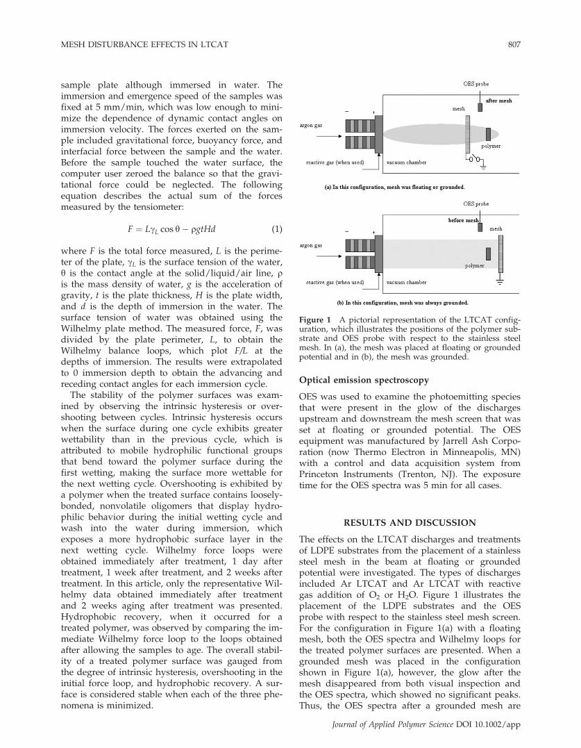
The effects on the LTCAT discharges and treatmentsof LDPE substrates from the placement of a stainlesssteel mesh in the beam at floating or groundedpotential were investigated. The types of dischargesincluded Ar LTCAT and Ar LTCAT with reactivegas addition of O2 or H2O. Figure 1 illustrates theplacement of the LDPE substrates and the OESprobe with respect to the stainless steel mesh screen.For the configuration in Figure 1(a) with a floatingmesh, both the OES spectra and Wilhelmy loops forthe treated polymer surfaces are presented. When agrounded mesh was placed in the configurationshown in Figure 1(a), however, the glow after themesh disappeared from both visual inspection andthe OES spectra, which showed no significant peaks.Thus, the OES spectra after a grounded mesh are
Figure 1 A pictorial representation of the LTCAT config-uration, which illustrates the positions of the polymer sub-strate and OES probe with respect to the stainless steelmesh. In (a), the mesh was placed at floating or groundedpotential and in (b), the mesh was grounded.
MESH DISTURBANCE EFFECTS IN LTCAT 807
Journal of Applied Polymer Science DOI 10.1002/app
not given, but the Wilhelmy loops of the treatedsamples placed after the grounded mesh are pre-sented. For the configuration shown in Figure 1(b)with a grounded mesh, the OES spectra of LTCATand some of the Wilhelmy force loops of the treatedsamples placed in this position are presented. Forcomparison, OES spectra and Wilhelmy loops forLDPE substrates treated without the placement of amesh in LTCAT discharges are also presented. TheWilhelmy force loops for LDPE treated without themesh were obtained from our previous results.1
Wilhelmy loops were also obtained after aging the
samples in ambient air for 2 weeks, to evaluate thepossible hydrophobic recovery of the plasma-treatedsurfaces.
The effects of placing a floating mesh in LTCAT
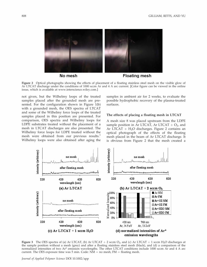
A mesh size 8 was placed upstream from the LDPEsample position in Ar LTCAT, Ar LTCAT þ O2, andAr LTCAT þ H2O discharges. Figure 2 contains anoptical photograph of the effects of the floatingmesh placed in the beam of Ar LTCAT discharge. Itis obvious from Figure 2 that the mesh created a
Figure 2 Optical photographs showing the effects of placement of a floating stainless steel mesh on the visible glow ofAr LTCAT discharge under the conditions of 1000 sccm Ar and 4 A arc current. [Color figure can be viewed in the onlineissue, which is available at www.interscience.wiley.com.]
Figure 3 The OES spectra of (a) Ar LTCAT, (b) Ar LTCAT þ 2 sccm O2, and (c) Ar LTCAT þ 1 sccm H2O discharges atthe sample position without a mesh (grey) and after a floating stainless steel mesh (black), and (d) a comparison of thenormalized intensities of two Ar* emission wavelengths. The other LTCAT conditions include 1000 sccm Ar and 4 A arccurrent. The OES exposure time was 5 min. Code: NM ¼ no mesh; FM ¼ floating mesh.
808 GILLIAM, RITTS, AND YU
Journal of Applied Polymer Science DOI 10.1002/app
significant disturbance in the LTCAT discharge andmuch of the beam seems to be reflected by themesh, even though the mesh size was relativelylarge (� 2.5 mm). OES spectra of the dischargeswithout the mesh and after the floating mesh [con-figuration Fig. 1(a) with floating mesh] wereobtained to examine the changes in photoemittingspecies induced by the mesh. Figure 3 contains OESobservations of (a) Ar LTCAT, (b) Ar LTCAT þ 1sccm O2, and (c) Ar LTCAT þ 1 sccm H2O vapordischarges obtained without a mesh (grey) and aftera floating mesh (black). To clearly elucidate thechanges in Ar* after the floating mesh screen, thenormalized intensities for two wavelengths corre-sponding to Ar* (420 and 763 nm) were obtained foreach discharge using the emission intensities fromAr LTCAT without a mesh. Thus, the normalizedintensities for the two chosen wavelengths for ArLTCAT without a mesh were equal to 1. The OESdata indicate that the intensity of electronicallyexcited Ar atoms, Ar*, was greatly reduced for alldischarges by the placement of the floating meshupstream from the substrate.
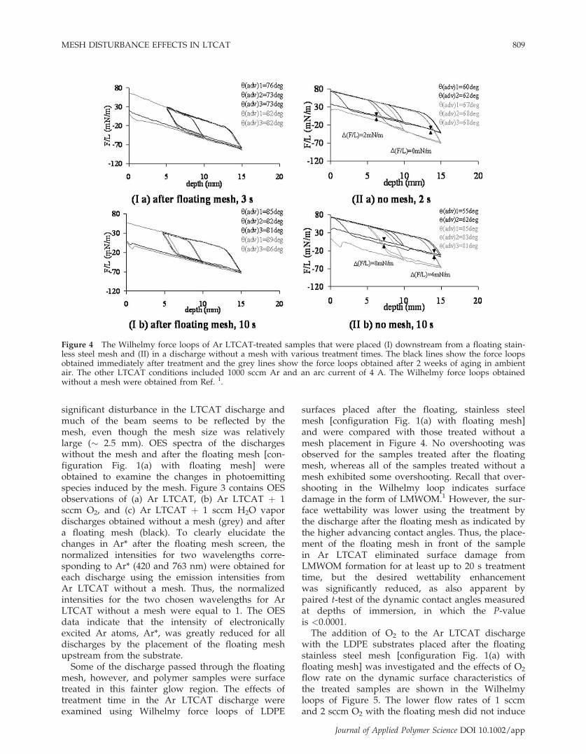
Some of the discharge passed through the floatingmesh, however, and polymer samples were surfacetreated in this fainter glow region. The effects oftreatment time in the Ar LTCAT discharge wereexamined using Wilhelmy force loops of LDPE
surfaces placed after the floating, stainless steelmesh [configuration Fig. 1(a) with floating mesh]and were compared with those treated without amesh placement in Figure 4. No overshooting wasobserved for the samples treated after the floatingmesh, whereas all of the samples treated without amesh exhibited some overshooting. Recall that over-shooting in the Wilhelmy loop indicates surfacedamage in the form of LMWOM.1 However, the sur-face wettability was lower using the treatment bythe discharge after the floating mesh as indicated bythe higher advancing contact angles. Thus, the place-ment of the floating mesh in front of the samplein Ar LTCAT eliminated surface damage fromLMWOM formation for at least up to 20 s treatmenttime, but the desired wettability enhancementwas significantly reduced, as also apparent bypaired t-test of the dynamic contact angles measuredat depths of immersion, in which the P-valueis <0.0001.The addition of O2 to the Ar LTCAT discharge
with the LDPE substrates placed after the floatingstainless steel mesh [configuration Fig. 1(a) withfloating mesh] was investigated and the effects of O2
flow rate on the dynamic surface characteristics ofthe treated samples are shown in the Wilhelmyloops of Figure 5. The lower flow rates of 1 sccmand 2 sccm O2 with the floating mesh did not induce
Figure 4 The Wilhelmy force loops of Ar LTCAT-treated samples that were placed (I) downstream from a floating stain-less steel mesh and (II) in a discharge without a mesh with various treatment times. The black lines show the force loopsobtained immediately after treatment and the grey lines show the force loops obtained after 2 weeks of aging in ambientair. The other LTCAT conditions included 1000 sccm Ar and an arc current of 4 A. The Wilhelmy force loops obtainedwithout a mesh were obtained from Ref. 1.
MESH DISTURBANCE EFFECTS IN LTCAT 809
Journal of Applied Polymer Science DOI 10.1002/app
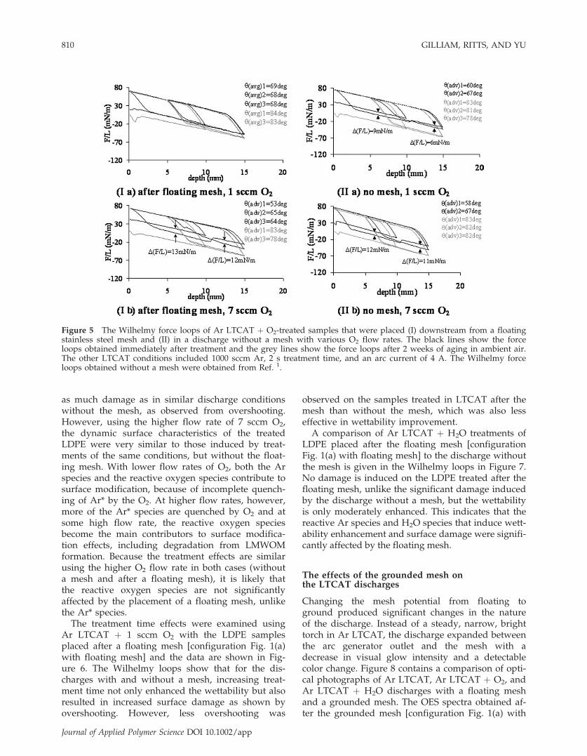
as much damage as in similar discharge conditionswithout the mesh, as observed from overshooting.However, using the higher flow rate of 7 sccm O2,the dynamic surface characteristics of the treatedLDPE were very similar to those induced by treat-ments of the same conditions, but without the float-ing mesh. With lower flow rates of O2, both the Arspecies and the reactive oxygen species contribute tosurface modification, because of incomplete quench-ing of Ar* by the O2. At higher flow rates, however,more of the Ar* species are quenched by O2 and atsome high flow rate, the reactive oxygen speciesbecome the main contributors to surface modifica-tion effects, including degradation from LMWOMformation. Because the treatment effects are similarusing the higher O2 flow rate in both cases (withouta mesh and after a floating mesh), it is likely thatthe reactive oxygen species are not significantlyaffected by the placement of a floating mesh, unlikethe Ar* species.
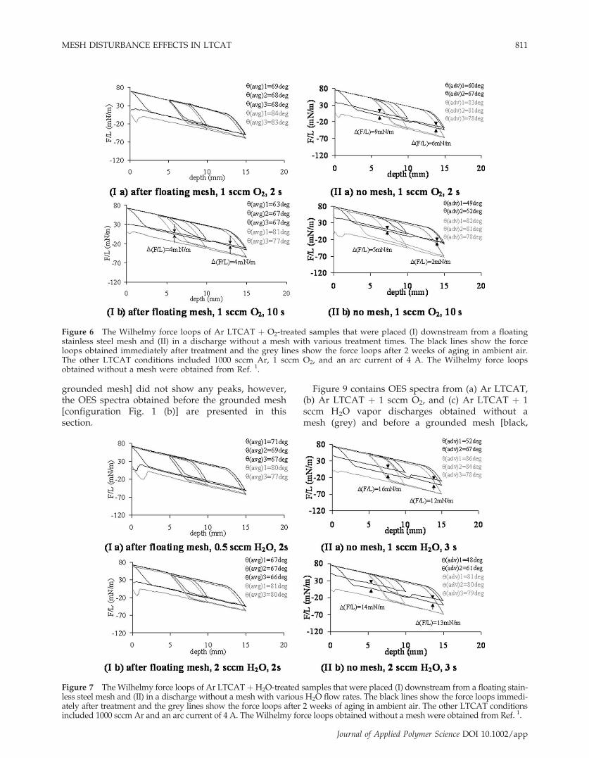
The treatment time effects were examined usingAr LTCAT þ 1 sccm O2 with the LDPE samplesplaced after a floating mesh [configuration Fig. 1(a)with floating mesh] and the data are shown in Fig-ure 6. The Wilhelmy loops show that for the dis-charges with and without a mesh, increasing treat-ment time not only enhanced the wettability but alsoresulted in increased surface damage as shown byovershooting. However, less overshooting was
observed on the samples treated in LTCAT after themesh than without the mesh, which was also lesseffective in wettability improvement.A comparison of Ar LTCAT þ H2O treatments of
LDPE placed after the floating mesh [configurationFig. 1(a) with floating mesh] to the discharge withoutthe mesh is given in the Wilhelmy loops in Figure 7.No damage is induced on the LDPE treated after thefloating mesh, unlike the significant damage inducedby the discharge without a mesh, but the wettabilityis only moderately enhanced. This indicates that thereactive Ar species and H2O species that induce wett-ability enhancement and surface damage were signifi-cantly affected by the floating mesh.
The effects of the grounded mesh onthe LTCAT discharges
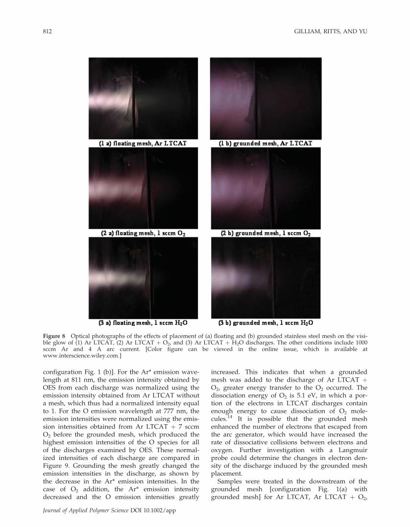
Changing the mesh potential from floating toground produced significant changes in the natureof the discharge. Instead of a steady, narrow, brighttorch in Ar LTCAT, the discharge expanded betweenthe arc generator outlet and the mesh with adecrease in visual glow intensity and a detectablecolor change. Figure 8 contains a comparison of opti-cal photographs of Ar LTCAT, Ar LTCAT þ O2, andAr LTCAT þ H2O discharges with a floating meshand a grounded mesh. The OES spectra obtained af-ter the grounded mesh [configuration Fig. 1(a) with
Figure 5 The Wilhelmy force loops of Ar LTCAT þ O2-treated samples that were placed (I) downstream from a floatingstainless steel mesh and (II) in a discharge without a mesh with various O2 flow rates. The black lines show the forceloops obtained immediately after treatment and the grey lines show the force loops after 2 weeks of aging in ambient air.The other LTCAT conditions included 1000 sccm Ar, 2 s treatment time, and an arc current of 4 A. The Wilhelmy forceloops obtained without a mesh were obtained from Ref. 1.
810 GILLIAM, RITTS, AND YU
Journal of Applied Polymer Science DOI 10.1002/app
grounded mesh] did not show any peaks, however,the OES spectra obtained before the grounded mesh[configuration Fig. 1 (b)] are presented in thissection.
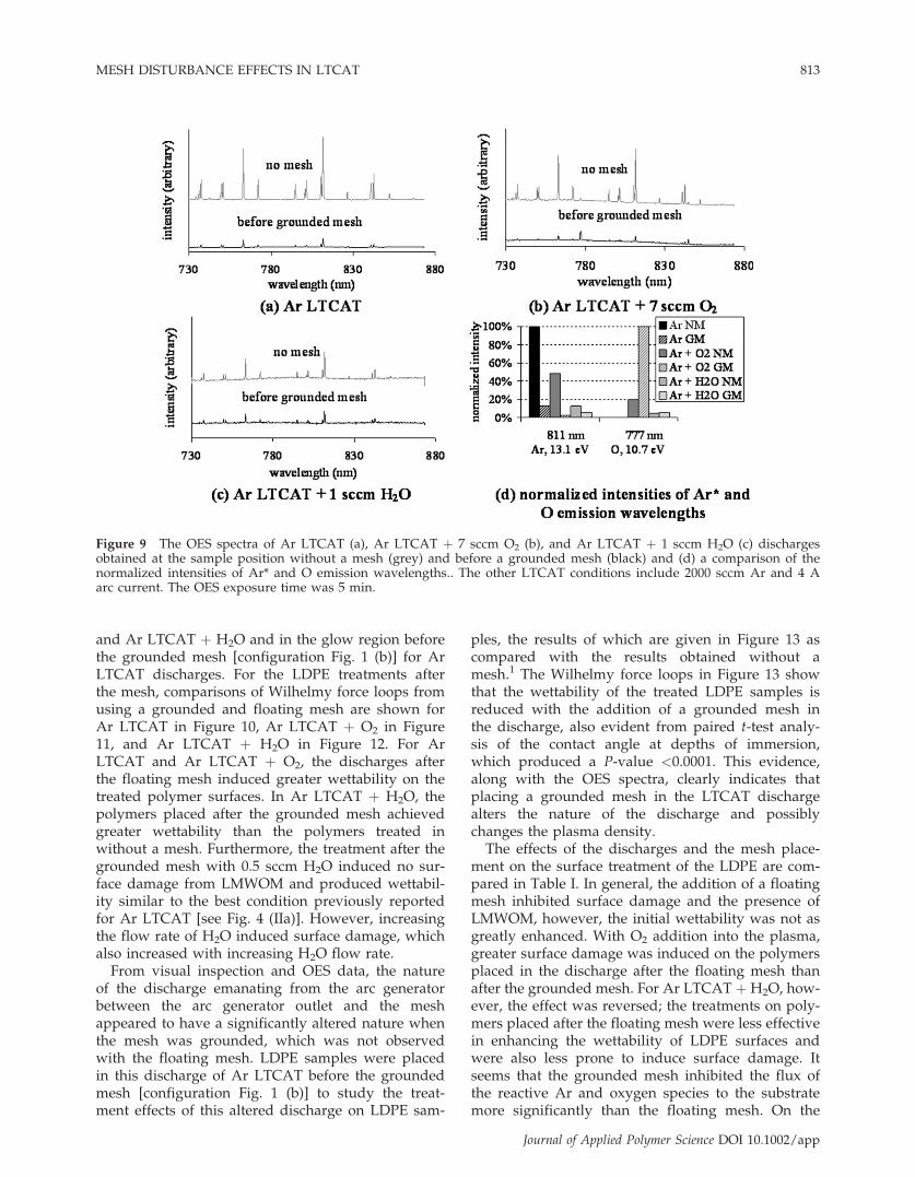
Figure 9 contains OES spectra from (a) Ar LTCAT,(b) Ar LTCAT þ 1 sccm O2, and (c) Ar LTCAT þ 1sccm H2O vapor discharges obtained without amesh (grey) and before a grounded mesh [black,
Figure 6 The Wilhelmy force loops of Ar LTCAT þ O2-treated samples that were placed (I) downstream from a floatingstainless steel mesh and (II) in a discharge without a mesh with various treatment times. The black lines show the forceloops obtained immediately after treatment and the grey lines show the force loops after 2 weeks of aging in ambient air.The other LTCAT conditions included 1000 sccm Ar, 1 sccm O2, and an arc current of 4 A. The Wilhelmy force loopsobtained without a mesh were obtained from Ref. 1.
Figure 7 TheWilhelmy force loops of Ar LTCATþH2O-treated samples that were placed (I) downstream from a floating stain-less steel mesh and (II) in a discharge without a mesh with various H2O flow rates. The black lines show the force loops immedi-ately after treatment and the grey lines show the force loops after 2 weeks of aging in ambient air. The other LTCAT conditionsincluded 1000 sccm Ar and an arc current of 4 A. The Wilhelmy force loops obtained without a mesh were obtained from Ref. 1.
MESH DISTURBANCE EFFECTS IN LTCAT 811
Journal of Applied Polymer Science DOI 10.1002/app
configuration Fig. 1 (b)]. For the Ar* emission wave-length at 811 nm, the emission intensity obtained byOES from each discharge was normalized using theemission intensity obtained from Ar LTCAT withouta mesh, which thus had a normalized intensity equalto 1. For the O emission wavelength at 777 nm, theemission intensities were normalized using the emis-sion intensities obtained from Ar LTCAT þ 7 sccmO2 before the grounded mesh, which produced thehighest emission intensities of the O species for allof the discharges examined by OES. These normal-ized intensities of each discharge are compared inFigure 9. Grounding the mesh greatly changed theemission intensities in the discharge, as shown bythe decrease in the Ar* emission intensities. In thecase of O2 addition, the Ar* emission intensitydecreased and the O emission intensities greatly
increased. This indicates that when a groundedmesh was added to the discharge of Ar LTCAT þO2, greater energy transfer to the O2 occurred. Thedissociation energy of O2 is 5.1 eV, in which a por-tion of the electrons in LTCAT discharges containenough energy to cause dissociation of O2 mole-cules.14 It is possible that the grounded meshenhanced the number of electrons that escaped fromthe arc generator, which would have increased therate of dissociative collisions between electrons andoxygen. Further investigation with a Langmuirprobe could determine the changes in electron den-sity of the discharge induced by the grounded meshplacement.Samples were treated in the downstream of the
grounded mesh [configuration Fig. 1(a) withgrounded mesh] for Ar LTCAT, Ar LTCAT þ O2,
Figure 8 Optical photographs of the effects of placement of (a) floating and (b) grounded stainless steel mesh on the visi-ble glow of (1) Ar LTCAT, (2) Ar LTCAT þ O2, and (3) Ar LTCAT þ H2O discharges. The other conditions include 1000sccm Ar and 4 A arc current. [Color figure can be viewed in the online issue, which is available atwww.interscience.wiley.com.]
812 GILLIAM, RITTS, AND YU
Journal of Applied Polymer Science DOI 10.1002/app
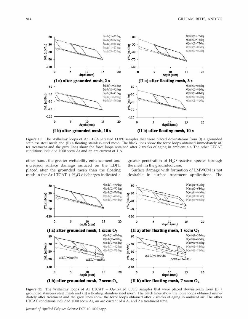
and Ar LTCAT þ H2O and in the glow region beforethe grounded mesh [configuration Fig. 1 (b)] for ArLTCAT discharges. For the LDPE treatments afterthe mesh, comparisons of Wilhelmy force loops fromusing a grounded and floating mesh are shown forAr LTCAT in Figure 10, Ar LTCAT þ O2 in Figure11, and Ar LTCAT þ H2O in Figure 12. For ArLTCAT and Ar LTCAT þ O2, the discharges afterthe floating mesh induced greater wettability on thetreated polymer surfaces. In Ar LTCAT þ H2O, thepolymers placed after the grounded mesh achievedgreater wettability than the polymers treated inwithout a mesh. Furthermore, the treatment after thegrounded mesh with 0.5 sccm H2O induced no sur-face damage from LMWOM and produced wettabil-ity similar to the best condition previously reportedfor Ar LTCAT [see Fig. 4 (IIa)]. However, increasingthe flow rate of H2O induced surface damage, whichalso increased with increasing H2O flow rate.
From visual inspection and OES data, the natureof the discharge emanating from the arc generatorbetween the arc generator outlet and the meshappeared to have a significantly altered nature whenthe mesh was grounded, which was not observedwith the floating mesh. LDPE samples were placedin this discharge of Ar LTCAT before the groundedmesh [configuration Fig. 1 (b)] to study the treat-ment effects of this altered discharge on LDPE sam-
ples, the results of which are given in Figure 13 ascompared with the results obtained without amesh.1 The Wilhelmy force loops in Figure 13 showthat the wettability of the treated LDPE samples isreduced with the addition of a grounded mesh inthe discharge, also evident from paired t-test analy-sis of the contact angle at depths of immersion,which produced a P-value <0.0001. This evidence,along with the OES spectra, clearly indicates thatplacing a grounded mesh in the LTCAT dischargealters the nature of the discharge and possiblychanges the plasma density.The effects of the discharges and the mesh place-
ment on the surface treatment of the LDPE are com-pared in Table I. In general, the addition of a floatingmesh inhibited surface damage and the presence ofLMWOM, however, the initial wettability was not asgreatly enhanced. With O2 addition into the plasma,greater surface damage was induced on the polymersplaced in the discharge after the floating mesh thanafter the grounded mesh. For Ar LTCAT þ H2O, how-ever, the effect was reversed; the treatments on poly-mers placed after the floating mesh were less effectivein enhancing the wettability of LDPE surfaces andwere also less prone to induce surface damage. Itseems that the grounded mesh inhibited the flux ofthe reactive Ar and oxygen species to the substratemore significantly than the floating mesh. On the
Figure 9 The OES spectra of Ar LTCAT (a), Ar LTCAT þ 7 sccm O2 (b), and Ar LTCAT þ 1 sccm H2O (c) dischargesobtained at the sample position without a mesh (grey) and before a grounded mesh (black) and (d) a comparison of thenormalized intensities of Ar* and O emission wavelengths.. The other LTCAT conditions include 2000 sccm Ar and 4 Aarc current. The OES exposure time was 5 min.
MESH DISTURBANCE EFFECTS IN LTCAT 813
Journal of Applied Polymer Science DOI 10.1002/app
other hand, the greater wettability enhancement andincreased surface damage induced on the LDPEplaced after the grounded mesh than the floatingmesh in the Ar LTCAT þ H2O discharges indicated a
greater penetration of H2O reactive species throughthe mesh in the grounded case.Surface damage with formation of LMWOM is not
desirable in surface treatment applications. The
Figure 10 The Wilhelmy loops of Ar LTCAT-treated LDPE samples that were placed downstream from (I) a groundedstainless steel mesh and (II) a floating stainless steel mesh. The black lines show the force loops obtained immediately af-ter treatment and the grey lines show the force loops obtained after 2 weeks of aging in ambient air. The other LTCATconditions included 1000 sccm Ar and an arc current of 4 A.
Figure 11 The Wilhelmy loops of Ar LTCAT þ O2-treated LDPE samples that were placed downstream from (I) agrounded stainless steel mesh and (II) a floating stainless steel mesh. The black lines show the force loops obtained imme-diately after treatment and the grey lines show the force loops obtained after 2 weeks of aging in ambient air. The otherLTCAT conditions included 1000 sccm Ar, an arc current of 4 A, and 2 s treatment time.
814 GILLIAM, RITTS, AND YU
Journal of Applied Polymer Science DOI 10.1002/app
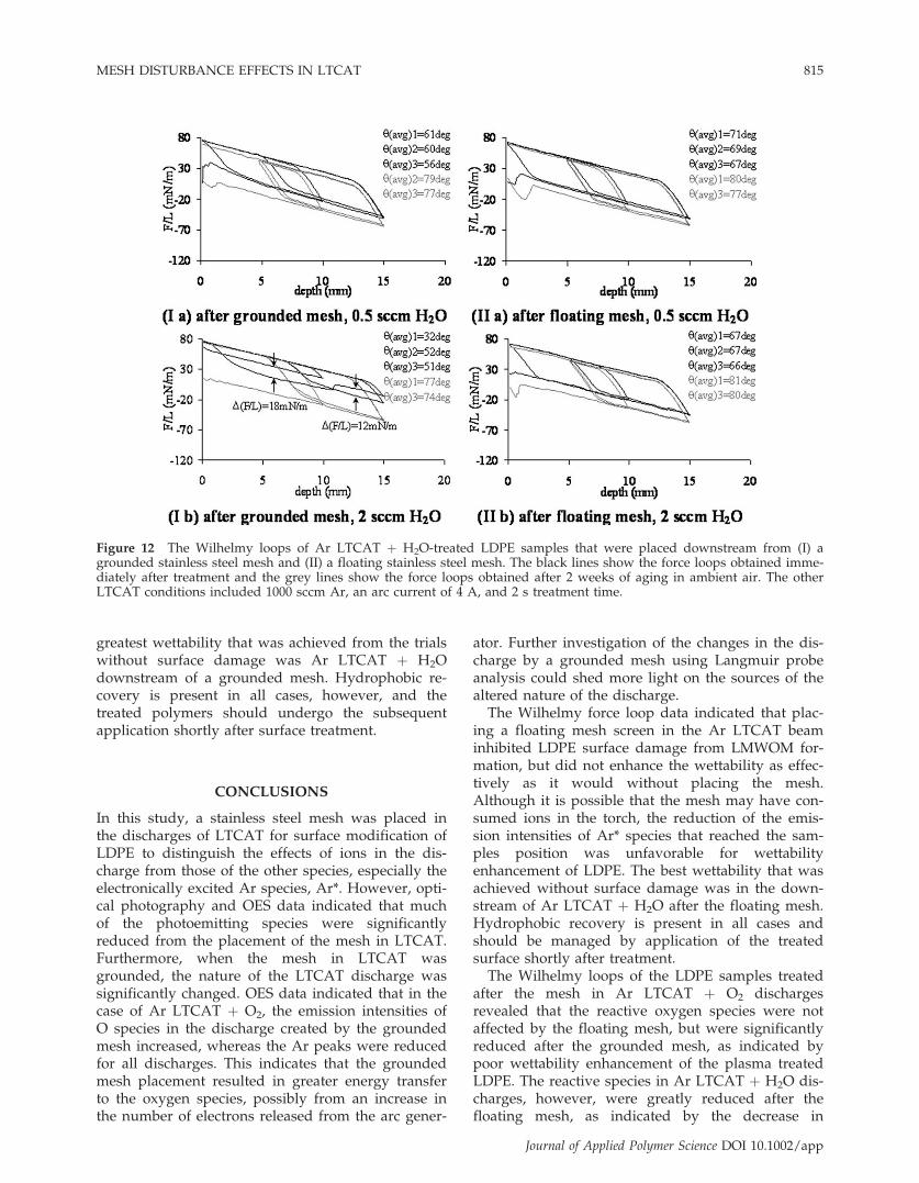
greatest wettability that was achieved from the trialswithout surface damage was Ar LTCAT þ H2Odownstream of a grounded mesh. Hydrophobic re-covery is present in all cases, however, and thetreated polymers should undergo the subsequentapplication shortly after surface treatment.
CONCLUSIONS
In this study, a stainless steel mesh was placed inthe discharges of LTCAT for surface modification ofLDPE to distinguish the effects of ions in the dis-charge from those of the other species, especially theelectronically excited Ar species, Ar*. However, opti-cal photography and OES data indicated that muchof the photoemitting species were significantlyreduced from the placement of the mesh in LTCAT.Furthermore, when the mesh in LTCAT wasgrounded, the nature of the LTCAT discharge wassignificantly changed. OES data indicated that in thecase of Ar LTCAT þ O2, the emission intensities ofO species in the discharge created by the groundedmesh increased, whereas the Ar peaks were reducedfor all discharges. This indicates that the groundedmesh placement resulted in greater energy transferto the oxygen species, possibly from an increase inthe number of electrons released from the arc gener-
ator. Further investigation of the changes in the dis-charge by a grounded mesh using Langmuir probeanalysis could shed more light on the sources of thealtered nature of the discharge.The Wilhelmy force loop data indicated that plac-
ing a floating mesh screen in the Ar LTCAT beaminhibited LDPE surface damage from LMWOM for-mation, but did not enhance the wettability as effec-tively as it would without placing the mesh.Although it is possible that the mesh may have con-sumed ions in the torch, the reduction of the emis-sion intensities of Ar* species that reached the sam-ples position was unfavorable for wettabilityenhancement of LDPE. The best wettability that wasachieved without surface damage was in the down-stream of Ar LTCAT þ H2O after the floating mesh.Hydrophobic recovery is present in all cases andshould be managed by application of the treatedsurface shortly after treatment.The Wilhelmy loops of the LDPE samples treated
after the mesh in Ar LTCAT þ O2 dischargesrevealed that the reactive oxygen species were notaffected by the floating mesh, but were significantlyreduced after the grounded mesh, as indicated bypoor wettability enhancement of the plasma treatedLDPE. The reactive species in Ar LTCAT þ H2O dis-charges, however, were greatly reduced after thefloating mesh, as indicated by the decrease in
Figure 12 The Wilhelmy loops of Ar LTCAT þ H2O-treated LDPE samples that were placed downstream from (I) agrounded stainless steel mesh and (II) a floating stainless steel mesh. The black lines show the force loops obtained imme-diately after treatment and the grey lines show the force loops obtained after 2 weeks of aging in ambient air. The otherLTCAT conditions included 1000 sccm Ar, an arc current of 4 A, and 2 s treatment time.
MESH DISTURBANCE EFFECTS IN LTCAT 815
Journal of Applied Polymer Science DOI 10.1002/app

wettability and surface damage on the treated poly-mers. LDPE samples treated after a grounded meshin the Ar LTCAT þ H2O discharges, however, exhib-ited much improved wettability enhancement withless surface damage than those treated withoutusing a mesh or after a floating mesh. For samplestreated in the Ar LTCAT discharge before agrounded mesh, the wettability enhancement andinduced surface damage were significantly reduced
in comparison with the treatments without a mesh.A natural continuation of this study would involveinvestigation of the chemical and physical surfacechanges resulting from the plasma treatments.These findings indicate a most important message,
which is that careful consideration needs to make whenapplying any such disturbance in a plasma dischargebecause the nature of the discharge as well as the desir-able process outcomes can be significantly altered.
Figure 13 The Wilhelmy loops of Ar LTCAT-treated samples that were placed (I) in the discharge created between thearc generator and a grounded, stainless steel mesh and (II) in a discharge without a mesh with various treatment times.The black lines show the force loops obtained immediately after treatment and the grey lines show the force loopsobtained after 2 weeks of aging in ambient air. The treatment conditions were 1000 sccm Ar and 4 A arc current. The Wil-helmy force loops obtained without a mesh were obtained FROM Ref. 1.
TABLE ISummary of Surface Changes Induced from LTCAT Plasma Treatments
Plasmas Evaluation
Placement position of LDPE samples
No meshDownstream
of floating meshDownstream ofgrounded mesh
Upstream ofgrounded mesh
Ar LTCAT (2 and 3 s) Initial contact angle y ¼ 60� y ¼ 76� y ¼ 83� y ¼ 85�
Overshooting(LMWOM damage)
y increase by 2� Not present Not present Not present
Hydrophobic recovery y increase by 6� y increase by 7� y increase by 4� y increase by 4�
Ar LTCAT þ1sccm O2 (2 s)
Initial contact angle y ¼ 60� y ¼ 69� y ¼ 79� n/aOvershooting(LMWOM damage)
y increase by 7� Not present Not present n/a
Hydrophobic recovery y increase by 16� y increase by 15� y increase by 7� n/aAr LTCAT þ 2 sccmH2O (2 and 3 s)
Initial contact angle y ¼ 48� y ¼ 67� y ¼ 32� n/aOvershooting(LMWOM damage)
y increase by 13� Not present y increase by 20� n/a
Hydrophobic recovery y increase by 20� y increase by 14� y increase by 25� n/a
816 GILLIAM, RITTS, AND YU
Journal of Applied Polymer Science DOI 10.1002/app

The authors would like to express their appreciation to Prof.H. Yasuda at University of Missouri-Columbia for his help-ful discussions of this work.
References
1. Gilliam, M. A.; Yu, Q. J Appl Polym Sci 2005, 99, 2528.2. Ratner, B. D.; Chilkoti, A.; Lopez, G. P. In Plasma Deposition,
Treatment, and Etching of Polymers; D’agostino, R., Ed.; Aca-demic Press: Boston, 1990; pp 463–516.
3. Penn, L. S.; Wang, H. Polym Adv Technol 1994, 5, 809.4. Wertheimer, M. R.; Martinu, L.; Liston, E. M. In Handbook of
Thin Film Process Technology; Glocker, D. A., Ed.; Institute ofPhysics Publishing: Bristol, 2002; Vol. 2, pp E3.0:1–E3.0:38.
5. Durand, A. M. LE VIDE, Sci Tech Appl 1997, 53, 242.6. Weikart, C. M.; Yasuda, H. K. J Polym Sci A 2000, 38, 3028.
7. Gilliam, M. A.; Yu, Q.; In Encyclopedia of Chemical Process-ing; Lee, S., Ed.; Taylor & Francis, 2007.
8. Egitto, F. D.; Matienzo, L. J. IBM J Res Develop 1994, 38,423.
9. Truica-Marasescu, F.-E.; Wertheimer, M. R. Macromol ChemPhys 2005, 206, 744.
10. Butoi, C. I.; Mackie, N. M.; Mccurdy, P. R.; Peers, J. R. D.;Fisher, E. R. Plasm Polym 1999, 4, 77.
11. Yu, Q. S.; Reddy, C. M.; Meives, M. F.; Yasuda, H. K. J PolymSci: Part A: Polym Chem 1999, 37, 4432.
12. Fusselman, S. P.; Yasuda, H. K. Plasma Chem Plasma Process,1994, 14, 251.
13. Yu, Q. S.; Yasuda, H. K. Plasma Chem Plasma Process 1998,18, 461.
14. Yasuda, H. Luminous Chemical Vapor Deposition and Inter-face Engineering; Marcel Dekker: New York, 2005; p 339.
MESH DISTURBANCE EFFECTS IN LTCAT 817
Journal of Applied Polymer Science DOI 10.1002/app