The MeerKAT Digital Back End
61
The MeerKAT Digital Back End Francois Kapp – SKA SA Manager: Digital Systems [email protected] On behalf of the DBE team: Present: A Barta, E Bauermeister, P Gibbs, H Kriel, O Mahgoub, S Malan, J Manley, A Martens, V Moss, W New, P Prozesky, S Rajan, A Rust, W Rust, L Sofeya, M Welz Past: D George, P Herselman, A Langman, C Kritzinger, S Mthembu, R van Rooyen
Transcript of The MeerKAT Digital Back End
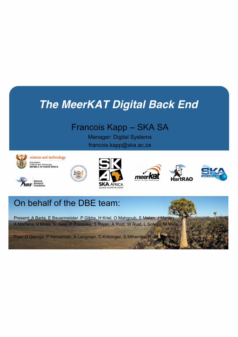
The MeerKAT Digital Back End
Francois Kapp – SKA SA Manager: Digital Systems [email protected]
On behalf of the DBE team: Present: A Barta, E Bauermeister, P Gibbs, H Kriel, O Mahgoub, S Malan, J Manley, A Martens, V Moss, W New, P Prozesky, S Rajan, A Rust, W Rust, L Sofeya, M Welz Past: D George, P Herselman, A Langman, C Kritzinger, S Mthembu, R van Rooyen
• CASPER: An evolution from KAT7 • MeerKAT Digitiser • MeerKAT Time and Frequency Reference Sub-
system • MeerKAT Correlator/Beamformer • Adventures in collaborations
Introduction
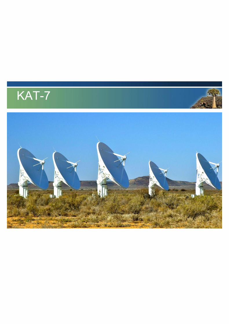
KAT-7
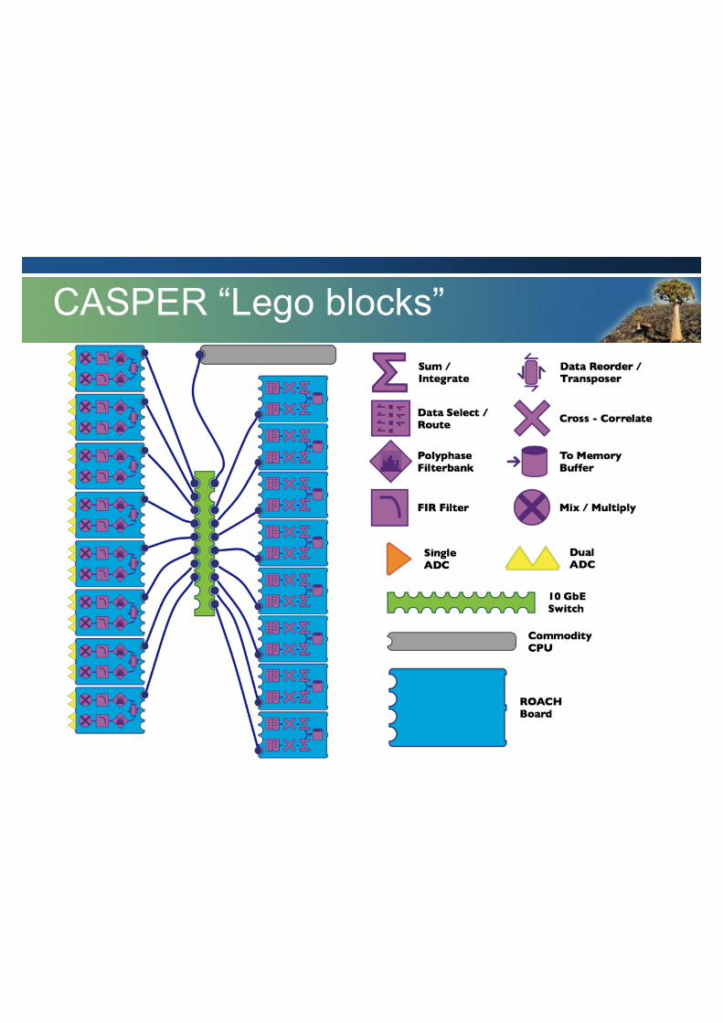
CASPER “Lego blocks”

Simulink View
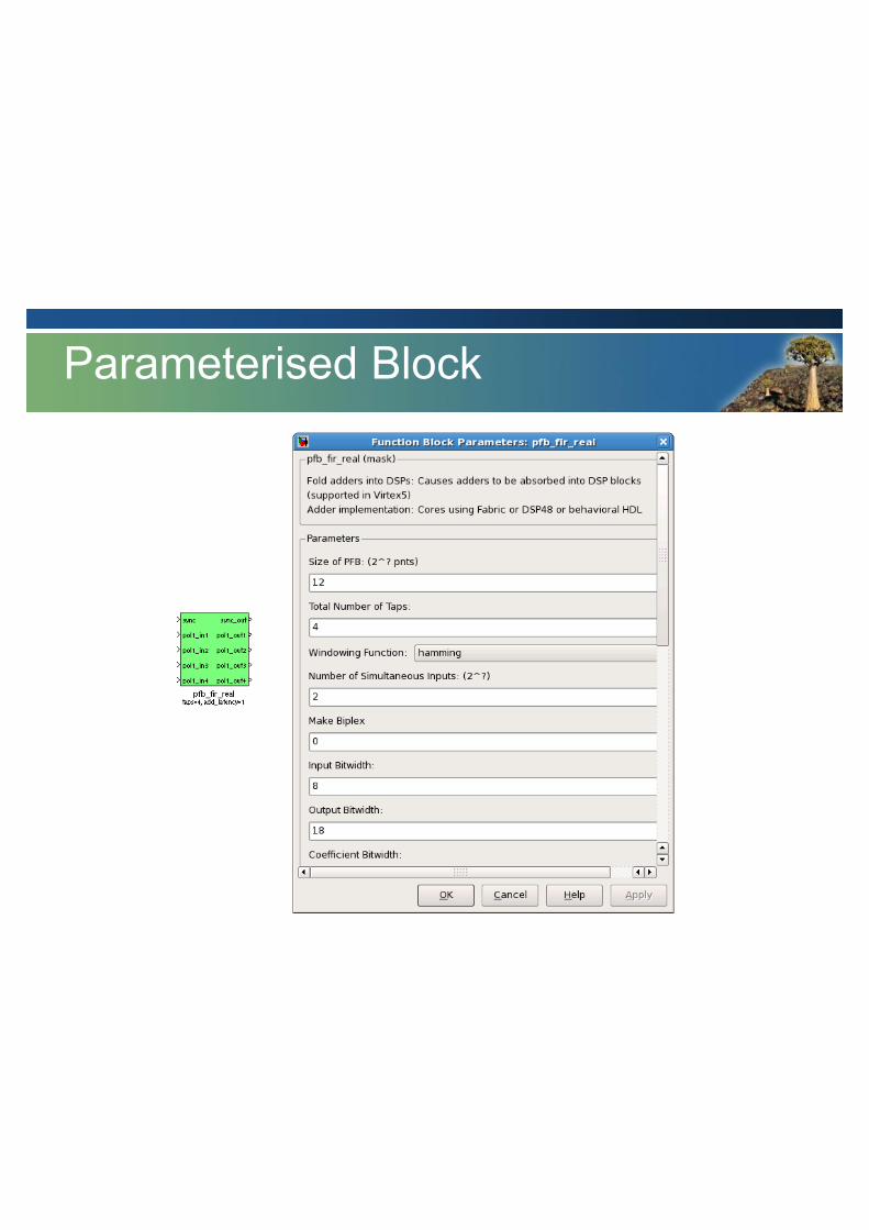
Parameterised Block
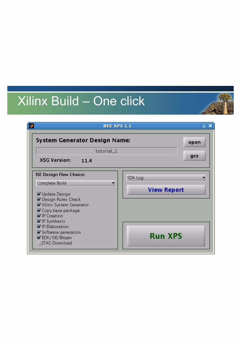
Xilinx Build – One click


KAT-7 Block Diagram
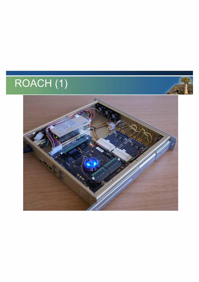
ROACH (1)

• CASPER architecture • 16 x ROACH v-> 8 x F, 8 x X • 10GbE interconnect • Analogue Fibre to Central Processing
ROACH (Reconfigurable Open Architecture Computing Hardware) based
KAT-7 DBE Implementation
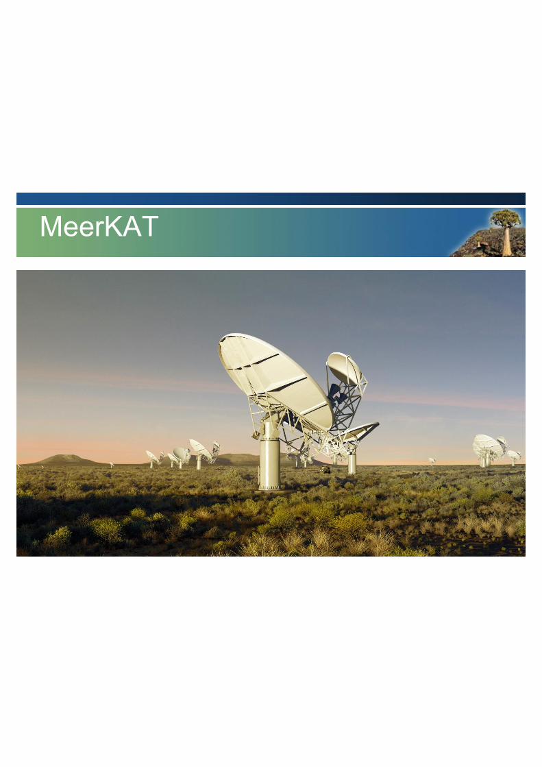
MeerKAT
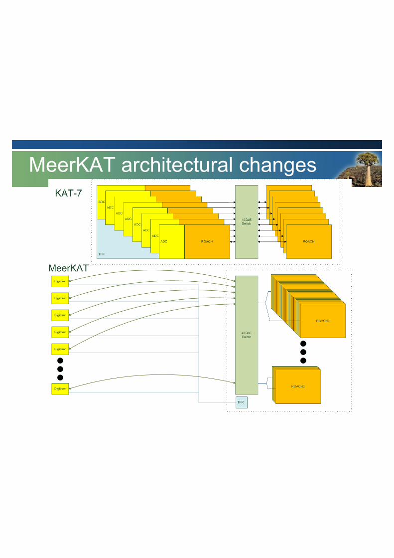
MeerKAT architectural changes
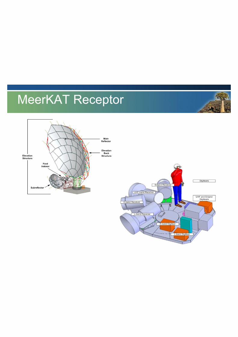
MeerKAT Receptor

MeerKAT TFR
Time and Frequency Reference Sub-system
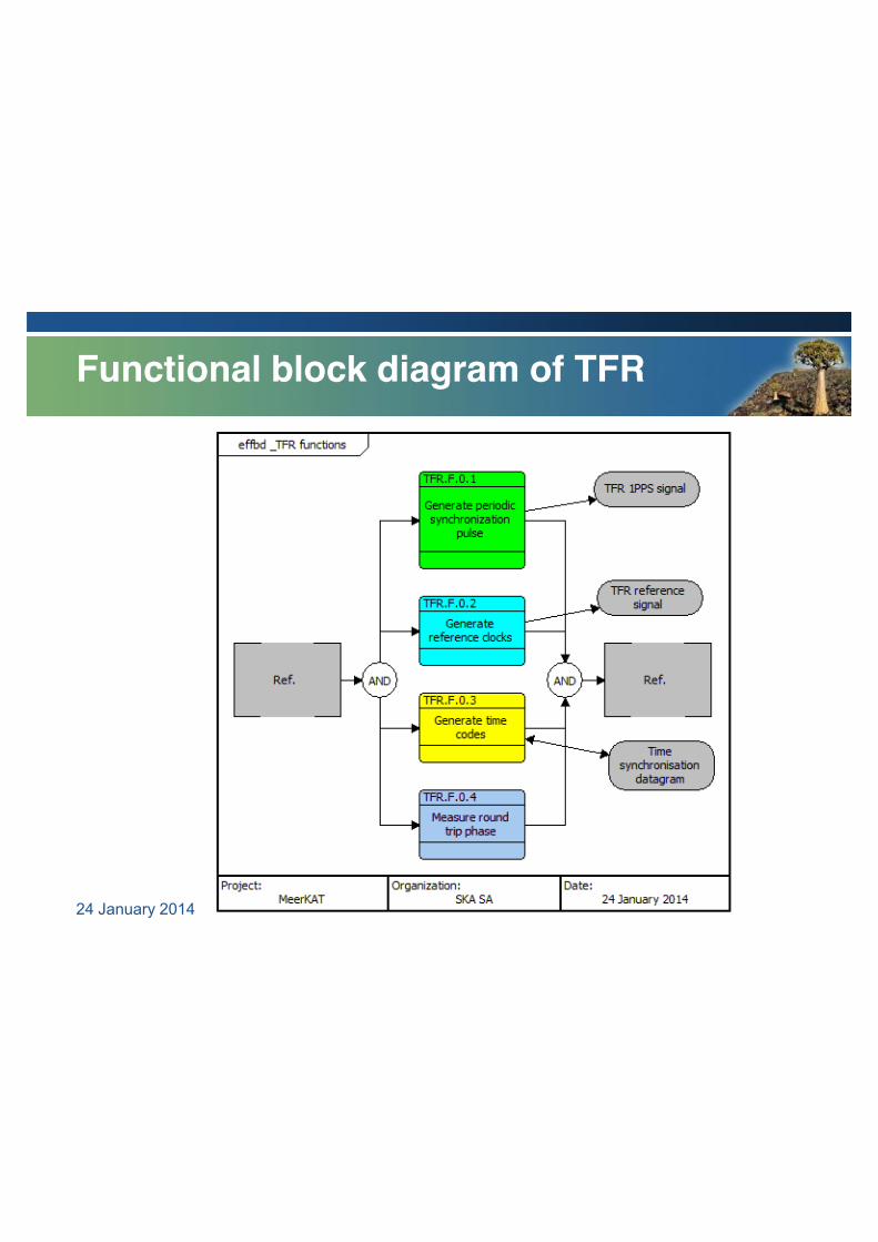
Functional block diagram of TFR
24 January 2014
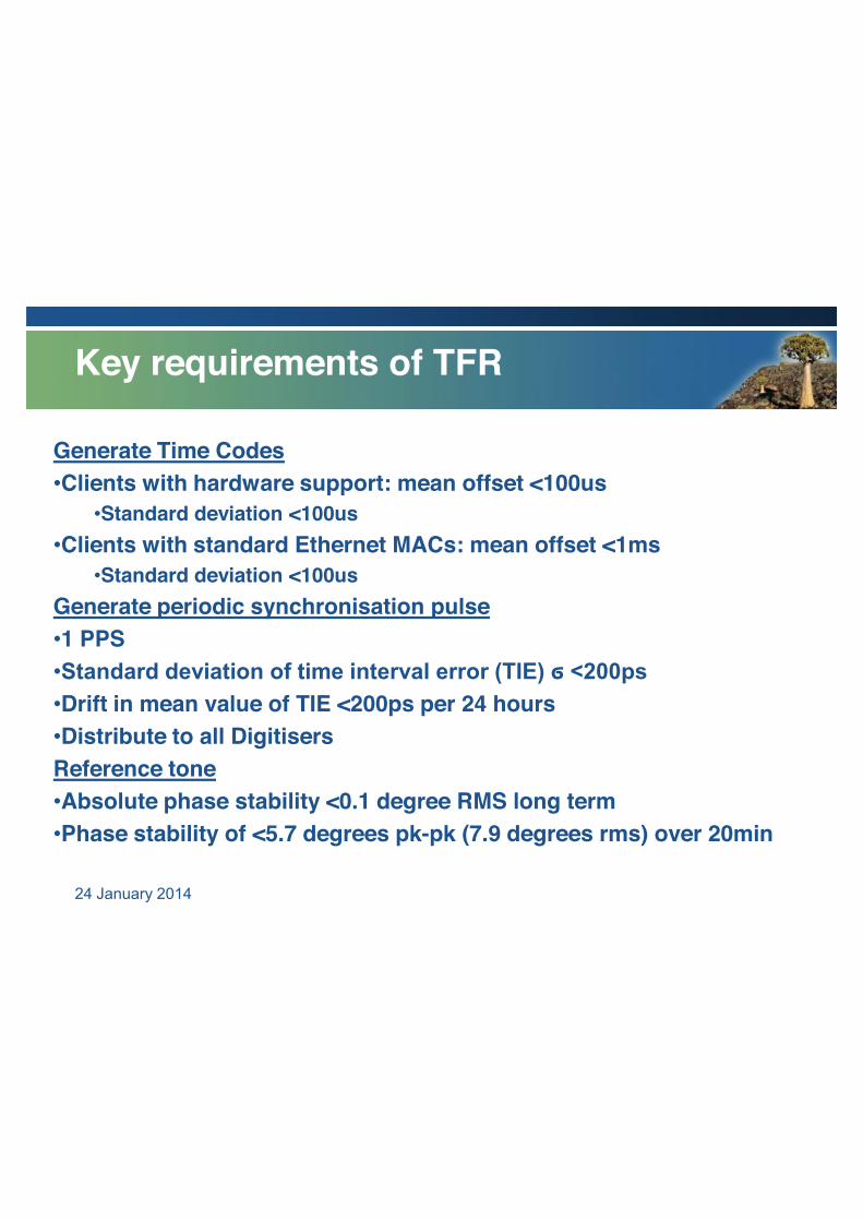
Key requirements of TFR
Generate Time Codes •Clients with hardware support: mean offset <100us
•Standard deviation <100us •Clients with standard Ethernet MACs: mean offset <1ms
•Standard deviation <100us Generate periodic synchronisation pulse •1 PPS •Standard deviation of time interval error (TIE) ϭ <200ps •Drift in mean value of TIE <200ps per 24 hours •Distribute to all Digitisers Reference tone •Absolute phase stability <0.1 degree RMS long term •Phase stability of <5.7 degrees pk-pk (7.9 degrees rms) over 20min
24 January 2014
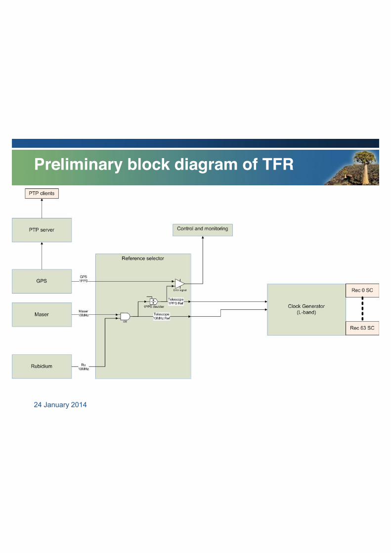
Preliminary block diagram of TFR
24 January 2014
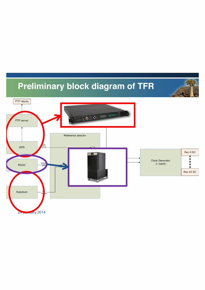
Preliminary block diagram of TFR
24 January 2014
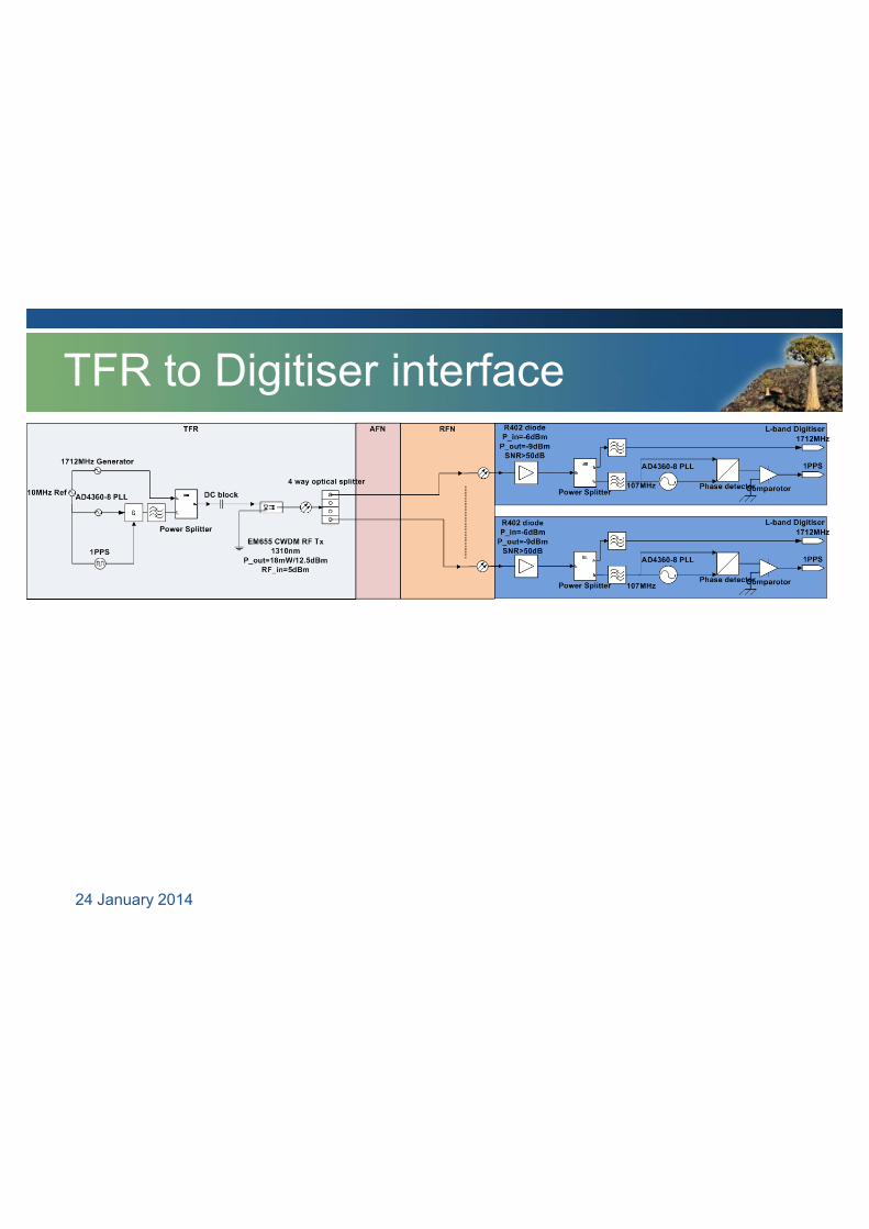
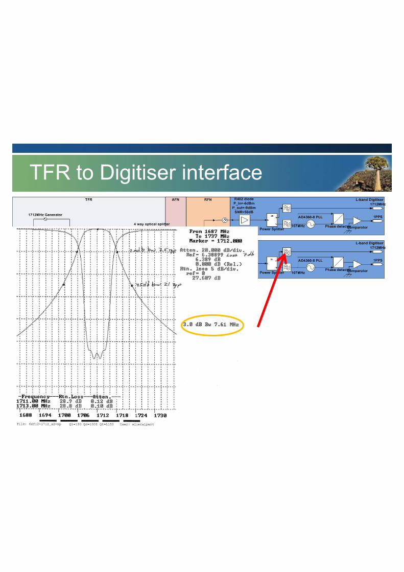
TFR to Digitiser interface
24 January 2014
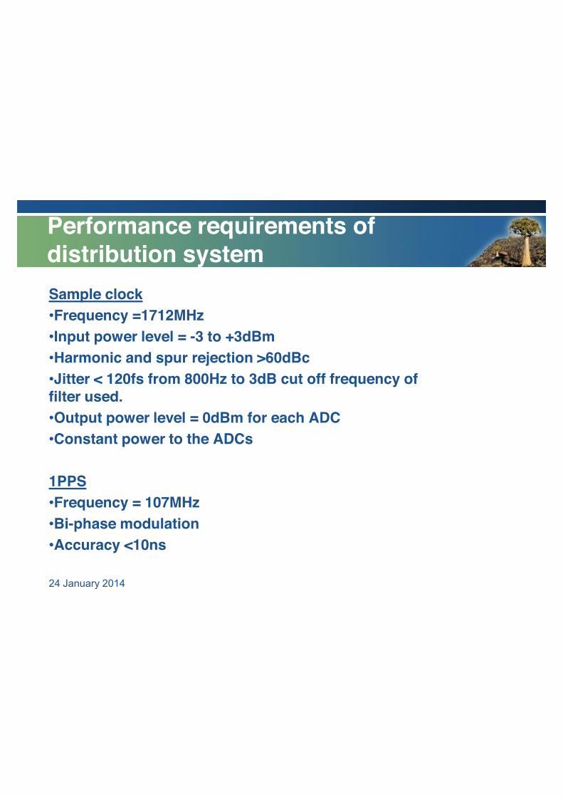
Performance requirements of distribution system Sample clock •Frequency =1712MHz •Input power level = -3 to +3dBm •Harmonic and spur rejection >60dBc •Jitter < 120fs from 800Hz to 3dB cut off frequency of filter used. •Output power level = 0dBm for each ADC •Constant power to the ADCs
1PPS •Frequency = 107MHz •Bi-phase modulation •Accuracy <10ns 24 January 2014
TFR to Digitiser interface
24 January 2014
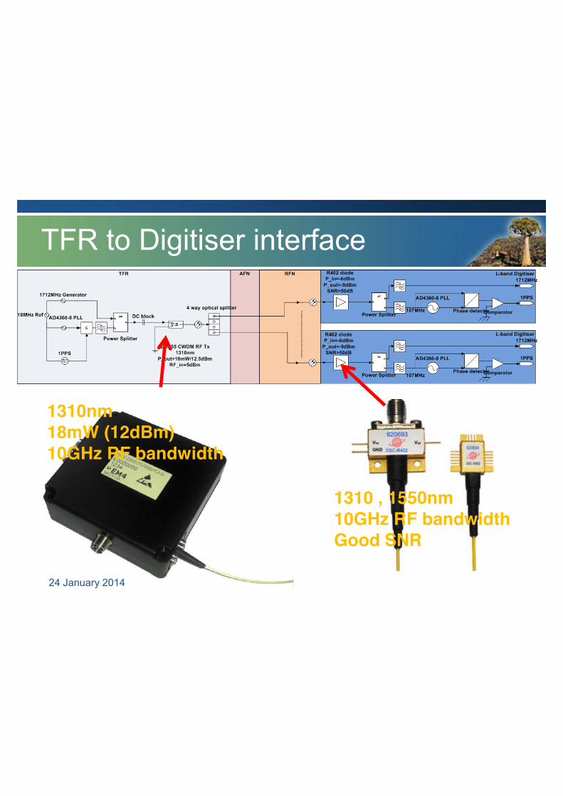
1310nm 18mW (12dBm) 10GHz RF bandwidth
1310 , 1550nm 10GHz RF bandwidth Good SNR
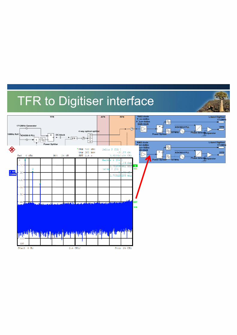
TFR to Digitiser interface
24 January 2014
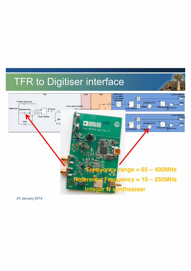
Frequency range = 65 – 400MHz Reference Frequency = 10 – 250MHz
Integer N synthesiser
TFR to Digitiser interface
24 January 2014
TFR to Digitiser interface
24 January 2014
Running ...
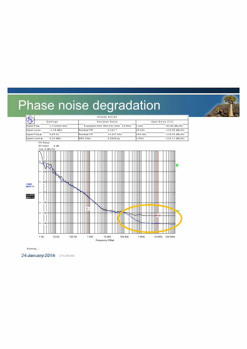
P H A S E N O I S E
S e t t i ngs R e s i dua l N o i s e S po t N o i s e [T 2 ]
Signal Freq: 1 .712000 GHz Evaluation from 800.321 Hzto 10 MHz 1 kHz -92.85 dBc/Hz
Signal Level: -1 .18 dBm Res idual PM 0.161 ° 10 kHz -115.05 dBc/Hz
Signal Freq Δ: 0.69 Hz Res idual FM 14.247 kHz 100 kHz -118.55 dBc/Hz
Signal Level Δ: 0.22 dBm RMS Jitter 0 .2608 ps 1 MHz -124.11 dBc/Hz
PH Noise RF A tten 0 dB Top 0 dBc/Hz
10 Hz 100 Hz 1 kHz 10 kHz 100 kHz 1 MHz 10 MHz1 Hz 100 MHz
-140
-120
-100
-80
-60
-40
-20
EL1
EL2
1 VIEWSMTH 1%
2 CLRW RSMTH 1%
A
EXT
Frequency Offset
Date: 3.DEC.2013 17:29:56
Phase noise degradation
24 January 2014
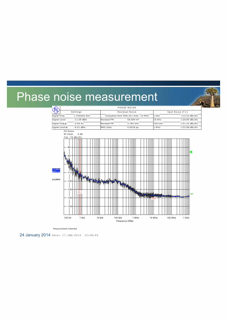
Phase noise measurement
24 January 2014
Measurement A borted
P H A S E N O I S E
S e t t i ngs R e s i dua l N o i s e S po t N o i s e [T 1 ]
Signal Freq: 1 .700000 GHz Evaluation from 800.321 Hzto 10 MHz 1 kHz -112.42 dBc/Hz
Signal Level: -11.08 dBm Res idual PM 56.694 m° 10 kHz -120.85 dBc/Hz
Signal Freq Δ: -2 .06 Hz Res idual FM 3.785 kHz 100 kHz -121.22 dBc/Hz
Signal Level Δ: -0 .01 dBm RMS Jitter 0 .0926 ps 1 MHz -132.98 dBc/Hz
PH Noise RF A tten 0 dB Top -70 dBc/Hz
1 kHz 10 kHz 100 kHz 1 MHz 10 MHz 100 MHz100 Hz 1 GHz
-150
-140
-130
-120
-110
-100
-90
-80
EL1
EL2
1 CLRW RSMTH 1%
2 CLRW R
A
EXT
Frequency Offset
Date: 17.JAN.2014 12:08:49
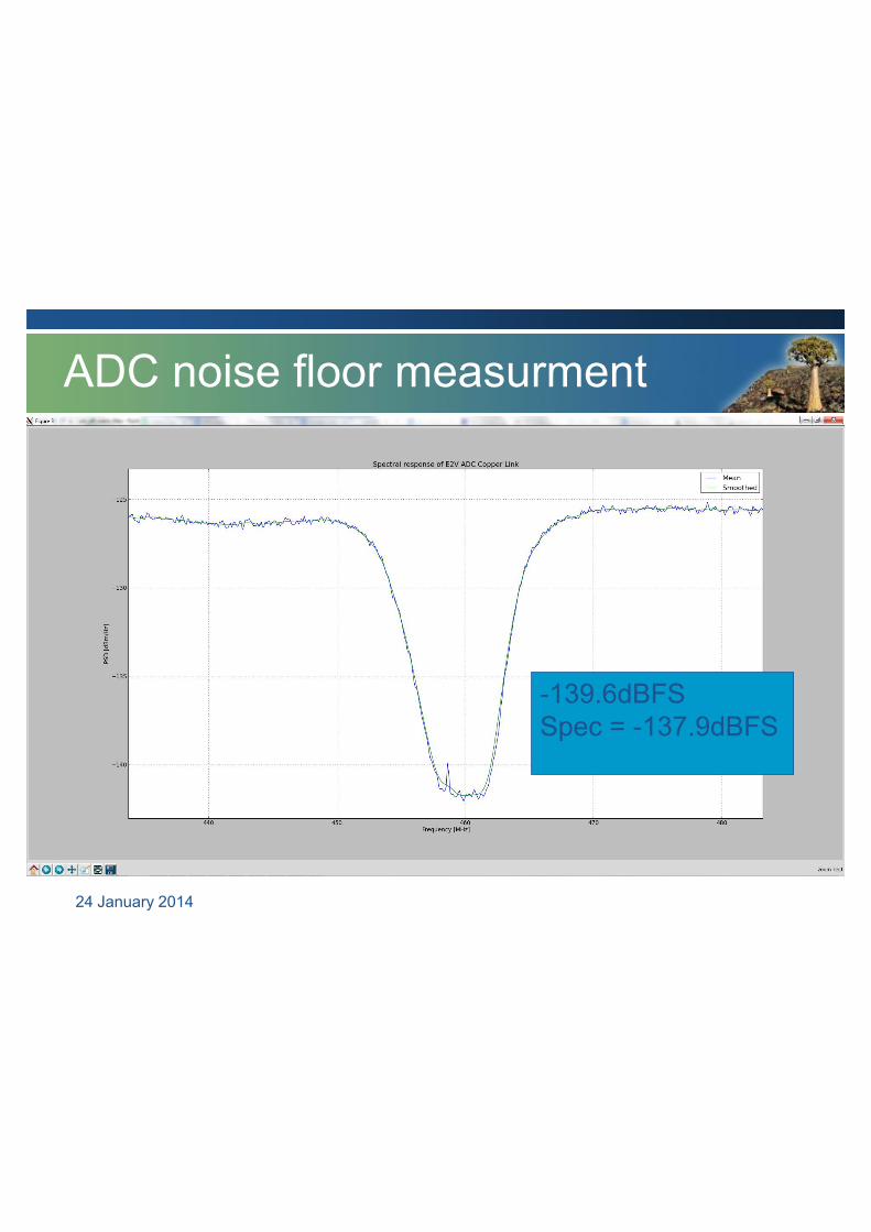
ADC noise floor measurment
24 January 2014
-139.6dBFS Spec = -137.9dBFS
MeerKAT Digitiser
Digitiser Sub-system
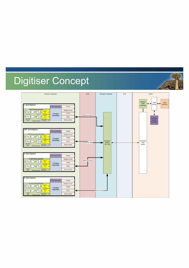
Digitiser Concept
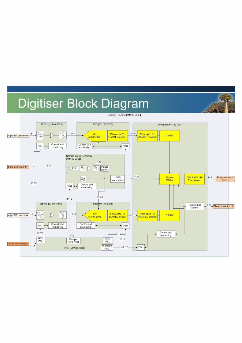
Digitiser Block Diagram
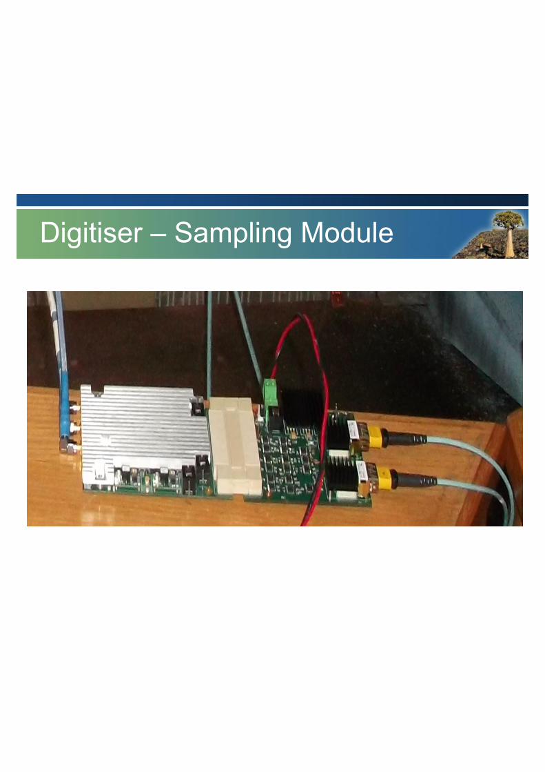
Digitiser – Sampling Module

Digitiser – “D-engine”
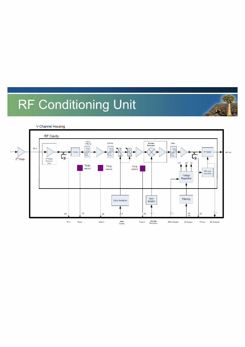
RF Conditioning Unit
Digitiser Key features
• Passband: 900 MHz – 1.67 GHz • Bandpass sampling (2nd Nyquist ) • 10 bits • 4 x 10 GbE output via SFP+ • 100dB shielded enclosure
• Likely re-used for UHF band with a modified
RFCU
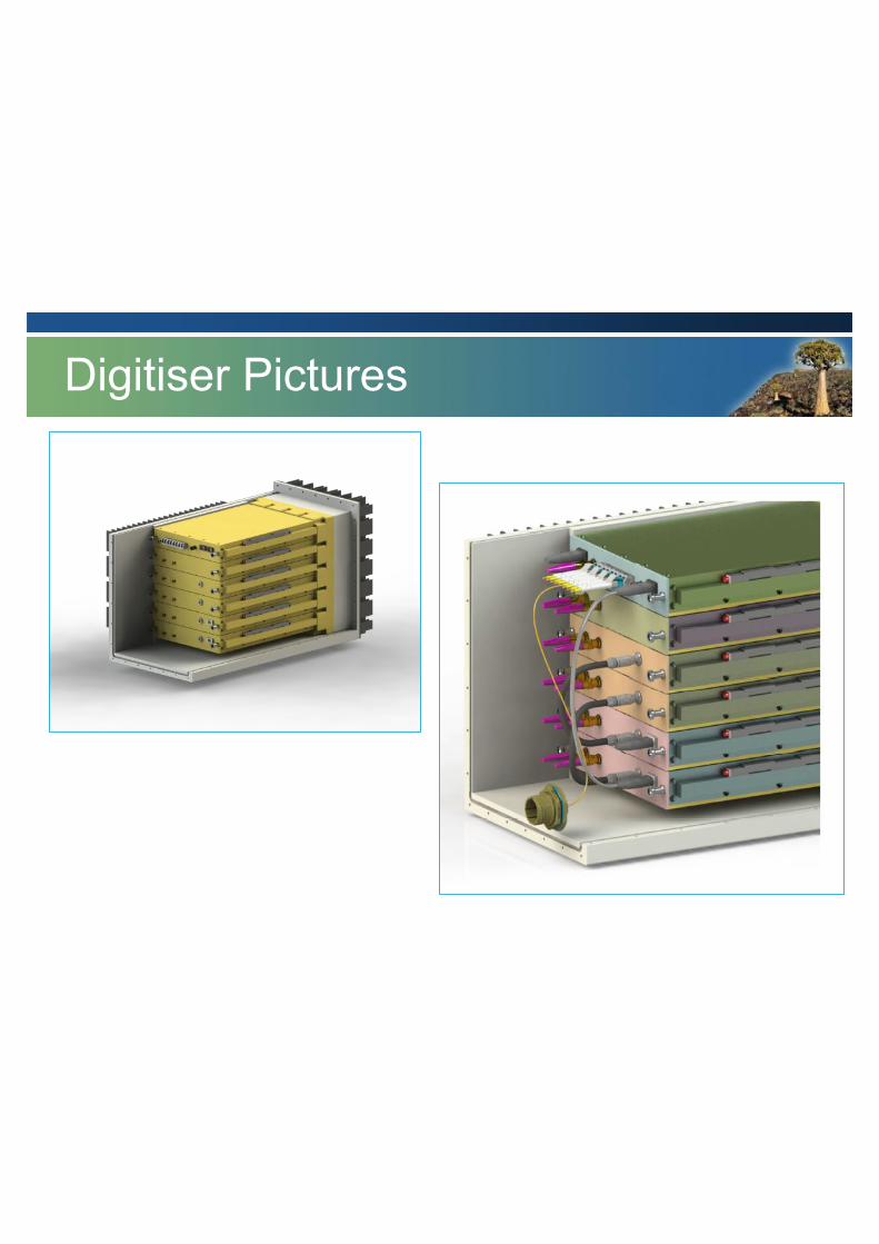
Digitiser Pictures
MeerKAT CBF
Correlator / Beamformer Sub-system
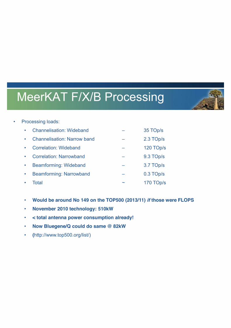
MeerKAT F/X/B Processing
• Processing loads:
• Channelisation: Wideband – 35 TOp/s
• Channelisation: Narrow band – 2.3 TOp/s
• Correlation: Wideband – 120 TOp/s
• Correlation: Narrowband – 9.3 TOp/s
• Beamforming: Wideband – 3.7 TOp/s
• Beamforming: Narrowband – 0.3 TOp/s
• Total ~ 170 TOp/s
• Would be around No 149 on the TOP500 (2013/11) if those were FLOPS
• November 2010 technology: 510kW
• < total antenna power consumption already!
• Now Bluegene/Q could do same @ 82kW
• (http://www.top500.org/list/)

MeerKAT Correlator Data Rates
For L-Band (856 MHz bandwidth)
• Input data rate ~ 2.3 Tbps
• Output data rates *
• Correlation (WB) ~ 175 Gbps
• Correlation (NB) ~ 55 Gbps
• Full Rate Beams (WB) ~ 55 Gbps
• Low Rate Beams ~ 137 Gbps
• Fly’s Eye (Single Dish) ~ 56 Gbps
• VLBI beams ~ 8 Gbps
• Antennae Voltage Buffer ~ 5 Gbps
• Incoherent Sum ~ 1 Gbps
* Not all simultaneously, hardware can be shared/reconfigured
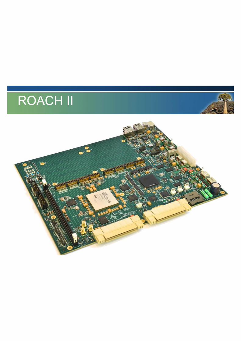
ROACH II

• (To be) Designed for MeerKAT Final Deployment
• Could work for SKA-1 F/X/B engines
• 28nm FPGA technology (?)
• 40 Gbps and 100Gbps Ethernet
• 20Gsps ADCs and faster
ROACH 3
>500 Produced
In Production
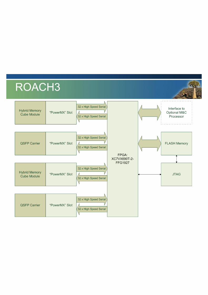
ROACH3
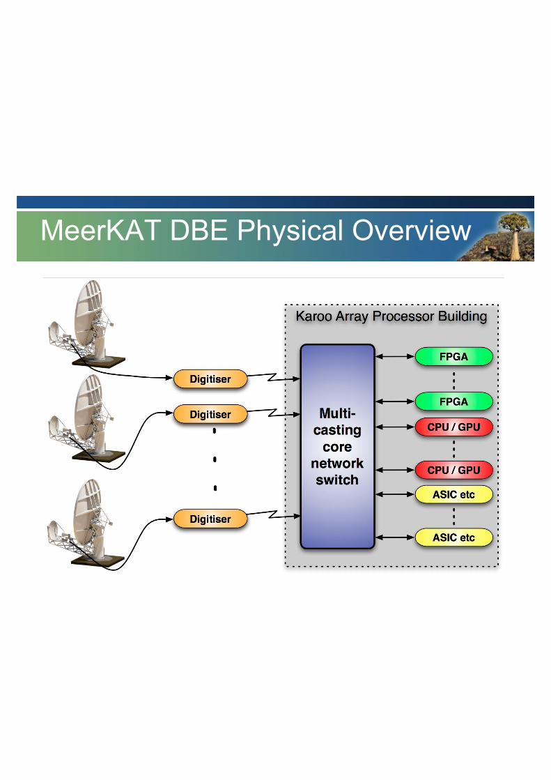
MeerKAT DBE Physical Overview
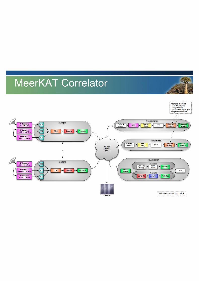
MeerKAT Correlator
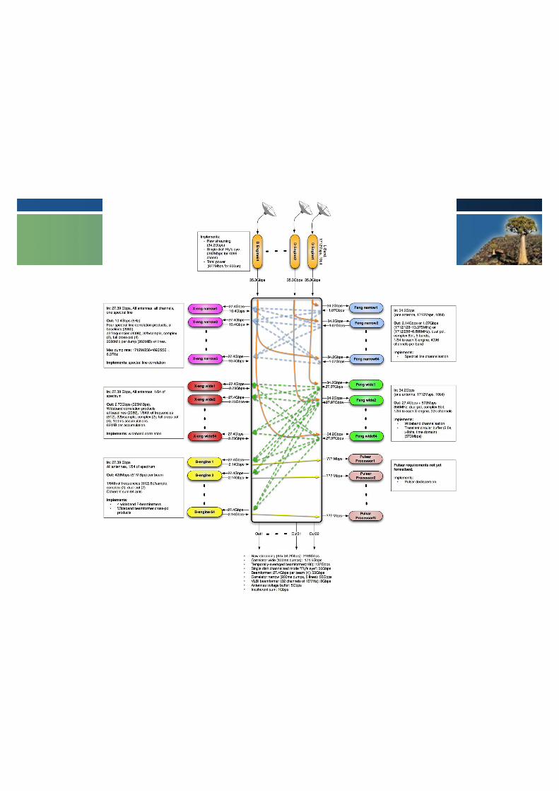

MeerKAT Data Flows
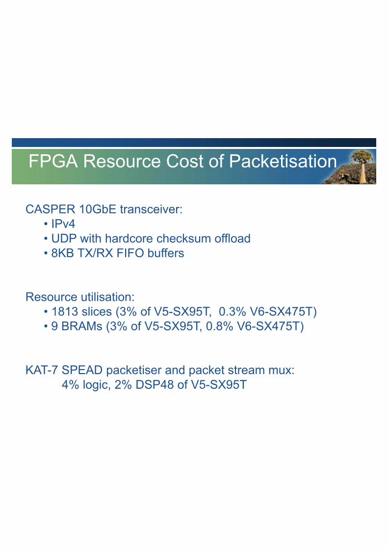
CASPER 10GbE transceiver: • IPv4 • UDP with hardcore checksum offload • 8KB TX/RX FIFO buffers
Resource utilisation: • 1813 slices (3% of V5-SX95T, 0.3% V6-SX475T) • 9 BRAMs (3% of V5-SX95T, 0.8% V6-SX475T)
KAT-7 SPEAD packetiser and packet stream mux: 4% logic, 2% DSP48 of V5-SX95T
FPGA Resource Cost of Packetisation
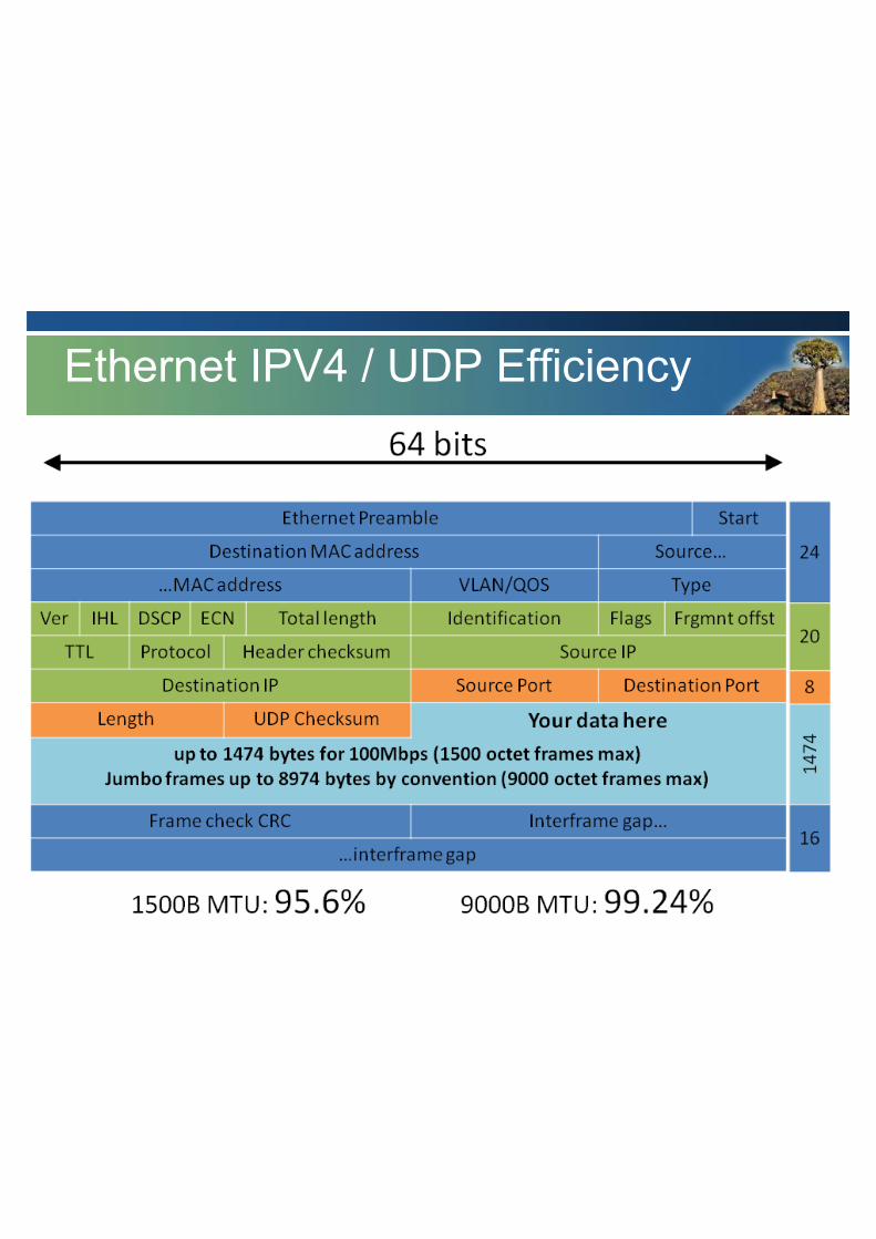
Ethernet IPV4 / UDP Efficiency
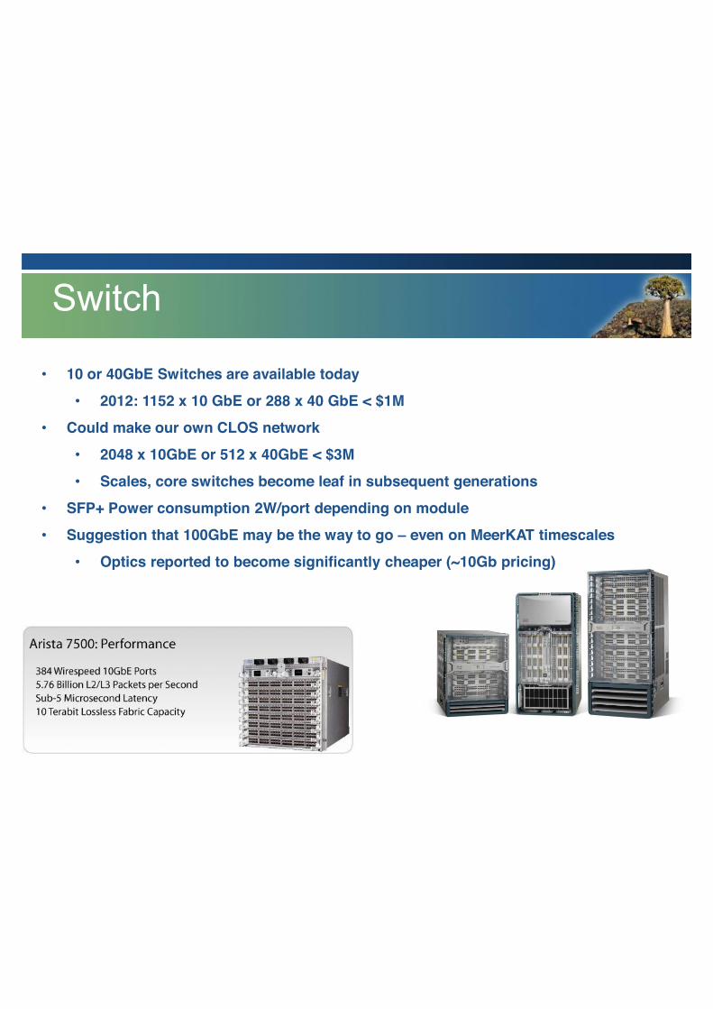
• 10 or 40GbE Switches are available today
• 2012: 1152 x 10 GbE or 288 x 40 GbE < $1M
• Could make our own CLOS network
• 2048 x 10GbE or 512 x 40GbE < $3M
• Scales, core switches become leaf in subsequent generations
• SFP+ Power consumption 2W/port depending on module
• Suggestion that 100GbE may be the way to go – even on MeerKAT timescales
• Optics reported to become significantly cheaper (~10Gb pricing)
Switch
• Likes:
• Multicasting support
• Cheap to implement – FPGA’s provide hard macros
• Resilient to errors
• Scalable and Flexible
• Interface to many divers technologies
• Simplified debugging and development
• Simplified Interfacing to adjacent systems
• Long lifetime, enables modular upgrade > 30yr compatibility lifetime
• Multiplexing and demultiplexing signal streams is trivial
• Dislikes:
• Inherent asynchronicity complicates FPGA development
• Some quirks to deal with (eg. Packet to self)
Packetised Interconnect: + / -
• HW is valuable, but short-lived
• SW and IP investment is much larger
• On-FPGA processors come and go – SW investment unpredictable
• Must enable re-use, across institutions, devices and generations (parameterisation)
• Turnkey solution required, enable designers to implement instruments
• Production yield must be considered
• Scaling limits must be eliminated
Some lessons learnt
• IO (many astronomy instruments are IO dominated)
• Unified Interconnect – both infra- and intra-board/chassis/rack
• Balanced Bandwidth – external IO and internal memory bandwidth matched
• Memory to Processing Ratio must be suitably high – both internal and external
• Prefer SRAM to DRAM
• Keep it simple! – 1 FPGA per board ROACH1/2/3
• Implement functions in hardware where possible
• Standalone operation is really useful – on-board processor is indispensible
• Allows development on/deployment of a single board
• Remote reboot/reload/hw management
• SW support system – think ecosystem
• Drag and drop functions – re-use
Digital Platform Wishlist
• Ethernet: flexible, scalable and cost-effective
• Common Digital Platforms: Have experience, lessons
learnt, successes!
• Shared DSP Libraries: Used on large instruments, but room for improvement
Conclusions
• Likes:
• Fantastic data oriented design language
• Rapid Application Development
• GUI environment
• Cross-platform (OS) support for development
• Configurable, parameterised, modular library
• Powerful MATLAB scripting environment
• Clock-cycle accurate simulations
• Tunable – can trade resources between DSP/Logic/BRAM
• Abstract away low-level functions
• Clocks
• HW/SW i/f’s
• One-click building
Collaboration: CASPER + / -
• Challenges:
• GUI based third party software changes are outside our control
• Vendor lock-in is hard to avoid, requires investment
• No effective multi-clock domain support
• Verification
• Library Maintenance
• Revision Control
• IP management – Open Source model may not be acceptable to all?
Collaboration: CASPER + / -