The medium access sublayer
69
THE MEDIUM ACCESS CONTROL SUBLAYER
-
Upload
lal-bahadur-gehlot -
Category
Education
-
view
2.279 -
download
0
Transcript of The medium access sublayer
THE MEDIUM ACCESS CONTROLSUBLAYER
• The protocols used to determine who goes next on a multi-access channel belong to a sublayer of the data link layer called the MAC (Medium Access Control) sublayer.
• The MAC sublayer is especially important in LANs, particularly wireless ones because wireless is naturally a broadcast channel.
• WANs, in contrast, use point-to-point links, except for satellite networks.
THE CHANNEL ALLOCATION PROBLEM• Static Channel Allocation• If there are N users, the bandwidth is divided into N
equal-sized portions, with each user being assigned one portion. Since each user has a private frequency band, there is now no interference among users.
• When there is only a small and constant number of users, each of which has a steady stream or a heavy load of traffic, this division is a simple and efficient allocation mechanism.
• A wireless example is FM radio stations. Each station gets a portion of the FM band and uses it most of the time to broadcast its signal.
• when the number of senders is large and varying or the traffic is suddenly changing(burst of data), FDM presents some problems.
• If the spectrum is cut up into N regions and fewer than N users are currently interested in communicating, a large piece of valuable spectrum will be wasted. And if more than N users want to communicate, some of them will be denied permission for lack of bandwidth, even if some of the users who have been assigned a frequency band hardly ever transmit or receive anything.

• A static allocation is a poor fit to most computer systems, in which data traffic is extremely bursty, often with peak traffic to mean traffic ratios of 1000:1. Consequently, most of the channels will be idle most of the time.

• The poor performance of static FDM can easily be seen with a simple queuing theory calculation. Let us start by finding the mean time delay, T, to send a frame onto a channel of capacity C bps.
• We assume that the frames arrive randomly with an average arrival rate of λ frames/sec, and that the frames vary in length with an average length of 1/μ bits. With these parameters, the service rate of the channel is μC frames/sec.
• A standard queueing theory result is• T = 1/(μC − λ)• Now let us divide the single channel into N independent
subchannels, each with capacity C /N bps. The mean input rate on each of the subchannels will now be λ/N. Recomputing T, we get
TN = 1/ (μ(C /N) − (λ/N)) = N/(μC − λ) = NT
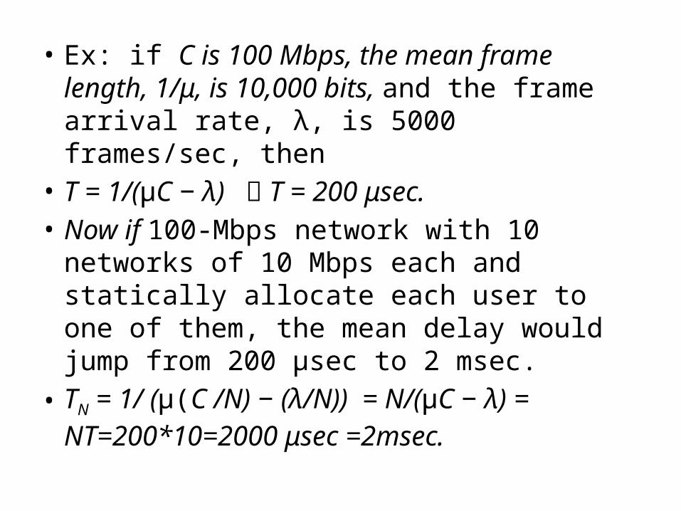
• Ex: if C is 100 Mbps, the mean frame length, 1/μ, is 10,000 bits, and the frame arrival rate, λ, is 5000 frames/sec, then
• T = 1/(μC − λ) T = 200 μsec.• Now if 100-Mbps network with 10 networks of
10 Mbps each and statically allocate each user to one of them, the mean delay would jump from 200 μsec to 2 msec.
• TN = 1/ (μ(C /N) − (λ/N)) = N/(μC − λ) = NT=200*10=2000 μsec =2msec.

• The mean delay for the divided channel is N times worse than that of without dividing. (TN = NT)
• This same result says that a bank lobby full of ATM machines is better off having a single queue feeding all the machines than a separate queue in front of each machine.

Assumptions for Dynamic Channel Allocation
• There are the following five key assumptions:• Independent Traffic• Single Channel.• Observable Collisions.• Continuous or Slotted Time.• Carrier Sense or No Carrier Sense

1. The model consists of N independent stations each with a program or user that generates frames for transmission. Once a frame has been generated, the station is blocked and does nothing until the frame has been successfully transmitted.
2. A single channel is available for all communication. All stations can transmit on it and all can receive from it.
3. All stations can detect that a collision has occurred. A collided frame must be transmitted again later.
4. Time may be assumed continuous, frame transmission can begin at any instant. Alternatively, time may be slotted or divided into discrete intervals (called slots). Frame transmissions must then begin at the start of a slot.
5. With the carrier sense assumption, stations can tell if the channel is in use before trying to use it. Station will transmit only when channel is free.

MULTIPLE ACCESS PROTOCOLSALOHA• Abramson’s work, called the ALOHA system,
used ground based radio broadcasting. The basic idea is applicable to any system in which uncoordinated users are competing for the use of a single shared channel.
• Two versions of ALOHA: pure and slotted. They differ w r t whether time is continuous, as in the pure version, or divided into discrete slots into which all frames must fit.(slotted aloha)

Pure ALOHA• In the ALOHA system, after each station has
sent its frame to the central computer, this computer rebroadcasts the frame to all of the stations. A sending station can thus listen for the broadcast from the hub to see if its frame has received properly.
• In other systems, such as wired LANs, the sender might be able to listen for collisions while transmitting.

• If the frame was destroyed, the sender just waits a random amount of time and sends it again. The waiting time must be random or the same frames will collide over and over, in lockstep.
• Systems in which multiple users share a common channel in a way that can lead to conflicts are known as contention systems.
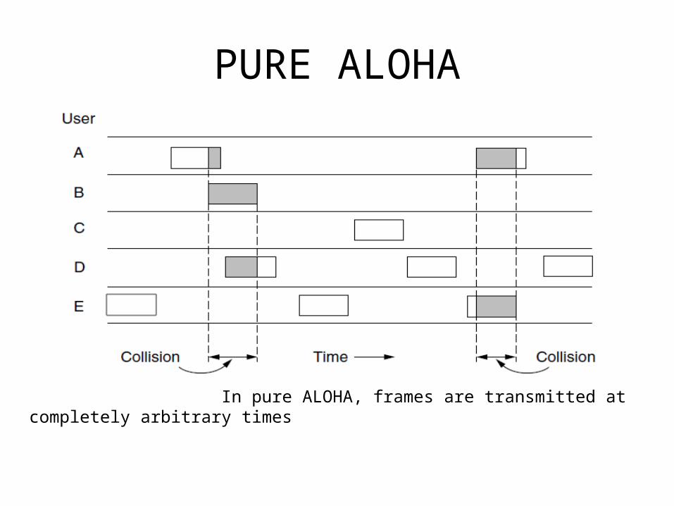
PURE ALOHA
In pure ALOHA, frames are transmitted at completely arbitrary times

• We have made the frames all the same length because the throughput of ALOHA systems is maximized by having a uniform frame size rather than by allowing variable-length frames.
• Whenever two frames try to occupy the channel at the same time, there will be a collision and both will be garbled. If the first bit of a new frame overlaps with just the last bit of a frame that has almost finished, both frames will be totally destroyed (i.e., have incorrect checksums) and both will have to be retransmitted later.
• The checksum does not (and should not) distinguish between a total loss and a near miss.
• Let the ‘‘frame time’’ denote the amount of time needed to transmit the standard, fixed-length frame (i.e., the frame length divided by the bit rate). At this point, we assume that the new frames generated by the stations are well modeled by a Poisson distribution with a mean of N frames per frame time. (The infinite population assumption is needed to ensure that N does not decrease as users become blocked.)
• If N > 1, the user community is generating frames at a higher rate than the channel can handle, and nearly every frame will suffer a collision. For reasonable throughput, we would expect 0 < N < 1.

• In addition to the new frames, the stations also generate retransmissions of frames that previously suffered collisions. Let us further assume that the old and new frames combined are well modeled by a Poisson distribution, with mean of G frames per frame time. Clearly, G ≥ N. At low load (i.e., N ∼ 0), there will be few collisions, hence few retransmissions, so G N. ∼
• At high load, there will be many collisions, so G > N.
• Under all loads, the throughput, S = GP0, where P0
is the probability that a frame does not suffer a collision.

Vulnerable period for the shaded frame.

• The probability that k frames are generated during a given frame time, in which G frames are expected, is given by the Poisson distribution Pr[k ] =Gk e−G /k!
• so the probability of zero frames is just e−G. In an interval two frame times long, the mean number of frames generated is 2G.
• The probability of no frames being initiated during the entire vulnerable period is thus given by P0 = e−2G. Using S = G P0, we get S = Ge−2G

Throughput versus offered traffic for ALOHA systems.

• The maximum throughput occurs at G = 0.5, with S = 1/2e, which is about 0.184. In other words, the best we can hope for is a channel utilization of 18%. This result is not very encouraging, but with everyone transmitting at will, we could hardly have expected a 100% success rate.

Slotted ALOHA• Divide time into discrete intervals called slots,
each interval corresponding to one frame.• A station is not permitted to send whenever the
user types a line. Instead, it is required to wait for the beginning of the next slot. Thus, the continuous time ALOHA is turned into a discrete time one.
• This halves the vulnerable period.(t instead of 2t)• The probability of no other traffic during the same
slot as our test frame is then P0 = e−G (instead of P0 = e−2G) and S = G P0 => S = Ge−G

• Slotted ALOHA peaks at G = 1, with a throughput of S = 1/e or about 0.368, twice that of pure ALOHA. The best we can hope for using slotted ALOHA is 37% of the slots empty, 37% successes, and 26% collisions.

Carrier Sense Multiple Access Protocols
• CSMA protocol was developed to overcome the problem found in ALOHA i.e. to minimize the chances of collision, so as to improve the performance.
• CSMA protocol is based on the principle of ‘carrier sense’. ("sense before transmit" or "listen before talk)
• The chances of collision can be reduce to great extent if a station senses the channel before trying to use it.
• Although CSMA can reduce the possibility of collision, but it cannot eliminate it completely. The chances of collision still exist because of propagation delay

• Protocols in which stations listen for a carrier (i.e., a transmission) and act accordingly are called carrier sense protocols.
• There are three different types of CSMA protocols :- (i) 1-Persistent CSMA (ii) Non-Persistent CSMA (iii) P-Persistent CSMA• Suppose the channel is currently busy(not free) then
Persistent protocol continuously listen the channel if it is free or not.(greedy approach) while nonresistant protocol will wait for a random amount of time before sensing the channel again.

• 1-Persistant CSMA• When a station has data to send, it first listens to
the channel to see if anyone else is transmitting at that moment.
• If the channel is idle, the stations sends its data. Otherwise, if the channel is busy, the station just waits until it becomes idle. Then the station transmits a frame.
• If a collision occurs, the station waits a random amount of time and starts all over again.
• The protocol is called 1-persistent because the station transmits with a probability of 1 when it finds the channel idle.

• Drawback of 1-persistent • Propagation delay: has an important effect on collisions. Let us
suppose, just after the station 1 begins its transmission, station 2 also become ready to send its data and sense the channel. If the station 1 signal has not yet reached station 2(due to propagation delay), station 2 will sense the channel to be idle and will begin its transmission. This will result in collision.
• This chance depends on the number of frames that fit on the channel, or the bandwidth-delay product of the channel. In most LANs since the propagation delay is small (low bandwidth delay product), the chance of a collision happening is small. The larger the bandwidth-delay product, collision increase and performance of the protocol decrease.
• Even if propagation delay time is zero, collision will still occur. If two stations become ready in the middle of third station’s transmission both stations will wait until the transmission of first station ends and both will begin their transmission exactly simultaneously. This will also result in collision.

• Non persistent CSMA: • A conscious attempt is made to be less greedy than
persistent. • A station that has a frame to send senses the channel.
If the channel is idle, it sense immediately.• If the channel is busy, it waits a random amount of
time and then senses the channel again.• In non-persistent CSMA the station does not
continuously sense the channel for purpose of capturing it when it defects the end of previous transmission .
• Consequently, this algorithm leads to better channel utilization but longer delays than 1-persistent CSMA.(no of collision reduced.)

Advantages of non-persistent• It reduces the chances of collision because the
stations wait a random amount of time before transmitting.
Disadvantages of non-persistent• It reduces the efficiency of network because
the channel remains idle when there may be stations with frames to send. This is due to the fact that the stations wait a random amount of time before transmitting.

• P-persistent CSMA: (prob. of transmission is p)• It applies to slotted channels such that the time
slot duration is equal to or greater than the maximum propagation delay time.
• When a station becomes ready to send, it senses the channel. If it is idle, it transmits with a probability p. With a probability q = 1 − p, it defers until the next slot.
• If that slot is also idle, it either transmits or defers again, with probabilities p and q. This process is repeated until either the frame has been transmitted or another station has begun transmitting.

• In the latter case, station acts as if there had been a collision (i.e., it waits a random time and starts again).
• If the station initially senses that the channel is busy, it waits until the next slot and applies the above algorithm.
• IEEE 802.11 uses refinement of p-persistent CSMA.
• Advt of P-persistant: reduce the chances of collision and improve the efficiency of the network. (for N station and p prob. Np < 1)

Persistent and Non persistent CSMA
Comparison of the channel utilization versus load for various random access protocols.

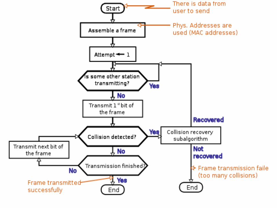
CSMA with Collision Detection• CSMA/CD is the basis of the classic Ethernet LAN. It is
important to realize that collision detection is an analog process.
• The station’s hardware must listen to the channel while it is transmitting. If the signal it reads back is different from the signal it is sending, it knows that a collision is occurring.
• The implications are that a received signal must not be tiny compared to the transmitted signal (which is difficult for wireless, as received signals may be 1,000,000 times weaker than transmitted signals) and that the modulation must be chosen to allow collisions to be detected.

• CSMA/CD consist of alternating contention and transmission periods, with idle periods occurring when all stations are quiet.
CSMA/CD can be in contention, transmission, or idle state.

A station cannot be sure that it has seized the channel until it has transmitted for 2τ without hearing a collision.(τ is propagation delay).
• Working of CSMA/CD:1. Is my frame ready for transmission? 2. Is medium idle? If not, wait until it becomes ready and start
transmitting.3. Did a collision occur? If so, Continue transmission of jam signal (The
jam signal is a signal that carries a 32-bit binary pattern sent by a data station to inform the other stations that they must not transmit. ) to ensure all other station detect collision.
Increment retransmission counter, wait for random back off (it refers to an algorithm used to space out repeated retransmissions of the same block of data, often as part of network congestion avoidance.)period based on number of collisions. Re-enter main procedure at stage 1.
4. If successful transmission, Reset retransmission counters and end frame transmission process.

Collision detected procedure
• Continue transmission (with a jam signal instead of frame header/data/CRC) until minimum packet time is reached to ensure that all receivers detect the collision.
• Increment retransmission counter.• Was the maximum number of transmission
attempts reached? If so, abort transmission.• Calculate and wait random backoff period based
on number of collisions.• Re-enter main procedure at stage 1.
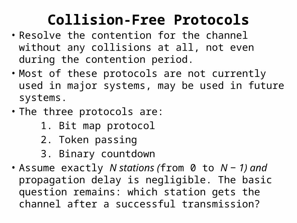
Collision-Free Protocols• Resolve the contention for the channel without any
collisions at all, not even during the contention period.• Most of these protocols are not currently used in major
systems, may be used in future systems. • The three protocols are: 1. Bit map protocol 2. Token passing 3. Binary countdown • Assume exactly N stations (from 0 to N − 1) and
propagation delay is negligible. The basic question remains: which station gets the channel after a successful transmission?
A Bit-Map Protocol
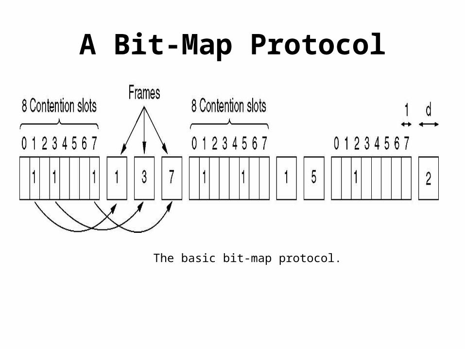
The basic bit-map protocol.
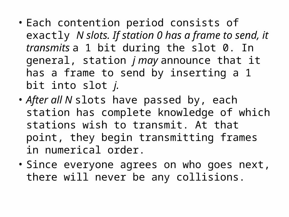
• Each contention period consists of exactly N slots. If station 0 has a frame to send, it transmits a 1 bit during the slot 0. In general, station j may announce that it has a frame to send by inserting a 1 bit into slot j.
• After all N slots have passed by, each station has complete knowledge of which stations wish to transmit. At that point, they begin transmitting frames in numerical order.
• Since everyone agrees on who goes next, there will never be any collisions.

• After the last ready station has transmitted its frame, an event all stations can easily monitor, another N-bit contention period is begun.
• If a station becomes ready just after its bit slot has passed by, it must remain silent until the bit map has come around again.
• Protocols like this in which the desire to transmit is broadcast before the actual transmission are called reservation protocols because they reserve channel ownership in advance and prevent collisions.

• The channel efficiency at low load is easy to compute. The overhead per frame is N bits and the amount of data is d bits, for an efficiency of d /(d + N).
• At high load, when all the stations have something to send all the time, the N bit contention period is prorated over N frames, yielding an overhead of only 1 bit per frame, or an efficiency of d /(d + 1).
• The mean delay for a frame is equal to the sum of the time it queues inside its station, plus an additional (N − 1)d + N time. This interval is how long it takes to wait for all other stations to have their turn sending a frame and another bitmap.

• Token Passing: pass a small message called a token from one station to the next in the same predefined order. The token represents permission to send.
• If a station has a frame for transmission when it receives the token, it can send that frame before it passes the token to the next station. If it has no queued frame, it simply passes the token.
• In a token ring protocol the topology of the network is used to define the order in which stations send.
• The stations are connected one to the next in a single ring. Passing the token to the next station then simply consists of receiving the token in from one direction and transmitting it out in the other direction. Frames are also transmitted in the direction of the token.

• No need for physical ring to implement token passing. The channel connecting the stations might instead be a single long bus. Each station then uses the bus to send the token to the next station in the predefined sequence. This protocol is called token bus.
• The performance of token passing is similar to that of the bit-map protocol.

Binary Countdown: • A problem with the basic bit-map protocol and token
passing is that the overhead is 1 bit per station, so it does not scale well to networks with thousands of stations.
• A station wanting to use the channel now broadcasts its address as a binary bit string, starting with the high order bit.
• All addresses are assumed to be the same length.• The bits in each address position from different stations
are BOOLEAN ORed together by the channel when they are sent at the same time. We will call this protocol binary countdown.
• It implicitly assumes that the transmission delays are negligible so that all stations see asserted bits essentially instantaneously.

• To avoid conflicts, an arbitration rule must be applied: as soon as a station sees that a high-order bit position that is 0 in its address has been overwritten with a 1, it gives up.
• After winning the bidding, a station may now transmit a frame, after which another bidding cycle starts.
• It has the property that higher- numbered stations have a higher priority than lower-numbered stations, which may be either good or bad, depending on the context.

Collision-Free Protocols
The binary countdown protocol. A dash indicates silence.

• The channel efficiency of this method is d /(d + log2N). If however, the frame format has been cleverly chosen so that the sender’s address is the first field in the frame, even these log2N bits are not wasted, and the efficiency is 100%.
• Binary countdown is an example of a simple, elegant, and efficient protocol.

IEEE STANDARDS
The 802 working groups. The important ones are marked with *. The ones marked with are hibernating. The one marked with † gave up.
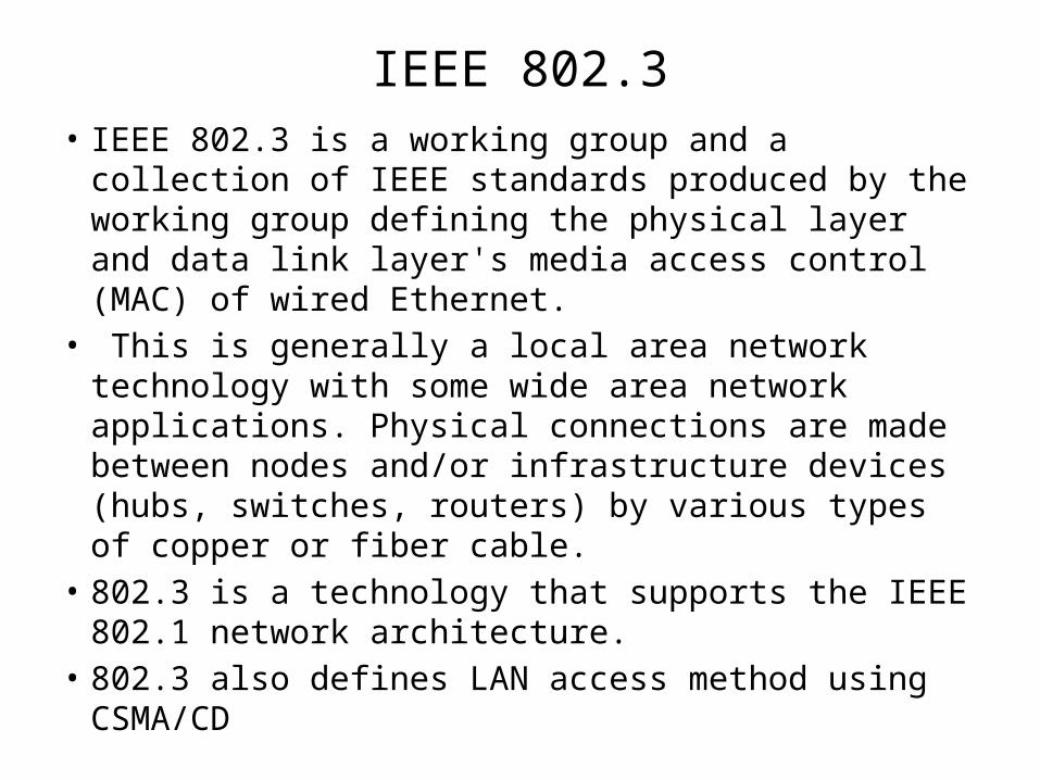
IEEE 802.3• IEEE 802.3 is a working group and a collection of IEEE
standards produced by the working group defining the physical layer and data link layer's media access control (MAC) of wired Ethernet.
• This is generally a local area network technology with some wide area network applications. Physical connections are made between nodes and/or infrastructure devices (hubs, switches, routers) by various types of copper or fiber cable.
• 802.3 is a technology that supports the IEEE 802.1 network architecture.
• 802.3 also defines LAN access method using CSMA/CD

IEEE 802.4• Token bus is a network implementing the token ring protocol over a
"virtual ring" on a coaxial cable.• A token is passed around the network nodes and only the node possessing
the token may transmit. If a node doesn't have anything to send, the token is passed on to the next node on the virtual ring. Each node must know the address of its neighbor in the ring, so a special protocol is needed to notify the other nodes of connections to, and disconnections from, the ring.
• Token bus was standardized by IEEE standard 802.4. It is mainly used for industrial applications. Token bus was used by General Motors for their Manufacturing Automation Protocol (MAP) standardization effort. This is an application of the concepts used in token ring networks. The main difference is that the endpoints of the bus do not meet to form a physical ring.
• Due to difficulties handling device failures and adding new stations to a network, token bus gained a reputation for being unreliable and difficult to upgrade.

IEEE 802.5• Token Ring is a LAN protocol defined in the IEEE 802.5 where all
stations are connected in a ring and each station can directly hear transmissions only from its immediate neighbor. Permission to transmit is granted by a message (token) that circulates around the ring.
• Token-passing networks move a small frame, called a token, around the network.
• Possession of the token grants the right to transmit. If a node receiving the token has no information to send, it seizes the token, alters 1 bit of the token, appends the information that it wants to transmit, and sends this information to the next station on the ring.
• While the information frame is circling the ring, no token is on the network, which means that other stations wanting to transmit must wait. Therefore, collisions cannot occur in Token Ring networks.

IEEE802.6• IEEE 802.6 is a standard governed by the ANSI for Metropolitan
Area Networks (MAN). It is an improvement of an older standard (also created by ANSI) which used the Fiber distributed data interface (FDDI) network structure.
• The FDDI-based standard failed due to its expensive implementation and lack of compatibility with current LAN standards. The IEEE 802.6 standard uses the Distributed Queue Dual Bus (DQDB) network form.
• This standard has also failed, mostly for the same reasons that the FDDI standard failed. Most MANs now use Synchronous Optical Network (SONET) or Asynchronous Transfer Mode (ATM) network designs, with recent designs using native Ethernet.

IEEE 802.11
• IEEE 802.11 is a set of medium access control (MAC) and physical layer (PHY) specifications for implementing wireless local area network (WLAN) computer communication in the 2.4, 3.6, 5 and 60 GHz frequency bands. They are created and maintained by the IEEE LAN/MAN Standards Committee (IEEE 802). These standards provide the basis for wireless network products using the Wi-Fi brand.

• IEEE 802.11 family consist of a series of half-duplex over-the-air modulation techniques that use the same basic protocol.
• The most popular are those defined by the 802.11b and 802.11g protocols, 802.11a was the first widely accepted one, followed by 802.11b and 802.11g. 802.11n is a new multi-streaming modulation technique.
• Other standards in the family (c–f, h, j) are service amendments and extensions or corrections to the previous specifications.

IEEE802.15• IEEE 802.15 is a working group of the Institute of Electrical
and Electronics Engineers (IEEE) IEEE 802 standards committee which specifies Wireless Personal Area Network (WPAN) standards. It includes seven task groups.
• 802.15.1 WPAN / Bluetooth• 802.15.2 Coexistence• 802.15.3 High Rate WPAN• 802.15.4 Low Rate WPAN• 802.15.5 mesh networking• 802.15.6 Body Area Networks• 802.15.7 visible light communication
IEEE 802.16
• The Workgroup is a unit of the IEEE 802 local area network and metropolitan area network standards committee.
• Although the 802.16 family of standards is officially called Wireless MAN in IEEE, it has been commercialized under the name “WiMAX” (from "Worldwide Interoperability for Microwave Access") by the WiMAX Forum industry alliance. The Forum promotes and certifies compatibility and interoperability of products based on the IEEE 802.16 standards.

Fiber Distributed Data Interface(FDDI)
• FDDI is a high performance fiber optic token ring LAN running at 100 Mbps over distance upto200km with up to 1000 station connected.
• It can be used in the same way as any of the 802 LANs , but with its high bandwidth, another common use is as a backbone to connect copper LANs.
• FDDI uses multimode fiber because the additional expense of single mode fibers is not needed for running at only 100 Mbps.
• It also uses LEDs rather than lasers ,not only due to their lower cost ,but also because FDDI may be used to connect directly to user workstations.
• FDDI design specification calls for no more than 1 error in 2.5 x1010 bits.
• FDDI cabling consists of two fiber rings, one transmitting clockwise and other transmitting counterclockwise.
• If either one breaks, the other can be used as a backup.

• FDDI define two classes of stations, A and B. class A stations connect to both rings. The cheaper class B stations only connect to one of the rings. Depending on how important fault tolerance is,an installation can choose class A or class B stations, or some of each.
• Basic FDDI protocols are closely modeled on the 802.5 protocols. To transmit data, a station must capture the token. then it transmit a frame and remove it when it comes around again.

DIFFERENCE• In 802.5 a station may not generate a new token
until its frame has gone all the way around and come back.
• In FDDI , with potentially 1000 stations and 200 km of fiber, the amount of time wasted waiting for the frame to circumnavigate the ring could be substantial.
• For this reason , it was decided to allow a station to put a new token back onto the ring as soon as it has finished transmitting its frame.
• In large ring, might be on ring at same time.

FDDI Frame Format
preamble Destination address Source address
data checksum
frame controlstart delimiter
Bytes >=8 2 or 6 2 or 6 No limit 4 1 1
Ending delimiterFrame Status
FDDI Frame Format
• The start delimiter and End delimiter fields mark the frame boundaries.
• The frame control field tells what kind of frame this is(data, control etc.)
• The frame status byte holds acknowledgement bits, similar to those of 802.5.
• FDDI also permits special synchronous frames for circuit- switched PCM or ISDN data.

• Once a station has acquired one or more time slots in synchronous frame, those slots are reserved for it until they are explicitly released.
• The total bandwidth not used by the synchronous frames is allocated on demand.
• A bit mask is present in each of these frames to indicate which slots are available for demand assignment.
• The non synchronous traffic is divided into priority classes , with the higher priorities getting first shot at left over bandwidth.

FDDI MAC protocol uses three timers. • Token holding timer- determine how long a
station may continue to transmit once it has acquired the token
• Token rotation timer- it is restarted every time the token is seen. If the timer expires, it means that the token has not been sighted for too long an interval. Probably it has been lost , so the token recovery procedure is initiated.
• Valid transmission timer – it is used to time out and recover from certain transient ring errors.

• Transmission time: A station takes some time to put the frame bits on to the channel. This is called the transmission time. (Ts=frame size/channel bandwidth)
• Ex: bandwidth 1Mbps frame size:10Kbyte. Ts=10*103*8/106 = 0.08sec=80ms
• Propagation time: Due to the length of wire, the bits moves from one end to another end with some delay (time to travel the distance), is known as propagation time(Tp). (distance/velocity of signal in wire)
• Ex: D=1000km and speed=2.4x10⁸ m/s Tp=1000*1000/2.4 x 108 = .00416sec=4.16ms

QUESTIONSQ1. A group of N stations share a 64-kbps pure ALOHA channel. Each
station outputs a 500-bit frame on average once every 100 sec, even if the previous one has not yet been sent .What is the maximum value of N?
Q2. Consider the delay of pure ALOHA versus slotted ALOHA at low load. Which one is less? Explain your answer.
1. With pure ALOHA the usable bandwidth is 0.184 × 64 kbps = 11.77 kbps.
Each station requires 5 bps (500 bits/100 sec), so N = 11770/5= 2354 stations.
2. With pure ALOHA, transmission can start instantly. At low load, no collisions are expected so the transmission is likely to be successful. With slotted ALOHA, it has to wait for the next slot. This introduces half a slot time of delay.

Q3. A large population of ALOHA users manages to generate 50 requests/sec, including both originals and retransmissions. Time is slotted in units of 40 msec.
(a) What is the chance of success on the first attempt?(b) What is the probability of exactly k collisions and then a
success?(c) What is the expected number of transmission attempts
needed?
3(a) With G = 2 (50*40/1000) the Poisson law gives a probability of e−2.
(b) (1 − e−G)k e−G ( 0.135 × 0.865k )(c) The expected number of transmissions is eG = 7.4.

END