
THE MECHANICAL PROPERTIES OF THE 18 PER … · of maraging steels (200,000 to 300,000-psi yield...
128
O o CO DMIC Report 198^^ F«burory 24, 1964 /Zf-S? ^,7 6- THE MECHANICAL PROPERTIES OF THE 18 PER CENT NICKEL MARAGING STEELS DIMNSE MiTALS INFORMATION CINTit Bott«IU Memorial Intfitut« Celvmbds I, Ohio D1 mi m
Transcript of THE MECHANICAL PROPERTIES OF THE 18 PER … · of maraging steels (200,000 to 300,000-psi yield...
O o CO
DMIC Report 198^^
F«burory 24, 1964
/Zf-S? ^,7 6-
THE MECHANICAL PROPERTIES OF
THE 18 PER CENT NICKEL MARAGING STEELS
■
DIMNSE MiTALS INFORMATION CINTit
Bott«IU Memorial Intfitut«
Celvmbds I, Ohio D1
mi m

'
Th« Defer»»« KleUli Information Center was eeUblishad at Battell« MemorUl Imtitut* at th« request of the Office of the Director of Defenae Research and Engineering to provide Govern- mont rontravitore end their euppliort technical asjlttance and information on titanium, beryllium, magneaium, aluminum, re« fractorymetale, high-etrengthalloys for higlv-temperature aervlce, corroaion- ard oxidation-re« intent coatings, and thermiUprotec- tion »ystenta. Its functione, under th« direction of the Office of the Director of Defense, are as follows:
1. To collect, store, «ad disseminate technical In- formation on the current status of research and development the above materials.
2. To supplement establlsbed Service activities in providing technical advisory services to pro- ducers, moltera, and fabricators of th« above materials, and tc designers and fabricators of military equipment containing thess material«.
3. To assist the Government agencies and their con- tractui-s in «Uvelopinf technical daia raqnired for preparation of specif)cations iar th« above ma» terlals.
4. Oa assignment, to conduct surveys, or laboratory research lavettigatloas, n ilaly of a short-range nat-irs, as required, to ascertain causes of trou- bles snccuntsr«d by fabricators, or to fill minor gap« In «atabllshed research programs.
Contract No. AF 33(615}-! 121 Project No. 8e S
Roger J. Runck
fro« may iBoaro«i, •»* «»•
tf4 tli» ueaal p?6lt»il»ry «kterial, andiAire copy-
^^. ^1 s^. Jli,

DMIC Report 198 February 24, 1964
THE MECHANICAL PROPERTIES OF THE 18 PER CENT NICKEL MARAGING STEELS
by
J. E. Campbell, F. J. Barone, and D. P. Moon
to
OFFICE OF THE DIRECTOR OF DEFENSE RESEARCH AND ENGINEERING
4, •
i <
&
DEFENSE METALS INFORMATION CENTER Battelle Mennorial Institute
Columbus 1,. Ohio

TABLE OF CONTENTS
*H1
SUMMARY 1
INTRODUCTION 3
EFFECTS OF ANNEALING AND AGING CONDITIONS, HARDENER CONTENT, AND COLD WORKING ON PFOPERTIES 4
Annealing and Aging Conditions 5 Ha'•dene r Content 10 Effect of Cold Working 13
TENSILE PROPERTIES 17
Effect of Section Size, Specimen Orientation, and Strain Rate 19 Effect of Melting Practice and Grain Size 22
COMPRESSIVE, SHEAR, BEARING, AND DYNAMIC MODULUS PROPERTIES .... 23
EFFECT OF TEMPERATURE ON THE SHORT-TIME MECHANICAL PROPERTIES . . 26
PROPERTIES OF NOTCHED SPECIMENS 32
Charpy Impact Properties 32 Notched Tensile Properties 35 Notched Bend Tests . 43
FATIGUE PROPERTIES 44
CREEP AND RUPTURE STRENGTH 54
PROPERTIES OF PRESSURE VESSELS OF MARAGING STEELS 54
REFERENCES 59
APPENDIX
PROPERTY DATA A-l
<
\

THE MECHANICAL PROPERTIES OF THE 18 PER CENT NICKEL MARAGING STEELS
SUMMARY
This report is intended to provide as complete a background of information on the mechanical properties of the 18 per cent nickel maraging steels as is obtainable at the present state of development of these alloys, "fcince the combination of tensile properties and toughness that can be obtained with the maraging steels is higher than can be achieved with other steels by simple heat treatments, there is considerable interest in using the maraging steels for critical components such as rocket motor cases, pressure vessels, and aircraft forgings. RrfciTTt thrnr nniif ffllny0 j0a" Kj> Ml—i4—l^JMI I—Ibap- li]jjl itiinii, i nnniriii-ahlr infrrmiitr-n on their m«rhanicai properties must be collected and gjuiUhitwi.
This report includes information on the tensile, compressive, shear, bearing, dynamic modulus, impact, bend, fatigue, creep, and rupture properties of the 18 per cent nickel maraging steels and on the effect of temperature on these properties. Data for the properties of sheet, bar, and forgings, as well as data illustrating the effect of cold rolling, variation in the heat treatment, and elevated-temperature exposure also are presented. Data on the effect of specimen orientation, which are also included, indicate that the ductility and toughness of specimens designed to evaluate the properties in the short transverse direction are somewhat lower than in the other directions.
The high strength and toughness that can be obtained in the 18 per cent nickel maraging steels make them attractive for certain critical applications that require these properties. The fabrication characteristics, weldability, and simple heat treatment are other advantages of these steels. (^TU—

INTRODUCTION
The maraging steels are a class of iron-nickel-cobalt-molybdenum-titaninm alloys with low carbon contents. There are four major types of maraging steels containing 15, 18, 20, and 25 per cent nickel. The 18 per cent nickel type is the most important at present because of its advantages for use in large high-strength structures including pressure vessels and large boosters. These advantages will become evident as the properties and processing of the 18 per cent nickel type are reviewed in this report.
'Within the 18 per cent nickel type, there are several grades arbitrarily based on yield strength; i.e. , the 200, 250, and 300 grades representing yield-strength levels of 200,000, 250,000, and 300,C')0p8i, respectively. In some instances, other grade des- ignations also have been used, e. g. , 180, 225, 280, and 325 grades. The actual strength level that may be achieved for a given heat of 18 per cent nickel maraging steel depends primarily on the "hardener content", that is, the amounts of titanium, molybdenum, and cobalt present in the alloy. Because of variations in the intended hardener content and "aging response", the actual properties obtained for a specified grade fall within a scat- ter band. The scatter bands for the various grades may overlap slightly, as is pointed out later.
The 18 per cent nickel maraging steels are hardened by a simple aging treatment. Water or oil quenching normally are not required after the annealing or aging treatments since these steels are martensitic (low carbon martensite) after slow cooling from the annealing temperature, which usually is 1500 F. Aging (maraging) in the range from 850 to 950 F promotes an age-hardening reaction. The actual mechanism of this reac- tion has not been determined although it is being studied.
Early in the development of these alloys, it was recognized that the nickel marag- ing steels had certain advantages over the low-alloy quenched-and-tempered martens- itic steels for many applications requiring high strength. These advantages include good forming characteristics of the annealed alloy even though it is martensitic, attainment of high strengths with a relatively simple heat treatment at moderate temperatures, minimum dimensional change and distortion on heat treatment, and virtual immunity to decarburization. Comparatively good weldability and good fracture toughness are also attributes of the maraging steels. Because of these attractive characteristics, and be- cause of the need for improved high-strength materials for aerospace applications in general and for large solid-propellant rocket-motor cases in particular, a considerable effort has been made in the past 2 years to develop and evaluate these new steels. The objectives of this effort have been to establish optimum compositions and melting and mill practices for the various commercial forms such as sheet, plate, bar, and forg- ings; to determine optimum forging, machining, welding, and heat-treating procedures; and to obtain a backlog of property data that can be used in specifications and designs for these steels.
In recent studies of the metallurgical properties of maraging steel plate, it has been observed that there is a tendency for this steel to develop a banded structure. This condition causes reduced short-transverse strength and ductility. Fractures in banded plate have shown that the dark-etching portion of the banded structure has lower strength than the lighter etching portion. These studies are being continued to try to minimize the effect of banding.

In several instances, cracks have developed at welds in thick sections of maraging steels. Even though this report is not primarily concerned with the properties of welded joints, the problem is mentioned in the interest of caution. In addition, it should be noted that the maraging steels are considerably more expensive than the low-alloy mar- tensitic steels. Consequently, use of the maraging steels is generally limited to special high-strength componeits for which the cost can be justified.
A preliminary review of the properties of the nickel maraging steels was presented by the Defense Metels Information Center in Memorandum 156 dated July 2, 1962. Since then, a large number of reports containing data on the maraging steels have reached DMIC. This report is a summary and review of the data presented in these other reports.
The data presented in this memorandum are limited to the 18 per cent nickel types of maraging steels (200,000 to 300,000-psi yield strengths) since most current interest in the maraging steels is in the 18 per cent nickel compositions. The composition ranges for these grades are as followsO*^)*:
Alloying Element^
Ni
Grade (200) (250) (300)
17-19% 17-19% 18-19% Co 8.0-9.0 7.0-8.5 8.5-9.5 Mo 3.0-3.5 4.6-5.2 4.6-5.2 Ti 0. 15-0.25 0.3-0.5 0.5-0.8 Al 0.05-0. 15 0.05-0. 15 0.05-0. 15
(a) Other elements (per cent): 0.03 maximum C, 0.10 maximum Mn, 0.10 maximum Si, 0.01 maximum S. and 0.01 maximum P. Other elements added (per cent): 0.003B, 0.002Zr, and 0.05Ca.
EFFECTS OF ANNEALING AND AGING CONDITIONS, HARDENER CONTENT, AND COLD WORKING ON PROPERTIES
In all of the 18 per cent nickel grades of maraging steel, transformation to mar- ten site occurs above room temperature on cooling from the hot-working or the annealing temperatures. Typical tensile properties and hardness values for bar stock annealed 1 hour at 1500 F and air cooled are as follows'1):
(250) Grade, (300) Grade, air melted vacuum melted
Yield Strength, 95,000 110,000 0. 2 per cent offset, psi
Tensile Strength, psi Elongation in 1 Inch, per cent Reduction in Area, per cent Hardness, Rockwell C
140,000 150,000 17 18 75 72
28-30 30-32
♦References appear at the end of the report.

Since final strengthening is achieved by an aging treatment, variations in annealing and aging conditions have been studied in a number of programs in order to determine the preferred treatments for optimum properties. Variations in composition and effects of cold working on the mechanical properties also have been evaluated as discussed in the following sections.
The aging response of these alloys whether wrought or cast is affected by such factors as hardener content (titanium, molybdenum and cobalt) and by prior treatment (melting and casting procedures, hot working, warm working, cold working, and anneal- ing processes). Effects of some of these factors are discussed. It should be emphasized that since these factors can cause variations in the properties, careful control of all of the processing procedures is required to obtain consistent properties from one heat to the next.
Annealing and Aging Conditions
As a result of the studies of annealing cycles for wrought 18 per cent nickel mar- aging steels, the recommended annealing treatment is usually 1 hour at 1500 F followed by air cooling. This cycle apparently results in optimum ductility since specimens an- nealed at lower or higher temperatures have lower values for reduction in area. This is shown in Figure l(3). The 1-hour treatment at 1500 f is the most frequently used an- nealing cycle for all of the wrought grades of 18 per cent nickel maraging steel. For plate and forgings over 1 inch in thickness, the annealing treatment is often 1 hour at 1500 F per inch of thickness.
Aging of wrought products without annealing also will result in substantial strength- ening. This effect is shown in Table 1 for 1/2-inch plate of 18Ni (250) naraging steel in the hot-rolled-and-aged condition and in the annealed-and-aged condition. The annealed- and-aged specimens normally have slightly higher and more uniform properties than the hot-rolled-and-aged specimens. Therefore, for best control of properties, the anneal- and-age treatment is preferred. This same effect pertains to all grades of 18 per cent nickel maraging steels'^).
The effects of variations in aging temperature and in time at temperature are also shown in Table 1. The best balance of strength and ductility is usually obtained by aging at about 900 F for 3 or 4 hours after annealing at 1500 F. Figures 2 and 3 show values for yield strength for transverse and longitudinal specimens aged at 850, 900, and 950 F for 1,3, and 10 hours and illustrate the typical aging response for these alloys. For some heats, longitudinal specimens have higher strengths than the transverse specimens as in Table 1. For others, the transverse specimens are stronger as in Figures Zc c 3. This probably depends on the degree of cross rolling.
For cast 18 per cent nickel maraging steels, a preliminary treatment at 2100 F has been used to obtain higher properties than can be achieved with only the 1500 F an- nealing treatment. The improvement in properties resulting from the 2100 F treatment is shown in Table 2.

290
2 270
I 260
230
00
50
40
^ 30
20
10
I3C0
Elongation
T ± 1400 1500 1600
Solution - Treating Temperature, F
1700
A-46149
FIGURE 1. EFFECT OF SOLUTION-TREATING TEMPERATURE ON THE LONGITUDINAL PROPERTIES OF 18NI (250) MARAGING STEELO)
Solution treating time — 1 hour. Aged at 900 F for 3 hours. Heat 23832; 0.01C, 0. (/14Kfn, 0. 003P, 0. 002S, 0.04Si, 18. 60Ni, 5.04Mo, 7. 74Co, 0. 08A1, 0.42Ti, O.OOICa, 0. 003Zr, 0.002B.

TABLE 1. TENSILE PROPERTIES OF AIR-MELTED 1/2-INCH PLATE OF 18Ni (250) MARAGING STEEL AS HOT ROLLED AND AGED AND AS ANNEALED AND AGED(4)
Aging Yield Treatment Strength
0. 2% Offset, Tensile
Strength, Elongation in 1 Inch,
Reduction Terrp, Time, in Area,
F hours Direction 1000 psi 1000 psi per cent per cent
Hot Rolled and Aged
850 L 252 263 9.0 39.6 850 L 260 272 8.6 38.9
900 L 265 273 7.6 37.2 900 T 243 255 9.5 40.7 900 L 283 289 7.1 38.6 900 8 T 263 272 8.0 42.9
950 L 264 272 7.7 38.5 950 L 266 276 7.6 39.2
5 Annealed at 1500 F for 30 Minutes and AKed
850 L 258 266 9.1 47.0 850 L 268 276 8.8 46.5 850 16 L 284 291 7.7 42.1 850 16 T 264 276 8.1 42.4
900 4 L 275 281 7.9 43.5 900 4 T 259 268 8.8 46.7 900 8 L 286 292 7.6 40.3 900 8 T 273 279 7.5 42.9
950 2 L 261 267 8.9 46.5 950 4 L 269 278 7.9 41.6
Note: Tests made on 1/4-inch-diameter specimens. Composition of Heat 13371: 0,023C, 0.003P, 0.009S, O.C6Si, 18.65Ni, 8.05Co. 4.90MO, 0.52Ti, 0. 05A1.

8
300
850 900
Aging Temperature, F 950
A-45098
FIGURE 2. EFFECT OF AGING TREATMENT ON THE YIELD STRENGTH OF 0. 115-INCH-THICK 18Ni (250) MARAGING STEEL SHEET^3'5)
Composition: 0. 010C, 0. 014Mn, 0. 003P, 0. 002S, 0. 04Si, 18.60Ni, 5.04Mo, 7.74Co, 0.42Ti, 0. 08A1.
Specimens annealed at 1500 F for 1 hour and air cooled before aging.

320
850 900
Aging Temperature, F 950
A-49096
FIGURE 3. EFFECT OF AGING TREATMENT ON THE YIELD STRENGTH OF 0.115-INCH-THICK 18Ni (300) MARAGING STEEL SHEET(3,5)
Composition: 0.008C, O.OlSMn, 0.001P, 0. 003S, 0. 05Si, 18.6lNi, S.OOMo, 9.05Co, 0.71Ti, 0. 13A1.
Specimens annealed at 1500 F for 1 hour and air cooled before aging.

10
TABLE 2. EFFECT OF ANNEALING TREATMENT ON THE ROOM-TEMPERATURE TENSILE PROPERTIES OF CAST 18Ni (250) MARAGING STEEL(6)
Annealing Treatment
Temp, F
Time, hours
Yield Strength 0. 2% Offset,
1000 psi
Tensile Strength, 1000 psi
Elongation, per cent
Reduction in Area, per cent
Hardness, Rockwell C
1500
2100 1500
2100
5} 253
262
254
274
275
270
1.7
5.8
5.7
3.2
21.0
20.2
51
52
51-52
Note: All specimens aged at 900 F for 3 hours after the annealing treatment. Heat 06990-1: 0.03C, 0.14Si, <0.10Mn, <0.01S, <0.01P, 4.74Mo, 18.32NI, 9.33Co, 0.45Ti, 0.12A1, 0.0035B, <0.01Zr.
Hardener Content
The effects of hardener content have been assessed by various investigators. International Nickel Company investigators have estimated that, within the composition range of the 18 per cent nickel maraging steels, the incremental effect of cobalt on the yield strength is 1000 psi for each 0. 1 per cent added, for molybdenum it is 2000 psi for each 0. 1 per cent added, and for titanium it is 10,000 psi for each 0. 1 per cent.* The results of another investigation^7) indicate that 0. 1 per cent increments of the alloying elements increase the yield strength the following amounts: cobalt, 1200 psi; molybde- num, 2800 psi; and titanium, 6000 psi. Other investigators have suggested an empirical equation relating hardener content to the strength obtained on aging, as plotted in Figure 4.
The equation
Yield Strength (1000 psi) « 15. 1 + 9. 1(% Co) + 28. 3(% Mo) + 80. 1(% Ti)
has also been proposed^4). When this equation is used to estimate the range in yield strength that is possible considering the limited ranges of hardener contents in the spec- ification for one grade, the yield strengths may vary by as much as 35,000 psi. This indicates the need for conducting aging-response studies on each heat to be certain of the actual properties that can be achieved and to permit matching the properties of all the individual components for each fabricated item.
Although some variation is reported in the actual magnitude of the effect of each of the hardening elements, it is apparent that titanium has the greatest influence on the strength of the maraging steels, as aged. The effect of titanium content on the yield strength of the 250 and the 300 grades of 18 per cent nickel maraging steels is shown in Figures 5 and 6. The data from which these curves were plotted are presented in
'R. F. Decker, private communication.

11
330
320 i o o 5 310
300
2 290
c 21 ^•
</>
>
2 280 'Si c
270
260
Ä 'A i It /
./ Y L ■ 1 //
f
6 ^ / %<¥ ■
• /x j/ /•
\j
■ 5^ ■ I..._ A
i i
Longitudinal — c © "■— o
■ Transverse [ i i i 1
31 32 33 34 35 36 37 38 Hardener Content, % Co M x % Mo +10 x% Ti A45097
FIGURE 4. EFFECT OF ALLOY CONTENT ON THE YIELD STRENGTH OF 0. 062-INCH-THICK 18Ni (300) MARAGING STEEL SHEET ANNEALED AT 1500 F FOR 1 HOUR AND AGED AT 900 F FOR 3 HOURS(8)
340
300
260
a> £ 220
180
Production Heats • I500F-Ihr +900F-3hr A 1500 F-30 min +900F-2hr Laboratory Heats
lo 1500 F-anneal+ 900 Faae
A6939«
1 A7035» X5I623 ^ ̂
846
23664#
06137^ 25»,
^/A6824
AX5I742
4UUb9
Heat n data p
jmbers show oints.
i beside
0.2 0.4 0.6 Titanium Content, per cent
08 A-45098
FIGURE 5. EFFECT OF TITANIUM CONTENT ON THE YIELD STRENGTH OF 18Ni (250) MARAGING STEEL
Both production size and laboratory heats are shown. (5) Compositions of heats are given in Table A-1 in the Appendix.

12
CL
330
320
310
300
C 290 0) w ♦- tn TJ 280 1 > 0) 270
| h- 260
250
M|
y k \/
o
A /
•
y 0 4 . /
/
A X
• i
/
1 ■ •1 »2/
V i
X Trans verse 1 1
\0.060 sheef J c
4
> Longitudinal J 9.0 Co, 5.0 Mo |
k Transverse \0.030 sheet 4 »Long i*jdina 1 18.4-9,6 Co,
4.7 - 5.3-Mo i 1 1
2 0.3 0.4 0.5 0.6 0.7 0.8 0.9 1.0 I.I Titanium Content, per cent A-45097
FIGURE 6. EFFECT OF TITANIUM CONTENT ON THE YIELD STRENGTH OF 18Ni (300) MARAGING STEEL ANNEALED AT 1500 F AND AGED AT 900 F FOR 3 HOURS(7,9)
See Tables A-2, A-3, and A-4 in the Appendix for compositions and properties.

13
Tables A-l through A-4 in the Appendix. The data points in Figures 5 and 6 show that the titanium must be on the high side of the ranges usually specified (0. 3 to 0. 5 for the 250 grade and 0. 5 to 0. 8 for the 300 grade) if the expected yield strengths are to be attained. The variations in properties at a given titanium level are undoubtedly attribut- able to numerous factors including variations in the contents of the other two hardener elements, cobalt and molybdenum.
Effect of Cold Working
A number of investigations are in progress on the effects of cold working on the properties of maragi .g steels. Some of the data that have been accumulated are pre- sented in Figures 7 and 8 and listed in Tables A-5 through A-8 in the Appendix. These data show that the strengths of both the 250 and the 300 grades of 18 per cent nickel mar- aging steel, as aged, are increased bv prior cold working. Also, cold working tends to decrease sli- . 'y the time and temperature at which maximum strength is achieved dur- ing aging. These data led to the conclusion that the maximum yield strength was obtained when the rretd was cold worked 50 per cent before aging, and that the optimum aging time at 900 F was I. 75 hours for the 250 grade and 5. 4 hours for the 300 grade.
The effects of cold working on the tensile properties of bar stock are shown in Table 3.0°)
TABLE 3. EFFECT OF COLD WORKING ON THE TENSILE PROPERTIES OF 18Ni{250) MARAGING STEEL BAR ST0CK(10)
0. 2% Offset Cold Work, Yield Strength,
per cent 1000 psi
Tensile Strength, 1000 psi
Elongation in 1 Inch, per cent
Reduction in Area, per cent
0 261 25 272 50 293
264 277 298
8.6 6.5 5.2
57 49 44
Note: Aged at 900 F for 3 hours after cold working. Specimens 1/4-inch diameter.
CoiJ working also affects the elastic modulus of maraging steels as shown by dy- namic modulus tests.' ' The variation in modulus is not only dependent on the heat- treating and cold-working cycles but also on the orientation of the specimen, as shown in Table 4 for sheet of 18Ni(250) maraging steel in several different conditions.
In highly stressed structures that require joining of various components by welding or other means, it may be advisable to match the modulus of adjoining components so the deformations under load will be as uniform as possible.
The effect of cold working on Poisson's ratio for 18Ni(250) maraging steel sheet are shown in Table 5 [tentative data by Kula(12)]. Young's modulus was 26 x 10^ psi for each condition.

340
a Aged at 900 F
340
30 40 00 Cold Work t per cent
b. Aged at 850 F
70 A-49100
FIGURE 7. EFFECT OF COLD WORKING, AGING TIME, AND AGING TEMPERATURE ON THE LONGITUDINAL YIELD STRENGTH OF 18Ni (250) MARAGING STEEL(3)
Composition: 0. 010C, O.OUMn, 0. C03P, 0. 002S, 0.04Si, 18.60Ni, 5.04Mo, 7.74Co, 0.42Ti, 0. 08A1.

15
I 350
330
$ 310
I ■ I- 290
... r.,_ 10 hours^*<
^
i ^ 3 hours
5
( 4 vr. ;
1 hour ^>k
-
a. Aged at 900 F
350
330
ij: £ o> 310 c
1 TJ 0) 290 >
1 c 1 2 70
250 10
3 hours >'
'Y r
r I hour
20
^4
30 40 50 60 70 Cold Work,percent A-45I0I
b. Aged at 850 F
FIGURE 8. EFFECT OF COLD WORKING, AGING TIME, AND AGING TEMPERATURE ON THE LONGITUDINAL YIELD STRENGTH OF 18Ni (300) MARAGING STEEL<3)
Composition: 0. 008C, 0.015Mn, 0.001P, 0. 003S, 0.05Si, 18.6lNi, S.OOMo, 9.05Co, 0.71Ti, 0. 13A1.

16
TABLE 4. EFFECT OF COLD WORKING AND ORIENTATION ON THE DYNAMIC MODULUS^11)
Condition
Dynamic Modulus^ IQDpsi Longitudinal Transverse Specimens Specimens
As received annealed at 1500 F for 15 min 25.8 27.6
Aged at 900 F for 3 hours
As-received material cold worked 60%
Cold worked 60% and aged at 900 F for 3 hours
27.3
26. 1
27.8
29.2
29.4
30.9
Cold worked 60%, annealed 1500 F for 1 hour, and aged at 900 F for 3 hours
Reannealed 1500 F for 1 hour, cold worked 60%, and aged 900 F for 3 hours
27.3
27.2
28. 1
30.6
Note: See Figure 10 for composition.
TABLE 5. EFFECT OF COLD WORKING ON POISSON'S RATIO
Direction Cold Work,
per cent Pois son's
Ratio
0. 31 0. 28 0. 26 0. 31 0. 31 0. 26
L L L T T T
0 40 60
0 20 60
Note: Data obtained on tensile loading sheet ipecimens which were annealed at 1500 F, cold worked, and aged at 900 F for S hours. Composition: Heat C. 0.U2C, O.lOSi. O.OSMn. 0.009S. O.OOSP. l8.96Ni. 7.34Co. 5.04MO. 0.05A1, 0.29Ti, 0.004B. O.OlZr. O.OSCa.

17
The strain-hardening exponent, n, obtained on specimens from 1 -inch plate having a yield ttrength of 230,000 psi and tensile strength of 240,000 psi was 0. 039. O)
Ausforming experiments at Llockheed(^) on specimens of 18Ni (300) maraging steel did not yield any improvement in mechanical properties. The specimens were cooled from 1500 F to 900 F or 450 F and strained about 25 per cent, cooled to room temperature, then to -100 F, and finally aged at 900 F for 3 hours.
The data presented here are only indicative of the considerable amount of data that have been accumulated on the effects of warm and cold working these steels. Much of the research being done on the effects of cold working involves the lower alloy grades of the 18 per cent nickel maraging steels.
TENSILE PROPERTIES
Data on the room-temperature tensile properties of the various grades of 18 per cent nickel maraging steels, collected from numerous sources, show the influence of form (section size), melting practice, and testing direction on the tensile properties. These data can be conveniently grouped and presented according to three mill forms:
(1) Sheet in thicknesses up to 0. 25 inch
(2) Plate, in thicknesses from 0. 25 to 2. 5 inches
(3) Heavy sections including rounds, bars, slabs, billets, forgings, and squares.
Melting practices represented by these data include air melting, air melting with vac- uum degassing, and vacuum-arc remelting.
The tensile data collected in this section represent only one condition of heat treatment: solution annealing at 1500 F followed by aging at 900 F for 3 or 4 hours. Tensile data are listed in Tables A-9 through A-17 in the Appendix. Each data point is an average of data from two or more tesc specimens. From these data, the minimum, maximum, and overall average tensile properties were determined and tabulated in Table A-18. The data in Table A-18 help to illustrate the scatter in tensile properties. Table A-18 also includes the number of tct points used for computing the average val- ues. This provides some indication of the significance of the overall average values reported.
The effects of section size, melting practice, and testing direction on tensile prop- erties are shown in Figure 9, which is a bar graph of the average tensile properties (tensile strength, yield strength, and elongation) of the (200), (250), and (300) grades of the 18 per cent nickel maraging steels. It is obvious from the bar graph that the average yield strengths of all the 18Ni (200) grade forms lie well above the 200,000-psi yield- strength line and that average yield strengths of over 230,000 psi have been obtained within this grade of steel. The average yield strength levels for the I8Ni (250) grade usually lie just above the 250,000-psi yield-strength line. It appears that average yield strengths of 250,000 psi can be consistently obtained and that yield st engths up to 270,000 psi have been obtained with this grade. The da^a for the 18Ni (300) grade

i i
r-1200)
Gra
de -i
(250
) G
rade
(3
00)
Gra
de
-,
Lege
nd
□ L
-long
itudi
nal
E3
T-tr
ansv
erse
S
T-sh
ort t
rans
vers
e A
M-a
ir m
elt
VA
R-v
acuu
m a
rc
rem
elt
VD
-vac
uum
de
gass
ed
TS-te
nsile
stre
ngth
Y
S-t
ensi
le y
ield
st
reng
th
Not
e-a
11 sp
ecim
ens
solu
tion
anne
aled
at
1500
F,
aged
900
F
for
3 or
4 h
ours
_
— 2
c ■
12 &
10 s
8
"5
o»
c
o
UJ
oo
>
A-4
6150
S
hee
FIG
UR
E 9
. A
VE
RA
GE T
EN
SIL
E P
RO
PE
RT
IES
OF T
H3
18N
i M
AR
AG
ING S
TE
EL
S (2
00,
250,
AN
D 3
00 G
RA
DE
S)
FO
R V
AR
IOU
S F
OR
MS, M
EL
TIN
G P
RA
CT
ICE
S,
AN
D T
EST
ING D
IRE
CT
ION
S

'''''' .... i i i I—I .r. J ■ . . ' . i II wi I |
19
materials, in all forms, clearly indicate that average yield strengths for this grade are usually near the 280,000-poi level.
Considering the data for all the grades of maraging steels suggests several gen- eralizations. The spread between the average tensile-strength and yield-strength val- ues within each grade is fairly constant and overall averages about 8,000 psi. The ductility of the steels varies with the strength levels and the type of product. As the tensile strengths increase the ductility tends to decrease, while the ductility of sheet tends to be less than that of the other forms. The elongations reported are for a 1-inch gage length in most instances. For all the maraging steel grades, the average elonga- tion ranged from 3 per cent to 12 per cent.
Effect of Section Size, Specimen Orientation, and Strain Rate
The bar graph in Figure 9 also indicates that section size generally does not influ- ence the strength level that can be achieved for a given composition. In other words, the hardening reaction is not limited by section size for the 18 per cent nickel maraging steels as it is in the case of the quench-hardening low-alloy martensitic steels.
An example of the effect of section size on the tensile properties of a forging of 18 per cent nickel maraging steel is shown in Table 6. Specimens taken from a 4-inch- thick section had the same strengths as those from a section U. 62 inch thick. However, the ductility of the specimens taken from the transverse and short transverse directions in the thick section was lower than that for the longitudinal specimens and for the trans- verse specimens from the thinner web section. The ductility is dependent on the amount of hot working and on the direction of specimen orientation.
TABLE 6. AVERAGE TENSILE PROPERTIES OF 18Ni (250) MARAGING STEEL FORGING AT HEAVY AND THIN SECTIONS(14,
Location(a' Direction
Yield Strength 0. 2% Offset,
1000 psi
Tensile Strength, 1000 psi
Elongation in 1 Inch, per cent
Reduction in Area, per cent
Heavy Section
Web Section
Long. Trans. ST
Long. Tians.
251 250 252
254 251
263 262 264
266 263
10.0 4.5 4.8
10.5 10.0
47.4 14.2 23.9
53.2 48.1
Note: Heat W-G 10081, vacuum-arc remelted, 0.020C, 0.16Si. 0.03Mn. 0.006S, O.OOSP, 18.16Ni. 4.40Mo. 7.22CO. 0.54Ti, 0.22A1. Heat treatment, 1500 F 1 hour, air cooled, aged 900 F 3 hours. ST - short transverse,
(a) Heavy section was 4 inches thick; web section was 0.62 inch thick.

20
Tensile data on specimens from a 40-inch-diameter from: dome forging for the Pershing missile motor case further illustrate the effect of specimen orientationO^);
Yield Strength, psi Tensile Strength, psi Elongation in 1 Inch, per cent Reduction in Area, per cent
Radial and Tangential Directions
278,000-286,000 289,600-297,000
6.5-10.0 34. 1-48.2
Short Transverse Direction (Average)
279,100 288,600
4.3 16.5
These specimens were annealed 1 hour at 1500 F, air cooled and aged at 900 F for 3 hours. The tensile and yield strengths fall within relatively narrow bands but the duc- tility is substantially lower for specimens taken from the short transverse direction than from the other directions. These data also indicate that the ductility is influenced by the degree of hot working.
Typical tensile properties from the longitudinal and transverse directions for sheet and plate of 18 per cent nickel maraging steel are shown in Table 7. It is assumed that the longitudinal direction is the same as the direction of the final rolling passes. Obviously, there is little if any difference in the longitudinal and transverse directions in the sheet and plate from these heats. Apparently the degree of cross rolling was ade ■ quate to overcome any differences that might be detected by unnotched tensile tests.
TABLE 7. EFFECT OF ORIENTATION ON THE TENSILE PROPERTIES OF 18 PER CENT NICKEL MARAGING STEEL SHEET AND PLATE
Yield Strength Thickness, 0. 2% Offset,
inch Direction 1000 psi
Tensile Elongation Strength, in 2 Inches, 1000 psi per cent Heat Reference
••
0.075
0.075
0.065
0.50
Long. Trans.
230 233
237 242
7.8 7.5
24285 (VAR)(a)
Long. Trans.
266 271
274 278
7.2 6.8
W-24178 (VAR)(a)
Long. Trans.
251 257
264 268
7.0 6.8
06498 (VAR)(a)
Long. Trans.
248 244
255 250
13 12
X-13371 (Air melt)
15
16
Note: Aging treatment: 900 F 3 hours, (a) Vacuum-arc remelt.
In evaluating the tensile properties of sheet and plate using full-thickness speci- mens, the thickness of the material has a marked effect on the elongation as shown in Table 8. These data show a definite trend in thickness versus elongation from 0. 025 to 0. 250-inch thickness for the (250) and (300) grades. This effect; should be considered Ariien setting up specifications for these alloys. The data in Table 8 also show the effect of gage length in measuring the elongation. The elongation in a 1-inch gage length is

21
TABLE 8. TENSILE PROPERTIES OF TRANSVERSE SPECIMENS OF 18 PER CENT NICKEL MARAGING STEEL SHEET AND PLATE OF VARIOUS THICKNESSESO7)
Yield Strength 0. 2% Offset,
Tensile Strength,
£1« angation Thickness, In 1 Inch, In 2 Inches,
inch 1000 psi 1000 psi per cent per cent
(250) Grade
0.025 274 280 2.0 1.0 0.040 268 269 3.0 1.5 0.050 274 276 4.5 2.0 0.062 262 268 5.0 2.5 0.075 284 289 6.0 3.0 0.090 261 264 6.0 3.0 0.125 264 279 7.0 3.5 0.187 252 264 6.0 3.0 0.250 274 278 9.0 4.5 0.375 272 275 12.0 6.0 0.500 266 268 10.0 5.0 0.750 263 266
(300) Grade
10. 0 5.0
0.025 294 300 2.0 1.0 0.040 293 302 3.5 2.0 0.050 299 300 4.5 2.5 0.062 303 318 5.0 2.5 0.075 305 306 6.0 3.0 C. 087 309 310 6.0 3.0 0.098 308 309 6.5 3.5 0.125 291 299 6.5 3.5 0.190 276 290 7.5 4.0 0.250 295 304 10.0 5.0 0.500 276 284 9.0 4.5
Note: All specimens were vacuum-arc remelted material solution annealed for 1 hour per inch of thickness and air cooled. Each specimen was aged for 3 hours at 900 F. Data are averages for two specimens.

twice that in a 2-inch gage length (when measured on the same specimen) . This is characteristic of materials that develop little or no uniform elongation before necking occurs during tensile testing. It is also characteristic of materials that have yield strengths only slightly lower than the ultimate strengths.
Only limited data are available on the effect of strain rate on the tensile properties of the 18 per cent nickel maraging steels. However, results of tests at 0. 005, 0. 05, and 0. 102 inch per inch per minute on one series of specimens from bar stock of (300) grade indicated that there was a slight increase in tensile and yield strengths for both longitudinal and transverse specimens within this range of strain rates. l"*l Data ob- tained by other investigatorsO^) on three sets of specimens of 18Ni (300) sheet aged at 900 F for 3 hours and tested at 0. 005 inch per inch per minute and at crosshead speeds of 1 inch and 2 inches per minute also indicate that this alloy is not strain-rate sensitive within this range.
Effect of Melting Practice and Grain Size
From the bar graph in Figure 9, there does not appear to be a consistent differ- ence in tensile properties attributable to melting practice. This is further illustrated by the tensile data presented in Table 9 for 0. 5-inch-thick plate from five heats of 18 per cent nickel maraging steel made by air melting, by air melting plus vacuum degassing, and by vacuum arc remelting. The differences in properties can be more easily attrib- uted to variations in composition rather than melting practice.
TABLE 9. TENSILE PROPERTIES OF 0. 5-INCH-THICK PLATE Of 18 PER CENT NICKEL MARAGING STEEL PRODUCED BY DIFFERENT MELTING PRACTICES^4)
1 ' Yield Strength Tensile Elongation Reduction Melting 0.2% Offset, Strength, in 1 Inch, in Area,
Heat Practice Direction 1000 psi 1000 psi per cent per cent
13371 Air melted Long. 274.7 280.8 7.9 43.5 Trans. 259.3 267.7 8.8 46.7
120D163 Air melted + Long. 257.8 269.6 9.5 45.9 vacuum degassed Trans. 271.0 279.7 8.8 41.4
3888472 Vacuum-arc Long. 277.5 287.7 9.7 42.0 remelted Trans. 273.7 283.0 9.0 40.5
3888473 Vacuum-arc Long. 277.4 286.5 8.2 38.6 remelted Trans. 282. 1 293.4 8.8 39.3
07148 Vacuum-arc Long. 291.7 300.8 , 7.5 39.6 remelted Trans. 291.5 301.0 7.2 36.7
Note: Heat treatment: 1500 F 30 minutes, air cooled, 900 F 4 hour*. Compositions:
Heat 13371 120D163 3888472 3888473
C 0.023 0.016 0.019 0.020
Mn
0.J25 0.03
P 0.003 0.005 0.006 0.005
S 0.009 0.003 0.003 0.003
SI 0.06 0.18 0.08 0.07
Ni 18.65 18.60 18.60 18.80
Co 8.05 8.00 9.10 8.82
Mo 4.90 4.95 5.10 4.85
Tl 0.52 0.48 0.62 0.65
Al 0.05 0.06 0.07 0.07
07148 0.018 0.03 0.006 0.003 0.09 18.70 9.30 5.12 0.65 0.39

23
The effect of melting practice is examined also in later sections from the view- point of notched properties and fatigue properties.
While investigating the cause for low ductility in a 4 by 4-3/4-inch 18Ni (300) bil- let, it was found that the grain size of the billet ranged from Grain Size No. 2 near the surface to No. 5-6 at the center'1°). Results of tensile tests on specimens taken from various locations in the billet indicated that the grain size had a marked effect on the ductility. The data were as follows:
Grain Size No. 2 2-3 3-4 4-5 5-7 Elongation, per cent 0 4. 4 6.3 6.9 6.3 Reduction in Area, per cent 19.6 29.9 31.5 35.8 40.3
The tensile strength was 288,000 to 294,000 psi and the yield strength was 276,000 to 284,000 psi for the specimens from all the locations. It appears therefore that varia- tions in the grain size have little if any effect on the unnotched tensile strength and yield strength but that these variations do have a marked effect on the ductility. Since the grain size is largely dependent on the degree of hot working and the finishing tempera- ture, one objective in forging and hot rolling operations is to finish at as low a tempera- ture as practical in the hot-working range consistent with the required reductions.
COMPRESSIVE, SHEAR, BEARING, AND DYNAMIC MODULUS PROPERTIES
As shown in Tables 10 and 11, only a few data for compressive, shear, and bear- ing strength properties for the maraging steels are available and these correspond to specific tensile-strength levels. In order to estimate the strength parameters at other tensile-strength levels, the data have been nondimensionalized by dividing each strength value by the corresponding tensile ultimate or yield strength. Corresponding values for AISI 4340 steel heat treated to a minimum tensile strength of 260,000 psi are included in these tables for comparison. A reasonably close relationship between the corre- sponding ratios for these two types of steel appears to exist.
Dynamic modulus data have been obtained on one heat of 18Ni (250) maraging steel sheet 1/8 inch thick in various orientations. H ') The sheet was mill annealed at 1500 F for 1 hour and cooled in air. Data for specimens that were reannealed at 1500 F for 15 minutes, then aged at 900 F for 0. 5, 1.5, and 3 hours, are shown graphically in Fig- ure 10. The various aging times and specimen orientations (as well as aging tempera- tures and amounts of cold working which were discussed previously) have marked effects on the modulus values. These variations in modulus may represent a problem to de- signers in planning large welded structures in which uniform elastic deformation is de- sired. Nonuniform elastic deformation in two pieces joined by a weld will cause in- creased stresses at the weld.
~-4.

24
TABLE 10. ROOM-TEMPERATURE STRENGTH RATIOS FOR COMPRESSIVE AND SHEAR STRENGTHS OF 18 PER CENT NICKEL MARAGING STEELS AGED AT 900 F FOR 3 HOURS AND FOR AISI 4340 STEEL AT 260,000-PSI TENSILE STRENGTH
.
Form Grade Dlxectlon Compreuive Yield Strength, psi
Tenille Yield Strength, psi Shear Strength, psi
Teruile Strength, pti Heat Reference
Sheet
Sheet
Plate
(250)
(250/aJ
(260)
Bar. 1/4" D (260)
Bar. 1/4" D (300)
Bar (300)
Bar (300)
AISI 4340 —
247,000 252,000
0.98
886.000,, if 289. 000
247,000 230,000
1.07
24M22.1.09 228,000
287.000 272.000
1.06
288.000. 1M
272,000
1.12' (b)
143,000 262,000
0.56
143 000 . 0 .60
240 000
143 000, 0 61 236 000
149 000 0 56
264 000
167. 000,, 0. 55 302. 000
163. 000 „ 0. 58 281. 000
162. 000 ^ 0. S8 282, 000
0.57(b)
23832
06989
19
1. 20
10
1Ü
21
07081 18. 21
(a) This heat has been designated as (250) grade but its properties are more like the (300) grade. (b) Ratios for AISI 4340 steel, heat treated to 260,000-p$i minimum tensile strength, MIL-HDBK-ö. "Strength of Metal
Aircraft Elements". March, 1961.
TABLE 11. ROOM-TEMPERATURE STRENGTH RATIOS FOR BEARING STRENGTHS OF 18NI (300) MARAGING STEEL BAR AGED AT 900 r FOR 3 HOURS AND FOR AISI 4340 STEEL AT 260.000-PSI TENSILE STRENGTH
Bearing Strength (e/D ■ 1.5), psi Tensile Strength, psi
Bearing Strength ^e/D ■ 2), psi Tensile Strength, psi
Bearing Yield Strength (e/D "1.6), psi Tensile Yield Strength, psi
Bearing Yield Strength (e/D ■ 2), psi Tensile Yield Strength, psi
References
He at: 06989
39L 281
000 000
1.39
500, 000 281, 000 1.78
382, 000 1.40 272. 000
474. 000 „ 1.7K
07081
272,000
21
402 282
000 000 1. 43
513,000^ 282.000
1 .82
372 272,
000 ^ 000
1 .37
431, ooo a 1 .58 272,000
21
AISI 4340 Steel
1.33
1.69
1.44
1.69
MIL-HDBK-5
.

25
Orientation, degrees from rolling direction A-46i9i
FIGURE 10. EFFECT OF SPECIMEN ORIENTATION AND AGING TIME ON DYNAMIC MODULUS OF 18Ni (250) MARAGING STEEL SHEET
Specimens reannealed at 1500 F for 15 minutes, then aged at 900 F for 1/2, 1-1/2, and 3 hours. Tensile properties in transverse direction: 250,000 to 264,000 psi yield strength, 278,000psi tensile strength, and 4.5 to 5.5 per cent elongation in 1 inch. Composition: 0. 02C, 0. 21Si, 0. OlMn, 0. 007S, 0. 006P, 18. 45Ni, 4.65Mo, 7. 55Co, 0. 51Ti, 0. 07A1.

26
EFFECT OF TEMPERATURE ON THE SHORT-TIME MECHANICAL PROPERTIES
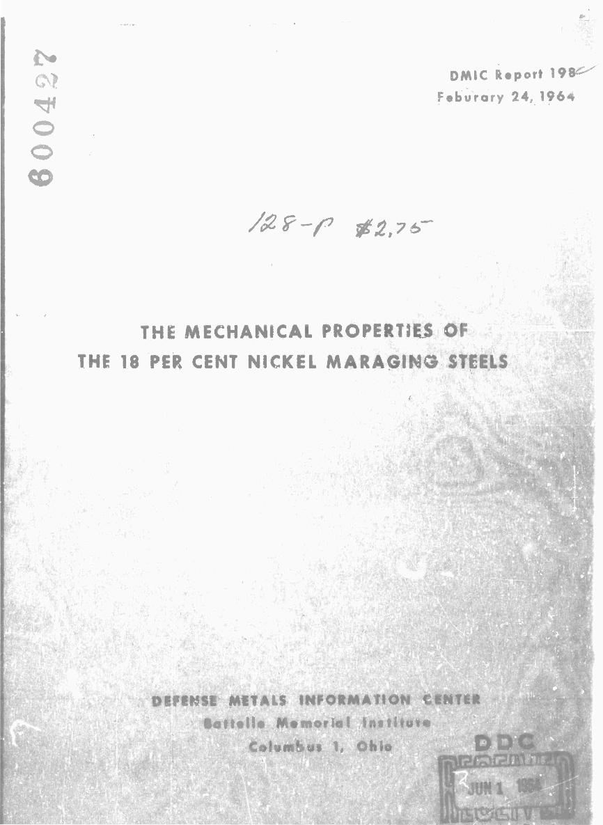
Studies of the mechanical proper* i'-J of the 18 por cent nickel maraging steels at cryogenic and elevated temperatures have indicated that their usefulness is not limited to ambient-temperature applications. Typical tensile properties at cryogenic tempera- tures for the 18Ni (250) alloy are shown in Figure 11. "*) As for most other engineering alloys, the strength increases as the testing temperature is decreased below room tem- perature. The ductility and impact properties tend to decrease as the temperature is decreased. The maraging steels do not have the corrosion resistance (as do stainless steels, aluminum, and titanium alloys) that is usually desired for cryogenic applica- tions, but they might be considered for certain applications to -320 F.
The elevated-temperature properties of the maraging steels have b-jen determined by a number of investigators and those at the INCO Laboratories have developed a modi- fied composition with improved properties to 1000 F. The modification in composition, as well as use of an 1800 F annealing temperature, are intended to raise the austenite reversion temperature — that is, to increase the stability of the martensite. Elevated- temperature tensile properties of the improved alloy containing 15. 2 per cent nickel and an alloy within the 18Ni (300) type composition are shown in Table 12. It will be seen that these alloys have interesting properties for service in the range from room tem- perature to 1000 F. At 1000 F, only a small amount of surface scale forms on these alloys in an air atmosphere(22).
TABLE 12. EFFECT OF TEMPERATURE ON THE TENSILE PROPERTIES OF MARAGING STEEL AS 3/4-INCH-DIAMETER
BAR STOCK
Heat Heat Treatment
Ten Temp,
F
Yield Strength. 1000 psl
Tensile Strength, 1000 ptl
Elongation, per cent
Reduction in Area, per cent Reference
32(a)
06461 (b)
1800 F. air cool. 70 281 300 6 23 900 F, 3 hr 300 251 272 8 32
500 235 259 9 40 800 218 241 10 41 900 205 231 12 49
1000 186 203 16 60
1600 F, air cool. RT 286 293 11 52 900 F. 3 hr 600 230 245 11 51
900 200 217 16 59
22
23
(a) Heat 32 (induction melted): 15.2Ni, 9.2Co, 5. IMo, 0.70Ti (composition for use at elevated temperatures). (b) Heat 06461 (vacuum-arc remelted) 18.77Ni, 8.98Co, 4.88Mo, 0.77Ti.
Additional data on the effect of temperature on the short-time mechanical proper- ties of the wrought 18 per cent nickel maraging steels are recorded in Tables A-19 to A-23 in the Appendix. Since the variation which prevails in room-temperacure tensile properties has been covered earlier in this report, room-temperature properties are duplicated in these tables only to the extent that they serve as a reference bas«. for prop- erties at elevated and cryogenic temperatures and for miscellaneous mechanical prop- erties at room temperature. In most cases, the values listed are averages of several test points. An attempt has been made to include all of the pertinent information that was available in preparing these tables.
27
-250 -200 -150 -100
Test Temperatur», C A • 46152
FIGURE 11. TENSILE AND IMPACT PROPERTIES OF 18Ni (250) MARAGING STEEL PLATE AT CRYOGENIC TEMPERATURES [ 1/2-INCH PLATE, HEAT A, KULA(12)]
Composition: 0.02C, 0. 09Si, 0. 07Mn, 0. 009S, 0. 004P, 18. 39Ni, 7.83Co, 4.82Mo, 0. 07AI, 0. 35Ti.

28
In preparing design data for inclusion in MIL.-HDBK-5, "Strength of Metal Air- craft Elements", and-similar documents, it has been found that short-time elevated- temperature strength data are most easily handled on a nondimensional basis. That is, each data point is represented as a percentage of the corresponding room-temperature value. In this manner, elevated-temperature data that exhibit some degree of scatter on a dimensional basis can often be reduced to a smooth curve for which scatter is within the range of that normally attributed to variations in testing techniques.
Proceeding in this manner, ultimate-tensile-strength and tensile-yield-strength values from Tables A-19 and A-20 in the Appendix were nondimensionalized and are plotted in Figures 12 and 13. In preparing these figures, it was found that the mean curves drawn through all data points fit equally well for the steels of the 18Ni (250) and 18Ni (300) grades. To use these figures to estimate the strength of a specific lot of 18 per cent nickel maraging steel at some specified temperature, it is only necessary to read the percentage value from the mean curve at that temperature and multiply the room-temperature strength of the material by that percentage.
Elevated-temperature tensile properties for one heat of cast 18Ni (250) maraging steel are presented in Table A-21 in the Appendix. The strengths of the cast alloy at the elevated temperatures are comparable with those of the wrought product but the duc- tility tends to be a little lower.
Bearing-ultimate- and bearing-yield-strength data points from Table A-23 were considered too few to justify drawing an effect-of-temperaturo curve through them. However, they were both found to fit the tensile-ultimate strength curve in Figure 12 reasonably well; thus, this one curve can be considered applicable to all three of these strength parameters. Likewise, compressivc-yield- and shear-ultimate-strength data from Table A-23 were found to fit the tensile yield strength carve. Figure 13.
Modulus of elasticity in tension is considered to be independent of strength level. Consequently, these values are plotted on a dimensional basis in Figure 14 (from Table A-22). It rhould be pointed out that these are engineering values of the tensile modulus; that is, th'ey represent slopes of the elastic portions of tensile stress-strain diagrams. For this reason, these values may lie slightly below those determined by resonant-frequency techniques, particularly at elevated temperatures.
Average stress-strain curves for room temperature and low and elevated tempera- tures, tangent and secant modulus curves, and true stress-true strain curves for 18Ni (250) and 18Ni (300)maraging steels are presented in Figures A-l to A-8 in the Appendix.
Ductility data were not found amenable to graphic presentation. In general, duc- tility was found to be nearly constant between room temperature and 800 F, increasing with temperature above 800 F and decreasing with temperature below room temperature.
Data on the effect of elevated-temperature exposure on the room-temperature tensile properties are available for four heats of the 18 per cent nickel maraging steels. These data are collected in Table A-24 in the Appendix. Apparently there is no effect of exposure a* 500 F for 1000 hours. In some instances, there may be some effect of exposure at 600 F for extended times, but this effect becomes more obvious at 650 F. Exposure at 650 F for 1000 hours causes slightly increased strengths with substantial reductions in ductility. This trend is continued for somewhat higher exposure tempera- tures. It is likely that the more stable 15. 2 per cent nickel alloy would show less effect from „he elevated-temperature exposure than the alloys in Table H.-Z4.

29
-400
• Tensile ultimate strength o Bearing yield strength ^ Bearing ultimate strength
Exposure time at temperature up ta 30 minutes
200 0 200 400
Temperature, F
600 800 1000
A-45J03
FIGURE 12. EFFECT OF TEMPERATURE ON THE ULTIMATE TENSILE STRENGTH OF 18 PER CENT NICKEL MARAGING STEELS AGED AT 900 F FOR 3 HOURS (FROM TABLES A-19, A-20, AND A-23)
Points for bearing yield and bearing ultimate strength al included. so are

r
30
£ c
V)
§ a
F I E 8
&
-400
• Tensile yield strength — o Compnessive yield strength A Shear ultimate strength
Exposure time at temperature up to 30 minutes
200 400
Temperature, F
FIGURE 13. EFFECT OF TEMPERATURE ON THE TENSILE YIELD STRENGTH AND COMPRESSIVE YIELD STRENGTH OF 18 PER CENT NICKEL MARAGING STEELS AGED AT 900 F FOR 3 HOURS (FROM TABLES A-19, A-20, AND A-23)
Points for shear ultimate strength also are included.
IS ■
k-

" '
31
Q
30
28
26
24
22
20
18
—_J
t
i •
•
1
A
i 4
•
- -400 200 0 200 400
Temperature, F
600 800 1000
A-45105
FIGURE 14. EFFECT OF TEMPERATURE ON THE ENGINEERING MODULUS OF ELASTICITY IN TENSION OF 18 PER CENT NICKEL MAR AGING STEELS AGED AT 900 F FOR 3 HOURS (FROM TABLE A-22)
. -— ■ .

32
PROPERTIES OF NOTCHED SPECIMENS
Charpy Impact Properties
Charpy V-notch impact data for the 18 per cent nickel maraging steels in the torm of plate, bar, forgings, billets, and castings are presented in Tables A-25, A-26, and A-27 in the Appendix. Representative Charpy data over a range of temperatures for maraged plate and bar are shown in Figures 11, 15, 16, and 17. From Figure 15, it is apparent that as-aged plate material does not have a well-defined Charpy transition tem- perature. With but two exceptions, the maximum impact energy from room-temperature tests on longitudinal specimens from plate was 26 foot-pounds (Table A-25). This is nearly at the level of the upper plateau of Charpy values for plate for tests at higher temperatures (to 1000 F). At cryogenic temperatures, the impact energy decreases steadily as the temperature is decreased. The data in Figure 15 also illustrate the marked difference in impact energies that have been obtained for longitudinal and trans- verse specimens from the same plate.
There is more scatter among the Charpy impact data for bar, forgings, and bil- lets. This is probably the result of a greater range of processing variables than for plate. From the data for bar material, shown in Figure 16, it appears that the upper plateau in the Charpy values may not be reached for certain heats until testing tempera- tures of 300 F and higher are used. Consequently, for some of the bar materials, room-temperature Charpy tests may be in the transition range. The data in Figure 16 also illustrate the problem of low impact properties in forgings, a matter which is being studied in several laboratories.
The effect of austenite reversion on the Charpy impact properties at temperatures over 1000 F is shown in Figure 17. Increased austenite content results in increased impact energy above 1000 F.
An illustration of the effect of direction of grain on the impact properties of a 4 by 4-inch billet is presented in Figure 18. Obviously, the effect of specimen orientation on Charpy impact properties is very pronounced in large wrought sections.
Charpy impact data have been obtained on specimens from castings of maraging steels by investigators at several laboratories, in the course of developing alloys for castings. As shown in Table A-27 in the Appendix, room-temperature impact energy obtained from these specimens is in the range from 10 to 17 foot-pounds. Impact tests at -40 F usually are about 2 foot-pounds less than at room temperature for the cast mar- aging steels. Development of casting data is of interest because of the possibility of casting end closures for missile motor cases.
Charpy impact data also have been obtained on precracked Charpy specimens. The test data are reported in units of inch-pounds of energy to fracture the specimen per square inch of fractured area. Since the energy expended in fracturing the precracked specimen is indicative of the energy for crack propagation (without requiring a signifi- cant amount of energy for crack initiation), the data are more readily correlated with other fracture-toughness data. The data in Table A-28 indicate that the 18Ni (200) grade is substantially tougher than the 18Ni (250) grade for the few heats evaluated by the pre- cracked Charpy technique. This has been confirmed by Lewis^S) based on precracked
■
li-

■
33
200 0 200
Testing Temperature, F
FIGURE 15. CHARPY V-NOTCH IMPACT DATA FOR 18 PER CENT NICKEL MARAGING STEEL PLATE, AS AGED (FROM TABLE A-25)
i !
UJ
I Ci E H
0 200
Testing Temperature, F
FIGURE 16. CHARPY IMPACT DATA FOR 18 PER CENT NICKEL MARAGING STEEL BAR AND HEAVY SECTIONS, AS AGED (FROM TABLE A-26)
*

V
34
I20i—
110-
oo-
^ 70-
60- UJ
50-
40-
10-
O 1500 F I hour, oir cool, 850 F 3hours D 1500F I hour,air cool,900 F 3 hours
■8-
j- 1 j- _i_
-400 -200 200 400 600
Testing Temperature, F
800 1000 1200 1400 A-4«53
FIGURE 17. CHARPY V-NOTCH IMPACT DATA AT LOW AND ELEVATED TEMPERATURES FOR 18Ni (250) MARAGING STEEL 11/2-INCH PLATE, HEAT A, KULAC27)]
l*L-

35
Charpy tests on one heat each of 18Ni (200) grade and 18Ni (250) grade maraging steel. Lewis also pointed out the problem of scatter in data using precracked Charpy speci- mens, variations in data with variat ons in crack depthV etc.
A-45106
FIGURE 18. EFFECT OF SPECIMEN ORIENTATION ON THE CHARPY IMPACT PROPERTIES OF 4 BY 4-INCH BILLET OF i8Ni (250) MARAGING STEEL CONTAINING 0. 007 PER CENT SULPHUR(29)
Arrows indicate specimen axes and short lines indicate direction of the V notches.
Notched Tensile Properties
A number ot types of notched tensile specimens have been used in measuring the notched tensile properties or fracture toughness of the maraging steels. Data from some of the recent evaluation programs are presented in this section and in Tables A-29 to A-32 in the Appendix. These programs have been aimed at obtaining some criterion for measuring the relative toughness of the maraging steels. Furthermore, an evalua- tion of the effects of variations iu composition and processing variables is desired as well as comparisons of the toughness parameters with other materials. In general, the maraging steels have better toughness than the competing low-alloy martensitic steels.
The average notched strengths of sharp edge-notched sheet specimens in the longi- tudinal and transverse directions at various testing temperatures are given in Table A-29. Because of the number of heats involved, variation in specimen specifica- tions, etc. , there is considerable scatter in the data. However, from the data, it is possible to observe trends and to note the properties that can be achieved based on the results obtained from the heats that have had the best properties. This approach is taken in reviewing all of the notched-property data.
- '"1

—.
36
With the sharp edge-notched NASA-type sheet specimen, the notched strength- tensile strength ratios are over 0. 90 for some heats of 18Ni (250) steel at room tem- perature in the transverse direction. The material referred to had been annealed at 1500 F and air cooled, then aged at 900 F for 3 hours. Reducing the testing tempera- ture to -150 F does not cause a marked change in the notched strength, indicating that the alloy does not become embrittled at thib temperature. Increasing the testing tem- perature to 600 F causes a reduction in the notched str ^ '*th and a reduction in the notched strength-tensile strength ratio. Cold working ' xowed by aging causes reduc- tion? in the notched strengths and in the notched strength-tensile strength ratios. This is more pronounced for transverse specimens than for longitudinal specimens.
For the 0. 125-inch-thick sheet specimens that were aged in the as-rolled condi- tion (with no annealing treatment at 1500 F), the notched strengths and notched-strength ratios were unusually low. This was true for the one heat (07249) of 18Ni (250) grade and the one heat (07146) of 18Ni (300) grade. The same effect is noted in data from center-notched specimens from these heats. It is likely that at least one c* \e factors contributing to the low notched strengths of these heats is the fact that the material was not annealed at 1500 F after rolling.
For data on edge-notched sheet specimens of ISNi (300) grade in Table A-29, there is one heat with a notchsd strength-tensile strength ratio as high as 0. 98 for longi- tudinal specimens, while the corresponding ratios for the other heats are 0. 80 and less. Transverse specimens of 18Ni (300) grade have lower notched stiengths and lower strength ratios than comparable longitudinal specimens. However , the notched strengths are not reduced appreciably in tests at temperatures down to -100 F and up to 300 F. The effect of variations in the composition of Heats 7C056 and 7C057 shows up markedly in the notched properties of specimens from these two heats. The heat on the low side of the composition range has the best notched properties.
The data indicate that the trend for center-notched sheet specimens is similar to that for edge-notched sheet specimens. Several heats (in Table A-30) have notched- strength ratios over 0. 90 for both longitudinal and transverse specimens of the (250) grade alloy. Furthermore, the notched properties are only slightly affected by testing temperature over the range from -100 to +300 F.
For the 18Ni (300) grade, the best notched-strength ratios were from 0. 70 to 0. 76 for longitudinal center-notched specimens tested over the temperature range from -45 to 300 F. Transverse specimens had lower notched strengths and notched-strength ratios than corresponding longitudinal specimens.
The center-notched specimens containing fatigue cracks at the ends of the notches are intended for fracture-toughness evaluation through determination of Kc and KT val- ues. Since current studies have shown that center-notched-and-precracked tensile specimens and precracked bend specimens often do not develop a distinct "pop-in" at the point of initial crack propagation, as is the case when other high-strength steels are tested, there is some question as to selection of load to be used in calculating for gross stress in the equation for Kic (plane strain fracture toughness). 1*5,30) There is further uncertainty in selection of the load at the point of rapid crack propagation or instability for Kc determination in sheet specimens of the maraging steels. Those who have studied the fracture toughness of the maraging steels have usually defined the methods they have used in selecting the loads for the fracture-toughness calculations. However, the com- pliance curves (load-deformation curves for notched specimens) for specimens of mar- aging steels often deviate from a straight line at fnitiation of crack propagation without
L_

•
37
indicating a pop-in. An indication of pop-in may occur later in the loading cycle. The significance of the various methods for specifying loads from the compliance curves for the various fracture-toughness parameters for maraging steels has not been established. Thus only limited plane-strain fracture-toughness data for the maraging steels are pre- sented in this report. Considerable effort is being expended to resolve the uncertainties associated with fracture-toughness testing of the maraging steels.
Comparative data by a number of investigators indicate that tne maraging steels have greater toughness than any other currently available steels at the same strength levels. (3i*32) The problem is the reault of trying to establish absolute values of frac- ture toughness that can be used in calculating critical crack pizes, for establishing minimum toughness specifications, and for developing improved processing techniques leading to even better toughness ratings.
Another type of notched tensile specimen that has been used to evaluate the tough- ness of maraging steel sheet and plate is the part-through surface-fatigue-cracked specimen. In preparing these specimens, a shallow fatigue crack is produced part way through the thickness and part way across the test section starting at one side in the middle of the test section. In some respects, these fatigue cracks simulate flaws that may occur in pressure vessels and other manufactured parts or components. The im- mediate purpose of these tests is to determine the effects of the fatigue cracks on the gross stress at fracture, i. e. , to determine the load-carrying capacity of the material containing a fatigue crack of a certain size. Under certain conditions, specimens of this type have been used to measure the plane-strain fracture toughness (Kjc) of high- strength alloys (when the depth of the part-through fatigue crack is less than one-half the thickness and when the notched strength is less than about 90 per cent of the yield strength).
The data in Table A-31 in the Appendix indicate that with very small cracks there is no reduction in the notched strength*. As the fatigue-crack sizes are increased, a size is reached which causes lower notch strengths. This trend is illustrated in Fig- ure 19. The largest crack that can be tolerated without causing a reduction in strength of a certain type of specimen of a given material is designated as the "critical crack size" for the part-through fatigue-era eked specimens. The gross stress for fracturing of notched specimens is often calculated in addition to the notched strength, since the gross stress is comparable to the stress calculated for pressure vessels. In addition, one may determine gross stress-density ratios for different materials as is done in Figure 20 to permit a logical comparison of different materials.
In reviewing data on the part-through fatigue-cracked specimens, it will be noted that different parameters are used to designate crack size, e. g. , crack length, crack d^pth, crack area, etc. Thus there has been no agreement on the most logical crack- size parameter to be used for correlation with the notched strength or gross stress in part-through fatigue-cracked specimens. For this reason, all available information on the crack sizes (length, width, and area) are included in Table A-31. Obviously, when using this type of test for several different alloys or for the same alloy subjected to various processing variables, use of a number of specimens with various crack sizes is required in determining the critical crack size. Results of studies of the part-through fatigue-cracked tensile properties of maraging steels are shown in Figures 21, 22, 23, and 24. (33»34*35) The data indicate that there is little, if any, difference in the notched •Notched strength (maximum load applied In testing a notched specimen to fracture divided by the total cross-sectional area
minus the area of the notch) will be used for comparison rather than the gross stress in order to be consistent with the data in the other tables. Net fracture strength is the same as notched strength.
.. ., . •. .i tmiiOri

'*
38
A Notched strength o Maximum gross stress
18 N 1(300) maraging steel
Q.
CO
Through-the- thickness fatigue cracked speci- mens A x<^—ZT^
Part-through fatigue-cracked ■specimens
*^,
0.1 0.2 0.3 0.4 Crack Length, inch
0.5 0.6
FIGURE 19. TENSILE PROPERTIES OF FATIGUE-CRACKED SPECIMENS OF THREE HIGH-STRENGTH ALLOYS 0. 100 INCH THICK(
31)
Data for maraging steel specimens are in Table A-31, same reference.
1.20
I c 1.00
in
CO
I
o
S 0.60 «
0.40
18 Ni (300) merging steel oaojpe;. Steel V^
}"" ff,"Pnk..^\, Through-the- thickness fatigue- crocked speci-
0.2O
s mens
Part-through _fatigue -cracked
specimens Ti-6AI-4V
i ± j
0.1 0.2 0.3 04 0.5 0.6
Crock^Length, inch A-46is4
FIGURE 20. GROSS STRESS-DENSITY RATIOS OF FATIGUE-CRACKED SPECIMENS OF THREE HIGH-STRENGTH ALLOYS(31)

39
330
320
310
300
290
g 280 Q
£ 270
I w 260 2! £ o 250
U.
'8-
0)
240
230
220-
210
200
K —C Ö
O Longitudinal specimens D Transverse specimens
1 -L 1 1 1 0.010 0.020 0.030 0040
Crack Depth, inch
0.050
A-46195
o.oeo
FIGURE 21. NET FRACTURE STRENGTHS OF PART-THROUGH FATIGUE-CRACKED SPECIMENS OF 18Ni (300) MARAGING STEEL SHEET 0. 070 INCH THICK(33)
Specimens aged at 900 F for 3 hours. Upper pan of curve changed from the original.
- ..-

40
325 n.50 0.100 —I—
Approximate Crack Length , inch 0.150 0.200
T
Specimen Thickness
0.400 in. 0.200 in. 0.100 in.
1 r 005 0.010 0015 0.020 0025
Crack Area , inch' A-46196
FIGURE 22. NOTCHED STRENGTHS OF PART-THROUGH FATIGUE-CRACKED SPECIMENS OF 18Ni (300) MARAGING STEEL OF THREE TfcICKNESSES<34)
Data are for longitudinal specimens aged at 900 F for 3 hours (Heat C-40196, 18. 55Ni, 9. 55Co, 4. 70Mo, 0. 82Ti).

41
325 0.100 Approximate Crack Length, inch
0.150 0.200 0.300
V) a
250
c/)
H 225
I
200
175
ISO
Heat C-40196 400in. thick
\ X1
\ \
♦\
. \He JO.
Heat C-40196 200-in. thick
\
\
\ \
\ \ \ \
O r
Trans Long.
Trans. '1 Heat 24284 Long, j 0.400in. thick
\
\
\
\
1 \
0.005 0010 0.015 0.020
Crack Area, inch
0.025 A-46157
FIGURE 23. NOTCHED STRENGTHS OF PART-THROUGH FATIGUE- CRACKED SPECIMENS OF 18Ni MARAGING STEELS AT TWO STRENGTH LEVELS(34)
Heat Treatment: 1500 F 1 hour, air cooled, 900 F 3 hours, and air cooled.
Heat C-40196: 18. 55Ni, 9. 55Co, 4. 70Mo, 0. 82Ti Heat 24284: 19. OONi, 9. 40Co, 5. OOMo, 0. 65Ti.

42
0.05 0.10 0.15 0.20 0.25 0. Crack Depth, inch A--»eise
FIGURE 24. NET FRACTURE STRENGTHS OF PART- THROUGH FATIGUE-CRACKED SPECIMENS OF 18Ni (250) MARAGING STEEL PLATE 3/4 INCH THICK(35)
Specimens were 4 by 48 inches and were aged at 900 F for 3 hours.

43
strengths for comparable specimens taken from longitudinal and transverse directions from the same sheet or plate over the range of sizes of fatigue cracks developed in these specimens. The data plotted in Fig are 22 for specimens of three different thicknesses are inconclusive, but the data tend to show the increased sensitivity of the high-strength specimens to very small cracks. However, the strength level of the aged specimens (which is dependent on the hardener content) is a major factor in establishing the rela- tive toughness of the alloy. This is illustrated by the data plotted in Figure 23. The critical crack size for specimens from Heat 24284 at 270,000-psi strength level is con- siderably larger than for specimens from Heat C-40196 at the 300,000 psi strength level.
Tensile data for round notched specimens from bar, plate, and forgings of 18 per cent nickel maraging steels are presented in Table A-32. It will be noted that there is a considerable spread in the values listed. This spread in properties depends in part on notch concentration factors but also on form, processing procedures, and other vari- ables. In most instances, the longitudinal notched bar specimens with Kt factors to 12 were "notch strengthened" when tested at room temperature. However, for those speci- mens that were overheated during forging, not annealed before aging, or taken from the short transverse direction, the notched strength-tensile strength ratios were less than unity even for specimens with a K^ factor of 6. 3.
In the data for the notched tensile specimens from forgings (excluding the data on Forging S which was overheated) there is a rather wide scatter in data for specimens with the same K^ factor. It may be speculated that the variations observed in the notched properties reflect the influence of an embrittling phase which has been observed in large forgings of the maraging steels. It is understood that the problem of inconsistent notch properties in specimens from forgings is being extensively investigated.
Notched Bend Tests
Notched tensile data on plate and heavy sections of the 18 per cent nickel marag- ing steels are being supplemented by notched bend tests. Usually the notched bend specimens have had fatigue cracks at the roots of the notches. The object of the tests has been to obtain plane-strain fracture-toughness data. An advantage of the bend speci- mens for these studies is iliat the direction of crack propagation can be controlled by selection of specimen orientation and notch location. Furthermore, the notches can be located in selected positions in weldments in plate. In at least one instance""', it has been reported that no pop-in was detected in the load-deflection curves for precracked bend specimens of maraging steel. In this instance, preliminary data on plane-strain fracture toughness were based on the loads at which the load-deflection curves deviated from straight lines.
Bend tests on precracked specimens from two 1/2-inch plates of 18Ni (250) mar- aging steel as reported by Rominew") usually had straight load-deflection curves to maximum load (except for tests on welds). The plates used in this program were vacuum-arc remelted and cross rolled. The plates were annealed at 1500 F for 1 hour and the specimens from one plate were aged at 900 F for 3 hours and the specimens from the other plate were aged twice at 900 F for 3 hours. Kjc values were 73 to 93 ksi Vin. for the two plates and for the four directions of crack propagation studied. The data re- ported did not include tests on the plate with the cracks propagating in a plane parallel vith the surface. This would be equivalent to the fracture path in a tensile specimen for vhich short transverse data would be obtained.

44
Because of the advantages in using the precracked notched bend test for measuring the fracture toughness of plate, it is likely that additional data will become available from this type of test in the future.
FATIGUE PROPERTIES
Representative fatigue properties of the 18Ni (250) and the 18Ni (300) grades of ma raging steels as bar stock are shown in Figures 25 and 26 for both axial load and
rotating beam tests (for R values of 0, 02 and -1 respectively, where
R m minimum stress y For the tension-tension (axial) fatigue tests, only two speci- maximum stress/
mens were run out beyond 10^ cycles, so the data are inconclusive for the endurance limit. However, one specimen of 18Ni (250) grade exceeded 10' cycles at a maximum stress level of 48. 5 per cent of the tensile strength.
Some of the other points for the 18Ni (250) grade in Figures 25 and 26 also are tagged with the per cent of tensile strength corresponding to the maximum fatigue stress. This permits comparison of the fatigue properties for different heats. In the other figures in this section, the curves represent the low side of the scatter band, based on maximum fatigue stress as per cent of the tensile strength versus the number of cycles to failure.
Unnotched axial and flexural fatigue properties are presented in Figures 27 and 28, respectively, for several material forms. Except for a fatigue-strength advantage shown for forgings which is presently unexplainable, fatigue properties of this steel ap- pear to be relatively little affected by material form. From Figure 27, vacuum-melted material appears to have a definite superiority over air-melted material, based on rather limited data for sheet.
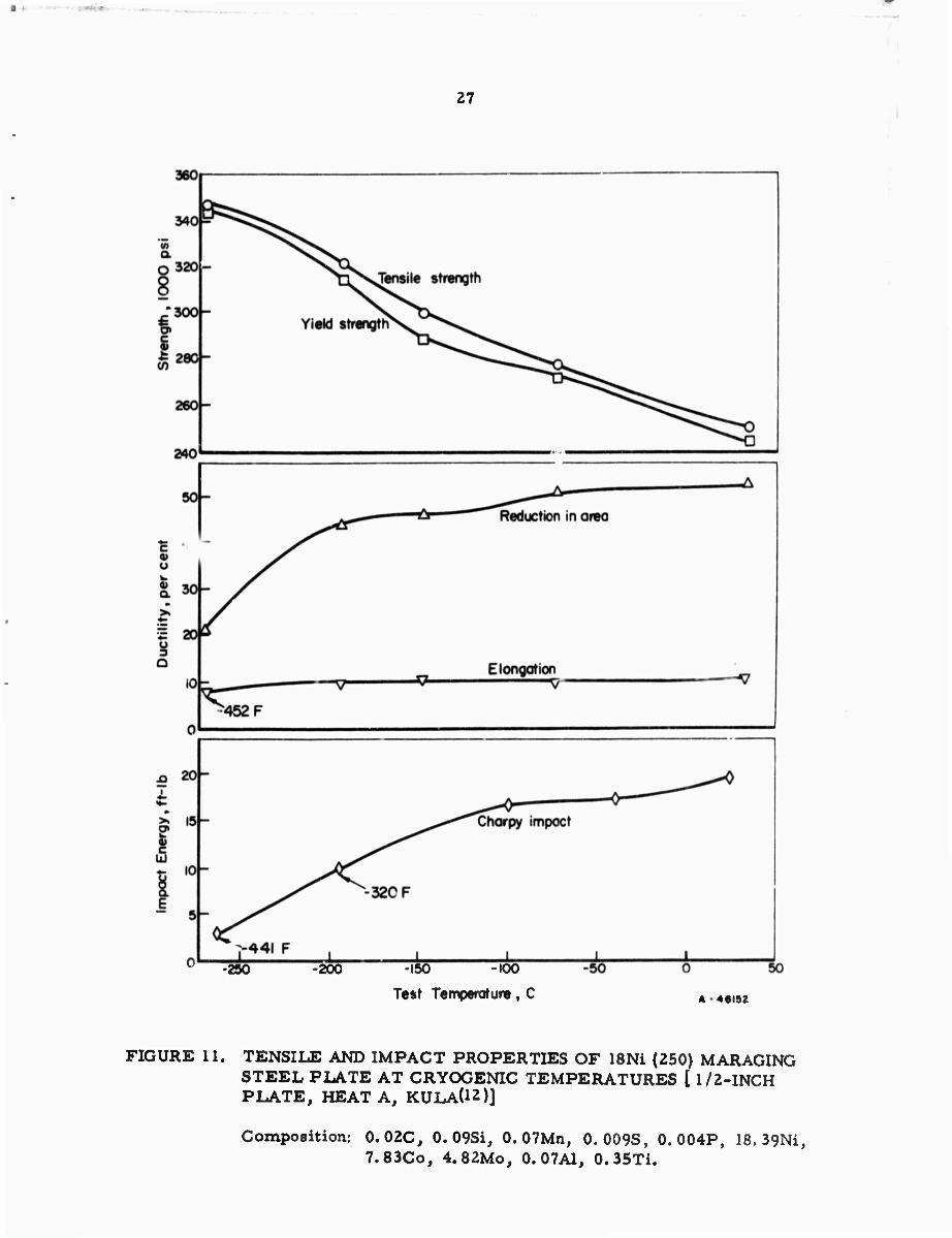
The effects of notch severity and test direction on axial fatigue strength are shown in Figures 29 and 30. Available data for forgings, shown in Figure 29, indicate a mod- erate superiority in the longitudinal direction; this may be peculiar to the specific test material, since no significant effect of directionality is found for bars at lifetimes ex- ceeding 10 cycles, as shown in Figure 30.
In the case of sheet, no notched-fatigue data were found. However, data presented in Figure 31 indicate that pits and other surface defects present in as-rolled sheet act as notches and may lower fatigue strength appreciably.
Limited axial-fatigue data at 650 F are shown for bars in Figure 32. These data indicate fatigue strength between 105 and 10? cycles is significantly higher at 650 F than at room temperature for both smooth and notched specimens.
The effect of notch severity is re-examined in Figure 33, in which the fatigue- strength reduction factor Kf for each set of notched data is plotted at various lifetimes. Past experience with other alloys, including steels and aluminum alloys, suggests that the maximum value of Kf would be approximately equal to Kt, the stress-concentration factor, and that this value would be reached at around 10^ cycles. The fact that this is not the case for some of these aata suggests they should be used with caution.

I09
KJ6
Cyc
les
to F
ailu
re
A
4
61
59
FIG
UR
E 2
5.
FA
TIG
UE C
UR
VE
S F
OR 1
8Ni
(250
) A
ND 1
8Ni
(300
) M
AR
AG
ING S
TE
EL B
AR 3
/4-I
NC
H D
IAM
ET
ER
F
RO
M A
XIA
L-L
OA
D F
AT
IGU
E T
EST
S^23)

240|
I
Cyc
les
to R
iilur
e A
-46I6
0
FIG
UR
E 2
6.
FA
TIG
UE C
UR
VE
S F
OR
I8N
i (2
50)
AN
D
18N
i (3
00)
MA
RA
GIN
G S
TE
EL B
AR 3
/4-I
NC
H D
IAM
ET
ER
F
RO
M R
OT
AT
ING B
EA
M F
AT
IGU
E T
ES
TsC
2^)

100
80
t
6
0
40
20
Tens
ile
Stre
ngth
, 000 p
si
284
28
1
0.2
2
70
Va
cuum
mel
t
Air
mel
t
Hea
t R
ef
2417
8 an
d 23
992
3
7
06989 a
nd
0708
1
21
} —
38
Gro
und
surfa
ce
L
Long
itudi
nal
ST
S
hort
trans
vers
e
""* —
— —
, 1^.
^r^F
orgi
ngs
She
et /
vacu
um
mel
t- JL
air
melK
Nat
e:
Cur
ves
indi
cate
min
imum
bo
unda
ries
of
avai
labl
e d
ata
poin
ts
I04
I05
Cyc
les
io
Failu
re
10'
A. 4
9114
4^
-vl
FIG
UR
E 2
7.
EF
FE
CT O
F M
AT
ER
IAL F
OR
M A
ND M
EL
TIN
G P
RA
CT
ICE O
N U
NN
OT
CH
ED
AX
IAL
F
AT
IGU
E S
TR
EN
GT
H O
F 1
8 P
ER C
EN
T N
ICK
EL M
AR
AG
ING S
TE
EL
S A
T R
OO
M
TE
MP
ER
AT
UR
E
Age
d at 9
00 F
fo
r 3
hr.

I 25
&
i a» CO
I o
100
80
Tens
ile
Stre
ngth
, 10
00 p
si
Hea
t R
ef.
| B
ors
(vac
uum m
elt) 2
81
06989 a
nd 0
7081
21
Pla
te (
vacu
um m
elt)
232
—
20
She
et/a
ir m
elt
\ ^V
gro
und s
urfa
ce] 2
70
—
38
1
Bar
s an
d pl
ate,
rota
ting
beam
S
heet
, re
vers
ed
bend
ing
>R
=-I
.O
Not
e: C
urve
s i
ndic
ate
min
imum
boun
darie
s of
avai
labl
e da
ta p
oint
s
10*
I05
Cyc
les
to
Failu
re
O1
A.4
5II5
t
FIG
UR
E 2
8.
EF
FE
CT O
F M
AT
ER
IAL F
OR
M A
ND M
EL
TIN
G P
RA
CT
ICE O
N U
NN
OT
CH
ED
FL
EX
UR
AL
F
AT
IGU
E S
TR
EN
GT
H O
F 1
8 P
ER C
EN
T N
ICK
EL M
AR
AG
ING S
TE
EL
S A
T R
OO
M
TE
MP
ER
AT
UR
E
Age
d a
t 90
0 F t
at
3 h
r.
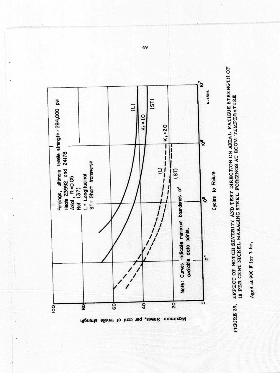
100
I u I en 6 E >< o
80
T
Forc
ings
, u
ltim
ate
tens
ile s
tren
gth
= 2
84
,00
0
psi
Hea
ts 2
3992
and
241
78
Axi
al,
R=
0.0
5
Ref
. (3
7)
L= L
ongi
tudi
nal
ST= S
hort
trans
vers
e
Not
e;
Cur
ves
indi
cate
min
imum
boun
derie
s of
av
aila
ble
data
poin
ts.
10'
105
10*
t
10'
A.4
5116
Cyc
les
to
Failu
re
FIG
UR
E 2
9.
EF
FE
CT O
F N
OT
CH S
EV
ER
ITY A
ND T
ES
T D
IRE
CT
ION
ON A
XIA
L F
AT
IGU
E S
TR
EN
GT
H O
F
18 P
ER
CE
NT N
ICK
EL M
AR
AG
ING S
TE
EL F
OR
CIN
GS A
T R
OO
M T
EM
PE
RA
TU
RE
Age
d at 9
00 F
for
3 hr.

FIG
UR
E 3
0.
E
FF
EC
T O
F N
OT
CH S
EV
ER
ITY
AN
D T
ES
T D
IRE
CT
ION O
N A
XIA
JL
FA
TIG
UE S
TR
EN
GT
H O
F
18 P
ER
CE
NT N
ICK
EL M
AR
AG
ING
ST
EE
L B
AR
S A
T R
OO
M T
EM
PE
RA
TU
RE
100
80
60
40
20
1
1
Bar
s,
ultim
ate
tens
ile
stre
ngth
= 2
81,0
00
psi
Hea
ts
06
98
9 a
nd
0708
1 A
xial,
R=
0.I0
R
ef.
(21)
Ls
Lon
gitu
dina
l S
T= S
hort
trans
vers
e
Not
e:
Cur
ves
ind
icat
e m
inim
um
boun
darie
s of
avai
labl
e da
ta
poin
ts
(LÖ
ST
)
(L)
K t=I
O
K t=
2.4
K t=
3.3
10'
10=
10*
10'
Cyc
les
to
Failu
re
A-4
5117
o
Age
d a
t 90
0 F f
or
3 h
r.

100
■&
8
0
Z
w
I 4
0
x o 5
20
She
et,
ultim
ate
ten
sile
stre
ngth
= 2
7r.)
,000
psi
A
xial
, R
s0.
l to 0
.2
Ref
. (3
8)
—
Sur
face
grou
nd
befo
re
heot t
reat
men
t, rh
en
pick
ted
——
A
s-re
ceiv
ed
surfa
ce,
pick
led
Not
e: C
urve
s i
ndic
ate
min
imum
bo
unda
ries
of
avai
labl
e d
ata
poin
ts
Gro
und
>As
rece
ived
10'
10 5
Cyc
les
to
Failu
re
I06
I0
7
A. 4
5118
ai
FIG
UR
E 3
1.
EF
FE
CT O
F S
UR
FA
CE C
ON
DIT
ION O
N A
XIA
L F
AT
IGU
E S
TR
EN
GT
H O
F
18 P
ER C
EN
T N
ICK
EL
M
AR
AG
ING S
TE
EL S
HE
ET A
T R
OO
M T
EM
PE
RA
TU
RE
Age
d a
t 90
0 F f
or
3 h
r.

Cyc
les
to
Failu
re
A-4
5119
FIG
UR
E 3
2.
EF
FE
CT O
F N
OT
CH
SE
VE
RIT
Y A
ND T
ES
T D
IRE
CT
ION O
N A
XIA
L F
AT
IGU
E S
TR
EN
GT
H O
F
18 P
ER
CE
NT N
ICK
EL
. M
AR
AG
ING S
TE
EL B
AR
S A
T 6
50 F
Age
d at
900
F f
or 3 h
r.

CO
o c c D
</)
c
u I u
(A (A
00
c
'L 2
Kt =3.3 (bars, ref. 21)
.JL
/
/
./
^
#x^,<^650 F "^,,*,,,N>^ y' Room temperature
/ N
K ts 2.0 (forgings, ref. 37)
Iw
V =2.4 Mrs, ref. T) t I
/
A
lO3
Cycles to Failure
l<f !0' A.49t20
FIGURE 33. FATIGUE-STRENGTH REDUCTION FACTORS FOR NOTCHED 18 PER CENT NICKEL MARAGING STEFL BARS AND FORGINGS
Aged at 900 F for 3 hours.

54
CREEP AND RUPTURE STRENGTH
Very limited creep and rupture datci have been reported for the 18 nickel ma raging steels. In this review, these data have bsen nondimensionaiized to eliminate strength as a variable. In this way they can be correlated by means of the Larson-Miller parameter plot, as shown in Table 13. Smooth curves are shown drawn through the correlated drta. points in Figure 34. In view of the limited quantity of data and relatively high degree of scatter, these values should be considered indicative, but not necessarily typical, of the creep and rupture properties of these steels.
A modified composition of the maraging steels has been developed for improved high-temperature stability. (22) Stress-rupture data for this alloy which contains 15. 2 per cent nickel are presented in Table 14 and in Figure 35.
PROPERTIES OF PRESSURE VESSELS OF MARAGING STEEIÄ
Many of the projected applications for maraging steels involve their use as pres- sure vessels such as lightweight storage vessels for high-pressure gases and solid- propellant rocket-motor cases. The ultimate test to determine the feasibility of the maraging steels for these applications is to fabricate subscale or full-scale vessels and burst them. This has been done to a limited extent, and available data are presented in Table 15. Diameters of vessels range from Z inches to full-size missile cases. With but one exception the burst stress-tensile strength ratios were 1. 05 or greater. This indicates that under biaxial loading the alloy has sufficient toughness to take at least partial advantage of the theoretical increase in strength that is associated with 2:1 bi- axial stressing.
Based on available burst-test data, the only other commercial steel which has ex- ceeded 330,000-p8i burst stress is Type H-ll(46\
Consequently, it appears that, in addition to such advantages as simple heat treat- ment, satisfactory weldability for many applications, etc. , the maraging steels have potentially high burst strengths when fabricated into pressure vessels.
In tests on a series of pressure vessels of a number of high-strength steels, small part-through cracks were intentionally produced in the shells of the vessels, t4'' After the vessels were burst tested, a correlation was made between crack depth as per cent of wall thickness and burst stress. The pressure vessels of the maraging steels had higher burst stresses for given crack depths than any of the other steels according to preliminary data.
Fabrication of pressure vessels requires welding of closures and other components to complete the vessels. The mechanical properties of the welds themselves are a very important aspect to consider in selection of the material and fabrication program. This subject is reviewed in Defense Metals Information Center Memorandum 182 dated October 16, 1963.

TABLE 13, CREEP AND RUPTURE STRENGTHS OF 18 PER CENT NICKEL MARAGING STEELS
(Aged 900 F for 3 hours)
Temp, Stress F 1000 P$i Per CenKa)
0.1 Per Cent Creep
Hr m 0.2 Per Cent
Creep Hr P
1 Per Cent Creep
Hr P Rupture
Hr
80u 800 900 900
1000 1000
1000
175 150 150 125 100 75
67 57 57 48 38
29
Laboratory Heat. (250) Grade(cX39)
-- -
Heat 23832. (250) GradeC40)
Heats 06989 and 07081. (300) GradeC21)
oou 180 64 1700 25.8 Mi ..
180 64 1500 25.7 M — 217 77 55 24.1 500 25.2 Mi
208 74 30 23.8 600 25.3 — 800 110 3E 70 27.5 200 28.1 1300 29.1
110 39 80 27.6 200 28.1 1200 29.1 115 41 35 27.4 190 28.1 1200 29.1 115 41 90 27.7 250 28.2 1200 29.1 150 53 10 26.5 40 27.2 320 28.4 150 53 15 26.7 60 27.4 380 28.4 180 64 1.4 25.4 5 26.1 70 27.5 180 64 1.9 25.5 8 26.3 110 27.8
Heat 23831. (300) GradeC40)
38 27.2
561 28.6 (5.7 28.3
38 29.4 4.6 30.2 48 31.7
244
277
32.7
28.3
800 1000
175 75
61 26
5;« 226
28.6 32.7
(a) Per cent of ultimate tensile strength at room temperature. (b) Lason-Miller parameter P = (T -t- 460X20 + log t) x 10 "3. where T is temperatur» in degrees F and t is time in hours. (c) 19.15Ni, 7.0CO, 4.9Mo, and 0.41Ti:
Heat Ni Co Mo Ti
23832 18.34 7.69 5.20 0.45 06969 18.62 8.74 4.76 0.63 07081 18.61 9.14 4.72 0.58 23831 18.20 9.05 4.84 0.69

26 28 30
(T + 460)(20+Iog t)XI0'S
FIGURE 34. CREEP AND RUPTURE STRENGTHS OF 18 PER CENT NICKEL MARAGING STEELS(21*40|39)
Aged at 900 F for 3 hours.

57
TABLE 14. STRESS-RUPTURE PROPERTIES OF 15 PER CENT NICKEL MARAGING STEEL AS 3/4-INCH BAR^22)
(Specimens annealed at 1800 F, air cooled, and aged at 900 F for 3 hours.)
Rupture Stress Life,
hours L-M
Paramete r(b) Elongation,
Temperature, F 1000 Psi Per Cent(a) per cent
800 220 73 834 28.9 5 800 240 80 292 28.4 8
900 125 42 756 31.2 8 900 150 50 302 30.6 7 900 175 58 95 29.9 10 900 200 67 35 29.3 9
1000 80 27 433 33.1 7 1000 90 30 187 32.5 9 1000 100 33 104 32.2 10 1000 125 42 29 31.3 12
(a) Per cent of ultimate tensile strength at room temperature. The tensile strength at room temperature is 300,000 psi. (b) Larson-Miller parameter.
30 100 300 Rupture Life,hours
lOOO A-46I6I
FIGURE 35. STRESS-RUPTURE CURVES FOR 15 PER CENT NICKEL MARAGING STEEL AS 3/4-INCH BAR<22)
The heat treatment and composition are the same as in Table 14. Numbers in parentheses are for the per cent austenite in the test section after rupture.

58
TABLE 15. BURST TEST DATA ON 18 PER CENT NICKEL MARAGING STEEL PRESSURE VESSELS
Maiaging Steel Grade
Vessel Dimensions
Vessel Diameter,
inches
Wall Thickness,
inch Burst Hoop
Stress, 1000 psi
Burst Stress-Tensile Strength Ratio Fabrication Method Reference;
(250)
(300)
0103 0203
•
PV#1 PV#2 PV#4
(Typhoo missile) (Typhon missile)
0.047
0.047 0.040
272
281
346 374 362
1.05 Flow turned, annealed, closures 1.05 welded on, aged 900 F 3 hr
1.20 Drawn, annealed, welded, aged 1.30 Drawn, welded, aged 1.27 Drawn, annealed, welded, aged
(one drawn cup 18-9-5 com- position, the other 18-8-5)
(«) HT ■ heat treated. (b) Vessel failed prematurely; fracture initiated at weld undercut.
41
43
(300) 1 6 .. 338 1.16 Forged, machined, HT(a) 42 2 6 — 342 1.18 Ditto 3 -- 323 1.11 Forged, machined, girth welded. 4 -- 338 1.16 HT 5 — 344 1.18 Shear-spun, HT, cold worked 6 -- 298 (b) Shear-spun, girth welded, HT 7 -• 1.19 Shear-spun, HT 8 -- 350 1.14 Shear-spun, HT
(300) 2 0.140 336 1.07 Drawn (seamless), 1500 F 1 hr. 44 j 3 0.140 330 1.05 air cooled, aged 900 F 6 0.140 349 1.11 3hr
(300) S/Nl 24 0.130 328 1.13 Flow turned, annealed, girth 34 S/N2 24 0.130 328 1.13 welded, aged 900 F 3 hr
(300) -- (Pershing case) 342 1.19 -- 45

59
REFERENCES
(1) "18% Nickel Maraging Ste^r', Interim Data Sheet TL 10, The International Nickel f Company, Inc. , 67 Wall Street, New York 5, New York (November 26, 1962).
(2) Decker, R. F. , Yeo, R.B.G. , Eash, J. T. , and Bieber, C. G. , "The Maraging Steels", Materials in Design Engineering, 55, pp 106-111 (May, 1962).
(3) Gilewicz, E. P. , "Evaluation of Strength and Fracture Toughness of Maraging Steels", Curtiss-Wrigbt Corporation, Wood-Ridge, New Jersey, "Maraging Steel Project Review", ASD-TDR-63-262, Aeronautical Systems Division, Wright- Patterson Air Force Base, Ohio, pp 341-381 (May, 1963).
(4) Crimmins, P. P. , "Evaluation of High Nickel Maraging Steel for Application in Large Booster Motor Fabrication", Aerojet-General Corporation, Sacramento, California, "Third Maraging Steel Project Review", Report No. RTD-TDR-63- 4048, Air Force Materials Laboratory, Wright-Patterson Air Force Base, Ohio, pp 95-183 (November, 1963).
(5) Curtiss-Wright Corporation, Wood-Ridge, New Jersey; preliminary information obtained on an Air Force contract.
(6) Wilcox, R. J. , "Investment Cast Maraging Steel by the Monoshell Process", Misco Precision Casting Company, Division of Howe Sound Company, "Third Maraging Steel Project Review", Report No. RTD-TDR-63-4048, Air Force Materials Lab- oratory, Wright-Patterson Air Force Base, Ohio, pp 503-526 (November, 1963).
(7) Aggen, G. N. , "INGO Maraging Steel-300 KSI Ni-Co-Mo Alloy", Allegheny Ludlum Steel Corporation, Brackenridge, Pennsylvania (January 25, 1962).
(8) Smith, H. R. , Anderson, R. E. , and Bingham, J. T. , "A User Evaluates Marag- ing Steels", Metal Progress, 82 (5), pp 103-105, 128, 131A, 132 (November, 1962).
(9) Aerojet-General Corporation, Sacramento, California; preliminary information on an Air Force contract.
(10) Bingham, J. T., "Fasteners from Maraging Steel", Hi-Shear Corporation, Tor- rance, California, "Maraging Steel Project Review", ASD-TDR-63-262, Aero- nautical Systems Division, Wright-Patterson Air Force Base, Ohio, pp 178-194 (May, 1963).
(11) Lewis, R. E. , "Anisotropy of Young's Modulus in 18% Nickel Maraging Steel", Lockheed Missiles & Space Company, Palo Alto, California, "Third Maraging Steel Project Review", Report No. RTD-'TDR-63-4048, Air Force Materials Laboratory, Wright-Patterson Air Force Base, Ohio, pp 369-385 (November, 1963).
(12) Kula, E. B. , and Hickey, C. F. , Jr., "Evaluation of Maraging Steel at U. S. Army Materials Research Agency", Watertown Arsenal, Watertown, Massachusetts, "Third Maraging Steel Project Review", Report No. RTD-TDR-63-4048, Air Force Materials Laboratory, Wright-Patterson Air Force Base, Ohio, pp 439-455 (November, 1963).

60
(13) Simenz, R. F., and Macoritto, W. L. , "Preliminary Evaluation of Maraging Steels", Lockheed-California Company, Report No. LR 16485 (May 30, 1963).
(14) Sparks, R. B., "Properties of Maraging Steel Press Forgings", Wyman Gordon Company, Worcester, Massachusetts, "Maraging Steel Project Review", ASD- TDR-63-262, Aeronautical Systems Division. Wright-Patterson Air Force Base, Ohio, pp 195-222 (May, 1963).
(15) Hanna, G. h, 9 and Steigerwald, E. A., "Fracture Characteristics of Structural Metals", Thompson Ramo Wooldridge, Inc. , Cleveland, Ohio, Report ER-5426, Bureau of Naval Weapons Contract N 600(19)-5883l (June 30, 1963).
(16) Bhat, G. K. , and Persin, W. J. , "Preliminary Evaluation of Mechanical Strength and Fracture Toughness of Thick Plate Maraging Steel", Mellon Institute, Pittsburgh, Pennsylvania, "Maraging Steel Project Review", ASD-TDR-63-262, Aeronautical Systems Division, Wright-Patterson Air Force Base, Ohio, pp 251- 270 (May, 1963).
(17) Yates, D. H. , Vanadium-Alloys Steel Company, Latrobe, Pennsylvania, Vanadium-Alloy s data.
(18) May, J. A. , "18Ni Maraging Steel in Elevated Temperature Airframe Design", North American Aviation, Inc., Los Angeles, California; "Third Maraging Steel Project Review", Report No. RTD-TDR-63-4048, Air Force Materials Laboratory, Wright-Patterson Air Force Base, Ohio, pp 549-570 (November, 1963).
(19) Raney, G. A. , Adams, D. S. , and Hof statter, A. F. , "Evaluation of 18Ni-Co-Mo (250) Maraging Steel", MR 62-12 Report of the Ryan Aeronautical Company, San Diego, California (November 7, 1963).
(20) U. S. Naval Engineering Experiment Station, Information from a Navy contract.
(21) Schleicher, R. L. , private communication including NAA Data Sheets on 18Ni- Maraging Steel (300 Grade), North American Aviation, Incorporated, Los Angeles, California (April 22, 1963).
(22) Floreen, S. , and Decker, R. F. , "Maraging Steel for 1000 F Service", American Society for Metals Transactions Quarterly, 56 (3), pp 403-411 (September, 1963).
(23) Lumm, J. A. , and Sampson, H. B. , "Nickel Maraging Steels, Preliminary In- vestigation of 250 and 300 Bar", Report No. NA63H-202, North American Aviation, Inc. , Columbus Division, Columbus 16, Ohio (March 15, 1963).
(24) Kaltenhauser, R. , "Data on Nickel Maraging Steels", Allegheny Ludlum Steel Corporation, Brackenridge, Pennsylvania (April 11, 1963).
(25) Arnold, S. V. , "Aging Response of 18% Ni-Co-Mo Steel", Technical Report WAL TR 320. 1/11, Watertown Arsenal Laboratories, Watertown, Massachusetts (February, 1963).
(26) "RSM 250: Vacuum Melted Maraging Steel", Data Sheet No. 13 and No. 15, Re- public Steel Corporation (April 8, 1963).

61
(27) Kula, E. B. , and Hickey, C. F. , 3v., "Evaluation of Maraging Steels at Army Materials Research Agency", Watertown Arsenal, Watertown, Massachusetts, "Maraging Steel Project Review", ASD-TDR-63-262, Aeronautical Systems Divi- sion, Wright-Patterson Air Force Base, Ohio, pp 236-250 (May, 1963).
(28) Lewis, R. E., "Fracture Toughness m Plate Thicknesses of 18% Nickel Maraging Steels", Lockheed Missiles and Space Company, Palo Alto, California, "Third Maraging Steel Project Review", Report No. RTD-TDR-63-4048, Air Force Mate- rials Laboratory, Wright-Patterson Air Force Base, Ohio, pp 387-405 (November, 1963).
(36) Romine, H. E. , "Plane Strain Fracture Toughness Measurements of Solid Booster Case Materials", U. S. Naval Weapons Laboratory, Dahlgren, Virginia, "Third Maraging Steel Project Review", Report No. RTD-TDR-63-4048, Air Force Mate- rials Laboratory, Wright-Patterson Air Force Base, Ohio, pp 185-212 (November, 1963).
(29) Novak, C. J. , and Diran, L. M. , "What Are the Effects of Residual Elements in Maraging Steels", Journal of Metals, jjj (3), pp 200-204 (March, 1963).
(30) Warke, W. R. , "Proceedings of the April 2-3, 1963, Meeting to Discuss Fracture- Toughness Specifications for Maraging Steel Plate for Big Boosters", meeting held at Battelle Memorial Institute (April 2-3, 1963).
(31) Sippel, G. R. , and Vonnegut, G. L., "Partial Thickness Crack Fracture Tough- ness of 18% Ni Steel, D6 Steel and Ti-6A1-4V Alloy", Allison Division, General Motors Corporation, Indianapolis, Indiana, "Maraging Steel Project Review*', ASD-TDR-63-262, Aeronautical Systems Division, Wright-Patterson Air Force Base, Ohio, pp 30-45 (May, 1963).
(32) Steigerwald, E. A. , and Hanna, G. L. , "Initiation of Slow Crack Propagation in High-Strength Materials", American Society for Testing and Materials, Proceed- ings, 62, pp 885-905 (1962).
(33) Corn, D. L. , "Evaluation of 18Ni-9Co-5Mo (300 ksi) Maraging Steel Sheet", Part 1, Mechanical Properties, Douglas Aircraft Company, Inc. , Santa Monica, California, SM Report 43110 (November 27, 1963).
(34) Sippel, G. R., and Vonnegut, G. L., "Evaluation of 18% Ni-Co-Mo Maraging Steel for Heavy and Thin Wall Rocket Motor Case Applications", Materials Research Laboratory, Allison Division, General Motors Corporation, Indianapolis, Indiana, "Third Maraging Steel Project Review", Report No. RTD-TDR-63-4048, Air Force Materials Laboratory, Wright-Patter son Air Force Base, Ohio, pp 213-273 (November, 1963).
(35) Saperstein, Z. P., and White son, B. V., "The Properties of Welded 18Ni-7Co- 5Mo Plate", Douglas Aircraft Company, Inc. , San a Monica, California, Engineer- ing Paper No. 1696, "Third Maraging Steel Project Review", Report No. RTD- TDR-63-4048, Air Force Materials Laboratory, Wright-Patterson Air Force Base, Ohio, pp 1-42 (November, 1963).

■ ■■***'»vfn.mm*,'~'''
62
(37) Nordquist, F. C. , "IPNiCoMo (300) Maraging Steel Forgings", General Dynamics/ Fort Worth, Fort Worth, Texas, Paper FZM-2731, "Maraging Steel Project Re- view", ASD-TDR-63-262, Aeronautical Systems DivisioYi, Wright-Patterson Air Force Base, Ohio, pp 106-138 (May, 1963).
(38) Ryan Aeronautical Company, San Diego, California, preliminary information.
(39) "18% Nickel Maraging Steel", Preliminary Data Sheet, International Nickel Com- pany, Inc. , New York, New York (September 26, 1961).
(40) DeVries, R. P. , "The Effect of Processing Factors and Size on '-.he Properties of Commercially Produced 18% Ni-Co-Mo Maraging Steels", Allegheny Ludlum Steel Corporation, Watervliet, New York, presented at Symposium on Maragmg Steels at Wright-Patterson Air Force Base, Ohio (May 14, 1962).
(41) Duxjkle, J L. , Randolph, R. E. , and Bloomy A. E. , "Development of Medium Range Typhon Chambers from 18 Per Cent Nickel (250) Steel", Allegany Ballistics Laboratory, Cumberland, Maryland (July 18, 1963).
(42) Johnson, R. R. , "Subscale and Full Scale Hydrostatic Testing of Vessels Fabri- cated from 18 Per Cent Nickel Mr raging Steel", Curtis»-Wright Corporation, Wood-Ridge, New Jersey, "Maraging Steel Project Review", ASD-TDR-63-262, Aeronautical Systems Division, Wright-Patterson Air Force Base, Ohio, pp 325- 340 (May, 1963).
(43) Burros, T. H. , "Metallurgical Investigation of Maraging Steels for Missile Motor Cases", Thiokol Chemical Corporation, Huntsville, Alabama, "Maraging Steel Project Review", ASD-TDR-63-262, Aeronautical Systems Division, Wright- Patterson Air Force Base, Ohio, pp 295-308 (May, 1963).
(44) Melville, A. , "Metallurgical Evaluation of 18 Per Cent Nickel Maraging Steel (300 KSI Strength Level)", Thiokol Chemical Corporation, Wasatch Division, Brigham City, Utah, "Third Maiagxng Steel Project Review", Report No. RTD- TDR-63-4048, Air Force Materials Laboratory, Wright-Patterson Air Force Base, Ohio, pp 327-368 (November, 1963).
(45) Sparks, R. B., "Working With Maraging Steels ... . Forging", Metal Progress, 84 (1), pp 74-77 (July, 1963).
(46) Curtiss-Wright Corporation, Wood-Ridge, New Jersey, preliminary information obtained on Navy contract (September, 1959).
(47) Bhat, G. K. , and Persin, W. J., "Evaluation of Maraging 18% Nickel Steel Sheet and Plate, Phy-^al and Mechanical Properties and Some Fabrication Character- istics", Mellon Institute, Pittsburgh, Pennsylvania, "Third Maraging Steel Project Review", Report No. RTD-TDR-63-4048, Air Force Materials Laboratory, Wright- Patterson Air Force Base, Ohio, pp 275-302 (November, 1963).
(48) Padian, W. D., Toy, A., xnd Robelotto, R., "Electron Beam Welding of One-Half Inch T^ick Maraging Stee1 , North American Aviation, Inc. , Los Angeles Division, Los Angeles, California, Third Maraging Steel Project Review", Report No. RTD- TDR-63-4048, Air Fore Materials Laboratory, Wright-Patter son Air Force Base, Ohio, pp 43-72 (November, 1963).

63 and 64
(49) Adams, D, S., "Effect of Sheet Thickness and Gauge Length on the Tensile Ductil- ity of ISNiCoMo (250) and AISI 4130", Re ort MR 63-1 of the Ryan Aeronautical Company, San Diego, California (February 6, 1963).
(50) Repulbic Aviation Corporation, Mineola, Long Island, New York, preliminary information on an Army contract.
(51) Sampson, H. B. , "Nickel Maraging Steels; Preliminary Investigation of 250 and 300 Sheet (ISNiCoMo)" North American Aviation, Inc. , Columbus Division, Columbus, Ohio, Report No. NA62H-622 (August 29, 1962).
(52) Lumm, J. A. , and Federico, A. M. , "Preliminary Mechanical Property Evalua- tion of 250 and 300 Grade 18Ni Haraging Steel", North American Aviation, Inc. , Columbus Division, Columbus, Ohio, Report No. 132-225-63 (August 28, 1963).
(53) "Vascomax 250 and 300-18% Nickel Ultra High Strength Maraging Steels", Vana- dium Alloys Steel Company, Latrobe, Pennsylvania, Trade Literature (Received April 10, 1962).
(54) Douglas Aircraft Company, Inc. , preliminary infornaation on an Air Force contract.
(55) "Plates Made From 18% Nickel Maraging Steel", Metallurgical Report prepared for Experiment No. 1452, Bethlehem Steel Company, Bethlehem, Pennsylvania (April 6, 1963).
(56) Davis, R. A,, "Fracture Toughness and Stress Corrosion Testing of High Strength Steels", The Boeing Company, Airplane Division, Renton, Washington, "Third Maraging Steel Project Review", Report No. RTD-TDR-63-4048, Air Force Mate- rials Laboratory, Wright-Patterson Air Force Base, pp 527-536 (November, 1963).
(57) Steigerwald, E. A., Thompson Ramo Wooldtidge, Inc. , Cleveland, Ohio, private conununication of April 11, 1963.
(58) Morris, G. , "Evaluation of Vascomax 300 (18% Nickel Steel) Bar", Report No. 513-342, McDonnell Aircraft Corporation, St. Louis, Missouri (December 10, 1962).
(59) "Maraging Steels", Allegheny Ludlum Steel Corporation, Pittsburgh, Pennsylvania, preliminary data (trade literature) (received December, 1961).
(60) Hofstatter, A. F. , "Elevated Temperature and Notch Strength Properties of 18NiCoMo (250) Marage Steel", Ryan Aeronautical Company, San Diego, California, Metallurgical Research Report MR 63-9 (August 27, 1963).
i) American Brake Shoe Company, Mahwah, New Jersey, preliminary information on an Air Force contract.
(62) Sadowski, E. P., and Decker, R. F., "Cast Maraging Steel", Modern Castings, 32 (2), pp 26-35 (February, 1963).

APPENDIX
PROPERTY DATA

'"I LllUIWlliU ' u
A-l
TABLE A-l. C(MvIP0SITIONS OF HEATS OF 18NI (250) MARAGING STEEL SHOWN IN FIGURE flCQ
Size of
Heat Heat, pounds
Melting Method
Composition, per cent C Mn P S Si Ni Mo Co Ti Al B Zr Ca
06137 1,000 VAR 0.01 0.11 0.007 0.004 0.07 18.2 4.8 7.6 0.42 0.09 0.004 .. 0.0^a> o.orf«; 0.0^
23664 1,000 VAR C.016 0.05 0.002 0.007 0.06 18.2 4.8 8.0 0.37 0.09 0.004 0.01 40059 4,000 VAR 0.03 0.03 0.003 0.006 0.03 19.1 4.4 8.2 0.40 0.04 0.003
o.oo^a)
0.003^ a)
0.02 84625 19,000 Air arc 0.026 0.010 0.008 0.010 0.064 18.7 4.59 7.87 0.24 0.085 0.01
o.oi(a)
0.0fra' A 6824 1,000 Aiiind. 0,02 0.11 0.007 0.007 0.09 18.54 5.34 7.38 0.44 0.095 A6939 1,000 Air Ind. 0.03 0.15 0.004 0.013 0.09 18.2 4.7 7.4 0,35 0.005 0.002 — X51623 25,000 Air arc 0.026 0.05 0.003 0.010 0.09 18.34 4.62 7.61 0.47 0.15 0.003
o.oo;/a' " --
X 51742 25,000 Air arc 0.022 0.02 0.003 0.008 0.10 17.63 4.80 7.32 0.42 0.079 ■•
(a) Per cent added.

!
A-2
TABLE A-2. COMPOSITIONS OF HEATS OF 18Ni(300) MARAGING STEEL MADE WITH INTENTIONAL VARIATIONS IN TITANIUM, MOLYBDENUM, AND COBALTC7)
Composition, per cent(a) Heat(b) C Mn Si Ni Mo Co Ti Al
RV477 .018 .002 .006 8.29 4.95 9.10 0.40 0.089 RV472 .021 .002 .006 18.44 4.95 9.11 0.55 0.027 RV490 .030 .002 .006 18.50 5.01 9.02 0.71 0.120 RV475 .023 .004 .007 18.40 4.96 8.99 0.84 0.042 RV476 .020 .002 .006 18.60 4.90 9.05 1.00 0.078
RV478 .027 .003 .019 18.46 4.70 8.96 0.55 0.084 RV472 .021 .002 .009 18.44 4.95 9.11 0.55 0.027 RV480 .027 .003 .009 18.69 5.30 9.07 0.53 0.093
RV482 .026 .002 .019 18.26 4.70 9.13 0.71 0.073 RV490 .030 .002 .019 18.50 5.01 9.02 0.71 0.120 RV48I .026 .002 .024 18.30 5.1? 9. 11 0.73 0.065
RV448 .029 .002 .009 18.51 4.92 8.46 0.52 0.089 RV472 .021 .002 .009 18.44 4.95 9.11 0.55 0.027 RV451 .030 .003 .009 18.33 5.05 9.46 0.55 0.049
RV483 .027 .002 .014 18.51 4.95 8.5 2 0.71 0.084 RV490 .030 .002 .019 18.50 5.01 9.02 0.71 0.120 RV473 .019 .003 .009 18.40 4.95 9.34 0.70 0.044
(«) S and P were let« dun .010 per cent. (b) All been were melted in a vacuum Induction furnace and poured Into 4-inch square 60-pound ingoo. The Ingots were preu
forged to bar and rolled to 0.125-inch strip. The strip was cold rolled to 0.062-inch sheet.

A-3
TABLE A-3. ROOM-TEMPERATURE TENSILE PROPERTIES OF 0. 062-INCH T&CK SHEET MADE FROM THE HEATS LISTED IN TABLE A-2(a)(7)
Yield Yield Strength Strength
0.02% 0.2% Tensile Elongation in Chemical Test Offset, Offset, Strength, 2 Inches, Hardness,
Heat Variation Direction 1000 psi 1000 psi 1000 psi per cent Rc
IL Variations
RV 477 0.40 Ti L 243 270 272 2.5(b) 53.0 RV 472 0.55 Ti L 235 272 280 2.5 54.1 RV 490 0.71 Ti L 214 293 300 3.0 55.2 RV 475 0.84 Ti L 246 313 314 2. 0(b) 56.7 RV 476 1.00 Ti L 273 307 308 2. 0(b) 57.2 RV 477 0.40 Ti T 246 280 280 3. 0(a) 53.0 RV 472 0. 55 Ti T 240 287 287 2.5(b) 54.1 RV 490 0.71 Ti T 234 299 299 2. 5(b) 55.2 RV 475 0.84 Ti T 241 316 319 2. 0(b) 56.7 RV 476 1.00 Ti T 275 tc) 321 2.0(b) 57.2
Mo Variations - 0. 55 Ti
RV 478 4.70 Mo L 244 277 279 2.5 53.6 RV 472 4.95 Mo L 235 272 280 2.5 54.1 RV 480 5. 30 Mo L 249 (c) 297 2.5(b) 55.0 RV 478 4.70 Mo T 250 287 287 2. 0(b) 53.6 RV 472 4.95 Mo T 240 287 287 2.5(b) 54.1 RV 480 5. 30 Mo T 262 302 302 2.5 55.0
Mo Variations - 0. 70 Ti
RV 482 4.70 Mo L 247 286 289 3.0 54.7 RV 490 5.01 Mo L 214 293 300 3.0 55.2 RV 481 5. 19 Mo L 252 (0 299 2. 0?b) 56.2 RV 482 4.70 Mo T 253 (c) 288 2.0 54.7 RV 490 5.01 Mo T 234 299 299 2. 5(b) 55.2 RV 481 5. 19 Mo T 278 (c) 306 2.5 56.2
Co Variations - 0. 55 Ti
53.3 RV 448 8.46 Co L 232 272 276 2.5(b) RV 472 9.11 Co L 235 272 280 2.5 54.1 RV 450 9.46 Co L 248 281 284 2.5(b) 54.4 RV 448 8.46 Co T 244 281 283 2. 5(b) 53.3 RV 472 9.11 Co T 240 287 287 2.5(b) 54.1 RV 450 9.46 Co T 263 298 298 2. 5(b) 54.4

A-4
TABLE A-3. (Continued)
Yield Yield Strength Strength
0.02% 0.2% Tensile Elongation in Chemical Test Offset, Offset, Strength, 2 Inches, Hardness,
Heat Variation Direction 1000 psi 1000 psi 1000 psi per cent Rc
Co Variations - 0.70 Ti
RV 483 8.52 Co L 174 267 280 2.5^) 54.8 RV490 9.02 Co L 214 293 300 3.0 55.2 RV 473 9. 34 Co L 210 287 292 2.0 55.6 RV483 8.52 Co T 256 292 293 2.5 54.8 RV490 9. 02 Co T 234 299 299 2.5(b) 55.2 RV473 9. >4 Co T 235 294 296 2.0 55.6
(a) Annealed u 1500 F for 10 minutes, air cooled and aged at 900 F for 3 hours and air cooled. (b) Broke on or outside gage marks. (c) Fractured before 0.2%YS attained.

A-5
TABLE A-4. EFFECTS OF ALLOY CONl'ENTCa) ON THE ROOM-TEMPERATURE TENSILE PROPERTIES OF 18Ni (300) MARAGING STEEL IN THE FORM OF 0. 062 INCH SHEET, SOLUTION TREATED AT 1500 F FOR 15 MINUTES AND AGED AT 900 F FOR 3 HOURS^)
Ti Rolling
Direction
Average Mechanical P roperties
Co Mo
Yield Strength
0. 2% Offset, 1000 psi
Tensile Strength, 1000 psi
Elongation in 1
Inch, per cent
9.10 4.95 (HT. RV 477)
0.40 L T
268 273
274 279
5 9 5.4
8.96 4.70 (HT. RV 478)
0.55 L T
269 276
272 282
5.2 5.4
8.46 4.92 (HT. RV 448)
0.52 L T
278 272
280 279
5.5 5.4
9.11 4.95 (HT. RV472)
0.55 L T
277 272
283 281
5.2 5.9
9.13 4.70 (HT. RV 482)
0.71 L T
285 301
290 303
5.1 4.6
9.46 5.05 (HT. RV 450)
0.55 L T
279 289
285 294
5.4 4.9
8.52 4.95 (HT. RV 483)
0.71 L T
282 294
287 295
5.5 4.6
9. 07 5.30 (HT. RV 480)
0.53 L T
290 303
294 308
5.6 4.6
9.02 5.Ö1 (HT. RV 490)
0.71 L T
294 306
297 307
5.0 4.1
9.58 4.92 (HT. RV 473?)
0.70 L T
291 288
295 295
5.2 5.0
9.11 5.19 (HT. RV 481)
0.73 L T
306 309
308 311
4.9 5.2
8.99 4.96 (HT. RV 475)
0.84 L T
308 317
310 322
4.6 4.7
9.05 4.90 (HT. RV 476)
1.00 L T
322 327
324 337
4.4 4.0
(a) For complete compoiition of the heats see Table A -2.

A-6
TABLE A-5. LONGITUDINAL TENSILE PROPERTIES OF COLD-WORKED 18Ni (250) MARAGING STEEL(5)
Reduction Yield During Aging Aging Tensile Strength Reduction
Cold Working, Temperature, Time, Strength, 0. 2% Offset, Elongation, in Area, per cent F hours 1000 psi 1000 psi per cent
4.9
per cent
20 850 246 244 46 20 850 247 247 4.5 41 20 900 263 263 4.3 52 20 900 263 263 3.6 52 20 850 268 268 4.6 45 20 850 259 257 4.3 50 20 900 275 273 4.3 56 20 900 284 282 4.8 52 20 850 10 292 289 4.6 49 20 850 10 292 287 4.9 55 20 900 10 288 283 3.5 47 20 900 10 280 274 4.8 48
30 850 278 277 3.7 50 30 850 277 277 4.5 53 30 900 291 291 4.3 54 30 900 293 291 4.4 47 30 850 297 295 4.2 37 30 850 289 288 4.2 53 30 900 294 290 4.0 49 30 900 300 297 4.7 54 30 850 10 306 302 4.1 42 30 850 10 306 299 4.4 47 30 900 10 294 289 5.0 49 30 900 10 293 290 4.9 54
70 850 293 290 2.5 43 70 850 294 294 4.3 47 70 900 308 306 4.0 49 70 900 284 284 1.9 47 70 850 295 295 4.2 47 70 850 309 302 4.2 49 70 900 307 303 3.3 47 70 900 317 315 4.4 57 70 850 10 319 319 3.0 48 70 850 10 327 326 3.4 43 70 900 10 305 300 4.1 51 70 900 10 307 297 4.5 53

A-7
TABLE A-6. TRANSVERSE TENSILE PROPERTIES OF COLD-WORKED 18Ni (250) MARAGING STEEL(5)
Reduction Yield During Aging Aging Tensile Strength Reduction
Cold Working, Temperature, Time, Strength, 0. 2% Offset, Elongation, in Area, per cent F hours 1000 psi 1000 psi per cent per cent
20 850 264 262 4.4 54 20 850 259 257 4.7 51 20 900 285 285 3.2 46 20 900 274 274 3.1 45 20 850 289 289 2.8 49 20 850 285 281 4.5 48 20 900 291 287 4.1 47 20 850 10 301 297 4.2 41 20 850 10 305 304 2.8 43 20 900 10 301 295 4.5 42 20 900 10 303 302 3.9 41
30 850 283 282 4.2 44 30 850 291 289 3.4 45 30 900 306 301 4.0 44 30 900 306 302 3.2 49 30 850 272 272 1.2 41 30 850 302 301 3.8 39 30 900 317 310 4.1 42 30 900 305 302 4.1 43 30 850 10 324 319 3.8 44 30 850 10 321 316 3.8 42 30 900 10 316 308 3.8 47 30 900 10 315 306 4.0 44
40 850 294 294 4.0 35 40 850 286 283 3.7 43 40 900 306 301 3.6 43 40 900 304 302 3.4 44 40 850 303 303 3.8 44 40 850 310 306 4.0 42 40 900 316 311 2.6 39 40 900 313 311 3.3 40 40 850 10 327 320 3.8 38 40 850 10 329 324 3.8 36 40 900 10 315 308 4.3 38 40 900 10 314 309 4.0 41

A-8
TABLE A-6. (Continued)
>
Reductio in Arf;a per cen-
Reduction During Aging
Cold Working, Temperature, per cent F
Yield Aging Tensile Strength Time, Strength, 0.2%Offset, Elongation, hours 1000 psi 1000 psi per cent
50 850 50 850 50 900 50 900 50 850 50 850 50 900 50 900 70 850 70 850 70 900 70 900 70 850 70 850 70 900 70 900 70 850 70 850 70 900 70 900
3 3 3 3
10 10 10 10
1 1 1 1 3 3 3 3
10 10 10 10
Failed 322 331 327
Failed Failed
323 323 301 309 322 320
Failed Failed
323 327
Failed Failed
326 317
at Pinhole 318 327 324
at Pinhole at Pinhole 318 318 301 309 322 318
at Pinhole at Pinhole 320 325
at Pinhole at Pinhole
314 315
3.9 3.3 4.0
3.6 2.7 2.4 1.3 2.5 2.5
2.0 2.0
3,1 2.2
37 38 45
35 39 37 23 17 18
6 12
18 18
A-9
TABLE A-7. LONGITUDINAL TENSILE PROPERTIES OF COLD-WORKED 18Ni (300) MARAGING STEEL(5)
Reduction During
Cold Working, per cent
20 20 20 20 20 20 20 20 20 20 20 20
30 30 30 30 30 30 30 30 30 30 30 30
Aging Aging Temperature, Time,
F hours
850 850 900 900 850 850 900 900 850 1( 850 1( 900 10 900 . 10
850 850 900 900 850 850 900 900 850 1( 850 10 900 10 900 10
Yield Tensile Strength Strength, 0.2%Offset, Elongation, 1000 psi 1000 psi per cent
275 286 309 316 284 290 313 323 331 330 327 325
294 299 317 324 309 306 330 326 333 333 332 332
268 285 307 316 284 286 311 320 330 326 326 324
283 299 315 324 308 306 329 325 332 331 329 327
5.4 5 4.8 4.3 4.5 4.4 4.6 4.0 4.2 4.3 3.7 4.8
4.5 4. 4.7 3.7 4.5 4.0 4.5 1.7 4.0 4.4 4.3 4.2
Reduction in Area,
per cent
32 42 47 49 49 44 49 49 48 47 50 49
•
40 40 40 40 40 40 40 40 40 40 40 40
850 850 900 900 850 850 900 900 850 850 900 900
10 10 10 10
3^2 315 335 328 316 317 317 338 338 342 342 338
294 311 334 326 316 315 317 333 333 342 340 333
3.7 4 2.1 4.5 4.5 4.0 3.9 4.5 4.2 3.9 4.0 3.7
37 46 48 51 49 45 47 49 51 46 47 43

Iff
A-10
TABLE A-7. (Continued)
Reduction During
Cold Working, per cent
Aging Aging Temperature, Time,
F hours
Yield Tensile Strength
Strength, 0. 2%Offset, Elongation, 1000 psi 1000 psi percent
50 50 50 50 50 50 50 50 50 50 50 50
70 70 70 70 70 70 70 70 70 70 70 70
850 850 900 900 850 850 900 900 850 850 900 900
850 850 900 900 850 850 900 900 850 850 900 900
1
1 10 10 10
10 10 10 10
330 328
327
338
347
317 310 328 324 316 313 344 334 336 337 337
328 3 327 3 Failed at Pinl- Die Failed at Pinhole Failed at Pinhole 327 3.7 Failed at Pinhole Failed at Pinhole 333 4.2 Failed at Pinhole 346 4.4 Failed at Pinhole
308 3.9 308 4 325 4.0 323 4. 1 313 4.0 313 3.4 342 4. 5 332 4.0 334 3. 1 336 4.2 333 4.0
Reduction in Area, per cent
23 44
46
51
46
30 36 41 45 40 25 42 46 34 33 44
Failed at Pinhole

A-11
TABLE A-8. TRANSVERSE TENSILE PROPERTIES OF COLD-WORKED 18Ni (300) MARAGING STEEL(5)
Reduction Yield During Aging Aging Tensile Strength Reduction
Cold Working, Temperature / Time, Strength, 0. 2% Offset, Elongation, in Area, per cent F hours 1000 psi 1000 psi per cent per cent
20 850 1 301 298 2.1 31 20 850 1 313 31Ü 1.8 40 20 900 1 323 317 4.3 38 20 900 1 342 342 2.5 41 20 850 3 317 313 3.8 36 20 850 3 313 305 3.0 41 20 900 3 332 329 2.8 40 20 900 3 351 349 4.2 37 20 850 10 343 34t 4.0 36 20 850 10 348 346 3.8 36 20 900 10 354 351 2.6 15 20 900 10 340 337 3.5 40
40 850 1 312 309 3.2 12 40 850 1 325 322 2.6 24 40 900 1 Failed at Pinhole LE 40 900 1 346 344 2.8 29 40 850 3 327 325 3.0 29 40 850 3 334 330 3.5 29 40 900 3 275 Failed at Pinhole 40 900 3 341 Failed at Pinhole 40 850 10 248 Failed at Pinhole 40 850 10 304 Failed at Pinhole 40 900 10 328 Failed at Pinhole 40 900 10 315 Failed at Pinhole
50 850 316 Failed at Pinhole 50 850 — Failed at Pinhole 50 900 mm Failed at Pinhole 50 900 Failed at Pinhole 50 850 -- Failed at Pinhole 50 850 MS» Failed at Pinhole 50 900 3 Failed at Pinhole 50 900 3 Failed at Pinhole 50 850 10 -- Failed at Pinhole 50 850 10 — Failed at Pinhole
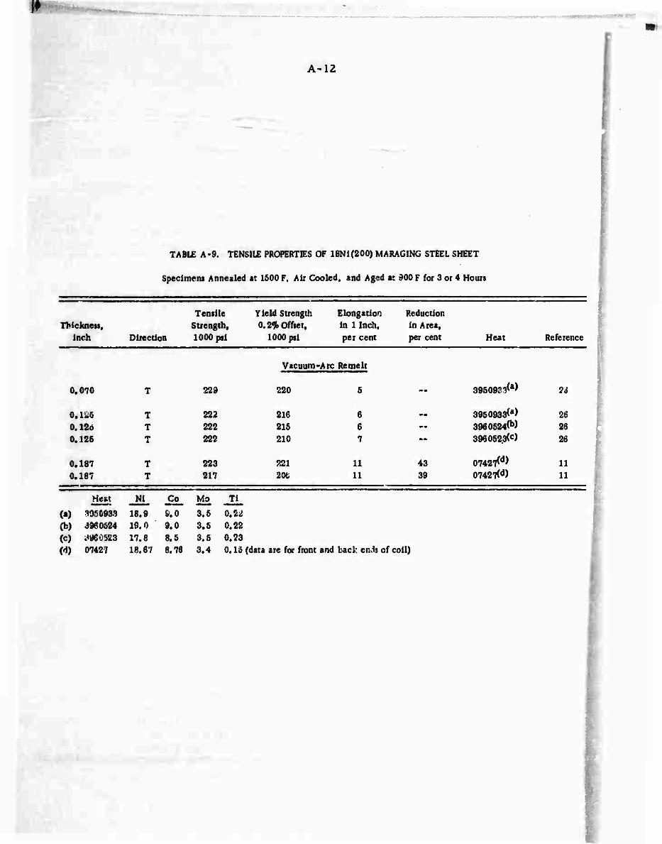
1^
A-12
TABLE A-9. TENSILE PROPERTIES OF 18Ni(200) MARAGING STEEL SHEET
Specimens Annealed at 1500 F, Air Cooled, and Aged at 900 F for 3 or 4 Hours
Thickness. inch Direction
Tensile Strength, 1000 psi
Yield Suength 0.2^ Offset,
1000 psi
Elongation in 1 Inch, per cent
Reduction in Area, per cent Heat Reference
Vacuum-Arc Re melt
0.070 T 229 220 5 •*• 3950933^ ?o
0.K5 0.12o 0.125
I r
222 222 222
216 215 210
6 6 7
— 395093300 3960524(b) 3960523(c)
26 26 26
0.187 0.187
T T
223 217
221 20t)
11 11
43 39
07427M
07427(d) U 11
Heat Ni Co^ Mo Ti
(a) 3950933 18.9 i.O 3.5 0.22 (b) 3960624 19.0 9.0 3.5 0.22 (c) ^960523 17.8 8.5 3.5 0.23 (d) 0742? 18.67 8.76 3.4 0.15 (data are for front and back etuis of coil)

'
A-13
TABLE A-10. TENSILE PROPERTIES OF i8Ni(200) MARAGING STEEL PUTE
Specimens Annealed at 1500 F, Air Cooled, and Aged at 900 F for 3 or 4 Hours
Thickness, inch Direction
Tensile Strength, 1000 psi
Yield Strength 0.2* Offset,
1000 psi
Elongation in 1 Inch, per cent
Reduction in Area, per cent Heat Reference
Air Melt
0.5 0.5 0.6 0.5
1 1 1 1
0.375 0.376 0.376
0.76 0.76
1 1 1
1.25
1.376
1.76 1.76
L T L T
L T L T
T T T
L T
L T T
T
T
L T
246 252 230 236
242 242 236 234
223 227 224
224 225
214 213 204
233
232
230 229
241 245 223 232
234 235 226 226
12.6 9.5 7.6 6.2
10.6 9.5 9.8 7.5
Vacuum-Arc Remelt
219
215 217
211
223
16 16 10
12 10
23(in0.6-) 11.5 12.5
10
9
11 8
56 46 55 46
56 46 47 40
48 43 59
62 47
56 58 61
51
46
60 45
(*) 39
(») 84626(b) 84625(b)
39
s (•) (*) (c) (c)
39 39
s 07427^ 07427(d) 3960528<e)
28 28 26
3950933^) 3950933<f)
26 26
(g) 07427(d) 0742,I<d)
48 28 28
3960524<h> 26
3960523^ 26
3950933<f) 3950933(0
26 26
Heat Ni Co Mo _Ti_
(a) - (10T.) 18.6 7.0 4.5 0.22 (b) 84625 18.6 7.0 4.5 0.22 (c) » (10T.) 18.6 6.9 4.6 0.22 (d) 07427 (15T.) 18.67 8.76 3.4 0.16 (e) 3960526 17.8 8.5 3.5 0.22 (f) 3950933 18.9 9.0 3.5 0.22 (g) -- 18.06 8.6 3.1 0.17 (h) 3960524 19.0 9.0 3.5 0.22 (i) 3960523 17.8 8.5 3.5 0.23
Specimens from Heat 07427 are from front and back ends of plate.,

■ . -
A-14
TABLE A-ll. TENSILE PROPERTIES OF HEAVY SECTIONS OF 18Ni(200) MARAGING STEEL
Specimens Annealed at 1500 F, Air Cooled, and Aged at 900 F for 3 or 4 Hours
Size and Tensile
Shape of Strength, Section Direction 1000 psi
Y ieid Strength Elongation Reduction 0.2%offset, in I Inch, in Are i,
1000 psi per cent per cent Heat Reference
Air Arc Melt
1/2" bar L 243 238 12 55 (a) 39
Bar L 241 238
Vacuum
12
-Arc R^melt
68 (a) 39
4-x4H
r x r T T
230 219
222 201»
7 8
35
38
3950933^)
3950933(b) 26 26
4" x 16" T 228 217 3 40 3960524(c) 26
4" x 1«" T 215 205 9 46 3960523<d> 26
4" x 16" T 210 200 10 50 3960526(e) 26
Heat _N1 _ Co Mo Ti Size of Heat
(a) 18.6 7.0 4.5 0.22 10 tons (b) 3950933 18. 9 9.0 3.5 0.22 -- (c) 3960524 19. 0 9.0 3.5 0.22 -- (d) 3960523 17. 8 8.5 3.6 0.23 -- (e) 3960526 17. 8 8.5 3.5 0.22 --

A-15
TABLE A-12. TENSILE PROPERTIES OF 18Ni(2S0) MARAGING STEEL SHEET
Specimens Anne iled at 1500 F, Air Cooled, and Aged at 900 F for 3 or 4 Hours
Thickness, inch Direction
Tensile Strength, 1000 psi
Yield Strength 0.2% Offset,
1000 psi
Elongation in 1 Inch, per cent
Reduction in Area, per cent Heat Reference
Air Melt
0.025 267 252 3.0 23 mm 49 0.025 260 254 3.0 23 " 49
0.C43 265 256 6.0 38 • • 49 0.043 268 260 5.5 34 — 49
0.074 259 253 8.0 48 -- 49 0.074 263 256 8.0 44 " 49
0.135 272 26a 10 51 — 49 0.135 280 274 10 49 " 49
0.195 0.195
272 281
266 276
4.5 6.0
41 39
A6939(a)
A7035(b) 5 P
Vacuum-Arc Remelt
0.025 246 232 -• - - (c) 50 0.025 252 243 2.6 -- (c) 60
0.040 256 246 3.0 -• 3930575(d) 26
0.050 286 284 4.7 -■ 23832<e> ID
0.063 0.063
271 281
269 276
3.4 (in 2") 3.3(in2")
— 23832<e) 23832<e)
61 51
0.064 254 246 7.3 M (c) 50 0.0C4 254 247 6.0 -- (c) 60 0.064 0.067 •-
262 279
252 274
4.5 3.0 *«•
(0 23664<8)
39 5
0.075 0,075
234 242
230 233
7.8 (in 2") 7.6(in2") ••
24285^ 24285(h)
15 16
0.080 0.080
254 256
245 243
6.0 5.0 mm
3930575(d) 3930b75^d>
26 26
0.090 • - 239 232 11 51 Heat ßW 27
0.100 264 258 4.0 -- 3930553^) 26
0.125 0.125
274 287
270 284
6.2 (in 2") 6.2 (in 2")
-»• 07249(k) 07249<k)
52 52
0.130 278 267 5.0 -- 16815^ 11
0.187 0.187
284 273
282 272
6.0 7.6
26 29
07328 front (m) 07328 back (m)
28 28
0.200 268 262 6.5 -- 3930553^> 26
0.220 258 265 7.0 -- 3930575 71
Footnotes appe ir on following page.

I*
Footnotes for Table A-12;
Heat
(a) A6939(1/2T.) (b) A7035(1/2T.) (c) (d) 3930575 (e) 23832
(f) (g) 23664 (h) 24285 (i) Heat B (J) 3930553 (k) 07249 (1) lc>15 (m) 07328 (15T.)
Nl Co Mo Ti
18.2 7.4 4.7 0.35
18.7 7.6 4.8 0.50
18.57 8.38 4.98 0.43
18.55 7.95 4.72 0.41
18.60 7.74 5.04 0.42
18.75 7.5 4.85 0.43
18.2 8.0 4.8 0.37
18.96 7.34 5.04 0.29
18.4 7.82 4.82 0.36
18.51 7.73 4.9C 0.40
18.45 7.55 4.65 0.51
18.87 7.89 4.90 0.31
A-16
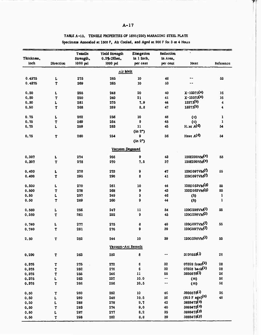
A-17
n TABLE A-13. TENSILE PROPERTIES OF 18Ni(250) MARAGING STEEL PLATE
Specimens Annealed at 1500 F, Air Cooled, and Aged at 900 F for 3 or 4 Hours
Thickness, inch
0.4375 0.4375
0.50 0.50 0.50 0.50
0.75 0.75 0.75
0.75
0.307 0.307
0.400 0.400
0.500 0.500 0.50 0.50
0.560 0.560
0.740 0.740
2.50
0.290
0.375 0.376 0.376 0.376 0.375
0.60 0.60 0.60 0.50 0.50 0.50
Direction
Tensile Strength, 1000 psi
Yield Strength 0.2% Offset,
1000 psi
Elongation in 1 Inch, per cent
Reduction in Area, per cent Heat
L T
L T
L T L T
L T
L T
T T T L T
T L L T L T
275 269
265 260 281 268
262 269 259
260
274 278
278 295
270 278 267 269
266 261
277 281
252
263
276 28S 266 263 266
260 260 288 283
287 293
Air Melt
265
248 240 275
256 264
254
10 10
20 21 7.9 8.8
10 9
11 (in 2")
9 (in 2")
Vacuum Degatted
266 270
273 290
261
260
247
275 276
9 7.6
9 8
10 9 9 9
11 9
8 9
244 10
Vacuum-A re Remelt
262 8
272 276 246 257 266
262 248 278 274 277
6 6
11 10.0 10.5
10 10.6 9.7 9.0 8.2 8.8
46 53
40 41 44 47
48 45 45
36
X-1337l(a) X-1337l(*) 1337 l(b) 1337 l(b)
(c) (c)
Heat A(d)
Heat AC«*)
3CJ30553CJ)
Reference
16 16 4 4
1 1
54
43 37
120E290VM<e) 120E290VM(e)
55
47 41
120G097VM<0 120G097VM(0
55
44 43
120D163VM<0 120D163VM(8)
55 55
46 44
(h) (h)
1 1
54 45
120G298VM(i) 1200298X0^)
55
40 39
120G097W0 120G097VM(0
55
39 120G298VM<i) 55
26
32 07328 front(k) 28 32 07328 backW 28 55 3930575(1) 26 -- (m) 56 -- (m) 56
46 393067^) 26 50 (915 F age/n> 48 42 3888472(0) 40 3888472<0) 39 3888473^?) 39 3888473(P)

A-18
TABLE A-13. (Continued)
Thicknets, inch Direction
Tensile Strength, 1000 pii
Yield Strength 0.2% Offset.
1000 psi
Elongation in 1 Inch, per cent
Reduction in Are«, per cent Heat Reference
Vacuum-Arc Remelt (Continued)
0.50
0.50
0.50 0.50
0.625
1 1
T T
230
236
270 230
261
253 254
223
261
252
251 252
Heat Ni Co Mo Ti
(a) X 13371 17.83 7.41 4.70 0.46 (b) 13371 18.65 8.05 4.90 0.52 (cj* --(20 T.) 18.2 7.9 4.6 0.46 (d) Heat A 17.73 7.40 4.80 0.39 (e) 120E290VM (7 T.) 13.98 8.05 4.90 0.59 (0 120G097VM(7T.) 18.12 7.88 4.77 0.49 (g) 120D163VM (7 T.) 18.04 8.10 4.70 0.50 (h) "(7 1.) 18.0 8.1 4.7 0.£0 (1) 120G298VM (7 T.) 18.25 7.40 4.85 0.17 (j) 3930553 18.4 7.82 4.82 0.36 (k) 07328 (15 T.) 18.87 7.89 4.90 0.31
7.5 (in 1.4H)
6.3 (in 1.4")
13 12
10
8.5 9.5
Heat
56
46
56 55
56
59 46
Nl
18.55 18.35 18.30 18.60 18.80 18.6 18.47
8462^<0
8462rfc0
Heat A(r) Heat G(5)
S930553(i)
07328 fronrfk) 07328 back<k)
25
25
27 27
26
28
Co Mo Ti
(1) 3930775 18.65 7.95 4.72 0.41 (m) -- 18.35 7.80 4.70 0.33 (n) -- 18.30 7.83 4.82 0.35 (o) 3888472 18.60 9.10 5.10 0.62 (p) 3888473 18.80 8.82 4.85 0.65 (q) 84625 18.6 7.0 4.5 0.22 (r) Heat A 18.47 7.54 4.90 0.48 (s) HeatG 18.96 8.43 4.77 0.30
Note: Specimens from Heats 13371, 3888472. and 3888473 were aged at 900 F for 4 hours.

A-19
TABLE A-14. TENSILE PROPERTIES OF HEAVY SECTIONS OF 18Ni(250) MARAGING STEEL
Specimens Annealed at 1500 F, Air Cooled, and Aged at 900 F for 3 or 4 Hours
Tensile Yield Strength Elongation Reduction Strength, 0.2* Offset, in 1 Inch, in Area,
Size and Shape Direction 1000 psi 1000 psi per cent per cent
Ait Melt
1/2" bar L 256 247 -- 64
1-3/4" bar L 267 259 11 58
4" x IB- x 36" L 248 241 10 47 4" x 16" x 36" I "50 242 8.5 40 4" x 16" x 36" ST 241 234 7 30
e* dia. forging L 253 244 — ■ 52
9" dia. forging T 248 238 -• --
9" dia. forging T 240 232 ■ ■ 45
12" dia. forging T 247 239 — 43
14" x 17" WUet L 273 256 4 21 14" x 17" MUet T 276 258 4 18 14" x 17" billet ST 274 257 5 18
10.5" xlO.5" billet T 281 264 8 26 10.5" xlO.5" billet ST 277 260 3 2b
Vacuum-Arc Remelt
5/8" bar L 264 256 12 58 5/8" bar L 263 250 14 59
3/4" bar L 269 265 11 (inl.5-)
S3
3/4- bar L 248 234 14 59
1-bar L 263 256 11 (in 2")
49
1-bar L 263 254 9 42 1- square T 274 270 10 54
1-1/2- RCS L 264 255 11 62
2-1/2" square L 272 266 10 52
1-1/2" x 5" L 278 268 9 48 1-1/2- x 6" T 275 266 8 40
3-1/2" RCS T 263 253 4.6 (inl.5")
21
4" square L 273 265 8.5 40 4" square T 267 258 6.0 29 4" RCS T 266 249 3.5 12
Heat Reference
Induction milf-*)
393057rfb) 393057S(b) 393057rfb)
(c)
Induction melrfd) Ditto
»
Induction meli(d) Ditto
A682^e)
23832(0
06759(0
Heat C(h)
06759(8)
oew-A1)
3960502(0
39605020") 3960502(0
A722rfk)
3960502(0 3960502(J) (16" dia. ingot)
57
1 1 1
57
57 57
57
1 1 1
1 1
5 40
23
27
15
5
26
26 26
23
26 26

A-20
TABLE A-14. (Continued)
Tensile Yield Strength Elongation Reduction Strength, 0.2% Offset, in 1 Inch, in Area.
Size and Shape Direction 1000 psi 1000 psi per cent per cent Heat Reference
Vacuum-Arc Remelt (Continued)
5" iquare L 260 250 10 52 3930553(1) 26 5" square T 259 248 7.5 36 393055a<1) 26
5-1/2" square T(MR) 270 265 7 33 lOlflCm) 17 5-1/2" square T(C) 270 265 6 34 lOlSCm) 17
5-3/4" square L 265 256 12 58 (17- dia. ingot/") 1 5-3/4" square T 270 256 10 46 (17" dia. ingot/n) 1
6" RCS T 272 260 3.5 12 (16" dia. ingot) .- 6" square T(MR) 267 263 5.5 23 1013(0) 17 6" square T(C) 264 261 5.0 28 101J*0) 17 6" square T (bot. MR) 250 245 9.0 52 loietp) 17 6" square T (bot. C) 247 243 9.5 47 lOlfltP) 17 6" square T (top-MR) 248 244 8,7 40 IOI^P) 17 6" square T (top-C) 246 241 9.5 48 ioid(P) 17
7" RCS T 266 249 3.5 12 -- --
7" square L 258 242 7.0 32 Same heat - -
7" square T 257 243 4.5 16 - -
9" square T(bot. MR) 253 248 8.5 41 icnCü 17 9" square T (bot. C) 252 248 8.0 36 lonOO 17 9" square T (top-MR) 246 242 8.0 40 IOITW 17 9" square T (top-C) 250 246 8.0 40 ion(<0 17
10" RCS 271 263 10 44 40059^
11" dia. x7M T 256 242 3 10 -» -•
Heat NI Co Mo Tl Heat Ni Co Mo Ti
(a> --(1/2 T.) 18.45 7.48 4.8 0.48 in 3960502 18.47 6.95 4.83 0.51 (b) 3930675(15 T.) 18.55 7.95 4.73 0.41 (k) A 7225 18.89 7.64 4.96 0.41 (c) 17.6 7.3 4.8 0.50 w 3930553 18.4 7.82 4.82 0.36 (d) --(2.5 T.) 18.32 9.16 5.36 0.52 im) 1015 18.84 8.23 5.07 0.39 (e) A6824(1/2T.) 18.54 7.38 5.34 0.44 (n) --(2. 5T.) 18.34 7.69 5.2 0.45 (0 23832 18.34 7.69 5.2 0.45 (o) 1013 18.86 8.27 5.0 0.41 (g) 06759 18.20 7.22 4.78 0.50 (P) 1016 18.69 7.86 5.0 0.31 (h) HeatC- 18.45 7.46 5.0 0.51 (<0 1017 18.52 7.84 4.82 0.39 (i) 06137(1/2 T.) 18.2 7.6 4.8 0.42 (0 40059(2 T.) 19.1 8.2 4.4 0.40
Note: MR" mid-radius C ■ center.
-

A-21
TABLE A-15. TENSILE PROPERTIES OF 18Ni (300) MA RAGING STEEL SHEET
Specimens Annealed at 1500 F, Air Cooled, and Aged at 900 F for 3 or 4 Hours
Thickness, inch Direction
Tensile Yield Strength Elongatiou Reduction Strength, 0.2% Offset, in 1 Inch, in Area.
1000 psi 1000 psi per cent per cent Hv*.at Reference
0.050 296
Air Melt
282 4
Vacuum-Arc Remelt
0.025 L 267 248 --
0.025 T 283 272 2
0.063 L 284 280 3.0
(in 2") 0.063 T 294 290 2.5
(in 2") 0.064 L 279 271 6 0,064 T 286 278 5
0.065 L 264 261 7.0 (in 2")
0.065 T 268 257 6.8 (in 2")
0.075 L 274 266 7.2 (in 2")
0.075 T 278 271 6.8 (in 2")
0.100 L 301 296 4.8
(In 2")
0.125 L 288 285 4.0 (to 8-)
0.125 T 302 298 3.3
(in 2")
0.130 -- 269 266 1.0
0.140 -- 304 294 5.8 (in 2")
0.140 300 294 4.8 (in 2")
0.195 — 314 308 5
0.200 L 304 299 9.0 (in 2")
0.200 T 301 307 7.8 (in 2")
0.25 -- 322 317 5.2
0.25 -- 296 284 6.4 (in 2")
50
32
30
X-1603(a)
0649
W-24178^
W-24178<e)
..(0
60
(b)
(b)
60
^0
2383ltc) 51
23831<C) 61
(b) (b)
06498(d)
60 50 15
16
16
15
31
0714^0 52
0714^8) 62
He.t^h) 27
(0 44
(ft 44
06269(k) 5
(0 31
(0 SI
(1) (m)
1 44
ootnotes appear on following page.

is-
Footnotes for Table A-15:
Heat Ni
(«) X-1603 18.4 (b) -- 18.72 (c) 23831 18.61
«0 06498 --
(«) W-24178 --
(0 -- 18.67
(8) 07146 18.66 (h) Heat E 18.96
Co Mo Tl
8.8 5.00 0.78 9.08 4.88 0.73 9.05 5.00 0.71
8.92 4.95 0.76 9.09 4.85 0.56 9.13 4.76 0.43
A-22
Heat Ni Co Mo Ti
(i) -- 18. C3 9.00 4.66 0.66
(J) -- 17.80 8.96 4.85 0.63 (k) 06269(1/2 T.) 18.3 9.0 4.8 0.65 (1) -(1/2 T.) 18.27 9.03 4.8 0.65
(m) 18.43 8.71 4.06 0.70

**t 0\
A-23
TABLE A-16. TENSILE PROPERTIES OF 18Ni (300) MARAGING STEEL PLATE
Specimens Annealed at 1500 F, Air Cooled, and Aged at 900 F for 3 or 4 Hours
Thickness. Tensile
Strength, Yield Strength Elongation 0.2% offset. in 1 Inch,
Reduction in Area,
inch Direction lOoC psi 1000 psi per cent per cent Heat Reference
Vacuum-Arc Remelt
0.360 0.360
L T
292 297
289 20 292 18
45 48
23831^ 2383l(•)
47 47
0.375 L 305 297 7.1 - - (b) 56 0.375 T 306 299 6.5 - - (b) 56
0.5 0.5 0.5
L T
290 301 301
274 10 292 7.5 292 7.2
48 40 37
Heat I<c) 0714«<d) 0714rfd)
27 4 4
Heat Ni Co Mo Ti
(a) 23831 18.61 9. 05 5.00 0.71 (b) -- 18.32 9. 06 4.88 0.73 (c) HeatF 18.32 9. 06 4.88 0.73 (d) 07148 18.7 9.30 5.12 0.65
^~

fr-
A-24
TABLE A-n. TENSILE PROPERTIES OF HEAVY SECTIONS OF 18Ni (300) MARAG1NG STEEL
Specimens Annealed at 1500 F, Air Cooled, and Aged at 900 F for 3 or 4 Hours
Size and Shape
5/8" bar
Direction
Tensile Strength, 1000 psi
Yield Strength 0.2ah Offset,
1000 psi
Elongation in 1 Inch, per cent
Reduction in Area, per cent Heat
284
Air Melt
277 Gl
Vacuum-Arc Remelt
Footnotes appear on following page.
(a)
Reference
58
5/8" bar L 289 277 10 48 2383 l(b) 40
3/4" bar V 293 28C 11 (in 1.5")
62 0646l(c) 23
3/4" bar L 295 293 11 67 (d) 1
4" square mm 297 290 7.0 37 (d) 1 4" square L 307 300 6.6 28 07148(e) 4 4" square T 305 296 3.9 18 07148(e) 4 4" square ST 307 300 3.5 17 07148(e) 4 4" square T(MR) 288 283 4.0 19 2037(0 17 4" square T(C) 289 ' 4.6 24 2037(0 17 4" square T(MR) 279 2 7.0 ST 2043(8) 4" square T(C) 282 272 7.0 32 2043(8) 17 4" square T(MR) 29. 287 6.5 32 2036(h) 17 4" square T(C) 290 286 6.5 22 2036(h) 17
4-1/2" square T(MR) 275 270 7.5 37 2046(0 17 4-1/2" square T(C) 272 267 8.5 43 2046(0 17
3-1/2" x 7" bar L 282 272 9.5 24 06989(0 3-1/2" x 7" bar ST 275 261 3.5 8.5 06989(0 18 3-1/2" x 7" bar L 282 271 7.6 26 0708l(k) 18 3-1/2" x 7- bar ST 276 264 2.5 6.0 0708l(k) 18
5" square T (top MR) 287 283 7.7 35 2047(0 17 5" square T (top C) 282 279 8.5 42 2047(0 17 5" square T(bot. MR) 282 277 8.5 35 2047(0 17 5" square T(bot. C) 283 279 7.5 34 2047(0 17
6" square T(MR) 282 278 9.0 42 2046(0 17 T(C) 282 278 9.5 47 2046(0 17
6-1/4" square T (top MR) 276 2'.2 8.7 47 2048(m) 17 6-1/4" square T (top C) 276 270 8.7 44 2048(m) 17 6-1/4" square T(bot. MR) 278 • 273 8.7 46 2048(m) 17 6-1/4" square T(boi. C) 278 272 9.5 44 2048(m) 17
18-1/2" x 2-1/2" T 297 282 7 ae -.00 1 18-1/2" x 2-1/2" ST 292 273 9 26 -(n) 1
_ —
I

A-25
Footnotes for Table A -17:
Mo Heat Ni Co Tl
(a) — 18.5 9.8 4.8 0.6 (b) 23831 18.2 9.05 4.84 0.69 (c) 06461 18.77 8.98 4.88 0.77
(d) — 18.7 8.75 4.9 0.83 (2-1/2 T.)
(e) 07148 18.7 9.30 5.12 0.65
(0 2037 18.79 9.38 4.90 0.58
(g) 2043 1.8.40 8,98 4.98 0.60
(10 2036 18.80 9.30 4.96 0.57
(I) 2046 18.52 9.00 4.86 0.60
0) 06989 18.62 8.74 4.75 0.63
do 07081 18.61 9.14 4.72 0.58
(l) 2047 18.53 9.06 4.95 0.65 (m) 2048 18.47 9.00 4.91 0.58
(n) (2-1/2 T
18.32
.)
9.06 4.88 0.73
Note: Specimens from Heat 07148 aged at 900 F for 4 hours. MR = mid-radius
C = center.
■MBMU
■^w*-

A-26
TABLE A-18. TABULATION OF MINIMUM. MAXIMUM, AND AVERAGE ROOM-TEMPERATURE TENSILE PROPERTIES OF THREE GRADES OF 18 PER CENT NICKEL MARAGING STEELS BY FORM, MELTING PRACTICE, AND TESTING DIRECTION
All Specimens Annealed at 1500 F, Air Cooled, and Aged at 900 F for 3 or 4 Hours
Form
Tensile Strength, 1000 psi
Yield Strength, 1000 psi
Elongation, per cent Number of
Melting Test Over-AU Over-All Over-AU Values(*), Practice Direction Min Max Average Min Max Average Mln Max Average N
Sheet
(200) Grade
VAR T 217 229 223 206 221 215 11 7.5
Plate AM L 230 246 239 223 241 231 7.5 12.5 10 4
Plate AM T 234 252 241 226 245 235 6 9.5 8 4
Plate VAR L 214 230 223 208 225 216 11 12 11.5 3
Plate VAR T 204 233 223 200 228 219 8 16 11.5 9
Heavy sections AM L 241 243 242 238 238 238 12 12 12 2
Heavy sections VAR T 210 230 220 200 229 211 7 10 8.5 5
• (250) Grade
Sheet AM L 257 272 263 252 268 258 3 10 7 4
Sheet AM T 260 281 271 254 276 264 3 10 6 6 Sheet VAR L 204 279 257 230 274 " 250 3 11 6 9 Sheet VAR T 242 287 266 233 284 260 2.5 7.5 5 14
Plate AM L 255 281 266 248 275 259 8 20 12 5 Plate AM T 25^ ,543^ 263 240 265 256 9 21 11.5 5
Plate VD L 255 278 269 247 275 262 8 11 9.5 6 Plate VD T 252 295 273 244 290 266 7.5 10 7.5 7 Plate VAR L 230 288 261 223 278 252 7.5 13 10.5 7 Plate VAR T 236 293 265 232 282 258 6 11 8.5 12
Heavy sections AM L 248 273 259 241 259 249 4 11 8.5 5 Heavy sections AM T 240 275 257 232 »64 246 4 8.5 7 6 Heavy sections AM ST 241 277 264 234 260 250 3 7 5 3 Heavy sections VAR L 248 278 265 234 268 255 7 14 10.5 13 Heavy sections VAR T 246 275 261
(300)
241
Grade
270 252 S 10 7 24
Sheet AM L — .. 296 Ml M 282 — mam 4 1 Sheet VAR L 264 322 290 248 317 283 1 Q 3 14
Sheet VAR T 268 302 287 257 307 282 2 8 5 7
Plate VAR L 290 304 297 272 297 288 7 20 11 4
Plate VAR T 297 306 301 292 299 294 6.5 18 10.5 3
Heavy sections AM L — — 284 mm • •• 277 mm Mi — 1
Heavy sections VAR L 282 307 292 271 300 284 5.5 11 9.0 7
Heavy sections VAR T 272 305 284 267 295 278 4 9.5 7.5 20
Heavy sections VAR ST 275 307 288 ?61 300 275 2.5 9 4.5 4
(a) These values are from Tables A-9 through A-17.
'{ ,
I*

A-27
TABLE A-19. EFFECT OF TEMPERATURE ON THE TENSILE PROPERTIES OF 18 PER CENT NICKEL MARAGING STEEL SHEET
'
TensUe Yield
Test Tensile Yield Strength, per cent
Strength, per cent
Thickness, inch Direction
Temperature, F
Strength, 1000 psi
Strength, 1000 psf
Elongation, per cent
ofRT atrength
of RT yield Heat Reference
(250) Grade
— L RT 262 252 4.5 100 100 M 59 -320 329 315 4.5 125 125
— _. RT 262 252 4.5 100 100 M 39 -320 320 307 4.0 122 122
-- L RT 273 267 __ 100 100 __ 53 -320 333 322 " 122 120.5
— L RT 26" 262 4.2 100 100 ._ 53 -320 3?,7 323 3.0 126 123
T RT 278 274 3.0 100 100 -320 348 336 1.5 125 123
0.036 T RT 250 219 5 100 100 2E-3756^ GO
300 231 197 (inl")
3 92.5 90 600 214 175 3 85.5 80
0.050 T RT 257 235 4 100 100 24285(b) 60
300 236 218 (in 1")
4 92 92.8 600 222 170 4 86.5 72.4
0.063 L RT 271 269 3.4 100 100 23832^c) 51
-100 290 288 (in 2")
3.0 107 107 600 234 227 3.2 86.5 84.4 900 193 183 6.0 71.2 68
0.075 L RT 237 230 7.8 100 100 24285^ 15
-100 253 248 (in 2")
6.8 107 108 -45 250 240 8.0 105.5 104.2 40 239 227 8.0 101 98.7
200 228 221 8.2 96.3 96 300 221 212 7,8 93.3 92.2
0.125 L RT 274 270 5.2 100 100 07319(d) 23
L 300 255 253 (in 2")
5.0 93 93.8 T RT 287 2P4 5.2 100 100 T 300 267 261 5.2 93 92
-^..«te. «4 -

(ä
A-28
TABLE A-19. (Continued)
Thickness, inch Direction
Test Tensile Yield Temperature, Strength, Strength, Elongation,
F 1000 psi 1000 p«i per cent
Tensile Strength, per cent
of RT strength
Yield Strength, per cent
ofRT yield Heat Reference
L
T
0.063
0.065
0.075
0.100
0.125
L T T T T T
L T T
RT -320
RT -320
RT
-100 600 900
RT
-100 -45 40
200 300
RT
-100 -45 40
200 300
79 79
-96 -65 -20 154
RT
300 RT 300
299 362 306 374
284
305 249 213
264
286 278 266 253 249
274
294 285 274 261 255
284 286 310 306 300 278
288
273 302
280
(300) Grade
293 352
301 362
280
302 242
201
251
276 266 253 243 237
266
287 277 265 253 244
280 283 301 300 291 272
285
268 298 273
ao (in 2") 3.0 2.7 7.0
7.0 (in 2") 6.2 6.2 7.0 6.2 6.5
7.2
(in 2") 7.2 7.5 6.8 6.8 6,5
4.0 (in 2") 4.5 3.3 3,9
100 121
100 122
100
107 87.7 75
100
108 105.2 100.7 96 94.4
100
107 104 100 95.2 93
100 100 108.3 107 105 97.2
100
94.8 100 92.7
100 120 100 120
100
108 86.5 71.8
lOo
110 106 100.8 97 94.5
100
108 104 99.6 95 91.8
100 100 106.3 106 103 96.2
100
94 100 91.5
53
23831 (e) 51
06498' (0 15
W-24178^ 15
Heat EC1) 12
07146^ 23
Heat Treatment: Annealed at 1500 F, air cooled, and aged at 1500 F for 3 or 4 hours.
Heat Ni Co Mo Ti (0 06498 (VAR) (g) W-B4178(VAR) (h) HeatE 18.7 10.03 5.00 0.76 (i) 07146 (VAR) 18.66 9.09 4.85 0.56
Heat Ni Co Mo Ti (a) 2E-3756 (AM) 18.40 7.76 4.78 0.36 (b) 24285 (VAR) 18.32 7.45 4.82 0.39 (c) 23832 (VAR) 18.60 7.74 5.04 0.42 (d) 07249 (VAR) 18.51 7.73 4.90 0.40 (e) 23831 (VAR) 18.61 9.05 5.00 0.7?
I . ■

TAB
LE A
-20.
E
FFEC
T O
F TE
MPE
RA
TUR
E O
N T
HE T
ENSI
LE P
RO
PER
TIES
OF
PLA
TE A
ND B
AR
STO
CK O
F 18
PER
CE
NT N
ICK
EL M
AR
AG
ING S
TEEL
S
Size
and
Fo
rm
Pla
te
Bar
5/8"
bar
3/4"
bar
Ten
sUe
Yie
ld
Str
engt
h,
Str
engt
h.
Tci
t T
ensU
e Y
ield
R
educ
tion
pe
r ce
nt
per
cen
t
Tem
per
atu
re,
Stre
ngth
, S
tren
gth
, E
lon
gati
on,
in A
rea,
of
RT
ofR
T
Dir
ecti
on
F 10
00 p
si
1000
psi
p
er c
ent
per
cen
t st
reng
th
yiel
d
(250
) G
rad
e
L R
T
244
233
12
57
100
100
L -3
20
305
291
9 40
12
5 12
5 T
R
T 24
3 23
2 10
44
10
0 10
0 T
-3
20
310
292
7.3
29
12
7.5
126
L R
T 26
3 25
4 11
56
10
0 10
0 60
0 24
4 23
4 11
.5
56
93
92
.2
700
235
224
12
56
89.3
88
.2
800
227
211
13.5
58
8
6.5
8
3.0
90
0 20
7 19
2 16
.5
65
78.8
7
5.7
95
0 19
1 17
7 21
71
72.7
6
9.7
10
00
166
150
23
73
63
.2
59
L R
T 26
0 25
1 11
56
10
0 10
0 60
0 22
6 21
2 11
56
87
84
.5
700
223
206
12
56
85
.8
82.2
80
0 21
0 19
2 1
3.5
56
80.8
76
.5
900
197
175
14
.5
62
75.8
69
.7
950
182
164
16
66
70
65
.4
1000
15
6 14
0 20
73
60
5
5.8
L R
T 26
2 25
0 13
.5
58.5
10
0 10
0 30
0 23
8 22
2 —
--
91
89
60
0 22
2 21
0 --
--
84.8
84
80
0 20
9 18
8 --
--
7
9.8
75
.2
1000
18
4 16
2 —
--
7
0.3
65
L R
T 26
9 26
5 10
.9
52
.8
100
iOO
-1
00
289
280
10
.7
52.0
10
7.3
lüo.6
60
0 23
3 22
1 10
.9
52.7
8
6.8
8
3.4
90
0 20
0 18
4 15
.9
60.5
74.5
6
9.5
Hea
t R
efer
ence
59
53
>
i M
53
23832^
40
0675
9(b
) 23

TABL
E A
-20.
(C
onti
nued
)
Size
and
Fo
rm
Dir
ecti
on
Te$
t T
empe
ratu
re,
F
Ten
sile
St
reng
th,
1000
psi
Yie
ld
Stre
ngth
, 10
00 p
si
Elo
ngat
ion,
pe
r ce
nt
Red
uctio
n in
Are
a,
per
cent
Tei
uil
e St
reng
th,
per
cent
of
RT
stre
ngth
Yie
ld
Stre
ngth
, pe
r ce
nt
of R
T yi
eld
Hea
t R
efer
ence
l-b
ar
(250
) G
rade
(C
onti
nued
)
RT
263
256
11.0
49
.2
100
100
•100
28
1 27
4 9.
5 44
.8
107
107
-45
271
262
10.8
46
.4
103
102.
3 40
26
4 25
8 11
.0
48.8
10
0.3
100.
7 20
0 25
5 24
7 11
.2
50.4
97
96
.5
300
245
237
(300
)
11.5
Gra
de
50.8
93
.2
92.7
0675
9(b
) 15
Bar
RT
300
500
600
mo
800
900
1000
295
272
263
257
250
241
214
180
293
267
254
247
237
230
199
168
11
10
10
10 9 12
15
57
38
66
56
54
57
37
79
100 92
.2
89.2
87
.2
84.8
81
9 72
.5
61.0
100 91
.2
86.8
84
.3
81.0
78
.5
68.0
57
.3
>
i
Bar
5/8"
bar
RT
600
700
800
900
950
1000
RT
300
600
800
900
1000
288
250
246
240
216
196
16ö
289
266
247
235
210
206
282
240
236
223
203
181
155
277
246
236
222
198
192
12.
12,
12.
14.
17.
22.
24.0
10.0
62
62
62
61
68
76
77
48
100
86.8
85.5
83.3
75.0
68.0
57.3
100
92.0
85.5
81.3
72.7
71.4
100 85.2
83.7
79.0
72.0
64.2
55.0
100
88.8
85.2
80.2
71.5
69.3
53
2383
1<c)
40

• •
TABL
E A
-20.
(C
onti
nued
)
Size
and
Fo
rm
Dir
ecti
on
Ten
T
empe
ratu
re,
F
Ten
sile
St
reng
th,
1000
pii
Yie
ld
Stre
ngth
, 10
00 p
ii E
long
atio
n,
per
cent
Red
uctio
n in
Are
a,
per
cent
(300
) G
rade
(C
ontin
ued)
3/4"
bar
3/4"
bar
3.5"
x 7
" ba
r
3.5"
x 7
" ba
r
RT
-100
60
0 90
0 70
300
500
800
900
1000
RT
350
650
700
900
RT
350
650
700
800
293
314
245
217
300
272
259
24.:
231
203
281
258
236
239
226
259
243
241
286
306
230
200
281
251
235
218
205
186
272
229
219
218
204
272
229
228
226
214
11.2
10
.7
10.9
16
.2
8 9 10
12
16
52.5
51
.2
51.0
58
.8
23
32
40
41
49
60
Ten
iile
Stre
ngth
, pe
r ce
nt
of R
T st
reng
th
100
107 83
.7
74.0
100 90
.7
86.5
80
.3
77.0
67
.7
100 92
.0
84.0
85
.0
80.5
100 92
.0
86.2
85
.5
82.6
YK
ld
Stre
ngth
, pe
r ce
nt
ofR
T
yiel
d
100
107 80
.5
70.0
100 89
.3
83.7
77
.6
73.0
66
.2
100 84
.2
80.5
80
.2
75.0
100 84
.2
83.8
83
.2
78.8
Hea
t tr
eatm
ent:
Ann
eale
d at 1
500
F, a
ir c
oole
d,
and
aged
at
900
F fo
r 3
or 4
hou
rs e
xcep
t as
not
ed.
Hea
t N
i C
o M
o T
i
(a)
2383
2 (V
AR
) 18
.34
7.69
5.
2 0.
45
(b) 0
6759
(V
AR
) 18
.20
7.22
4.
78
0.50
(c
) 2
3831
(V
AR
) 18
.61
9.05
5.
00
0.71
(d
) 0
6461
(V
AR
) 18
.77
8.98
4.
84
0.77
(e
) La
b in
duct
ion
15.2
9.
2 5.
1 0.
70 (
18U
0 F
, ai
r co
ol,
900
F 3
hr)
mel
t (f
)
0698
9 (V
AR
) .8
.62
8.74
4.
75
0.63
(g) 0
7081
(V
AR
) 18
.61
9.14
4.
72
0.58
V
AR -
Vac
uum
-arc
rem
elt.
Hea
t R
efer
ence
0646
1' (d
) 23
32<e
) 22
0698
9 (0
21
>
I
0708
1(0
21
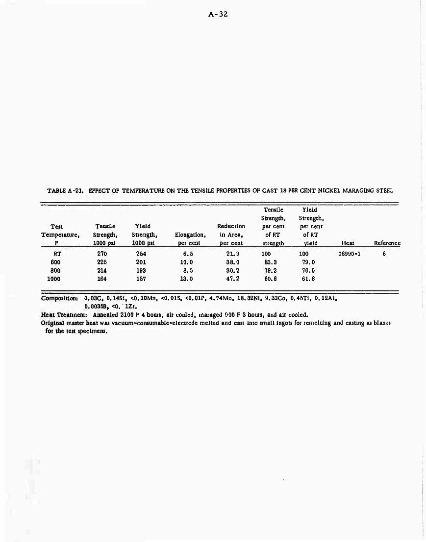
A-32
TABLE A-21. EFFECT OF TEMPERATURE ON THE TENSILE PROPERTIES OF CAST 18 PER CENT NICKEL MARAGING STEEL
Ten Temperature,
F
Tensile Strength, 1000 psl
Yield Strength, 1000 pit
Elongation, per cent
Reduction in Area, per cent
Tensile Strength, per cent of RT
strength
Yield Strength, pet cent
of RT yield Heat Reference
RT 600 800
1000
270 225 214 164
254 201 193 157
6.5 10.0 8.5
13.0
21.9 38.0 30.2 47.2
100 83.3 79.2 60.8
100 79.0 76.0 61.8
06990-1
Composition: 0.03C, 0.14Sit ^.lOMn, <0.01S, <0.01P, 4.74Mo, 18.32Ni, 9.33Co, 0.45Ti, 0.12A1, 0.0035B, <0. IZr.
Heat Treatment: Annealed 2100 F 4 hours, air cooled, maraged '.00 F 3 hours, and air cooled. Original master heat was vacuum-consumable-electrode melted and cast into small ingots for remelting and casting as blanks
for the test specimens.

A-33
TABLE A-22. EFFECT OF TEMPERATURE ON THE ELASTIC MODULUS OF THE 18 PER CENT NICKEL MARAGING STEELS
Specimens Annealed at 1500 F, Air Cooled, and Aged at 900 F for 3 or 4 Hours
Size Elastic and Temperature. Modulus.
Shape Grade F . Direction p«i x 106 Heat Reference
0.125" sheet 250 RT 300 RT 300
26.6 26.0 27.4 26.5
07249(a) 52
Plate 250 RT RT
26.5 26.5
— 20
Bar 250 RT 600 ' 800 900
1000
26.5 22.1 22.0 19.0 18.7
53
Bar 250 RT 600 800 900 950
1000
26.5 22.3 22.0 20.1 19.3 19.1
53
0.125" sheet
i
300 RT 300 RT 300
27.2 25.9 28.0 27.5
07146(b) 52
0.140" sheet 300 RT • ■ 26.8 Heat l(c) 44 0.U0" sheet 300 RT — 26.6 Heat 2(d) 44 0.250" plate 300 IT - - 26.4 Heat A(e) 44
Bar 300 RT 600 800 900
L L L L
27.5 22.9 22.1 20.1
"
53
1000 L 19.4
3-1/2" x 7" bar 300 RT 650 RT 650
L L
L(comp.) L(comp.)
26.5 24.0 28.3 25.7
18
Heat Ni Co Mo Ti
(a) 07249 (VAR) 18.51 7.73 4.90 0.40 (b) 07146 (VAR) 18.66 9.09 4.85 0.56 (c) Heat 1 (VAR) 18.63 9.00 4.66 0.66 (d) Heat 2 (VAR) 17.80 8.96 4.85 0.63 (e) Heat A (VAR) 18.43 8.71 4.06 0.70

A-34
TABLE A-23. EFFECT OF TEMPERATURE ON THE COMPRESSIVE.
Compressive Shear Compienlve Yield. Strength,
Size Yield per cent Shear per cent and Temperature, S.rength, ofRT Strength, of RT
Shape Grade
250
F Direction 1000 psi Yield 1000 pti Strength
Sheet RT -•- 247 -- 143 -- Sheet 300 RT T 296 - -
Plate
Bar
250
Bar
RT
RT 350 650 800
RT 350 65C 800
247
241
289 262 244
100 90 84
100 90.6 84.6 80.3
143 143
163
133 124
163
139 125
100
81.5 76
100
85.2 76.7
Heat (a) 06989(VAR) (b) C7081(VAR)
Ni 18.62 18.61
Co 8.74 9.14
Mo 4.75 4.72
Ti 0.63 0.58
Heat treatment: Annealed at 1500 F, air cooled, and aged at900 F for 3 or 4 hours.

A-35
SHEAR. AND BEARING PROPERTIES OF THE 13 PER CENT NICKEL MARAGING STEELS
Bearing (e/ D= 1.5) Bearing (e/ D = 2.0) Bearing Strength, Bearing Yield. Bearing Strength, Bearing Yield.
Ullimaf- per cent Yield per cent Ultimate per cent Yield per cent Strength, ofRT Strength, ofRT Strength. ofRT Strength, ofRT 1000 psi Strength 1000 psi Yield 1000 psi Strength 1000 psi Yield Heat Reference
23832 1
19
20
391 100 382 100 500 100 474 100 0698 B^
339 86.7 331 86.7 436 87.2 401 84.7 326 83.4 319 83.5 421 84.2 396 83.4
402 100 372 100 513 100 431 100 070S11 (b) 21
344 85.5 330 88.6 449 87.5 391 90.8 328 81.5 318 85.5 440 85.8 384 89

A-36
TABLE A-24. EFFECT OF ELEVATED-TEMPERATURE EXPOSURE ON THE ROOM-TEMPERATURE TENSILE PROPERTIES OF 18 PERCENT NICKEL MARAGING STEELS
Size and
Shape Grade
Exposuie Exposure Tensile Yield Reduction Temperature, Time, Strength, Strength, Elongation, in Area,
F hours Direction 1000 psi 1000 psi per cent per cent Heat Reference
0.025" sheet 250
0.050" sheet 250
0.035" sheet 300
3.5" xT'bar 300
None -- T 600 250 T 600(*) 250 T
300 5 T 300 50 T 400 5 T 400 50 T 500 5 T 500 50 T 600 5 T 600 50 T 700 5 T 700 50 T
None -- T 600 250 T 600(8) 250 T
None -- I. 650 500 L 650 1000 L 800 500 L 800 1000 L
230 228 1.5 .. 238 237 1.2 mm
255 -- 1.2 --
267 256 3.5 ..
268 259 3.5 -- 269 260 3.0 -. *67 259 3.5 -- 268 260 2.5 -- 267 259 3.0 -- 269 261 3.0 -- 271 263 3.0 -- 273 263 2.5 • . 281 274 3.0 --
288 283 2.5 289 284 2.0 -- 297 293 1.5 --
282 272 8.5 24.8 293 287 5.6 22.2 297 291 4.8 16.6 309 298 3.6 13.8 307 302 3.6 9.8
Heat Treatment
23560(b) 13
3960502{c) 60
H-23847(d) 13
07081^ 18
(a) Specimens stressed at 150,000 psi during exposure. Heat Ni Co Mo Ti
(b) 26560(VAR) 18.72 7.87 4.59 0.24 (c) 3960502(AM) 18.48 7.00 4.84 0.50 (d) H-23847(VAR) 18.32 9.06 4.88 0.73 (e) 07081(VAR) 18.61 9.14 4.72 0.58
Aged at 900 F for 3 hours before exposure Aged at 900 F for 4 hours before exposure Aged at 900 F for 3 hours before exposure Aged at 900 F for 3 hours before exposure
There was no effect of exposure at 500 F for 1000 hours for Heat 07081.

A-37
TABLE A-25. CIIARPY IMPACT PROPERTIES OF 18 PER CENT NICKEL MARAGING STEEL PLATE
Standard V-Notch Charpy Specimens Annealed at 1500 F, Air Cooled, and Aged at 900 F for 3 Hours
Plate Test Impact Thickness, Temperature, Energy,
in. Direction F ft-lb Heat Reference
0.400 L RT 28 2356o(a) 16
0.5 L RT 26 W24059tb) 24 L L L L L L T T T T T T T
0.5 L RT 24 59 L L L L L T
0.5 T RT 84625(c) 25 T T T T T T
0.5 L RT 23 (Air melt) L L L L L L
18Ni (2C 10) G; rade
RT 28
RT 26 212 26 40 25 0 25
-40 23 -100 21 -320 18 RT 19 212 20 40 18 0 18
-40 16 -100 14 -320 12
18Ni (250) G: rade
RT 24 0 24
-100 21 -175 21 -244 20 -320 20 RT 18
RT 18 750 20 500 19 250 19 -40 18
-180 16 -320 13
RT 23 0 23
-100 21 -175 21 -244 20 -320 20 -420 16

A-38
TABLE A-25. (Continued)
Plate Test Impact Thickness, Temperature, Energy,
in. Direction F ft-lb Heat Refe rence
18Ni (260) Grade (Continued)
0.5 L -40 14.7 Heat A(d) Z7
0.5 L RT 13-24 120D163VM(e) r-5 T RT 13-19 T 300 17 T 200 17 T 150 14 T 125 14 T 75 16 T C 16 T -40 16 T -65 18 T -100 17 T -150 14 T -200 14 T -320 12 L* RT 17-19 T* RT ' 13-18
0.560 L RT 21-24 120G298VM(f) 55 T RT 16-18
0.625 L(A) RT 24 3930553^8) 26 L(A) -40 22 L(A) -100 24 L{A) -320 17 MB) RT 31 L(B) -40 27 L(^ -100 26 UT3) -320 21
0.625 — RT -40
-100 -320
17 17 14 12
3930502(h) 26
0.740 L RT 12-14 120G097VM(i) 55 T RT 11-13
1.625 L+ T RT
IBNi (300)
14.5-16.5
Grade
X14637^ 47
0.5 L -40 14.9 HeatF^) Z7
Footnotes appear on following page.

A-39
Footnotes for Table A-25:
Heat Ni Co Mo Ti
(a) 23560 (VAR) 18.72 7.87 4.59 0.24
(b) W24059 18.19 8.53 3.36 0.08
(c) 84625 (VAR) 18.9 8.43 4.77 0.30
(d) Heat A 18.47 7.54 4.90 0.48 (e) 120D163VM (VAR) 18.04 8.10 4.70 0.50
(0 120G298VM (VAR) 18.25 7.40 4.85 0.17
(g) 3930553 (VAR) 18.40 7.82 4.82 0.36 (h) 3930502 (VAR) 18.47 6.95 4.83 0.51 (i) 120G097VM (VAR) 18.12 7.88 4.77 0.49 (j) X14637 Not reported Aged 915 F 4 hours (k) Heat F (VAR) 18.32 9.06 4.88 0.73
VAR - Vacuum-arc remelted; AM - air melt. (A) From 'op of ingot; (B) from bottom of ingot. •As rolled and aged at 900 F for 3 hours.

A-40
TABLE A-26. CHARPY IMPACT PROPERTIES OF 18 PER CENT NICKEL MARAGING STEELS AS BARS, FORCINGS, AND BILLETS
Standard V-Notch Charpy Specimens Annealed at 1500 F, Air Cooled and Aged at 900 F for 3 Hours Except as Noted
Test Impact Size Temperature, Energy,
and Shape Direction F ft-lb Heat Reference
18Ni (250) Grade 1/2" sq bar L RT 20 (Air Melted) 1
L 1100 56 L 900 34 L 600 34 L 300 35 L -40 19 L -65 19 L -100 18 L -320 13
5/8" dia. bar L RT 28 23832(a) 40 L -100 27 L -320 14
3/4" dia. bar L RT 30 Heat C(b) 27
3/4" dia. bar L RT 16 06759<c) 23 L -100 17
1.5" x 5" forging L RT
-40 -100 -320
12 12 10 8
3930502^) 26
5" sq billet L(A) RT 28 (VAR) 26 L(A) -40 28 L(A) -100 27 L(A) -320 20 L(B) RT 28 MB) -40 27 MB) -320 19
18Ni (300) Grade
1/2" sqbar L L L
RT 1100 900
17 44 24
(VAR) 1
L 600 28 L 300 30
- - -tr- - -40 17 L -65 16 L -100 15

A-41
TABLE A-26 (Continued)
Test Impact Size Temperature, Energy,
and Shape Direct! on F ft-lb Heat Reference
18Ni (300) Grade (Continued)
1/2" sqbar L -320 11
Bar RT -320
22-25 12-14
59
5/8" dia. bar L L L
RT -100 -320
28 27 15
23831<e) 40
3/4" dia. bar L L
RT -100
19 21
0646 l(f) 23
Dome forging Tangential 70 11 C-40148(g) 14 Radial 70 13 Tangential -100 9
Heat (a) 23832 (VAR)
Ni 18.34
Co
7.69
Mo
5.20
Ti
0.48 (b) Heat C 18.45 7.46 5.0 0.51 (c) 06759 (VAR) 18.20 7.22 4.78 0.50 (d)3930502 18.47 6.95 4.83 0.51 (e) 23831 (VAR) 18.20 9.05 4.84 0.69 (0 06461 (VAR) 18.77 8.98 4.88 0.77 (g) C-40148 19.08 8.59 4.80 0.60
VAR-vacuum-arc remelted. (A) From top of ingot; (B) from bottom of ingot, •Hot rolled and aged at 900 F.

A-4Z
TABLE A-27. CHARPY IMPACT PROPERTIES OF CAST 18 NICKEL M -RAGING STEALS
Specimens - Standard V-Notch Charpy
Casting Thickness,
Grade inches
220
250
230
240
250
230
Meltine Practice*3) Heat Treatment
Test Temp,
F
Impact Energy,
ft-lb Heat
AM
VD
VD
VD
AM
1800 F 4 hr, 900 F 3 lir 2000 F 4 hr, 900 F 3 hr 2200 F 4 hr, 900 F 3 hr
2100 F 4 hr, 900 F 3 ht
2100 F 4 hr, 900 F 3 hr
2000 F 4 hr, AC, 900 F 3 hr
2100 F 4 hr, AC, 900 F 3 hr
250
240 1-in. keel block IM argon atmos. 2100 F 4 hr. 900 F 3 hr
-40 -40 -40
70 -40
70 -40
70 -40
70 -40
70 -40
70 -40
70 -40
70 -40
RT
11 62-029^
17 u
16 62-214vC)
13
13 62-393^) 12
12 62-282(eJ
10
17 62-227(f)
17
10 62-393 8 •
16 62-227 14
10 62-393 8
16 62-227 10
17
(a) AM - air melted; VD ■ vacuum degassed; IM - induction melted.
Heat Ni Co Mo Ti
(b) 62-029 16.60 10.35 4.60 0.27
(c) 62-214 16.89 10.30 4.75 0.36
(<J) 62-393 17.15 10.40 4.77 0.33
(e) 62-282 17.18 10.40 4.62 0.41
(f) 62-227 17.21 10.47 4.72 0.37
(g) 39 16.92 10.40 4.72 0.38
39(8)
Reference
|]
Cl
61
61
61
SI
61
61
61
62

A-43
TABLE A-28. RESULTS OF PRECRACKED CHARPY IMPACT TESTS ON 18 PER CENT NICKEL MARAGING STEEL PUTE
Precracked V-Notch Charpy Specimens
Plate Thickness,
in. Aging
Tieatment Direction
Test Temperature,
F
Impact Energy,
W/A -in, -lb/in.2 Heat Reference
1/2
1/2
1/2
1/2
875F 18hr
900 F 4 hr
875 F 8 hr
875 F 8 hr
L L L L L T T T T T
L T
L T
18Ni (200) Grade
RT 1130
18Ni (250) Grade
RT 3G6 400 584 200 460 0 303
-100 90 RT 353 400 514 200 401 0 238
-100 123
RT 353 RT 442
RT 228 RT 212
28889^
ItCDIfl^
120D298(C)
120G097(dJ
Heat Ni
(a) 28889 (VD) 18.00 (b) 120D163(VD) 18.60 (c) 120D298 (d) 120G097(VD) 18.12
Co Mo
8.51 3.30 8.00 4.95
Not reported 7. 88 4.77
Ti
0.19 0.48
0.49

A-44
TABLE A -29. TENSILE DATA FROM EDGE-NOTCHED SHEET SPECIMEK., OF 18 PER GENT NICKEL MARAGING STEtLS
Data are for Edge-Notched Specimens With Notch Root Radii of 0.001 Inch or LMI
Specimen Test Notched ~" *' ' " "a =S3Z=
Thlckoejs, Width, Temperature, Strength, NS/YS NS/TS in. Preliminary Treatments in. F Direction 1000 psi Ratio Ratio Heat Reference
18Ni (250) Grade
0.025 1500 F, AC, 900 F 3 hr 1 RT T 209 0.92 0.91 23560^) 13 1500 F, AC. 900 F 3 hr 1 -65 T 215 0.99 0.97 1500 F, AC, 900 F 3 hr 1 600 T 170 0.91 0.88 900 F 3 hi + 600 F 250 hr 1 RT T 206 0.915 0.89
'.
0.028 900 F 4 hr 1 RT T 195 mm 0.78 2E-3750(b) 60
0.036 900 F 3 hr 1 70 T 219 .. 0.875 2E-3760(b) 60 300 T 197 -- 0.85
1 600 T 175 • - 0.82
0.050 900 F 4 hr 1 RT T 235 0.91 0.89 3960502<c) GO
0.050 900 F 3 hr 1 70 T 235 .. 0.915 2428rfd) GO 300 T 216 -- 0.925 600 T 170 •■ 0.77
0.050 1500 F. AC, 900 F 3 hr (Kt = 15) RT T 251 0.87 0,86 23832(e) 19
0.063 1500 F. AC, 900 F 3 hr (Kt > 15) RT L 226 0.84 0.835 23832<e) 51 RT T 193 0.70 0.69
-150 L 229 — -- -150 T 200 ■ • --
0.125 As rolled + 900 F 3 hr (Kt > 16) RT L 155 0.575 0.565 07249(0 52 RT T 177 0.626 0.62
300 L 174 0.69 0.68 300 T 154 0.59 0.58
mm 2070 GW + 900 F 3 hr 2 RT L 236 0.85 » -- 5 2 RT T 167 0.58 —
30%CW +900 F3hr 2 RT L 210 0,71 -- 2 RT T 139 0.46 —
40%CW + 900F3hr 2 RT L 212 0.72 — 2 RT r 114 0.37 --
50%CW + 900F3hr 2 RT L 188 0.60 »m
2 RT T 98 0.30 — 70%CW + 900F3hr 2 RT L 157 0.51 —
RT T 104 0.32 --
18N1 (300) Grade
0.035 1500F. AC, 900F3hr 1 RT T 210 0.74 0.73 H-23847(8) 13 1500 F, AC, 900F3hr 1 -65 T 202 0.715 0.70 1500 F, AC, 900F3hr 1 600 T 169 0.69 0.66 900 F 3 hr, 600 F 250 hr 1 RT T 207 0.73 0.72

A-43
TABLE A-29. (Continued)
#'
Specimen Test Notched Thickness, Width, Temperature, Strength, NS/YS NS/TS _Jn. Preliminary Treatments in. F Direction 1000 psi Ratio Ratio Heat
0,100
18Ni (300) Grade (Continued)
0. 063 1500 F, AC, 900 F 3 hr (Kt> 15)
1500 F, AC, 900F3hr
0.115 90C F 3 hr 2 1500 F, AC. 900 F3hr 2 30<5(>CW + 9OO F 3hr 2 50<5'oCW + 90O F 3hr 2
0.116 900 F 3 hr 2 1500 F, AC, 900F3hr 2 3070CW, 900 F 3hr 2 50<5'oCW, 900 F 3hr 2
0.125 As rolled + 900 F 3 hr (Kt > 16)
(a) (b) (c)
(d) (e)
(0 (g) (h) (1) (j) (k) (1)
20</oCW + 900 F 3hr 30<7«CW + 9OO F 3hr
40%CVf + 900 F 3hr
50% CW + 900 F 3hr
70%CW + 900 F 3hr
2
2
2
I 2
2
2
2
2
Heat
23560 (VAR) 2E-3756(AM) 3960502 (AM) 24285 (VAR) 23832 (VAR) 07249 (VAR) H-23847 (VAR) 23831 (VAR) Heat E 7C056 7C057 07146 (VAR)
Ni
RT RT
-100 -100
RT RT -96 -65 -20 154
RT RT RT RT
RT RT RT RT
RT
RT 300 300
RT RT RT RT RT RT RT
Co Mo
18.72 7.87 4.59 18,40 7.76 4.78 18.48 7.00 4.84 18.32 7.45 4.82 18.6 7.74 5.04 18.61 7.73 4.90 18.32 9.06 4.88 18.61 9.05 5.00 18.7 10.03 6.00 On low side of composition range. On high side of composition range. 18.66 9.09 4.85
L T L T
L T T T T T
L T
T L T
Ti
0.24 0.36 0.50 0.39 0.42 0.40 0.73 0.71 0.76
0.56
214 178 204 176
276 230 243 214
236 236
217 209
215 166
162 138 132
133
137 114 129 125
204 190 106 141 95 114 81
132 80
0.765 0.755 2383l(h) 0.615 0.605 0.68 0.67
0.99 0.815 0.80 0.715 0.81 0.87
0.82 0,79 0.75 0.55
0.53 0.45 0.41 0.39
0.48 0.38 0.48 0.46
0.65 0.58 0.32 0.43 0.28 0.33 0.23 0.39 0.23
Reference
51
0.98 0.805 0.785 0.70 0.79 0.85
0.80 0.78 0.74 0.55
0.52 0,44 0.40 0.39
0.475 0.38 0,475 0.445
Heat rf1) 12
7C05^J)
7C057(k)
07146<1> 52

A-46
TABLE A-30. TENSILE DATA FROM CENTER-NOTCHED SHEET SPECIMENS OF 18 PER CENT NICKEL MARAG1NG STEELS
Specimen Test Notched Thickness. Width. Temperature, Strength, NS/YS NS/TS
in. in. F Direction 1000 psi Ratio Ratio Heat Reference
18Ni (250) Grade
0.078 1.75 RT L 209 0.91 0.88 24285(a) 15
RT T 184 0.79 0.76 -100 L 218 0.88 0.86 -48 L 214 0.86 0.815
40 L 206 0.905 0.86 200 L 200 0.905 0.88
300 L 184 0.87 0.835
0.080 M m RT T(A) 280 0.98 0.96 3930553(b) 26 RT T(B) 266 1.02 1.00
0.125 3.0 RT L 160 0.59 0.5H& 07249(c) 52 RT T 153 0.54 0.53 300 L 185 0.615 0.61 300 T 146 0.66 0.545
0.177 • - RT L(A) 255 -- -- 3930553(b) 26 0.175 RT T(A) 248 0.98 0.93 0.176 RT 10) 276 -- —
0.177 RT T(B) 253 0.97 0.94
0.180 -- RT T 274 1.08 1.06 3930575(d) 26
18Ni (300) Grade
0.065 1.75 RT L 188 0.738 0.70 06498(e) 15
RT T 186 0.728 0.695 -100 L 192 0.698 0,67 -48 L 195 0.73 0.70 40 L 192 0.76 0.72
200 L 182 0.75 0.72 ** 300 L 178 0.75 0.715
0.075 1.75 RT L 178 0.665 0.65 W-24178(0 15 RT T 165 0.61 0.59
-100 L 178 0.62 0,605 -46 L 177 0.64 0.62 40 L 166 0.625 0.605
200 L 172 0.68 0.66 300 L 172 0.71 0.676
0.125 3 RT L 142 0.50 0.495 07146(8) 62
RT T 121 0.105 0.40 300 L 138 0.515 0.508 300 T 119 0.435 0.428
0.140 2.25 RT -- 193 0.655 0.638 Heat l(h) 44
0.140 2.28 RT -- 148 0.495 0.485 Heat 2(i) 44
0.180 3 -66 ST 70 0.26 0.25 (From 4■■ x ^ billet) 37
Footnotes appear on following page.

Footnotes for Table A-30:
A-47
Heat Ni
(a) 24285 (VAR) (b) 3930553 (VAR) (c) 07249 (VAR) (d) 3930575 (VAR) (e) 06498 (VAR) (0 W-24178 (VAR) (g) 07146 (VAR) (h) Heat 3 (VAR) (i) Heat 2 (VAR)
18.32 18.40 18.Cl 18.55 18.36 18.69 18.66 18.63 17.80
_Co^ Mc Ti
7.46 4.82 0.39 7.82 4.82 0.36 7.73 4.90 0.40 As-rolled + 900 F 3 hr 7.95 4.72 0,41 9.10 4.93 0.60 8.90 4.92 0.62 9.09 4.85 0.56 As-rolled + 900 F 3 hr 9.00 4.66 0.66 8.96 4.85 0.63
Data are for center-notched specimens with fatigue cracks at the ends of the notches. 1500 F, air cooled, and aged at 900 F 3 hours except as noted.
VAR - Vacuum-arc remelted; ST - short transverse direction. (A) From top of ingot; (B) from bottom of ingot.
All specimens annealed at
_.

A-48
TABLE A-31. TENSILE DATA FROM PART-THROUGH FATIGUE-CRACKED SPECIMENS OF SHEET AND PLATE OF 18 PER CENT NICKEL MARAGING STEELS
Thickness, in.
0.109
Specimen Width,
in.
Fatigue Crack
1.5
Length, in.
Depth, in.
Area, sq in.
Notched Specimen Strength, Direction 1000 psi
NS/YS NS/TS Ratio Ratio Heat Reference
0.22 0.29 0.34
(2C. 2%) (32.1<%) (43.1*)
18Ni (200) Grade
L 210 L 206 L 199
A7499(b) 47
0.106 1.5 0.29 0.34 0.^ 0.-J 0.35
(22.6$>) (37. Tfr) (25.5%) (33.6<5fc) (43.9<5b)
IBNi (250) Grade
T T L L L
241
230
242
237
230
A7352(c) 47
0.107 1.5
0. lOOOO 1.0
0.28 0.33 0.30 0.34
0.046 0.053 0.087 0.093 0.155 0.201 0.193
(29.9%) (33. Oft) (31. 7%) (37.4%)
0.015 0.015 0.025 0.028 0.039 0.050 0.050
T T L L
18Ni (300) Grade
0.0005 0.0006 0. 0017 0.0021 0.0047 0. 0078 0.0076
L
L
L
L
I L L
259
265
270
255
309
309
307
306
257
242
249
1.01 1.03 1.07 1.01
1.04 1.04 1.03 1.03 0.87 0.82 0.84
0.98 1.00 1.04 0.99
1.03 1.03 1.02 1.02 0.85 0.81 0.83
X 14359(d) 47
40196(e) 31
.
0.200(a) 1.0
0.140 1.0
0.140 1.0
0.104 0.096 0.142 0,201 0.190 0.106 0.101 0.155 0.154 0.200 0.205
0.121 0.204 0.221 0.278 0.269 0.371
0.119 0.184 0.225 0.255 0.293 0.224
0. 0. 0. 0. 0, 0.
040 040 052
,067 064
,039 0.043 0.054 0.052 0.061 0.069
0.029 0.042 0.068 0.072 0.076 0.089
0.033 0.043 0.061 0.067 0.068 0.066
0. 0033 0.0030 0.0058 0. 0106 0.0098 0. 0031 0.0034 0.0066 0.0063 0.0096 0.0109
0.004 0.007 0.012 0.016 0.016 0.026
0.003 0.006 0.011 0.013 0.016 0.012
L
L
L
L
L
T
T
T
T
T
T
304
308
291
222
251
308
310
263
273
223
217
311
312
302
307
312
292
296
292
239
247
228
272
1.02
1.03
0.97
0.74
0.84
1.00
1.01
0.86
0.89
0.73
0.71
1.06
1.06
1.03
1.04
1.06
0.99
1.01
0.99
0.81
0.84
0.78
0.92
1.00
1.02
0.96
0.73
0.83
0.99
1.00
0.85
0.88
0.72
0.70
1.02
1.02
0.99
1.01
1.02
0.96
0.99
0.97
0.80
0.82
0.76
0.91
40196(e) 31
Heat 1(0 44
Heat 2(8) 44

A-i
TABLE A-31. (Conui-cd)
Thickness, In.
Specimen
Width, m.
Fatigue Crack
Length, in.
Depth, in.
Area,
sq itL
Specimen Direction
Notched
Strength, iOOO psi
NS/YS Ratio
NS/TS Ritio Heat Reference
0.250 1.0 0.110
0.151 0.225 0,276 0.320
0.035
0.058 0.08R
0. 098 0.112
18Ni (300) Grade (Continued)
0.003 0.007
O.Olfi 0.021 0.028
303 296
307
271 256
1.07 1.04
1.08 0.95 0.90
1.02 1.00 1.04 0.92 0.86
Heat A(h) M
(a) Vrom 3/8-inch-thick plate Heat Ni
(b) A7499(VAR) (C) A7352(VAR) (d) X14359 (e) 40196(VAR) (f) Heat 1(VAR) (g) Heat 2(VAR) (h) Heat A(VAR)
18.70 18.43 17.73 18.57 18.63 17.80 18.43
Co 8.59 7.63 7.40 8.92 3. 00 8.96 8.71
Mo 3.29 4.85 4.80
4.95 4.66 4.85 4.06
Ti 0.19 0.39 0.39 0.76 0.66 0.63 0.70
All specimens annealed at 1500 F, air cooled, and aged at 900 F for 3 hours, specimens. VAR - vacuum-arc remelted.
Room-temperature tests on individual

TABL
E A
-32.
T
ENSI
LE D
AT
A F
RO
M R
OU
ND N
OTC
HED
SPE
CIM
ENS
FRO
M B
AR
, PL
ATE
, A
ND F
OR
CIN
GS
OF
18 P
ER C
ENT
NIC
KEL
MA
RA
GIN
G S
TEEL
S
Spec
imen
s A
nnea
led
at 1
500
F,
Air C
oole
d, a
nd A
ged
at 9
00 F f
or 3
Hou
rs
Form
and
Siz
e
Pla
te,
0.40
0"
Pla
te.
0.5"
Bar, 0
. 5"
dia
.
Bar
0.62
5" d
ia.
Bar
0.75
" d
ia.
Bar, 1
" dl
a.
Not
ch
Dia
. =
0.22
5".
0.00
1" =
r.r
.
K t =
6.3
0 00
1" =
r.r
»
K t =
9.5
K t =
6.2
5
Fat
igue
cra
cked
^"'
Forg
ing, 6
" d
ia.
K t»
10
Forg
ing,
6" d
la.
Forg
ing, 9
" d
la.
Forg
ing, 9
" di
a.
Forg
ing,
12"
dla
.
0.00
1" r
.r.(c
) 0.
001"
r.r
.(c
) 0.
001"
r.r
.(c
) 0.
001"
r.r
.(c
)
Bar, 0
.625
" d
la.
0-00
31"
r.r.
(d)
Bar, 0
.625
" d
la.
K t = 9
.5
Tes
t N
otch
ed
Tem
pera
ture
, St
reng
th,
NS/
YS
NS/
TS
F D
irec
tion
10
00 p
si
Rat
io
Rat
io
18N
i (2
00]
Gra
de
RT
IBN
i (25
0) G
rade
238
••
~ "
RT
L 33
8 1.
51
1.47
RT
T
332
1.43
1.
40
RT
L 38
6 1.
56
1.50
RT
L 37
2 1.
49
1.42
RT
L 37
8 1
43
1.40
-1
00
L 38
6 1.
38
1.33
60
0 L
330
1.49
1.
42
900
L 29
8 1.
62
1.49
RT
L 20
2 0.
79
0.76
5 -1
00
L 15
1 0.
55
0.54
-4
5 L
111
0.42
5 0.
41
40
L 13
2 0.
51
0.50
20
0 L
202
0.82
0.
795
300
L 31
4 1.
32
1.28
RT
L 33
1 1.
27
1.22
RT
T
302
1.16
1.
13
RT
--
337
1.38
1.
33
RT
T 20
6 0.
86
0.83
RT
T
335
1.40
1.
36
RT
18N
1(30
0)
T Gra
de
306
1.32
1.
28
RT
L 43
1 1.
56
1.52
RT
L
354
1.28
1.
22
Hea
t
2356
0^
8462
5(8)
Cod
e A
2383
2(h
)
0675
9(0
0675
9(0
Cod
e B
Cod
e d
O
Cod
e D
C
ode
D
Cod
e E
2383
l(k
)
Ref
eren
ce
16
25
57
40
23
15
57
58
40
>
I

TABL
E A
-32
. (
Con
ünue
d)
Form
and
Siz
e
Bar
, 0.
75" d
ia.
Bar
Bar
Pla
te,
0.36
0"
Forg
ing
S.
4"-6
" di
a.
Forg
ing
W,
5.5"
dia
.
Forg
ing
P,
5.5"
dia
.
Forg
ing
O.
5.5"
dia
.
Bill
et.
9" R
CS
For
ging
, fr
ont
dom
e
For
ging
, re
ar d
ome
Not
ch
Kt ■
6.2
5
Tes
t T
empe
ratu
re,
F D
irec
tion
Not
ched
St
reng
th,
10' 0
psi
N
S/Y
S R
atio
N
S/T
S R
atio
H
eat
Kt= 1
2 K
t=1
2 D
ia.
= 0.
225"
, 0.
001"
r.r
. K
t = 6
.3
Kt = 6
.3
Kt
= 6
.3
Kt
= 6
.3
Kt»6
.3
Kt -
ll(c
)
Kt" l
l(e
)
18N
i (3
00)
Gra
de (
Con
tinu
ed)
RT
-100
60
0 90
0
RT
RT
RT
RT
RT
RT
RT
RT
RT
RT
RT
RT
RT
RT
L 38
9 L
393
L 34
8 L
318
L 41
0 L
401
--
281
L 20
6 L
312
ST
256
L 34
1 ST
24
2 L
307
ST
217
T
176
Rad
ial
387
Tan
gent
ial
374
Axi
al
264
Rad
ial
382
Tan
gent
ial
388
1.36
1.
33
1.28
1.
25
1.51
1.
42
1.60
1.
47
1.52
1.
49
1.27
1.
26
0.75
0.
73
1.12
1.
08
0.93
0.
89
1.27
1.
22
0.88
0.
85
1.11
1.
08
0.81
0.
78
0.61
5 0.
60
--
1.32
--
1.
27
--
0.91
•m
t*
--
1.33
--
1.
34
0646
iW
7C056(m
) 7C
057(n
)
2383l(k)
2399
2-2(0
) 23
992-
2
2417
8-2(
P)
2417
8-2
C-4
0Mrt
W
C-4
0148
Ref
eren
ce
23 5 5 16
37
37
37
37
37
14
14
>
I
Foo
tnot
es a
ppea
r on
fol
low
ing
page
.

Foo
tnot
es f
or T
able A
-32:
Not
e:
r. r. =
Roo
t ra
dius
of
notc
h.
(a)
Spec
imen
s ha
d 60
deg
ree
V-n
otch
es w
ith 0
.001
-in
ch r
oot
radi
i an
d d/
D o
f 0.
707.
(b
) M
ajor
dia
met
er 0
.505
in
.,
min
or d
iam
eter
of
60-d
egre
e-no
tch
0.37
5 in
., fa
tigu
e cr
acke
d to
pro
duce a
bout
0.3
55-i
n.
diam
eter
. (c
) Sp
ecim
ens
had
60-d
egre
e no
tch,
notc
h ro
ot r
adiu
s of
0.0
01 i
n.,
and
d/D o
f 0.
707.
(d
) N
otch
es i
n sp
ecim
ens
had
root
rad
ii of
0.0
031
inch
and
dia
met
ers
(d)
of 0
.176
inc
h.
(a)
Spec
imen
s w
ere
0.25
0-in
ch d
iam
etet
, an
d no
tch
root
rad
ii w
ere
0.00
05 i
nch.
(0
(g)
(h)
(0
(J)
(k)
(1)
(m)
(n)
(o)
(P)
(q)
Hea
t
2356
0 (V
AR
) 84
625
(VA
R)
2383
2 (V
AR
) 06
759
(VA
R)
Cod
e C
(VA
R)
2383
1 (V
AR
) 06
461
(VA
R)
7C05
6 (V
AH
) 7C
057
(VA
R)
2399
2-2
(VA
R)
2417
8-2
C40
148
Ni
Co
Mo
Ti.
18.7
2 7.
87
4.59
0.24
18
.9
8.43
4.77
0.30
18
.34
7.69
5.20
0.45
18
.20
7.22
4.78
0.50
17
.6
7.3
4.8
0.50
18
.20
9.05
4.84
0.69
18
.77
8.98
4.88
0.77
Lo
w s
ide
of c
ompo
siti
on r
ange
. H
igh
side
of
com
posi
tion
ran
ge.
19.2
4 8.
36
4.84
0.63
19
.00
8.57
5.30
0.61
19
.08
8.59
4.80
0.60
Car
bide
-typ
e st
ring
ers
in t
hese
spe
cim
ens.
(1
8.61
Ni.
9.05
Co, 5
.00M
o. 0
.71T
i(1
6))
Forg
ing
S ov
erhe
ated
dur
ing
forg
ing.

A-53
1
300
250
200
ISO
100
50
0 002 004 006 0.06 OK) 0.12
Strain, in./in. FIGURE A-l. COMPLETE STRESS-STRAIN CURVE FOR 18Ni (250)
MARAGING STEEL (AVERAGE) FOR SPECIMENS ANNEALED AT 1500 F, AIR COOLED, AND AGED AT 900 F FOR 3 HOURS^53'
r \\
^ ̂
'^ s I jrVwrn
1 temperoture
1
I
3UÜ
250
200
Room i 1 temperature
1 600 Fv\ 800FV\\
900 F 950F.
1000 F^
"v >
^ H i ^-n
150
100
50
n
*
^
^
£ /
w 0002 0.004 0.006 0008 0010 0012 0.014
Strain, in./in. A-4714*
. FIGURE A-2. STRESS-STRAIN CURVES FOR 18Ni (250) MARAGING STEEL AT ROOM AND ELLVATED TEMPERATURES FOR SPECIMENS ANNEALED AT 1500 F, AIR COOLED, AND AGED AT 900 F FOR 3 HOURS(53)

A-54
300
300
250
200
5 10 15 20 25
Tangent Modulus, KD6 psi a.
«A
I
10 15 20 25 30
Secant Modulus, KD6 psi
b. A-47145
FIGURE A-3. TANGENT AND SECANT MODULUS CURVES AT ROOM AND ELEVATED TEMPERATURES FOR 18Ni (250) MARAGING STEEL TREATED TO A TENSILE STRENGTH OF 265,000 PSI(53)

A-55
300
250
_ 200
O <3 150
w 100
50
r r 1
X \
^ X S.
JRoom temperature 1
-
0 002 0.04 006 0.06 GIG 0.12
Strain, in./in. FIGURE A-4. COMPLETE STRESS-STRAIN CURVE FOR 18Ni (300)
MARAGING STEEL (AVERAGE) FOR SPECIMENS ANNEALED AT 1500 F, AIR COOLED, AND AGED AT 900 F FOR 3 HOURS(53^
300
I
250
200
150
100
50
Room temperature 600 F 800 F
900 Fi 950 F
'0 O002 0.004 0006 G.OGd 0.010 0.012 0.014
Strain, in./in. A-4714«
FIGURE A-5. STRESS-STRAIN CURVES FOR 18Ni (300) MARAGING STEEL AT ROOM AND ELEVATED TEMPERATURES FOR SPECIMENS ANNEALED AT 1500 F, AIR COOLED, AND AGED AT 900 F FOR 3 HOURS*53)

A-56
300
Tongent Modulus, 10 psi
o.
I
I
300
230
200
150
100
50
Room temp
600F eroture"^
\
1 800-£ 900F
h-95CF >
^^ 1 \
^
\
i
10 15 20 25
Secant Modulus, I06 psi
b.
30
A • 47147
FIGURE A-6. TANGENT AND SECANT MODULUS CURVES AT ROOM AND ELEVATED TEMPERATURES FOR 18Ni (300) MARAGING STEEL HEAT TREATED TO A TENSILE STRENGTH OF 295,000 PSl(53)

A-57
450
400
350
^ 300
O O 5 250 a) V) Q)
200
150
100
50
^
X
L^
l""
l8Ni (2 150)
^H L^
1
^
^
i
l8Ni ( 300)
0.2 0.4 0.6 0.8
True Strain, in/in. a.
1.0 0 0.2 0.4 0.6 0.8 1.0
True Strain, in/in. A-47148
FIGURE A-7. TRUE STRESS-TPUE STRAIN CURVES FOR ISNi (250) AND ISNi (300) MARAGING STEELS (AVERAGES) FOR SPECIMENS ANNEALED AT 1500 F, AIR COOLED, AND AGED AT 900 F FOR 3 HOURS

A-58
440
400
360
320
m 280
i 4-
240
200
160
120
0.08 0.16 0.24 0.32 0.40 0.48 0.56 True Strain, in./in.
0.64 0.72 0.80 A-47149
FIGURE A-8. TRUE STRESS-TRUE STRAIN CURVES AT ROOM TEMPERATURE AND LOW TEMPERATURE FOR 18Ni (250) MARAGING STEEL ANNEALED AT 1500 F, AIR COOLED, AND AGED AT 900 F FOR 3 HOURS^12)
Heat A, 1/2 inch plate, 0.02 C, 0.07Mn, 0.004 P, 0.009 S, 0. 09 Si, 18. 39 Ni, 7. 83 Co, 4. 82 Mo, 0. 35 Ti, and 0. 07 Al.

UST Of DM1C TECHNICAL REPORTS ISSUED DEFENSE METALS INFORM/TION CENTER
B«tttlle Memocl«! Iratltute
Coluiubui 1. Ohio
CoptM of the tecfanical mporu Uned below may be obulaed horn DMIC at no cott by Covenuoent agenclei, and by Govcmmeni comraciot», raboooBaeton, and tbeii luppUet». Othen may obtain coplat from the Office of Technical Seivlcei, Department of Commerce. Waihlngtco 38, D. C. See PB nu.nberi and price* In panntheaea.
DMIC Raouct Nunbet ; TIUs
460 Department of Defeme Titanium Sbeet-RolUng Program - Uniform TeaUng Procediae for Sheet Materiell. September 12. 1968 (PB 121649 $1.25)
46e Department of Defeme Titanium Sheet-Rolling Program - Thermal Stability of the Titanium Sheet-Rolling- Propam Alloy*, November 36. 1958 (PB 151061 $1.25)
46F Department of Defeme Titanium Sheet-Rolling Program Sutut Report No. 4, March 90, 1.69 (IB 16106612.25) 46G Department of Defeme Titanium Sheet-Rolling Program ■ Tima-Temporatm-TraMtematloo DUpaot of
the Titanium Sheet-Rolling Program Alloyi, Octobe-19. 1969 (PB 161076 »2.26) 46H Department of Oefenae Titanium Sheet-Rolling Progran., Sutut Report No. 5, June 1, 1960 (PB 161087 12.00) 461 stitiÄlcal Analyd« of TentUe Propeniet of Heat-treated Ti -4Al-3Mo-iv Sheet, September 16. 1960
(PB 16109581.25) 4« Suliücal Analytb of TemUe Propettiea of Heat-Treated T1-4A1-8MO-1V and Tl-3.6A1-16V Sheet,
June 6. 1961(AD 259284 81.28) 106 Beryllium for Structural Appllcatlom, Augut 16. 1968 (PB 131648 83.00) 107 Temile Propettiea of Titanium Alloyi at Low Temperature. January 16, 1969 (PB 181083 81.26) 108 Welding and Erasing of Molybdenum. March 1.1969 (PB 161063 81.28) 109 Coadngi for Protecting Molybdenum From Oxidation at Elevated Temperature. March 6, 1989 (PB 161064
81.28) 110 The All-Beta Titanium Alloy (T1-13V -UCr-3Al;. April 17, 1969 (PB 161066 83.00) 111 The Phyitcal Metallurgy of Procipitation-Hatdenable Stainlcm Steelt, April 20, 1969 (PB 161067 83.00) 118 Phyilcal ano Mechanical Propertici of Nine Commercial Precipltatlan-Hatdeiiable Stalnleu Steelt,
May 1, 1969 (PB 161068 89.38) 113 Prapertiei of Certain Cold-Rolled AJuterdtic Stalnla« Sheet Steel«. May "• 19M O* 151069 81.78) 114 DucUle-Brittle TtamUlon in the Refractory Metalt, June 36, 1969 (PB If 1070 83.00) 116 The Pabrlcadon of Tungnen. Auguit 14. 1959 (PB 161071 $1.76) 116R Oedgn Informatioa an 6Q-M0-V Alloy steel« (H-ll and 6Cr-Mo-V Aircraft Steel) for Aircraft and MMlei
(Revüed), September 30. 1960 (PB 161072-R 81.60) 117 Titanium Alloyi for High-Temperature Ute Strengthened by Fiber« or DUpened Particle«, Augut 31. 1969
(PB 161073 82.00) 118 Welding of High-Strength Steel» for Aircraft and Mlalle AppUcatiaoi, October 13. 1969 (PB 161074 $3.86) 119 Heat Tteatmant of High-Strength Steelt for Aircraft Application«. November 37, 1969 (PB 161076 82.60) 180 A Review of Certain Ferroua Catting« Application« in Aircraft and MlmUe«, December 18, 1969 (PB 161077
81.60) 181 Method« for Conducting Short-Time Tentile. Creep, and Creep-Rupture Tern Under Condition« of Rapid
Heating, December 20, 1969 (PB 151078 »1.25) 188 The Welding of Titanium and Titanium Alloyi, December 81. 1959 (PB 151079 81.76) 183 Oxidation Behavior and Protective Coating« far Columbium and Columbliun-6a»e Alloyi. January 16, 1960
(PB 161080 82. 25) 184 Current Tern for Evaluating Fracture Toughnea of Sheet Meul« at High snengih Level«, January 28, 1960
(PB 15108112.00) 185 Phyiical and Mechanical Propertiu of Columbium and Columblum-Ba«e Alloy«. February 32, 1960
(PB 15108281.79 188 structural Damage in Theimally Cycled Rene 41 and Anroloy Sheet Material«. February 39. 1960
(PB 15108310. 75) 187 Dhvucal and Mechanical Propertici of Tungtteo and Tung»ten-eiie Alloy«, March 15. 1960 (PB 161084 81.75) 138 A Summary of Comparative Propertle« of Air-Melted and Vacuum-Melted Steel« and Supetall^y«,
March 28, 1960 (PB 151085 82.76) 188 Phyiical Propertle« of Some Nickel-Ba«e Alloyi, May 20, 19^0 (PB 151086 $2.15) ISO Selected Short-Time Temile and Creep Dau Obtained Un Condition« of Rapid Heating. June 17, 1960
(PB 151088 82.25) 131 New Development« of the Welding of Metali. June 9t. 1960 (PB 151089 81.25) 133 Deiign Information 00 Nickel-Bate Alloyi for Altcrafi and Mittilet, July 20. 1960 (PB 161090 83.00) 133 Tantal.-.i and Tantalum Alloyi, July 25. 1960 (PB 151091 85.00) 134 Str«K Aging of Refractory Metal«. Auguit 12, 1960 (PB 151092 $1.76) 136 De*in Information on PH 15-7 Mo Stalnleu Steel for Aircraft and Miatlle«, Augaxt 22. 1969 (PB 161993 Ji. 25)

DM IC REPORTS
MC Report Numh«.; Title
136A The Effects of Alloyu:£ Elements in Tiuniuu, Volume A. Contlliution, September 16. 1960 (PB 151094 $3.50)
US The Fffectt of Alloying Elemenu in Titanium, Volume B. Physical and Chemical Propertiei, Deformation and Tramformatlon Characcetiitict. May 29, 1961 (AD 260226 $3.00)
137 Design Information on 17-7 PH Stainless Steels fat Aircraft and Missiles. September 23, 1960 (PB 161096 $1.00)
138 Availability and Mechanical Properties of High-Strength Steel Extrusions, October 26, 1960 (PB 151097 $1.75) 139 Melting and Casting of the Refractory Metals M ilybdenum, Columbium. Tantalum, and Tungsten.
November 18. 1960 (PB 151098 $1.00) 140 Physical and Mechanical Properties of Commercial Molybdenum-Base Alloys. November 30. 1960
(PB 151099 $3.00) 141 Tiunium-Alloy Fotgtngs. December 19. 1960 (PB 161100 $2.25) 142 Environmental Factors Influencing Metals Applications in Space Vehicles. December 27. 1960 (PB 151101
$1.25) 143 High-SOength-Steel Forgings. January 6. 1961 (PB 161102 $1.75) 144 Streu-Conoaion Cracking - A Nontechnical Introduction to the Problem. January 6, 1961 (PB 161103 $0.75) 146 Design Information on Titanium Alloys for Aircraft and Missiles, January 10. 1961 (PB 161104 $2.25) 146 Manual foe Beryllium Prospectors. January 18. 1961 (PB 161105 $1.00) 147 The Factocs Influencing the Fracture Characteristics of High-Strength Steel, February 6, IWI (PB 161106
$1.26) 148 Review of Current Data on the Tensile Properties of Metals at Very Low Temperatures. P^tsuaiy 14, 1961
(PB 161107 $2.00) 149 Brazing for High Temperature Service. February 21. 1961 (PB 161108 $1.00) 150 A Review of Bending Methods for Stainles« Steel Tubing. Match 2. 1931 (PB 161109 $1.60) 161 Environmental and Metallurgical Factors of Strets-Conosion Cracking in High-Strength Steels, April 14, 1961
(PB 151110 $0.7^ 152 Binary and Ternary Phase Diafpams of Columbium. Molybdenum. Tantalum, and Tungsten, April 28, 1961
(AD 257739 $3. 50) 163 Physical Metallurgy of Nickel-Base Superalloys. May 6. 1961 (AD 258041 $1.25) 154 Evolution of Ultrahigh-Strenglh. Hardenable Steels for Solid-Propellant Rocket-Motot Cases, May 26, 1961
(AD 257976 $1.25) 166 Oxidation of Tungsten. July 17. 1961 (AD 263698 $3.00) 166 Design Information on AM-350 Stainless Steel fct Aircraft and Missiles. July 28, 1961 (AD 262407 $1.50) 167 A Summary of the Theory of Fracture in Metals. August 7, 1961 (PB 181081 $1.76) 158 Stress-Cotrcuon Cracking of High-Strength Stainless Steels in Aunospheric Environments. September 16, 1961
(AD 266005 $1.25) 159 Gas-Pressure Bonding, September 26, 1961 (AD 266133 $1.26) 160 Introduction to Metals for Elevated-Temperature Use, October 27, 1961 (AD 268647 $2.50) 161 Status Report No. 1 on Department of Defense Rebactoty Metals Sheet-Rolling Program, November 2, 1961
(AD 267077 $1.00) lt>2 Coatings for the Protection of Refractory Metals From Oxidation. November 24, 1961 (AD 271384 $3.60) 1(3 Control of Dimensions in High-Strength Heat-Treated Steel Parts. November 29. 1961 (AD 270045 $1.00) 164 Semiaustenitlc P red pit at Ion-Harden able Stainless Steels, December 6, 1961 (AD 2T4808 $2. 78) 166 Methods of Evaluating Welded Joinu. December 28, 1961 (AD 272088 $2.25) 166 The Effect of Nuclear Radiation on Structural Metals. September 15, 1961 (AD 266839 $2.50) 167 Summary of the Fifth Meeting of the Refractory Composites Working Group, March 12, 1962 (AD 274804 $2.00) 168 Beryllium for Structural Applications. 1968-1960, May 18, 1962 (AD 278723 $3.60) 169 The Effect of Molten Alkali Metals on Containment Metals and Alloys at High Temperature«. May 18, 1962
(AD 282932 $1. 50) 170 Chemical Vapor Deposition, June 4. 1962 (AD 281887 $2.25) 171 The Physical Metallurgy of Cobak-Base Superalloys, July 6, 1962 (AD 283366 $2.2S) 172 Background for the Development of Materials To Be Used in High-Strength-Steel Structural Weldmems,
July 31, 1962 (AD 284265 $3.00) 173 New Developments in Welded Fabrication of Large Solid-Fuel Rocket-Motot Cases, August 6, 1062
(AD 284829 $1.00) 174 Electron-Beam Processes, September 16. 1962 (AD 287433 $1.79 176 Summary of the Sixth Meeting of the Refractay Composites Working Group, September 24, 1962
(AD 287029 $1.79 176 Statu« Report No. 2 on Department of Defense Refractory Metals Sheet-Rolling Program, October 15, 1962
(AO 288127 $1.25) 177 1 hermslRadiaUve Properties of Selected Materials. November 16, 1962, Vol. I (AD 294346 $3.00) 177 Thermal Radiative Properties of Selected MateriaU. November 16, 1962, Vol. 11 (AD 294346 $4.00) 178 Steel» for Large Solid-Propellant Rocket-Motor Cases, November 20, 1962 179 A Guide to the Literature on High-Velocity Metalworking. December 3, 1962 180 Design Considerations in Selecting Materials for Large Solid-Propellant Rocket-Motor Cases, December 10, 1962 181 Joiningof Nickel-Base Alloys, December 20. 1962 182 Structural Considerations in Developing Refractory Metal Alloys, January 31, 1963 183 Binary and Ternary Phase Diagrams of Columbium, Molybdenum, Tantalum, and Tungsten (Supplement to DMIC
Report 162). February 7, 1963 184 Summary of the Seventh Meeting of the Refractory Composites Wotking Group, May 30, 1963 186 The Sums and Properties of Titanium Alloys for Thick Plate, June 14, 1963 186 The Effect of Fabrication History and Mlcrosttucture on the Mechanical Properties of Refractoty Metals and Alloys.
July 10, 1963 187 The Application of ultrasonic Energy In the Deformation of Metals, August 16, 1963

DMIC REPORTS (Continued)
DMIC Report Number Title
188 The Engineering Properties of Columbium and Columbium Alloys, September 6. 1963 189 The Engineering Properties of Tantalum and Tantalum Alloys, September 13. 1963 190 The Engineering Properties of Molybdenum and Molybdenum Alloys, September 20, 1963 191 The Engineering Properties of Tungsten and Tungsten A'loys, September 27, 1963 192 Hot-Cold Working of Steel to Improve Strength, October 11, 1963 193 Tungsten Research and Development Review, October 23, 1963 194 A Discussion of the Physical Metallurgy of the 18 Per Cent Nickel Maraging Steels, November 15, 1963 195 Properties of Coated Refractory Metals, January 10, 1964 196 Hydrogen-Induced, Delayed, Brittle Failures of High-Strength Steels, January 20, 1964 197 Cracking in High-Strength Steel Weldments - A Critical Review, February 7, 1964


![MICROSTRUCTURE AND MECHANICAL PROPERTIES OF …utw10945.utweb.utexas.edu/Manuscripts/2010/2010-32-Yasa.pdf · 2015. 6. 22. · moulds and metal casting dies [1]. Maraging steels offer](https://static.fdocuments.net/doc/165x107/6111e2b809faf7521a114aaf/microstructure-and-mechanical-properties-of-2015-6-22-moulds-and-metal-casting.jpg)
