CONTENTShafler.com/pdf/dynaco/DynacoMarkVImanual.pdf · DESCRIPTION The Mark VI is a vacuum tube...
23
Transcript of CONTENTShafler.com/pdf/dynaco/DynacoMarkVImanual.pdf · DESCRIPTION The Mark VI is a vacuum tube...


CONTENTS Professional Specifications .................... 3 Schematic .............................................. 12 Description ............................................ 4 Component Values .............................. 13 Installation ........................................... 4 Initial Adjustment—Biaset ................... 18 Connections............................................. 4 Output Meter Reading ......................... 18 Assembly Instructions............................. 6 In Case of Difficulty .................................19
Mechanical Assembly ........................ 7 Voltages and PC-44 Board Layout ........... 20 Wiring the Output Stage ..................... 9 International AC Line Connections ......... 21 Wiring the Power and Bias Supplies. .11 Service Policy and Limited Warranty….22 Wiring PC-44 and Control Bracket . . .15 Parts List .................................................23 Final Assembly.....................................16
PROFESSIONAL SPECIFICATIONS Power Output: 120 watts continuous.
Power Response: 20 Hz to 15 kHz within 1 dB of 120 watts with less than 1% total harmonic distortion.
Frequency Response: +0, -1 dB, 10 Hz to 40 kHz @ 1 watt.
Intermodulation Distortion: 1% or less at rated power using 60 Hz and 7000 Hz Mixed 4:1. Distortion reduces at lower power levels.
Hum and Noise: Greater than 95 dB below rated output.
Input: 50,000-ohm load; unbalanced line. 1.6 volts for 120 watts.
Damping Factor: 14 at 16 ohms; 1 kHz.
Output Impedance: 4, 8 and 16 ohms. Power
Consumption: 250 watts.
Tube Complement: 8417 (4); 7199; silicon rectifiers; time delay relay
Fuses: 5 amp AC line; speaker.
Meter: Switchable for 3 output ranges and for output tube bias. Finish: Satin charcoal 1/8” steel front panel and
electrostatically applied black epoxy coated 16 gauge steel chassis.
Size: 19" x 101/2" x 83/4" high; add 11/2" for handles.
Weight: 55 lbs. (25 kg.)
3
DESCRIPTION
The Mark VI is a vacuum tube high power basic power amplifier designed for the professional sound installer. Vacuum tubes are most often favored in their ability to with-stand enormous physical and electrical abuses—conditions frequently encountered in discotheques, public address and musical instrument applications. Its rugged construction and utilization of superior components, including the patented Dynaco Super Fidelity transformers, permit con-tinuous duty at full power, while maintaining safe operating margins. Protective isolation of the load from the driving circuits, and uniform power output into a variety of load impedances are inherent in all designs which use an impe-dance matching transformer.
The Mark VI employs a basic circuit arrangement which all Dynaco vacuum tube amplifiers have used since the inception of the Mark II amplifier in 1955. Refinements of the operating parameters have been incorporated for circuit balance, stability, and for drive capability. The components used have been selected to protect against failure, and all parts are operated conservatively to assure superior per-formance and proper operation for many years.
The pentode section of the 7199 tube is a high gain voltage amplifier, which is direct-coupled to a cathodyne—split load—phase inverter. The operation of this type of phase inverter is independent of tube aging, a unique advantage
of its design. The input gain and inverter stages are refined to provide an accurately balanced signal to the output tubes.
The 8417 output tubes are a matched set of four, to assure proper operation of the Mark VI. The output tubes are op-erated in a fixed bias arrangement, which may be accurately checked and adjusted with the lighted meter and recessed potentiometer on the front panel.
The output tubes drive a Dynaco Super Fidelity output transformer expressly designed for this circuit. Taps on the plate windings connect to the screen grids, and contribute to the linearity of the overall design. The impedance match and bias conditions employed contribute to very low distor-tion over a wide range, even without feedback. The overall feedback loop adds 20 decibels of additional distortion re-duction.
In addition to front panel adjustment of bias, recessed con-trols for input level and a 4-position range switch (three positions for observing output power levels on the meter, plus one position for observing bias) are supplied. A speaker fuse holder and lighted power switch complete the front panel layout.
The simplicity of this circuit—a minimum of phase shift-ing stages and very careful attention to output transformer design—assures maximum stability.
INSTALLATION
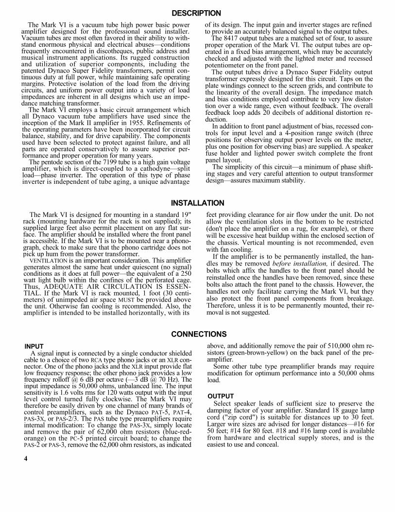
The Mark VI is designed for mounting in a standard 19" rack (mounting hardware for the rack is not supplied); its supplied large feet also permit placement on any flat sur-face. The amplifier should be installed where the front panel is accessible. If the Mark VI is to be mounted near a phono-graph, check to make sure that the phono cartridge does not pick up hum from the power transformer.
VENTILATION is an important consideration. This amplifier generates almost the same heat under quiescent (no signal) conditions as it does at full power—the equivalent of a 250 watt light bulb within the confines of the perforated cage. Thus, ADEQUATE AIR CIRCULATION IS ESSEN-TIAL. If the Mark VI is rack mounted, 1 foot (30 centi-meters) of unimpeded air space MUST be provided above the unit. Otherwise fan cooling is recommended. Also, the amplifier is intended to be installed horizontally, with its
feet providing clearance for air flow under the unit. Do not allow the ventilation slots in the bottom to be restricted (don't place the amplifier on a rug, for example), or there will be excessive heat buildup within the enclosed section of the chassis. Vertical mounting is not recommended, even with fan cooling.
If the amplifier is to be permanently installed, the han-dles may be removed before installation, if desired. The bolts which affix the handles to the front panel should be reinstalled once the handles have been removed, since these bolts also attach the front panel to the chassis. However, the handles not only facilitate carrying the Mark VI, but they also protect the front panel components from breakage. Therefore, unless it is to be permanently mounted, their re-moval is not suggested.
CONNECTIONS
INPUT A signal input is connected by a single conductor shielded
cable to a choice of two RCA type phono jacks or an XLR con-nector. One of the phono jacks and the XLR input provide flat low frequency response; the other phono jack provides a low frequency rolloff @ 6 dB per octave (—3 dB @ 70 Hz). The input impedance is 50,000 ohms, unbalanced line. The input sensitivity is 1.6 volts rms for 120 watts output with the input level control turned fully clockwise. The Mark VI may therefore be easily driven by one channel of many brands of control preamplifiers, such as the Dynaco PAT-5, PAT-4, PAS-3X, or PAS-2/3. The PAS tube type preamplifiers require internal modification: To change the PAS-3X, simply locate and remove the pair of 62,000 ohm resistors (blue-red-orange) on the PC-5 printed circuit board; to change the PAS-2 or PAS-3, remove the 62,000 ohm resistors, as indicated
4
above, and additionally remove the pair of 510,000 ohm re-sistors (green-brown-yellow) on the back panel of the pre-amplifier.
Some other tube type preamplifier brands may require modification for optimum performance into a 50,000 ohms load.
OUTPUT Select speaker leads of sufficient size to preserve the
damping factor of your amplifier. Standard 18 gauge lamp cord ("zip cord") is suitable for distances up to 30 feet. Larger wire sizes are advised for longer distances—#16 for 50 feet; #14 for 80 feet. #18 and #16 lamp cord is available from hardware and electrical supply stores, and is the easiest to use and conceal.
Be sure to maintain similar wiring "sense" for each speaker in a mono, stereo, or quadraphonic system, so that they will be connected in phase. Normally the "-", common, or ground terminal of each speaker is attached to the "c" terminal on the output barrier strip, or to the "sleeve" con-nection on the output jack. The other speaker terminal is attached to the correct impedance terminal (4, 8, 16) on the barrier strip (the "tip" connection on the output jack is nor-mally wired to the 8 ohm tap of the output transformer, although this connection may be changed to either the 4 ohm or the 16 ohm tap, if desired). Proper phase sense is easily maintained with lamp cord because one conductor is coded with a molded ridge on the outer insulation.
Two speakers are connected in phase when maximum low frequency output is heard when they are driven from a mono-phonic source. Lowered output is observed when the con-nection to one of the speakers is reversed (out of phase, or reversed polarity). When using multiple speakers on each channel, or with 4-channel systems, it is important that all of the speakers in the same area be wired in phase.
If stranded lamp cord is used, the wire ends should be "tinned" first with solder to avoid fraying. In any case, make certain that no wire strands can touch other than the in-tended terminal.
The "c" terminal of the amplifier is connected to the chassis, so the Mark VI may be used in multiples, if desired, with special output connections which require common grounds. If so, it will be necessary to connect together all the "c" terminals of the Mark VI amplifiers being used in the same system.
An in-phase signal at the input of the Mark VI amplifier provides an in-phase signal at the output. This is char-acteristic of all Dynaco tube and solid state amplifiers.
AC POWER The power cord should be plugged into a wall outlet pro-
viding 120 volts, 50/60 Hz (alternately 100 volts, 220 volts or 240 volts depending on the wiring of the primary of the power transformer). Do not attempt to switch the amplifier remotely by plugging it into a switched outlet on a control preamplifier unless the outlet is designated as a 5 amp, or higher capacity. The Dynaco PAT-5, which can handle 15 amps, may be used.
LOUDSPEAKER RATINGS Nominal speaker power ratings are a matter of concern.
There is currently no U.S. standard. Manufacturers usually provide a "music power" rating, or indicate amplifier power limits. These should not be confused with continuous, or "rms" power acceptance for a sustained period which will be substantially lower. It is rare for a speaker to be able to handle as much power near the frequency extremes as in the midrange. Single woofer high fidelity speaker systems rarely have "music" ratings as high as 100 watts, or continuous duty wide band sine wave ratings as high as 40 watts.
In view of the power limitations of most high accuracy speaker systems, the connection of two or four similar speakers in the same location to a single channel is often advisable, if high signal levels are wanted. Lacking more definitive advice, a rough test is to place your hand in front of the woofer when playing a loud passage at your antici-pated listening level. If you can feel any heat generated by
the voice coil, you should consider the need for additional speakers to reproduce that level safely. When high output, high accuracy reproduction is desired, a series-parallel con-nection of four 8 ohm speakers (such as the Dynaco A-35) on each channel provides a resultant 8 ohm load with excep-tional power handling capacity.
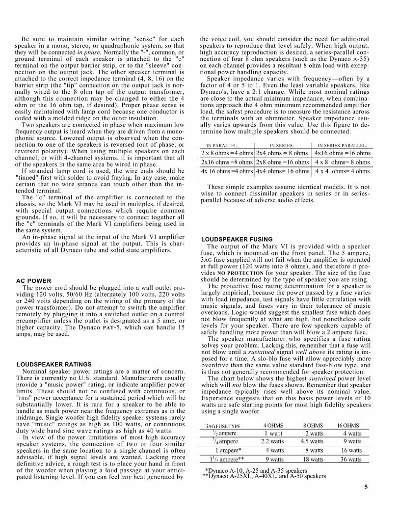
Speaker impedance varies with frequency—often by a factor of 4 or 5 to 1. Even the least variable speakers, like Dynaco's, have a 2:1 change. While most nominal ratings are close to the actual minimum impedance, when combina-tions approach the 4 ohm minimum recommended amplifier load, the safest procedure is to measure the resistance across the terminals with an ohmmeter. Speaker impedance usu-ally varies upwards from this value. Use this figure to de-termine how multiple speakers should be connected:
IN PARALLEL: IN SERIES: IN SERIES-PARALLEL: 2 x 8 ohms =4 ohms 2x4 ohms = 8 ohms 4x16 ohms =16 ohms2x16 ohms =8 ohms 2x8 ohms =16 ohms 4 x 8 ohms= 8 ohms4x 16 ohms =4 ohms 4x4 ohms= 16 ohms 4 x 4 ohms= 4 ohms
These simple examples assume identical models. It is not wise to connect dissimilar speakers in series or in series-parallel because of adverse audio effects.
LOUDSPEAKER FUSING The output of the Mark VI is provided with a speaker
fuse, which is mounted on the front panel. The 5 ampere, 3AG fuse supplied will not fail when the amplifier is operated at full power (120 watts into 8 ohms), and therefore it pro-vides NO PROTECTION for your speaker. The size of the fuse should be determined by the type of speaker you are using.
The protective fuse rating determination for a speaker is largely empirical, because the power passed by a fuse varies with load impedance, test signals have little correlation with music signals, and fuses vary in their tolerance of music overloads. Logic would suggest the smallest fuse which does not blow frequently at what are high, but nonetheless safe levels for your speaker. There are few speakers capable of safely handling more power than will blow a 2 ampere fuse.
The speaker manufacturer who specifies a fuse rating solves your problem. Lacking this, remember that a fuse will not blow until a sustained signal well above its rating is im-posed for a time. A slo-blo fuse will allow appreciably more overdrive than the same value standard fast-blow type, and is thus not generally recommended for speaker protection.
The chart below shows the highest sustained power level which will not blow the fuses shown. Remember that speaker impedance typically rises well above its nominal value. Experience suggests that on this basis power levels of 10 watts are safe starting points for most high fidelity speakers using a single woofer.
3AG FUSE TYPE 4 OHMS 8 OHMS 16 OHMS 1/2 ampere l watt 2 watts 4 watts3/4 ampere 2.2 watts 4.5 watts 9 watts 1 ampere* 4 watts 8 watts 16 watts
11/2 ampere** 9 watts 18 watts 36 watts
*Dynaco A-10, A-25 and A-35 speakers **Dynaco A-25XL, A-40XL, and A-50 speakers
5

ASSEMBLY INSTRUCTIONS
GENERAL ASSEMBLY INFORMATION Construction of the Mark VI is very simple when com-
pared to other kits. The printed circuit board for audio has been preassembled to save you some of the work, and the assembly that remains is in an open, uncluttered layout to make wiring quick and easy. The construction time will be several hours. It is better to work slowly and carefully rather than concern yourself about the time.
When you unpack the kit, check off the components against the parts list on page 23. Separate the hardware items in an egg carton or similar container. You can identify unfamiliar parts by checking them against the Pictorial Diagram, bearing in mind that the drawing is necessarily somewhat distorted for visual separation.
Have the proper tools at hand before starting construction. The tools necessary are:
1. A pencil-type soldering iron with a 3/16" tip or smaller of 40 to 60 watts rating, with a tip tempera- ture of 700 to 800° F.
2. A damp sponge or cloth to wipe the tip of the iron. 3. 60/40 rosin core solder not larger than 1/16" diam-
eter. 4. A medium sized screwdriver (1/4" blade). 5. Long nosed and diagonal cutting pliers. 6. Heavy "slip joint" pliers. 7. A single edged razor blade or inexpensive wire strip
ping tool for removing insulation. 8. Wood toothpicks. 9. Transparent or masking tape.
10. Heavy cardboard.
We do not recommend using a soldering gun. Not only can a gun provide more heat than is necessary—an unskilled user might damage printed circuit boards—but also many users tend to make poor solder connections, simply because they do not wait long enough for the gun to reach its operat-ing temperature each time. Use a conventional pencil type iron.
A good solder connection does not require a large amount of solder around the joint. A well-made connection looks smooth and shiny because the solder flows into the joint when both parts are hot enough.
There are four steps to making a good solder connection: 1. Make a good mechanical connection. 2. Heat both parts with the tip of the iron at the junction. 3. Apply solder to the junction until it melts and flows. 4. Allow the connection to cool undisturbed.
ALL SOLDERING MUST BE DONE WITH A GOOD GRADE OF ROSIN CORE SOLDER
Under no circumstances should acid core solder be used. Unmarked solder, cheap solder or any of doubtful origin should be discarded, and separate solder fluxes should never be used. The warranty is voided on any equipment in which 6
acid core solder or acid type fluxes have been used. Silver solder is not suitable. The recommended solder is 60/40 (60% tin, 40% lead) ROSIN CORE. Do not confuse this with 40/60, which is harder to use.
You should realize that many of the more delicate com-ponents are less likely to be damaged in the soldering pro-cess if you use a hot iron for a short time, rather than a cooler iron for a longer period. You will also make a better connec-tion with the hot iron. If you keep the iron clean by wiping the tip frequently, and occasionally add a small amount of solder to the tip, it will aid the transfer of heat to the con-nection. Do not allow too much solder to build up on the tip though, or it may fall onto adjacent circuitry.
One of the best ways to make a good mechanical connec-tion is to bend a small hook in the end of the wire, and then to crimp the hook onto the terminal lug. The amount of bare wire exposed need not be exactly 1/4 inch, but if it is too long, the excess might touch another terminal lug or the chassis. Do not wrap the wire around the lug more than one time, as this makes the connection difficult to remove if an error is made.
Many of the wiring steps will call for "preparing" a wire of a certain length and color. This involves cutting the neces-sary length of wire and stripping 1/4 inch of insulation from each end. This is most easily done with wire strippers, but diagonal cutters can be used if you are careful not to nick the wire and weaken it.
When soldering a lead to a numbered, plated-through hole on a circuit board, push the lead through the hole first. Do not push the wire all the way into the hole up to the insulation. Apply the solder and the hot iron at the same time to the junction of the hole and lead. The solder should melt very quickly; it should flow easily and fully into the hole and completely around the lead. Remove the iron and allow the connection to cool. It is essential to have a smooth, shiny flow of solder from the lead to the plated circuitry on the board.

WIRING THE KIT The position of all wire leads should follow the diagram
closely, bearing in mind that the pictorial diagram has neces-sarily been distorted somewhat to show all connections clearly. See that uninsulated wires do not touch each other unless, of course, they are connected to the same point. It is especially important that uninsulated wires or component leads or terminals do not touch the chassis accidentally.
Whenever one wire is to be soldered to a connection such as a lug terminal or hole, the instructions will indicate this by the symbol (S). If more than one wire is to be soldered to the same point, the instructions will cite the number of wires that should be connected to that point when it is to be soldered. If no soldering instruction is specifically given, do not solder; other connections will be made to that point before soldering is called for.
Check your work after each step, and make sure the entire step has been completed. When you are satisfied that it has been correctly done, check the space provided and go on to the next step. Be sure you read carefully the explanatory paragraphs in the assembly instructions.
Where stranded wire is used, as on the transformer leads, be very careful not to cut through the strands when stripping the end. Where stranded wire is supplied for hookup wire in the kit, the strands will be bonded together to minimize this likelihood and make handling easier.
All mounting screws are installed from the outside of the chassis, and a nut with lockwasher attached, called a KEP nut, is used except when otherwise specified.
This kit uses a variety of hardware. Before starting as-sembly, separate all the hardware by using an egg carton, muffin pan, or small cups. #4, #6, #10 and 1/4" machine screws with binder heads (flat tops with rounded sides) are used in various lengths. Much of the hardware used is #4 binder head in a 5/16" length. There are also #6 oval head screws with tapered sides, which are used only when attach-ing the XLR connector to the chassis.
TAKE THE TIME TO BE NEAT AND ACCURATE, and your amplifier will operate properly at first, and for many years.
MECHANICAL ASSEMBLY
1( ) Select the "U" shaped bottom plate with slanted sides, the four rubber feet, and four of the 1/4" diam-eter bolts (the largest hardware). Insert a bolt through each foot, and then mount a foot at each cor-ner of the bottom plate on the outside (sides turned away from you). No other hardware is required; the bottom plate is supplied with threaded nuts for these bolts. Set the assembly aside.
Select the black "L" shaped control bracket. Note that the bottom edge of the inside surface turns toward you. The three parts attached to this bracket will be mounted from the inside.
2( ) Select the 10,000 ohm control, part #145103, a 3/8"
nut, and a 3/8" thin lockwasher. Do not confuse this with the 100,000 ohm control, part #144104, which will be called for in the next step. Place a lockwasher on the threaded shaft, install the control in location BC with the lugs positioned as shown, and tighten the nut.
3( ) Select the 100,000 ohm control, part #144104, a 3/8" nut, and a 3/8" thin lockwasher. Place the lockwasher on the shaft, install the control in location LC, posi-tion the lugs as shown, and tighten the nut.
4( ) Select the meter switch, a 3/8" nut, and the last 3/8" lockwasher. Place the lockwasher on the shaft, install the switch in location MS, position the lugs as shown, and tighten the nut.
Set this assembly aside, and place the front panel in front of you. The front surface is printed. The parts attached to this panel will be mounted from the front. 5( ) Select the square fuse holder. Notice that one face is
marked "top". With this surface facing the top edge of the front panel, press the fuse holder into the right bottom square cutout. No hardware is used.
6( ) Select the power switch. Observe that the dark red jewel is positioned toward the bottom edge of the front panel. Press it into the left bottom rectangular cutout. No hardware is used.
7( ) Select the meter, the two small lamps, the two lamp sockets, the two pieces of insulating tubing, and six #4 KEP nuts (the smallest hardware). Install the meter upright from the outside. Carefully secure the meter with four KEP nuts. Avoid excessive force, since the meter is plastic. Snap each lamp into a lamp socket to where the socket engages the lamp de-tent, and then slip a piece of insulating tubing onto the lamp socket to cover the metal portion of the lamp and socket. Install a lamp socket on each of the lower meter mounting studs. Fasten each socket firmly with a second KEP nut.
Set this assembly aside, and select the chassis. The out-side back edge is printed. Some of the parts will be mounted from the outside, and others from the inside. 8( ) Select the 4-screw output barrier strip, and four each
5/8" #6 screws and #6 KEP nuts (next to the smallest hardware). This output strip mounts outside the chassis at the right back, so that its four lugs protrude through the slot. Insert the screws from the outside, and fasten with the KEP nuts on the inside. Make sure that the lugs do not touch any chassis metal.
9( ) Select the output jack, and the last 3/8" nut. Install the jack from the inside in the round hole adjacent to the output strip, and fasten with the nut on the out-side. Position the lugs and the flattened corner of the jack, as shown in the Pictorial Diagram. Avoid ex-cessive force on the plastic threads.
7
10( )Select the 3-pin XLR input socket, the two 3/8" #4 screws with oval heads, and two #4 KEP nuts. Install the XLR input from the outside in the round hole at the center back so that the pin location matches the Pictorial Diagram. Insert the screws from the outside. Do not use excessive force on the nuts.
Much of the hardware used to mount the parts in this kit is #4-40 x 5/16"—the smallest size. If no mention is made of the type of hardware, use this size. A set is one screw and one KEP nut. 11 ( ) Select the dual RCA input socket strip, the matching
insulator strip, and four #4 screws and KEP nuts. This input strip mounts inside next to the XLR in-put. Insert the screws from the outside, install the insulator first on the inside, followed by the input strip, and fasten with the KEP nuts.
12 ( ) Select the four 8-pin tube sockets, and eight sets of #4 hardware. Notice that each socket has a cutout or key way in its inside circular opening. The sockets mount from the inside in locations V2, V3, V4 and V5 so that each keyway points toward the right back of the chassis. Insert the screws from the outside.
13 ( ) Select the small 9-pin tube socket, and two sets of #4 hardware. Mount the socket from the outside in loca-tion TD-1. The blank pin location points toward the right back of the chassis. Insert the screws from the outside.
14 ( ) Select two of the 2-lug terminal strips, and two sets of #4 hardware. Install one of the strips in location T-l, and the other in location T-2, positioned as shown in the Pictorial Diagram. The screws are in-serted from the outside.
15 ( ) Select the three 6-lug terminal strips, the last 2-lug terminal strip, and 6 sets of #4 hardware. Install one each of the 6-lug strips in locations T-3, T-4 and T-5, and the 2-lug strip in location T-6, as shown in the Pictorial Diagram. One set of hardware is used to in-stall both T-6 and one end of T-3. Note T-4 and T-5 holes are the outermost pairs.
16 ( ) Select the three rubber grommets, and insert one each in the holes at locations G1, G2 and G3. They are simply squeezed and pressed in place.
17 ( ) Select the round fuse holder with attached hardware. Install it in the left back "D" shaped hole. The rub-ber washer stays outside the chassis.
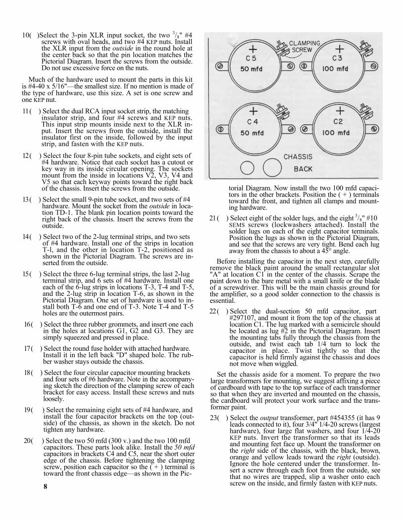
18 ( ) Select the four circular capacitor mounting brackets and four sets of #6 hardware. Note in the accompany-ing sketch the direction of the clamping screw of each bracket for easy access. Install these screws and nuts loosely.
19 ( ) Select the remaining eight sets of #4 hardware, and install the four capacitor brackets on the top (out-side) of the chassis, as shown in the sketch. Do not tighten any hardware.
20 ( ) Select the two 50 mfd (300 v.) and the two 100 mfd capacitors. These parts look alike. Install the 50 mfd capacitors in brackets C4 and C5, near the short outer edge of the chassis. Before tightening the clamping screw, position each capacitor so the ( + ) terminal is toward the front chassis edge—as shown in the Pic- 8
torial Diagram. Now install the two 100 mfd capaci-tors in the other brackets. Position the ( + ) terminals toward the front, and tighten all clamps and mount-ing hardware.
21 ( ) Select eight of the solder lugs, and the eight 3/8" #10 SEMS screws (lockwashers attached). Install the solder lugs on each of the eight capacitor terminals. Position the lugs as shown in the Pictorial Diagram, and see that the screws are very tight. Bend each lug away from the chassis to about a 45° angle.
Before installing the capacitor in the next step, carefully remove the black paint around the small rectangular slot "A" at location C1 in the center of the chassis. Scrape the paint down to the bare metal with a small knife or the blade of a screwdriver. This will be the main chassis ground for the amplifier, so a good solder connection to the chassis is essential. 22 ( ) Select the dual-section 50 mfd capacitor, part
#297107, and mount it from the top of the chassis at location C1. The lug marked with a semicircle should be located as lug #2 in the Pictorial Diagram. Insert the mounting tabs fully through the chassis from the outside, and twist each tab 1/4 turn to lock the capacitor in place. Twist tightly so that the capacitor is held firmly against the chassis and does not move when wiggled.
Set the chassis aside for a moment. To prepare the two large transformers for mounting, we suggest affixing a piece of cardboard with tape to the top surface of each transformer so that when they are inverted and mounted on the chassis, the cardboard will protect your work surface and the trans-former paint. 23( ) Select the output transformer, part #454355 (it has 9
leads connected to it), four 3/4" 1/4-20 screws (largest hardware), four large flat washers, and four 1/4-20 KEP nuts. Invert the transformer so that its leads and mounting feet face up. Mount the transformer on the right side of the chassis, with the black, brown, orange and yellow leads toward the right (outside). Ignore the hole centered under the transformer. In-sert a screw through each foot from the outside, see that no wires are trapped, slip a washer onto each screw on the inside, and firmly fasten with KEP nuts.

[If the alternate (Japanese) transformer, part #454354, has been supplied, invert the transformer on the right of your work surface with its attached mounting screw studs facing up. Mount the transformer on the right side of the chassis so that the holes in the chassis engage the transformer studs. Feed all 9 leads through the large center hole. Select four each large flat washers and 1/4-20 KEP nuts. Slide the transformer as far away from the right side of the chassis as possible, slip a washer onto each screw stud on the inside, and firmly secure the nuts.] 24( ) Select the power transformer, part #464023 (it has 14
leads connected to it), the choke, part #423355, and the remaining four 3/4" 1/4-20 screws and KEP nuts, and the last two flat washers. As before, invert the transformer on your work surface. Mount the trans-former on the left side, with the black, brown, orange, yellow, green-yellow, black-white and orange-white leads toward the back (inside) of the chassis. Ignore the center hole. Insert a screw through each foot from the outside, mount the choke on the inside over the two screws on the left, slip washers over the two screws on the right, see that no wires are trapped, and firmly secure the nuts.
[If the alternate (Japanese) transformer, part #464017, has been supplied, invert the transformer on the left with its mount-ing screw studs facing up. Mount the transformer on the left side so that the holes in the chassis engage the transformer studs. Feed all 14 leads through the large center hole. Mount the choke over the two studs on the left, slip washers over the screws on the right, slide the transformer as far away from the left side of the chassis as possible, and firmly secure with four KEP nuts.]
You may wish to work on the chassis with it placed ver-tically before you, resting on the sides of the transformers. Bend the transformer leads over the edge of the chassis to get them out of the way until their connection is called for.
WIRING THE OUTPUT STAGE 1( ) Prepare three 4" (10 cm) heavy yellow wires, three
5 1/2" (14 cm) yellow wires, one 4" (10 cm) black wire, and one 5 1/2" (14 cm) black wire. Remove 1/4" (.6 cm) of insulation from each end of the wires. Se-lect one of the shorter and one of the longer yellow wires, start with the wires even, and twist them uni-formly together to within 1/2"/ (1.3 cm) of the other end of the shorter wire (the longer wire should be about 1 1/2" [4 cm] longer than the short wire at this end). These twisted pairs, as well as the other twisted pairs in this kit, should be twisted uniformly 3 full turns every 2" (5 cm). In a similar manner twist to-gether the remaining two pairs of yellow wires, and the pair of black wires.
2( ) Select one of the yellow twisted pairs, and connect the 1 1/2" longer wire to tube socket V2 pin #2 (S). Connect the corresponding end of the other wire to V2 pin #7 (S). Connect the free end of one wire to V3 pin #2. Connect the remaining end to V3 pin #7.
3( ) Select another of the yellow twisted pairs, and con-nect the 1 1/2" longer wire to V3 pin #2 (S-2). Connect the corresponding end of the other wire to V3 pin #7 (S-2). Connect a wire at the free end to V4 pin #2. Connect the remaining end to V4 pin #7.
4( ) Select the remaining yellow pair, and connect the 1 1/2" longer wire to V4 pin #2 (S-2). Connect the corresponding end of the other wire to V4 pin #7 (S-2). Connect a wire at the free end to V5 pin #2. Connect the remaining end to V5 pin #7.
The leads connected to the power and output transformers have been precut to approximately their correct lengths. You may shorten them for neatness if you wish, but do not cut them too short for use, as this may void the warranty.
5( ) Select the heavy green lead and the heavy violet lead from the power transformer. Twist the leads uni-formly together for neatness, and connect the green lead to V5 pin #7. Connect the violet lead to V5 pin #2.
6( ) Select the black twisted pair, and connect the 1 1/2" longer wire to V5 pin #7 (S-3). Connect the cor-responding end of the other wire to V5 pin #2. We suggest crimping these wires around the pins if the pin holes are already filled with wires. Connect a wire at the free end to TD-1 pin #1. Connect the remain-ing end to TD-1 pin #6.
7( ) Prepare a 13 1/2" (34.5 cm) black wire. Connect one end to V5 pin #2 (S-4). Now twist this wire twice around the twisted pair from the previous step, and then feed the free end through the grommeted hole G3. The other end will be connected later.
Make certain that all of these twisted filament (heater) wires are positioned against the chassis. 8( ) Prepare a 4" (10 cm) black wire, but remove 1/2"
(1.3 cm) of insulation from each end, instead of the conventional 1/4" (.6 cm). Feed one end through V2 pin #8 and connect it to V2 pin #1. Solder both pins. Feed the other end through V3 pin #8, and connect it to V3 pin #1.
9( ) Prepare a 4" (10 cm) black wire, but remove 1/2" (1.3 cm) of insulation from each end. Feed one end through V4 pin #8, and connect it to V4 pin #1 (S). Feed the other end through V5 pin #8, and connect it to V5 pin #1. Solder V5 pin #1 only.
Each lug of the 2- and 6-lug terminal strips T-l, T-2, T-3, T-4 and T-5 has two holes, one at the tip, and the other at the base through the insulating material. For ease of con-nection, the steps involving these terminal strips will indi-cate soldering to the tip or to the base of a lug on them. The two holes will be soldered independently.
10( ) Prepare a 5 1/2" (14 cm) black wire, by removing the conventional 1/4" (.6 cm) of insulation from each end. Connect one end to V3 pin #1 (S-2). Connect the other end to T-4 lug #1 at the base (S).
11( ) Prepare a 3 1/2" (9 cm) black wire. Connect one end to V3 pin #8 (S-2). Connect the other end to V4 pin #8 (S-2).
12( ) Select one of the 1,000 ohm, 1/2 watt resistors (brown-black-red) , bend its leads 90° to its body, and cut its leads to 1/2" (1-3 cm) each. Connect one lead to V2 pin #5 (S). Connect the other lead to V2 pin #6.
13( ) Select another 1,000 ohm, 1/2 watt resistor (brown-black-red) , bend its leads 90° to its body, and cut its leads to 1/2" (1.3 cm) each. Connect one lead to V3 pin #5 (S). Connect the other lead to V3 pin #6.
14( ) Select another 1,000 ohm, 1/2 watt resistor (brown-black-red) , bend its leads 90° to its body, and cut its leads to 1/2" (1.3 cm) each. Connect one lead to V4 pin #5 (S). Connect the other lead to V4 pin #6.
9
15( ) Select the last 1,000 ohm, 1/2 watt resistor (brown-black-red) , bend its leads 90° to its body, and cut its leads to 1/2" (1.3 cm) each. Connect one lead to V5 pin #5 (S). Connect the other lead to V5 pin #6.
The leads in the next 2 steps are deliberately long. They will be arched toward the bottom plate for clearance. 16( ) Prepare a 3 3/4" (9.5 cm) black wire. Connect one
end to V2 pin #6 (S-2). Connect the other end to V3 pin #6.
17( ) Prepare a 3 3/4" (9.5 cm) black wire. Connect one end to V5 pin #6 (S-2). Connect the other end to V4 pin #6.
18 ( ) Select the blue-white and the green-white leads from the output transformer. Twist these leads neatly to-gether, and connect the green-white lead to T-l lug #1 at the base (S). Connect the blue-white lead to T-l lug #2 at the base (S). Make certain that these leads are not interchanged.
19 ( ) Select one of the 22 ohm, 2 watt resistors (red-red- black). Bend one lead 90° to its body, and cut that lead to 3/8" (1 cm). Do not bend the other lead, but cut it to 5/8" (1.8 cm). Connect the bent-lead end to V2 pin #4 (S). Connect the other lead to T-l lug #1 at the tip.
20( ) Select another 22 ohm, 2 watt resistor (red-red-black). Bend one lead 90° to its body, and cut it to 3/8" (1 cm). Connect the bent-lead end to V3 pin #4 (S). Connect the other lead to T-l lug #1 at the tip (S-2).
21( ) Select another 22 ohm, 2 watt resistor (red-red-black). Bend one lead 90° to its body, but do not cut it. Cut the other lead to 1" (2.5 cm). Connect the bent-lead end to V2 pin #3 (S). Connect the other end to T-l lug #2 at the tip. Trim off any excess lead at V2 pin #3.
22( ) Strip a 1 1/2" (4 cm) piece of insulation from the roll of yellow wire, and cut the insulation in two equal lengths. Set aside one length until it is called for.
23( ) Select another 22 ohm, 2 watt resistor (red-red-black). Bend one lead 90° to its body, do not cut it, but slip a length of insulation on it. Cut the other lead to 3/4" (2 cm). Connect the bent-lead end to V3 pin #3 (S). Connect the other end to T-l lug #2 at the tip (S-2). Trim off any excess lead at V3 pin #3.
24( ) Select the red, the green, and the blue leads from the output transformer. Twist these leads together, and connect the red lead to C3 lug #4. Although a total of four wires will eventually be soldered to this lug, we suggest connecting this lead close to the base of the lug (next to the terminal screw), and soldering it. Connect the green lead to T-2 lug #3 at the base (S). Connect the blue lead to T-2 lug #4 at the base (S).
25( ) Select another 22 ohm, 2 watt resistor (red-red-black). Bend one lead 90° to its body, and cut it to 3/8" (1 cm). Cut the other lead to 5/8" (1.8 cm). Connect the bent-lead end to V4 pin #4 (S). Connect the other lead to T-2 lug #3 at the tip.
26( ) Select another 22 ohm, 2 watt resistor (red-red-black). Bend one lead 90° to its body, and cut it to " (1 cm). Connect the bent-lead end to V5 pin #4 (S). Connect the other lead to T-2 lug #3 at the tip.
10
27( ) Select another 22 ohm, 2 watt resistor (red-red-black). Bend one lead 90° to its body, but do not cut it. Cut the other lead to 1" (2.5 cm). Connect the bent-lead end to V4 pin #3 (S). Connect the other end to T-2 lug #4 at the tip. Trim off any excess lead at V4 pin #3.
28( ) Select the last 22 ohm, 2 watt resistor (red-red-black). Bend one lead 90° to its body, do not cut it, but slip the remaining length of insulation on it. Cut the other lead to 3/4" (2 cm). Connect the bent-lead end to V5 pin #3 (S). Connect the other end to T-2 lug #4 at the tip (S-2). Trim off any excess lead at V4 pin #3.
29( ) Select the black lead from the output transformer, and connect it to C1 ground lug "B".
30( ) Select the brown lead from the output transformer, and connect it to output barrier strip lug #2 (S).
31( ) Prepare a 2 3/4" (7 cm) black wire. Connect one end to output strip lug #3. Connect the other end to out-put jack lug #1 (S).
32( ) Select the orange lead from the output transformer, and connect it to output strip lug #3 (S-2).
33( ) Select the 620 ohm, 2 watt resistor (blue-red-brown), bend its leads almost 90° to its body, and cut its leads to 3/4" (2 cm) each. Connect one lead to output strip lug #4. Connect the other lead to output strip lug #1.
34( )Prepare a 14 1/2" (37 cm) black wire. Connect one end to output terminal lug #4. Position this wire adjacent to the orange and brown leads from the output transformer, and connect the other end to T-4 lug #4 at the base (S).
35( ) Select the yellow lead from the output transformer, and connect it to output strip lug #4 (S-3).
36( ) Prepare a 3 1/2" (9 cm) black wire, but remove 3/4" (2 cm) of insulation from one end, and the usual 1/4" (.6 cm) from the other. Feed the long-stripped end through output jack lug #2 to lug #3, and solder both lugs. Connect the other end to output strip lug #1.
37( ) Prepare a 12 1/4" (31 cm) yellow wire. Connect one end to output strip lug #1 (S-3). Position this wire next to the brown, orange, and yellow wires from the output transformer on the right of the chassis, and feed it out the hole in the front of the chassis. The other end of this wire remains without connection at present.
38( ) Prepare a 9" (23 cm) yellow wire. Connect one end to C1 ground lug "C" (S). Quite a bit of heat is required to solder the outside ground lugs on this ca-pacitor. The other end of this wire is not connected at this time.
39( ) Select the four plastic ties. Group together the blue, the brown, the orange, and the yellow wires con-nected to the output strip and bind them together with two of the ties for a neat appearance, as shown in the Pictorial Diagram. Slip the male end of a tie under the group of wires, push the male end through the female end, pull it tight, and cut off any excess. In a similar manner tie together the other wires in the vicinity of the output transformer, as shown in the Pictorial Diagram.
WIRING THE POWER AND BIAS SUPPLIES
1( ) Strip the insulation from a 3" (7.5 cm) yellow wire. Connect one end of the bare wire to C2 lug #1. Con-nect the other end to C4 lug #5. "Tin" the entire length of this bare wire with solder and a hot iron so that the wire is solid and shiny.
2( ) Prepare a 1 1/2" (4 cm) yellow wire. Connect one end to C2 lug #2. Connect the other end to C3 lug #3.
3( ) Prepare another 1 1/2" (4 cm) yellow wire. Connect one end to C4 lug #6. Connect the other end to C5 lug #7.
4( ) Select the 7.8 ohm precision resistor, and cut its leads to 1" (2.5 cm) each. Connect one lead to V5 pin #8 (S-2). Connect the other lead to C2 lug #1.
5( ) Select one of the 220,000 ohm, 1/2 watt resistors (red-red-yellow), bend its leads 90° to its body, and cut its leads to 1/2" (1-3 cm) each. Connect one lead to C2 lug #1 (S-3). Connect the other lead to C2 lug #2 (S-2).
6( ) Select another of the 220,000 ohm, 1/2 watt resistors (red-red-yellow), bend its leads 90° to its body, and cut its leads to 1/2" (1.3 cm) each. Connect one lead to C4 lug #5 (S-2). Connect the other lead to C4 lug #6 (S-2).
7( ) Select another of the 220,000 ohm, 1/2 watt resistors (red-red-yellow), bend its leads 90° to its body, and cut its leads to 1/2" (1.3 cm) each. Connect one lead to C3 lug #3 (S-2). Connect the other lead to C3 lug #4.
8( ) Select the last 220,000 ohm, 1/2 watt resistor (red-red-yellow), bend its leads 90° to its body, and cut its leads to 1/2" (1.3 cm) each. Connect one lead to C5 lug #7 (S-2). Connect the other lead to C5 lug #8.
9( ) Prepare a 4" (10.5 cm) black wire, but remove 3/8" (1 cm) of insulation from one end, and the conventional 1/4" (.6 cm) from the other. Feed the long-stripped end through TD-1 pin #8, and connect it to TD-1 pin #7. Solder both pins. Connect the other end to C3 lug #4.
10( ) Select the longer lead of the two black leads from the choke, and connect it to C3 lug #4 (S-4).
11( ) Select the orange and the orange-white leads from the power transformer, and feed them under terminal strip T-3. Twist the leads neatly together, and con-nect them both to power fuse lug #1 (S-2).
NOTE: If this unit is being wired for 100 volts AC line (Japan), select instead the brown and the yellow leads, twist them to-gether, feed them under terminal strip T-3, and connect both leads to power fuse lug #1 (S-2).
If this unit is being wired for 220 or 240 volts AC line, select only the orange-white lead, feed it under terminal strip T-3, and connect it to power fuse lug #1 (S).
12 ( ) Select the red-yellow lead from the power trans- former, and also feed it under terminal strip T-3. Bend a hook at the free end, and connect it to the bare wire between C2 lug #1 and C4 lug #5 (S).
13 ( ) Prepare a 4" (10 cm) yellow wire, but remove 3/8" (1 cm) of insulation from one end, and the conven-tional 1/4" (.6 cm) from the other. Bend a hook at the long-stripped end, and connect it to the bare wire between C2 lug #1 and C4 lug #5 (S). Connect the other end to T-3 lug #1 at the base (S).
14 ( ) Select the green-yellow lead from the power trans- former, and connect it to T-3 lug #2 at the base (S).
15 ( ) Select the two red leads from the power transformer. Connect one (either) lead to T-3 lug #3 at the base (S). Connect the other lead to T-3 lug #4 at the base (S).
16 ( ) Select one of the .02 mfd disc capacitors, and cut its leads to 1/2" (1.3 cm) each. Connect one lead to T-3 lug #1 at the tip. Connect the other lead to T-3 lug #2 at the tip (S).
17( ) Prepare a 6 1/2" (16.5 cm) yellow wire. Connect one end to T-3 lug #1 at the tip (S-2). Connect the other end to C1 lug "A". Solder this wire and lug securely to the bare chassis.
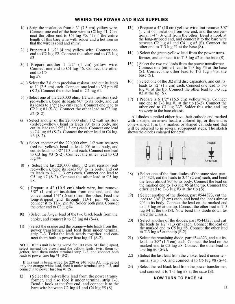
All diodes supplied either have their cathode end marked with a stripe, an arrow head, a colored tip, or this end is cone-shaped. It is this marked or shaped cathode end that will be referred to in several subsequent steps. The sketch shows the diodes enlarged for detail.
18 ( ) Select one of the four diodes of the same size, part #544323, cut the leads to 3/4" (2 cm) each, and bend the leads almost 90° to its body. Connect the lead on the marked end to T-3 lug #5 at the tip. Connect the other lead to T-3 lug #3 at the tip (S).
19 ( ) Select another of the diodes, part #544323, cut the leads to 3/4" (2 cm) each, and bend the leads almost 90° to its body. Connect the lead on the marked end to T-3 lug #6 at the tip. Connect the other lead to T-3 lug #4 at the tip (S). Now bend this diode down to-ward the chassis.
20 ( ) Select another of the diodes, part #544323, and cut the leads to 1/2" (1.3 cm) each. Connect the lead on the marked end to C5 lug #8. Connect the other lead to T-3 lug #5 at the tip (S-2).
21 ( ) Select the remaining diode, part #544323, and cut its leads to 5/8" (1.5 cm) each. Connect the lead on the marked end to C5 lug #8. Connect the other lead to T-3 lug #6 (S-2).
22 ( ) Select the last lead from the choke, feed it under ter- minal strip T-3, and connect it to C5 lug #8 (S-4).
23 ( ) Select the red-black lead from the power transformer, and connect it to T-5 lug #7 at the base (S).
NOW TURN TO PAGE 14
11
COMPONENT VALUES R 1 100,000 ohms, 1 w., 10% 115104 R 2 4,700 ohms, 1/2 w., 5% 113472 R 3 1,000,000 ohms, l w, 5% 116105 R 4 240,000 ohms, 1 w., 5% 116241 R 5 620 ohms, l w., 5% 116621 R 6 100 ohms, 1 w., 5% 116101 R 7 100,000 ohms, 1/2 w., 5% 113104 R 8 22,000 ohms, 1 w., 10% (matched within 1% to R9) 115223 R 9 22,000 ohms, 1 w., 10% (matched within 1% to R8) 115223 R 10 47,000 ohms, 1 w., 10% (matched within 1% to Rll and R12) 115473 R 11 47,000 ohms, 1 w., 10% (matched within 1% to R10 and R12) 115473 R 12 47,000 ohms, 1 w., 10% (matched within 1% to R10 and Rll) 115473 R101 240,000 ohms, 1 w., 5% 116241 R102 10,000 ohms, 1 w., 10% 115103 R103 18,000 ohms, 1 w., 10% 115183 R104 18,000 ohms, 1 w., 10% 115183 R105 220,000 ohms, 1/2 w., 10% 112224 R106 220,000 ohms, 1/2 w., 10% 112224 R107 220,000 ohms, 1/2 w., 10% 112224 R108 220,000 ohms, 1/2 w., 10% 112224 R109 22 ohms, 2 w., 10% 118220 R110 22 ohms, 2 w., 10% 118220 R111 22 ohms, 2 w., 10% 118220 R112 22 ohms, 2 w., 10% 118220 R113 1,000 ohms, 1/2 w., 5% 113102 R114 1,000 ohms, 1/2 w., 5% 113102 R115 7.8 (or 7.87) ohms, 3-5 w., 1% 120078 R116 1,000 ohms, 1/2 w., 5% 113102 R117 1,000 ohms, 1/2 w., 5% 113102 R118 22 ohms, 2 w., 10% 118220 R119 22 ohms, 2 w., 10% 118220 R120 22 ohms, 2 w., 10% 118220 R121 22 ohms, 2 w., 10% 118220 R122 620 ohms, 2 w., 10% 118621 R123 5,600 ohms, 1/2 w., 5% 113562 alternate (Japan) 7,500 ohms, 1/2 w., 5% 113752 R124 5,600 ohms, 1/2 w., 5% 113562 alternate (Japan) 7,500 ohms, 1/2 w., 5% 113752 R125 12,000 ohms, 1/2 w., 5% 113123 alternate (Japan) 15,000 ohms, 1/2 w., 5% 113153 R126 2,940 ohms, 1/2 w., 1% 130294 D101 Diode, 1 a., 200 prv 544012 D102 Diode, 3 a., 1,000 prv 544323 D103 Diode, 3 a., 1,000 prv 544323 D104 Diode, 3 a., 1,000 prv 544323 D105 Diode, 3 a., 1,000 prv 544323 D106 Diode, 1N541 Germanium 543541
C 1 .068 mfd, 500 v., 5%, mylar 267683 C 2 22 Pf, 500 v., 5%, mica 257220 C 3 68 Pf, 500 v., 5%, mica 257680 C 4 .5 (or .47) mfd, 500 v., 10%, mylar 267504 C 5 .5 (or .47) mfd, 500 v., 10%, mylar 267504 C 6 390 Pf, 500 v., 5%, mica 257391 C 7 150 Pf, 1000 v., 5%, mica 253151 C101 .05 (or .047) mfd, 200 v., 10% mylar 265473 C102a/b 50/50 mfd, 450 v., electrolytic 297107 C103 50 mfd, 75 v., electrolytic 284506 C104 50 mfd, 75 v., electrolytic 284506 C105 100 mfd, 300 v., electrolytic 285107 C106 100 mfd, 300 v., electrolytic 235107 C107 50 mfd, 300 v., electrolytic 285506 C108 50 mfd, 300 v., electrolytic 285506 C109 .02 mfd, 500 v., 20%, disc 227203 C110 .02 mfd, 500 v., 20%, disc 227203 V 1 Tube, 7199 517004 V102 Tube, 8417 (matched with V103, V104 and V105) 517008 V103 Tube, 8417 (matched with V102, V104 and V105) 517008 V104 Tube, 8417 (matched with V102, V103 and V105) 517008 V105 Tube, 8417 (matched with V102, V103 and V104) 517008 TD101 Tube, time delay, 6N030T 514003 P101 Potentiometer, 100,000 ohms, carbon, audio taper 144104 P102 Potentiometer, 10,000 ohms, carbon, linear taper 145103 CH101 Choke, .85 H., 400 ma., 13.5 ohms 423355 F101 Fuse, power, 5 a., AGC/3AG 342025 alternate 2.5 a., AGC/3AG (220-240 v. wiring) 342022 F102 Fuse, speaker, 5 a., AGC/3AG 342025 M101 Meter, 3 1/2" 508031 ML101 Meter Lamp, #337 526001 ML102 Meter Lamp, #337 525001 S101 Switch, power 331103 S102 Switch, meter 333169 T101 Transformer, power 464023 alternate (Japan) 464017 T102 Transformer, output 454355 alternate (Japan) 454354
13

24 ( ) Select the violet-white lead from the power trans- former, feed it under T-5, and through the grom-meted hole G3. Twist this wire and the black wire fed through this hole uniformly together on the top side of the chassis for future identification.
25 ( ) Select the remaining plastic tie. Group together the green and violet twisted pair, the violet-white, and the red-black leads from the power transformer, and bind them together with the tie for a neat appearance, as shown in the Pictorial Diagram. Cut off the excess tie.
26( ) Prepare a 6 1/4" (16 cm) black wire, and connect one end to T-4 lug #2 at the base (S). Feed it through hole Gl. The other end will be connected later.
27( ) Prepare a 4 1/2" (11.5 cm) yellow wire, and connect one end to T-4 lug #6 at the base (S). Feed it also through hole Gl. The other end will be connected later.
28( ) Select the 2940 ohm, 1/2 watt resistor (red-white-yellow-brown) , bend its leads 90° to its body, and cut its leads to 1/2" (1.3 cm) each. Connect one lead to T-4 lug #1 at the tip (S). Connect the other lead to T-4 lug #2 at the tip (S).
29( ) Select one of the 5600 ohm, 1/2 watt resistors (green-blue-red) , bend its leads almost 90° to its body, and cut its leads to 1/2". (1.3 cm) each. Connect one lead to T-4 lug #6 at the tip (S). Connect the other lead to T-4 lug #5 at the tip.
NOTE: If the alternate (Japanese) unit has been supplied, se-lect instead one of the 7500 ohm, 1/2 watt resistors (violet-green-red) , and install the part as indicated above. 30( ) Select the diode, part #543541, bend its leads 90° to
its body, and cut its leads to 1/2" (1.3 cm) each. Do not confuse it with the #544012 diode, which may look similar. Connect the lead on the marked end to T-4 lug #5 at the tip (S-2). Connect the other lead to T-4 lug #4 at the tip.
31( ) Select one of the 50 mfd, 75 volt electrolytic capaci- tors, bend its leads more than 90° to its body, and cut its leads to 3/4" (2 cm) each. Before connecting this part and a similar capacitor in another step, notice that they are marked for polarity with a ( + ) sign, a ( - ) sign, or sometimes both symbols. Con-nect the ( + ) lead to T-5 lug #12 at the base. Connect the other lead to T-5 lug #8 at the base (S).
NOTE: All components connected to this terminal strip should be on the left side.
32( ) Prepare a 5 1/2" (14 cm) black wire, and connect one end to T-5 lug #12 at the base (S-2). Connect the other end to Cl lug "D".
33( ) Select the remaining 50 mfd, 75 volt electrolytic ca- pacitor, and bend its leads more than 90° to its body. Cut the lead on the ( + ) end to 1" (2.5 cm), and cut the lead on the other end to 1 1/4" (3.3 cm). Strip 1" (2.5 cm) of insulation from the roll of yellow wire, and slip the insulation on the ( —) lead. Connect the ( + ) lead to T-5 lug #12 at the tip. Connect the other lead to T-5 lug #9 at the base.
34 ( ) Prepare a 6 1/2" (16.5 cm) yellow wire, and connect one end to T-5 lug #9 at the base (S-2). Feed it through hole G3. The other end will be connected later.
14
35( ) Prepare a 6 1/2" (16.5 cm) black wire, and connect one end to T-5 lug #10 at the base (S). Feed it also through hole G3. The other end will be connected later.
36( ) Prepare a 7" (18 cm) black wire, and connect one end to T-5 lug #11 at the base (S). Feed it through hole G3 and bend a hook at the other end for future identification. The other end will be connected later.
37( ) Select the diode, part #544012, bend its leads 90° to its body, and cut its leads to 1/2" (1.3 cm) each. Con-nect the lead on the marked end to T-5 lug #7 at the tip (S). Connect the other end to T-5 lug #8 at the tip.
38( ) Select one of the 18,000 ohm, 1 watt resistors (brown- gray-orange) , bend its leads 90° to its body, and cut its leads to 1/2" (1-3 cm) each. Connect one lead to T-5 lug #8 at the tip (S-2). Connect the other lead to T-5 lug #10 at the tip (S).
39( ) Select the 10,000 ohm, 1 watt resistor (brown-black- orange), bend its leads more than 90°, and cut its leads to 5/8" (1.5 cm) each. Connect one lead to T-5 lug #11 at the tip (S). Connect the other lead to T-5 lug #12 at the tip.
40( ) Prepare a 6 1/2" (16.5 cm) black wire, and connect one end to T-5 lug #12 at the tip (S-3). Feed it through hole G2. The other end will be connected later.
41 ( ) Select the 240,000 ohm, 1 watt resistor (red-yellow- yellow) , bend its leads 90° to its body, and cut its leads to 1/2" (1.3 cm) each. Connect one lead to Cl lug "B" (S-2). Connect the other lead to Cl lug #2.
42 ( ) Select the remaining 18,000 ohm, 1 watt resistor (brown-gray-orange), and cut its leads to 3/4" (2 cm) each. Strip 1/2" (1.3 cm) of insulation from the roll of yellow wire, and slip the insulation on one lead. Feed the insulated-lead end through TD-1 pin #3 to pin #4, and solder both pins. Connect the other lead to Cl lug #2.
The connecting pins for the XLR input have an open end rather than a hole. Simply insert the wire in the open end. When soldering is called for, hold it in place as you solder. 43 ( ) Strip the insulation from a 7/8" (2.3 cm) black wire.
Bend the bare wire in a 1/4" (1 cm) wide "U". Insert one end of the "U" into XLR input pin #1, and the other end into XLR pin #2. Solder pin #2 only.
44( ) Prepare a 3" (7.5 cm) black wire, and connect one end to XLR input pin #1 (S-2). Connect the other end to RCA input lug #1.
45( ) Prepare a 1 3/4" (4.5 cm) black wire, and connect one end to RCA input lug #1 (S-2). Connect the other end to RCA input lug #4.
46( ) Select the .05 mfd (or .047 mfd) capacitor, bend its leads 90° to its body, and cut its leads to 3/4" (2 cm) each. Connect one lead to RCA input lug #2 (S). Connect the other lead to RCA input lug #3.
47( ) Prepare another 1 3/4" (4.5 cm) black wire, and connect one end to XLR pin #3 (S). Connect the other end to RCA input lug #3.

WIRING PC-44 AND CONTROL BRACKET
The next two steps will call for the connection of the shielded audio cable. To prepare this cable for connection, first remove 3/4" (2 cm) of the outer plastic insulation. Use care doing this, so that you do not cut the fine strands of wire underneath. With the insulation removed, draw the fine "shield" wires to one side and twist them together. Then remove the conventional 1/4" (.6 cm) of insulation from the center wire, and also twist together these strands of wire. Finally, "tin" the shield and the center strands with your hot iron and a very small amount of solder to prevent fraying. 1( ) Prepare both ends of a 121/2" (31.5 cm) length of
shielded cable, as described in the above paragraph. Connect the shield wire at one end to RCA input lug #4 (S-2). Connect the corresponding center wire to RCA input lug #3 (S-3). Be certain that no strands of wire touch nearby hardware or other than the in-tended lug. Feed the cable over all the other wires to the front of the chassis, and then through hole G2. The other end will be connected later.
In future steps connections will be made to plated-through holes on the PC-44 circuit board. Insert the wire in the hole so that bare wire is visible on both sides of the board. Let the soldering iron contact the junction of wire and board circuitry as you feed solder to the junction. Solder should flow smoothly from the circuitry, around the hole to completely surround the wire. Keep the wire steady while the connection cools, and then wiggle it to make sure the connection is secure. If in doubt, reheat the connection and add more solder. 2( ) Select the PC-44 circuit board, and place it com-
ponents side down (foil pathway side toward you). Connection will be easier if all 12 of the numbered, solder-filled holes are cleaned out. Use a wood tooth-pick and a hot iron.
3( ) Prepare both ends of a 4 1/2" (11 cm) length of shielded cable, as described. Connect the center wire at one end to PC-44 hole #4 from the components side and solder the wire on the other (foil pathway) side. [Hole #4 is partially hidden by a resistor.] Connect the corresponding shield wire to PC-44 hole #3 from the components side, and solder the wire on the foil side. Feed the cable through hole G2 in the chassis from the inside. The other end will be con-nected later.
4( ) select the "L" shaped control bracket assembly, the four 1 1/8" #6 screws and KEP nuts, and the four 3/4" spacers. Insert two of the screws first through the bracket assembly from inside the bend, and mount the bracket over the two front holes from outside the chassis between the transformers so that the control shafts face front. Insert spacers inside the chassis, then install the properly oriented circuit board, and loosely affix with KEP nuts. Insert the other two screws through the chassis, install spacers inside, followed by the circuit board, and the KEP nuts. Now tighten all the hardware.
You will now connect the free ends of many of the wires fed through chassis holes G1, G2, and G3 to the controls BC and LC, and the switch MS on the bracket assembly. For access, place the chassis so the front edge is flat on the work surface, and the transformers point toward you. Refer to the accompanying sketch for connection of these parts.
5( ) Select the straight black wire from chassis hole G3 and connect it to BC lug #3 (S). (Ignore the black wire which has been twisted with the violet-white wire.)
6( ) Select the yellow wire from hole G3, and connect it to BC lug #2 (S).
7( ) Select the black wire with a hook bent in it from chassis hole G3 and connect it to BC lug #1 (S).
8( ) Select the shielded cable which has been connected to the RCA input socket and is fed through hole G2. Do not confuse this with the shielded cable con-nected to PC-44, which will be called for in the next step. Connect the center wire to LC lug #5 (S). Connect the shield wire to LC lug #6.
9( ) Select the shielded cable which has been connected to PC-44 and is also fed through hole G2. Connect the center wire to LC lug #4 (S). Connect the shield wire to LC lug #6 (S-2).
10 ( ) Select the yellow wire from hole G1, and connect it to MS lug #4.
11 ( ) Select the remaining 5600 ohm, 1/2 watt resistor (green-blue-red), bend its leads 90° to its body, and cut its leads to 1/2" (1.3 cm) each. Connect one lead to MS lug #4 (S-2). Connect the other lead to MS lug #3. Position this resistor across the back of MS, but do not permit a resistor lead to touch any metal portion of the switch.
NOTE: If the alternate (Japanese) unit has been supplied, se-lect instead the remaining 7500 ohm, 1/2 watt resistor (violet-green-red), and install the part as indicated above. 12 ( ) Select the 12,000 ohm, 1/2 watt resistor (brown-red-
orange), bend its leads 90° to its body, and cut its leads to 1/2" (1.3 cm) each. Connect one lead to MS lug #3 (S-2). Connect the other lead to MS lug #2 (S). Also position this resistor across the back of MS.
NOTE: If the alternate (Japanese) unit has been supplied, select instead the 15,000 ohm, 1/2 watt resistor (brown-green-orange), and install the part as indicated above.
15

13( ) Prepare a 3 1/2" (9 cm) yellow wire, and connect one end to MS lug #5 (S). The other end will be con-nected later.
14( ) Select the black wire from hole G1, and connect it to MS lug #1 (S).
Turn the amplifier over, positioned as shown in the Pic-torial Diagram. You will now connect wires to the remain-ing numbered holes on PC-44. Each wire is connected and soldered from the foil pathway side of the board—the side toward you. 15( ) Prepare a 3 3/4" (9.5 cm) black wire, and connect
one end to hole #6 (S). Position this wire to the left along the back edge of PC-44, and connect the other end to T-5 lug #9 at the tip (S).
16( ) Prepare a 41/2// (11 cm) black wire, and connect
one end to hole #2 (S). Position this wire along the left edge, around the board, and connect the other end to C1 lug"D" (S-2).
17( ) Prepare a 3 1/2" (9 cm) black wire, and connect one end to hole #12 (S). Connect the other end to C1 lug #1 (S). Position this wire around the right edge of the board.
18( ) Prepare a 2 3/4" (7 cm) black wire, and connect one end to hole #11 (S). Connect the other end to C1 lug #2 (S-3). Position this wire at least 1/2" (1.3 cm) to the left of hole #10.
19( ) Prepare a 2 1/4" (6 cm) black wire, and connect one end to hole #9 (S). Connect the other end to T-4 lug #4 at the tip (S-2).
20( ) Prepare a 7 1/4" (18.5 cm) black wire, and connect one end to hole #5 (S). Position this wire along the left edge of the board, and connect the other end to T-2 lug #3 at the tip (S-3).
21( ) Prepare two 4 1/2" (11.5 cm) black wires. Start with the wires even, and twist them uniformly together to within V2" (1.3 cm) of the other ends of the wires. Connect one end of one wire to hole #8 (S), and the corresponding end of the other wire to hole #7 (S). Connect either wire at the free end to TD-1 pin #1 (S-2). Connect the remaining end to TD-1 pin #6 (S-2). These twisted wires should be arched in the air, away from PC-44, until they connect at their respective ends.
22( ) Prepare a 5 1/4" (13.5 cm) black wire, and connect one end to hole #10 (S). Connect the other end to V3 pin #6 (S-3). This wire, as well as the black wire connected between V3 pin #6 and V2 pin #6, should be arched in the air, away from other com-ponents and wires, until they connect at their respective ends.
23( ) Prepare another 5 1/4" (13.5 cm) black wire, and connect one end to hole #1 (S). Connect the other end to V4 pin #6 (S-3). This wire, as well as the black wire connected between V4 pin #6 and V5 pin #6, should be arched in the air, away from other components and wires. Note, however, that the shielded cable connected to the input sockets may come in contact with the black wire connected be-tween V4 pin #6 and V5 pin #6.
16
24( ) Select the line cord and the strain relief. Mark the cord 112 1/2" (32 cm) from the stripped wire ends. Bend the cord sharply back on itself at the mark-ing so that a "V" is formed. See the accompanying sketch. Install the strain relief through the remain-ing hole in the left back corner of the chassis. The small end of the strain relief faces the stripped end of the wire. With heavy pliers, crimp the two halves of the strain relief together around the wire to par-tially shape the wire before insertion. Now grasp the larger diameter portion of the strain relief with the tips of the pliers, squeeze it fully closed, and insert the combination from the outside. The strain relief snaps into its locked position when fully inserted.
25( ) Separate the two conductors of the line cord from the stripped end to the strain relief, and cut off 9 1/2" (24 cm) from one (either) conductor. Strip about 3/8" (1 cm) of insulation from the short-cut con-ductor, and connect it to power fuse holder lug #2 (S). Position the other (long) conductor against the chassis on the left side. This conductor will be connected later.
FINAL ASSEMBLY Before attaching the front panel assembly in the next
step, you should check carefully for any insecure connec-tions, and for any possibility of bare wires contacting other than the intended terminal.
Leave the amplifier upside down, as shown in the Pic-torial Diagram, but position it so that the front edges of both transformers are slightly over the edge of your work surface. 1( ) Select the front panel assembly, and two 1/2" #10
black screws with large (truss) heads. Support the panel in front of the amplifier near its final loca-tion (the panel will be upside down). See that the speaker fuse and the power switch on the front panel pass through their respective openings in the chassis. Now attach the panel loosely on the front of the chassis with the screws inserted from the front. No other hardware is required, since the chassis is sup-plied with threaded nuts.
You will now connect the free ends of the wires from underside the chassis to parts on the front panel. 2( ) Select the yellow wire from C1 lug "C", and connect
the free end to speaker fuse holder lug #2 (S). 3( ) Select the yellow wire from output strip #1, and con-
nect the free end to speaker fuse holder lug #1 (S).
4( ) Select the brown and the yellow leads from the power transformer, twist them neatly together, and connect both leads to power switch lug #3 (S-2).
NOTE: If this unit is being wired for 100 volts AC line, select instead the orange and the orange-white leads, twist them to-gether, and connect both leads to power switch lug #3 (S-2).
If this unit is being wired for 220 volts AC line, select instead only the orange lead, and connect it to power switch lug #3 (S).
If this unit is being wired for 240 volts AC line, select instead the orange and the black-white leads, twist them together, and connect both leads to power switch lug #3 (S-2).
5( ) Select the remaining conductor of the line cord, and connect it to power switch lug #2.
6( ) Select the last .02 mfd disc capacitor, and cut its leads to 1/2" (1.3 cm) each. Connect one lead to power switch lug #2 (S-2). Connect the other lead to power switch lug #1.
7( ) Select the black and the black-white leads from the power transformer, twist them together, and connect both leads to power switch lug #1 (S-3).
NOTE: If this unit is being wired for 100 volts AC line, com-plete step 7, as indicated above.
If this unit is being wired for 220 volts AC line, select only the black transformer lead, and connect it to power switch lug #1 (S-2). In addition, select the yellow transformer lead, and con-nect it to terminal strip T-6 lug #13 at the tip (S). Also, select the brown and the black-white transformer leads, twist them to-gether, and connect both leads to T-6 lug #14 at the tip (S-2).
If this unit is being wired for 240 volts AC line, select only the black transformer lead, and connect it to power switch lug #1 (S-2). In addition, select the yellow transformer lead, and con-nect it to terminal strip T-6 lug #13 at the tip (S). Also, select the brown transformer lead, and connect it to T-6 lug #14 at the tip (S).
This completes the soldering of the underside of the Mark VI. Notice that terminal strip T-6 is without con-nection, unless the unit has been wired for 220 or 240 volts AC line. Particularly check your soldering on the power switch to see that when the front panel is in its final posi-tion, no strands of wire can touch the edge of the choke, or another connection. Now turn the amplifier over and shake out any bits of solder or pieces of wire or insulation. 8( ) Very carefully remove the two 1/2" #10 black screws
which have loosely attached the front panel assem-bly to the chassis, and allow the speaker fuse and the power switch to support the panel. Now select the bottom plate with slanted sides, invert it over the chassis, and slide it in place so that its front flanges fit between the chassis and the front panel.
9( ) Select the two metal handles and the four 1/2" #10 black screws with large heads. Attach the handles to the front of the panel with the screws inserted from the front. The screws engage threaded nuts in the chassis and the front flanges of the bottom plate. Firmly secure the screws.
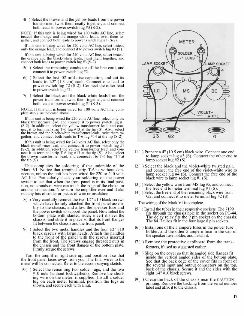
Turn the amplifier right side up, and position it so that the front panel faces away from you. The final wires to the meter will be connected. Refer to the accompanying sketch. 10( ) Select the remaining two solder lugs, and the two
#10 nuts (without lockwashers). Remove the short-ing wire on the meter, if supplied. Install a solder lug on each meter terminal, position the lugs as shown, and secure each with a nut.
11 ( ) Prepare a 4" (10.5 cm) black wire. Connect one end to lamp socket lug #3 (S). Connect the other end to lamp socket lug #2 (S).
12 ( ) Select the black and the violet-white twisted pair, and connect the free end of the violet-white wire to lamp socket lug #4 (S). Connect the free end of the black wire to lamp socket lug #1 (S).
13 ( ) Select the yellow wire from MS lug #5, and connect the free end to meter terminal lug #1 (S).
14 ( ) Select the free end of the remaining black wire from G2, and connect it to meter terminal lug #2 (S).
The wiring of the Mark VI is complete. 15 ( ) Install the tubes in their respective sockets. The 7199
fits through the chassis hole in the socket on PC-44. The delay relay fits the 9 pin socket on the chassis. The 8417 tubes fit in the four large 8 pin sockets.
16 ( ) Install one of the 5 ampere fuses in the power fuse holder, and the other 5 ampere fuse in the cap of the speaker fuse holder, and install it.
17 ( ) Remove the protective cardboard from the trans- formers, if used as suggested earlier.
18 ( ) Slide on the cover so that its angled side flanges fit inside the vertical angled sides of the bottom plate. See that the back edge of the cover fits in front of the several input and output connectors on the top, back of the chassis. Secure it and the sides with the eight 1/4" #10 black screws.
19 ( ) Clean the back of the chassis near the CAUTION printing. Remove the backing from the serial number label and affix it to the chassis.
17

INITIAL ADJUSTMENT—BIASET
Plug the line cord into a conventional 120 volts AC line (alternately 100 volts, 220 volts or 240 volts), and turn the power switch on. It is safe to operate the Mark VI without connection to the input or the output. The red lamp in the power switch and the lights in the meter should glow. While the tubes are becoming warm, on the front panel turn the meter range switch to the "Adjust for 0" position, and turn the Biaset potentiometer to approximately its center of rota-tion. A bladed screwdriver adjusts these recessed controls. Although the meter will begin showing a bias reading quickly, it will take at least 30 seconds before the output tubes draw their correct current. After almost a minute, adjust the Biaset potentiometer to read "0" on the meter. Allow the amplifier to operate this way for three or four more minutes, and readjust the Biaset control to read "0" once again, if necessary. There may be some drifting of the read-ing as the output tubes are initially used, but this will sta-bilize within an hour, after which no further adjustment is required at this time. It should be understood, however, that this voltage is in direct proportion to line variations and therefore it is normal for there to be small changes. These will have no effect on performance.
After initially setting the bias, turn the meter range switch to the next (—3 dB) position.
Although the adjustment of Biaset is semi-permanent, it is good practice to check this voltage three or four times during the useful life of the output tubes (1,000-1,500 hours). If the amplifier is used continuously, Biaset should be checked at least weekly. If the amplifier is in a mobile instal-lation, we recommend checking the Biaset every time the amplifier is set up in a new location. Of course, it must be checked and reset at times of output tube replacement or other types of repair or maintenance work.
The Biaset adjustment must be made when no signal is going through the amplifier, for it is normal for this voltage measurement to vary considerably with signal going through the amplifier.
If it is not possible to set bias—the control range of the potentiometer is insufficient to obtain the correct "0" read-ing—do not operate the amplifier until the cause of the dif-ficulty has been established. Operation with incorrect Biaset can lead to damage to the output tubes and/or to other components.
OUTPUT METER READING
The action of the meter supplied is "fast" enough to re-spond to substantial musical peaks, but no meter can accurately indicate the magnitude of transient waveforms which occur in music. However, with an accurate 4, 8 or 16 ohm load, the meter is a measure of output power. A square wave test signal puts out approximately 11% more voltage than the equivalent sine wave meter indication.
To protect the meter from "pegging" (overdrive), it is recommended that the —3 dB position of the recessed meter range switch be used where the anticipated power levels are not known, and when starting any test. Switching to suc-cessively higher ranges (—9 dB or —15 dB) until the loudest
passages indicate near "0" will yield the most information. The accompanying chart lists 4 ohm, 8 ohm and 16 ohm load power outputs in watts for each meter range.
SCALE -3dB METER RANGE-9dB
-15 dB
+ 3 120 30 7.6 0 60 15 3.8
- 3 30 7.5 1.9 -10 6 1.5 0.38
18

IN CASE OF DIFFICULTY The design of the Mark VI is inherently trouble free.
However, a mistake in assembly or a defective component can affect its performance or make it inoperative. The wiring should be checked step-by-step to make certain that all the connections have been made in accordance with these in-structions. Since many times the builder will tend to make the same error in checking his work as when building the amplifier, the best procedure is to have someone familiar with the product check out your work against the instructions.
The tubes should begin to glow after a few seconds of warmup (note, however, no signal will pass through the amplifier for 30 seconds, because of the time delay relay for the 7199 tube). If the tubes do not glow, there is probably no AC voltage getting into the amplifier, which may indicate a blown fuse. FUSE FAILURE
If the power fuse fails without apparent cause, always replace it with a 5 ampere AGC/3AG type, if the amplifier is wired for 120 volts or 100 volts line; use a 2.5 ampere AGC/3AG fuse if the Mark VI is wired for 220 volts or 240 volts line. Never use other than these sizes.
If the power fuse fails within about 30 seconds of turning the amplifier on, disconnect (unsolder) the two red B+ leads from the power transformer (terminal strip T-3 lug #3 and lug #4), tape the lead ends to protect them, and install another fuse. If the fuse holds, the four B+ rectifier diodes, part #544323, should be checked. A properly operating diode has a very high resistance when the probes of a meter are connected in one direction, and a much lower resistance when the probes of the meter are reversed. If one or more diode is either open or shorted, replacement of all four is suggested.
If the power fuse fails at turn on with the red transformer leads disconnected, there is either gross miswiring or a de-fective power transformer.
If the B+ diodes are not at fault, the 50 mfd, the 100 mfd or a section of the dual-section 50 mfd capacitors may be shorted or miswired. Generally shorts in this section will show up by measuring the resistance from the "+" capacitor terminal to ground (chassis). The amplifier must be un-plugged from the AC line. The resistance should exceed 100,000 ohms. TUBE FAILURE
If one or all of the 8417 output tubes glows a bright red in its plate section after warmup, it is possible that a tube is defective. There also may be a fault in the bias supply which supplies negative voltage to the output tubes, measurable at pin #5 of each 8417 (use a TVM or VTVM). The actual value of the negative voltage will depend on the setting of the bias potentiometer, but with the Biaset reading set to "0", the negative voltage at the output tubes should be within 20% of minus (—) 26 volts. If the four tubes have different negative voltages at pin #5, there is a defective component or miswiring. A small difference indicates either a runaway output tube or a leaking (defective) 0.5 mfd (0.47 mfd) coupling capacitor on the PC-44 printed circuit board. If one tube has no negative voltage, there almost has to be an open connection from the bias supply to this tube.
If there is a single glowing tube and no TVM or VTVM is available, it is easy to find the fault by interchanging tubes.
If any tube in the same socket exhibits the glow, the fault is in the circuitry associated with that socket. If the same tube glows in any socket, it is more than likely a bad tube (in this case, all tubes are suspect).
When it is necessary to change the 8417 output tubes, use only a matched set of four. Even though only one or two in a set may be bad, we recommend that all four be replaced at the same time. Matched sets may be obtained directly from Dynaco.
There are no substitute tube types for the 8417, 7199, or 6N030T used in this amplifier. NO SIGNAL
If there is no signal coming through the amplifier, remove the input cable to see whether insertion of the plug makes a "thump" through the loudspeaker. If so, then there is a defective audio cable, preamplifier or other associated equip-ment, but not in the amplifier. However, if there is no "thump" when inserting the plug, then the amplifier or the speaker fuse is at fault. Try a new fuse first.
A defective 6N030T delay relay tube will also prevent signal from passing through the amplifier, because it controls B+ voltage to the 7199 driver-inverter. Therefore, if the power supply is putting out B+, and the output tube voltages are normal, yet the 7199 has no B+ voltage, check the delay relay for proper operation.
If a meter is available, voltage measurements should be taken and compared with the voltage chart included in these instructions. With an incoming line voltage of 120 volts AC, departures of more than ± 10% from the values shown indi-cate probable malfunctioning of some of the circuit components. HUM AND NOISE
If excessive hum or noise appear, it is necessary to deter-mine whether they occur within the amplifier, for sometimes noise in a preamplifier will be blamed on the amplifier. The simple test is to turn down the front panel level control at the input of the amplifier to see if the same noise is present. If the noise is gone with the level control fully counterclock-wise, it is in the preceding equipment which should then be checked. If the noise remains, it is probably in the amplifier.
With the amplifier off, remove the 7199 and then turn the amplifier on. With this tube removed, the feedback network is cut so that the noise should be higher than with the tube in place. If the noise remains the same or drops with this tube out, the problem lies in the tube or circuitry surround-ing this tube on the printed circuit board. First try a replace-ment 7199.
If under the above test the noise does increase, more than likely the 7199 and its associated circuitry are all right. The problem then lies either in the circuitry of the output stage, which would include the output tubes themselves, or in the power or bias supplies. Excessive hum, for instance, can be caused by the failure of a B+ or bias diode, or by a defective B+ or bias capacitor.
Sizzling sounds through the loudspeaker may come from poor contacts between circuit elements and ground connec-tions. Make certain that the single chassis ground connec-tion in the Mark VI is securely soldered (capacitor C-l lug "A", as indicated in the pictorial diagram).
19

VOLTAGES AND PC-44 BOARD LAYOUT
The charts list the voltages and the location of the test points. The values are based on a 120 volts, 60 Hz line, shorted input, and no load connected to the output. All vol-tages are with respect to circuit ground, except for AC heater voltages—which should be measured from tube pin to pin. Tolerance: ± 10%.
VOLTAGE PICTORIAL CIRCUIT LOCATION 395 v. AC T-3 Terminal Strip lug #3, #4 60 v. AC T-5 Terminal Strip lug #7
+510 v. DC C5 Capacitor lug #8 +505 v. DC C3 Capacitor lug #4 - 80 v. DC T-5 Terminal Strip lug #8
Tube Pin # 8417 (Any) 7199 6N030T
1 1.87 290* 2 80* — 3 500 30* 505 4 6.3 AC 502 6.3 AC 6.3 AC 505 5 6.3 AC -26** 6.3 AC 6.3 AC 505 6 -26** .7 7 0 - 8 1.87 90* 505 9 80* 505
* Minor variations in current drain of the 7199 tube will cause large changes in electrode voltages without detrimen- tal effect on performance. Therefore, these voltage measure ments are only approximate and may vary widely.
* * These bias voltages must be measured with a TVM or VTVM. These measurements must be identical on all four 8417 tubes.
20
NOTE: When measuring voltages, it is important to take volt meter accuracy into account. Most volt meters are spe-cified for accuracy with respect to the range selected. This means, for example, that a voltage reading on a ± 5% meter could be off by ± 50 volts on the 1,000 volt range. In the Mark VI, this could imply an incorrect indication when measuring the high voltage B+, for example, which has been specified ± 51 volts (with a 120 volts line). Even if the vol-tage were exactly 510 volts, a ± 5% meter reading could indicate a voltage from 398 to 602 and still be within the specifications of both the meter tolerance and the voltage tolerance. It is therefore necessary to always consider the tolerance of both the voltage being measured and of the measuring instrument.
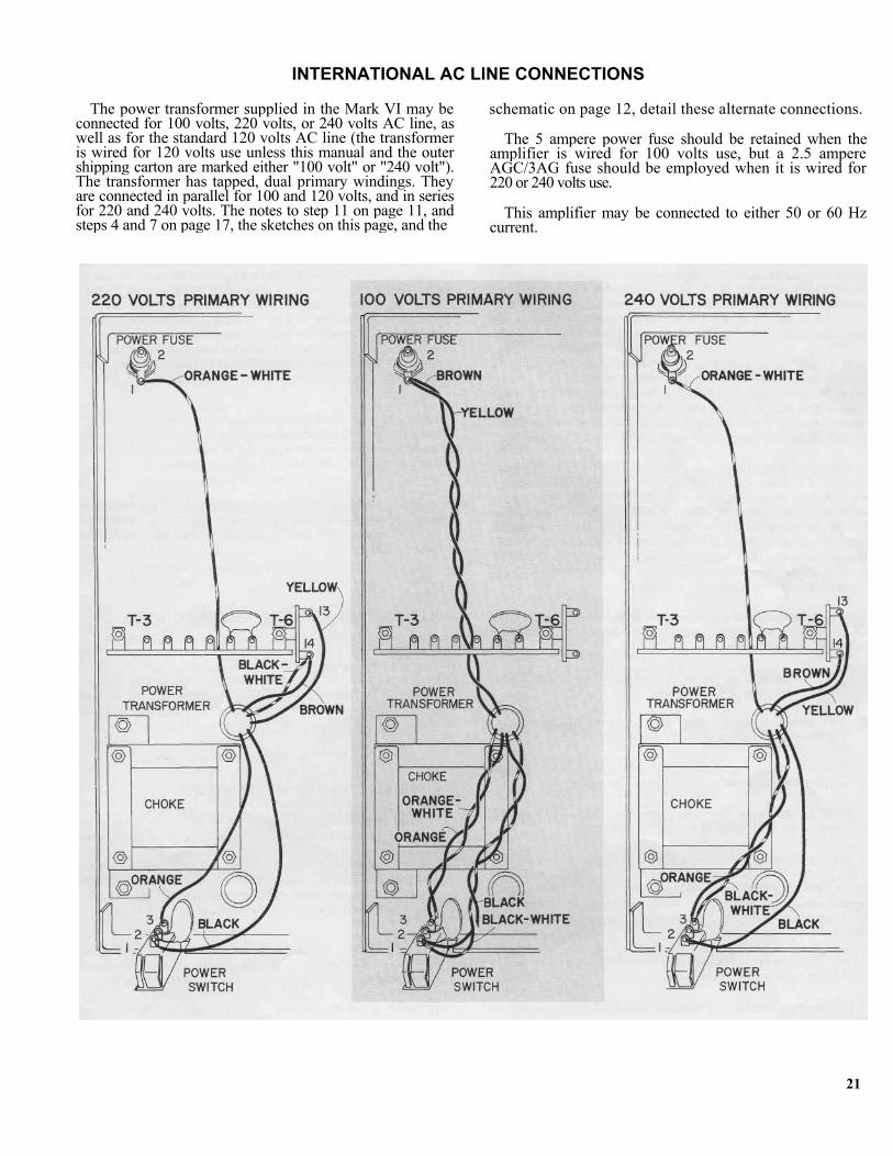
INTERNATIONAL AC LINE CONNECTIONS
The power transformer supplied in the Mark VI may be connected for 100 volts, 220 volts, or 240 volts AC line, as well as for the standard 120 volts AC line (the transformer is wired for 120 volts use unless this manual and the outer shipping carton are marked either "100 volt" or "240 volt"). The transformer has tapped, dual primary windings. They are connected in parallel for 100 and 120 volts, and in series for 220 and 240 volts. The notes to step 11 on page 11, and steps 4 and 7 on page 17, the sketches on this page, and the
schematic on page 12, detail these alternate connections.
The 5 ampere power fuse should be retained when the amplifier is wired for 100 volts use, but a 2.5 ampere AGC/3AG fuse should be employed when it is wired for 220 or 240 volts use.
This amplifier may be connected to either 50 or 60 Hz current.
21
SERVICE POLICY AND LIMITED WARRANTY
The Mark VI has been carefully engineered to provide many years of musical enjoyment without difficulty. Each factory-assembled Mark VI has been subjected to a full complement of performance tests prior to shipment. Never-theless, through damage in transit, faulty kit assembly, or human error, service may sometimes be required.
To provide rapid and reliable service, Dynaco has autho-rized competent, well-equipped service facilities in several localities in the United States and Canada, in addition to its service facility at the factory. These stations are autho-rized to make repairs in and out of warranty under the terms listed below. Service is always available at the factory, but you will often find a more convenient facility locally. A cur-rent list of these facilities is enclosed. Write to Dynaco for the name of the service station nearest you.
It is the owner's responsibility to take or send the unit freight prepaid to the service facility. A dated bill of sale must be submitted. In the event that you incorrectly diagnose which unit is faulty, please understand that you will be responsible for a check-out charge on any properly perform-ing kit or factory-assembled unit submitted for testing.
Shipment should be made via motor freight, REA Express (CN or CP Express in Canada), or Bus Package Express. DO NOT USE PARCEL POST FOR IT IS NOT A SAFE METHOD OF SHIPPING ELECTRONIC EQUIPMENT. Should damage occur due to unauthorized parcel post shipment of the complete ampli-fier, repairs will be made at the owner's expense, as neither the factory nor the service stations has the facilities to process parcel post claims. Be sure the shipment is fully insured (note Bus Express limitations).
When shipping the amplifier, use the original carton with all the styrofoam inserts. Include with the returned unit the following information:
1. Your name and complete shipping address (Post Office box numbers are not suitable);
2. The serial number (from the cover of this manual), together with a copy of your dated bill of sale;
3. The symptoms, complete, but preferably brief. If the problem is intermittent, this must be noted.
Once service work has been performed, an additional 90 day warranty on the service work is provided.
Warranties apply to the original purchaser only; they are not transferable. They do not apply to units which have been physically or electrically abused, or to units which have been modified without prior written factory authorization. The use of non-Dynaco replacement parts may in some in-stances void the warranty. If you suspect a defect in a transformer, the leads must be unsoldered, not cut for its return. The warranty on the transformers is void if the leads have been cut too short for re-use.
Dynaco maintains a Technical Services Department to help you locate the source of, and possibly correct a problem yourself. When writing, mention the serial number of the Mark VI and any tests you have performed.
WARRANTY FOR KIT-BUILT UNITS
The components in a Mark VI kit are warranted for a full year from the purchase date. If a defective component is found in a completed circuit board module, or kit, simply return that individual part to the factory prepaid, and it will be replaced at no charge. Local service stations are not obli-gated to supply separate parts.
If you cannot locate the source of the difficulty, ship the entire Mark VI to the nearest authorized service station or to the factory for service. A dated bill of sale must be sub-mitted. In-warranty parts will be replaced at no charge, although a service fee will be charged for the labor to diag-nose, correct, and test the unit to ensure that it meets factory specifications. Shipping charges to and from the service facility are the owner's responsibility. Units will be returned on a COD basis via motor freight wherever possible.
The return of the PC-44 circuit board for service to the factory or to an authorized service station is not adequate to assure proper operation, and a single circuit board sub-mitted for repair will be returned unserviced.
This warranty is void if the kit has not been completely assembled, or if other than rosin core solder has been used. Units assembled with acid core solder or paste flux will be returned unserviced.
WARRANTY FOR FACTORY ASSEMBLED UNITS
The Mark VI is warranted for a full year from the pur-chase date, including parts and labor, and shipment costs from the service facility to the owner (within the U.S. or Canada). The owner is responsible for shipment to the service facility, and must submit a copy of the dated bill of sale.
SERVICE BEYOND THE WARRANTY PERIOD
Dynaco establishes maximum labor fees which may be charged by its service facilities (plus the cost of parts, and shipping charges) without prior approval by the owner. A current list of authorized service stations, and the cur-rent established fee for any unit will be supplied by Dynaco on request. Dynaco cannot assume responsibility for ser-vice at other than Dynaco authorized service stations.
Dynaco reserves the right to limit the service facility or the established fees to two years from the date of purchase. Dynaco assumes no liability or responsibility for injury or damages sustained in the assembly or operation of this equipment, or for damages to other equipment connected to it. Dynaco reserves the right to make design changes with-out the obligation to revise prior versions. Prices and speci-fications subject to change without notice.
22
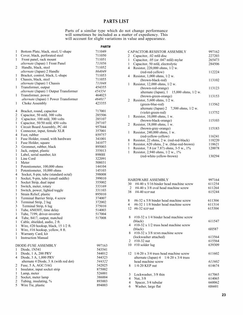
PARTS LIST
Parts of a similar type which do not change performance will sometimes be included as a matter of expediency. This will account for slight variations in value and appearance.
PART# 1 Bottom Plate, black, steel, U-shape 711049 1 Cover, black, perforated steel 711050 1 Front panel, rack mount 711051 alternate (Japan) 1 Front Panel 711056 2 Handle, black, steel 711052 alternate (Japan) 2 Handle 864049 1 Bracket, control, black, L-shape 711053 1 Chassis, black, steel 711055 alternate (Japan) 1 Chassis 711048 1 Transformer, output 454355 alternate (Japan) 1 Output Transformer 454354 1 Transformer, power 464023 alternate (Japan) 1 Power Transformer 464017 1 Choke Assembly 423355
4 Bracket, round, capacitor 717001 2 Capacitor, 50 mfd, 300 volts 285506 2 Capacitor, 100 mfd, 300 volts 285107 1 Capacitor, 50/50 mfd, 450 volts 297107 1 Circuit Board Assembly, PC-44 957044 1 Connector, input, female XLR 357001 4 Foot, rubber 859757 1 Fuse Holder, round, with hardware 341001 1 Fuse Holder, square 341077 3 Grommet, rubber, black 895003 1 Jack, output, plastic 355013 1 Label, serial number, kit 8980H 1 Line Cord 322091 1 Meter 508031 1 Potentiometer, 100,000 ohms 144104 1 Potentiometer, 10,000 ohms 145103 4 Socket, 8-pin, tube (standard octal) 398008 1 Socket, 9-pin, tube (small saddle) 399010 1 Socket Strip, dual input 355002 1 Switch, meter, rotary 333169 1 Switch, power, lighted toggle 331103 1 Strain Relief, plastic 895010 1 Terminal Barrier Strip, 4 screw 374007 3 Terminal Strip, 2 lug 372002 3 Terminal Strip, 6 lug 375010 1 Tube, 6N030T, time delay 514003 1 Tube, 7199, driver-inverter 517004 4 Tube, 8417, output, matched 517008 1 Cable, shielded, audio, 2 ft. 1 Wire, #20 hookup, black, 15 1/2 ft. 1 Wire, #16 hookup, yellow, 8 ft. 1 Warranty Card, kit 1 Instruction Manual
DIODE-FUSE ASSEMBLY 997163 1 Diode, 1N541 543541 1 Diode, 1 A, 200 PRV 544012 4 Diode, 3 A, 1,000 PRV 544323 alternate 4 Diode, 3 A (with red dot) 544322 2 Fuse, 5 A, AGC/3AG 342025 1 Insulator, input socket strip 875002 1 Lamp, meter 526001 2 Socket, meter lamp 386004 2 Tubing, insulating, % 893003 5 Wire Tie, plastic 894003
CAPACITOR-RESISTOR ASSEMBLY 997162 2 Capacitor, .02 mfd disc 227203 1 Capacitor, .05 (or .047 mfd) mylar 265473 1 Capacitor, 50 mfd, electrolytic 284506 4 Resistor, 220,000 ohms, 1/2 w. (red-red-yellow) 112224 4 Resistor, 1,000 ohms, 1/2 w. (brown-black-red) 113102 1 Resistor, 12,000 ohms, 1/2 w. (brown-red-orange) 113123 alternate (Japan), 1 15,000 ohms, 1/2 w. (brown-green-orange) 113153 2 Resistor, 5,600 ohms, 1/2 w. (green-blue-red) 113562
alternate (Japan) 2 7,500 ohms, 1/2 w. (violet-green-red) 113752 1 Resistor, 10,000 ohms, 1 w. (brown-black-orange) 115103 2 Resistor, 18,000 ohms, 1 w. (brown-gray-orange) 115183 1 Resistor, 240,000 ohms, 1 w. (red-yellow-yellow) 116241 8 Resistor, 22 ohms, 2 w. (red-red-black) 118220 1 Resistor, 620 ohms, 2 w. (blue-red-brown) 118621 1 Resistor, 7.8 (or 7.87) ohms, 3-5 w., 1% 120078 1 Resistor, 2,940 ohms, 1/2 w., 1% (red-white-yellow-brown) 130294
HARDWARE ASSEMBLY 997164 30 #4-40 x 5/16 binder head machine screw 611254 2 #4-40 x 3/8 oval head machine screw 611264 38 #4-40 KEP nut 615244
8 #6-32 x 5/8 binder head machine screw 611304 4 #6-32 1 1/8 binder head machine screw 611314 12 #6-32 KEP nut 615304
8 #10-32 x 1/4 binder head machine screw (black) 611547 4 #10-32 x 1/2 truss head machine screw (black) 6H587 8 #10-32 x 3/8 SEMS machine screw (lockwasher attached) 613564 2 #10-32 nut 615564 10 #10 solder lug 639309
12 1/4-20 x 3/4 truss head machine screw 611602 alternate (Japan) 4 1/4-20 x 3/4 truss head machine screw 611602 8 1/4-20 KEP nut 614674
3 Lockwasher, 3/8 thin 617065 4 Nut, 3/8 614065 4 Spacer, 3/4 tubular 660062 6 Washer, large flat 6I6601
23