The Many Facets and Complexities of 316L and the Effect … · The Many Facets and Complexities of...
7
ITSC 2015- Int. Thermal Spray Conf., May 11-14 2015, California, USA The Many Facets and Complexities of 316L and the Effect on Properties Ingrid Hauer Miller Höganäs AB, Höganäs, Sweden state and country [email protected], +46702066244 Abstract One of the most widely accepted and versatile materials used with many coating deposition methods is austenitic stainless steel 316L. This is due to the combination of good corrosion and mechanical properties that are suitable for numerous varying applications. As a result of our familiarity with 316L we assume the properties achieved will be within the expected frame as described in the literature. Deposition techniques and component size and shape have an impact on the heating and cooling variations which will then affect the microstructure of the final coating. This in turn will result in variations in the properties achieved. Some of these numerous factors such as: deposition technique, component geometry and size, impurities in the substrate and chemistry of the substrate will be considered. The influence of these factors on the microstructure and the definitive properties of 316L will be presented. Introduction Welding provides very high bond strength between deposit and substrate and can be applied in thickness greater than most other techniques; typically in the range 2-20 mm. Welding is often used for resurfacing. These processes involve application of heat to the processed component and depending on the material from which it is made and its conditions, certain precautions may need to be taken. During fusion weld surfacing, the coating material is raised to its melting point, which means that metals and alloys used for the purpose must have a melting point similar or less than the substrate materials. Exceptions of this general rule are found in friction surfacing and explosive cladding. Other coating materials with higher melting points, such as ceramics, may be applied by thermal spraying processes. The welding methods used in this investigation are PTA and laser cladding. Laser cladding utilizes a high power laser beam as a heat source for the melting and fusing of the substrate and filler materials. As the laser is a beam of electromagnetic radiation, all of the injected energy is confined within a small spot with no diffusion due to convection from hot gasses or electromagnetic forces taking place. As a result, the heat input to the part is minimised and higher welding quality and efficiency is attained. Filler metal is added in many ways with the most common being powder injection. The creation of a melt pool where a fine film of base material is melted and the filler material is injected, results in the formation of a welding bead which is strongly adhered to the substrate. The dilution in the deposit is around 5%. The high intensity of the laser beam and the associated low heat input results in minimised distortion, residual stresses and base metal degradation. Furthermore, the higher cooling rates attained result in finer microstructures and smaller heat affected zones leading to improved mechanical properties. These facts allow the processing of critical parts which could not be repaired in the past with other fuse welding techniques. This opens new opportunities for performance enhancement and cost reductions through the salvaging of parts which were previously scraped. Furthermore, the impeccable control of overlay thickness and low overlay roughness minimises the machining allowances and hence lowers the production or repair costs. The plasma transferred arc, (PTA) process uses an argon shielded tungsten arc as the source of energy. The powder is introduced into a combined arc/plasma stream to form a molten pool on the workpiece. Additionally, the arc between the workpiece and gun produces surface melting of base material and dilution of 5 to 15% in the deposit is typical. This method should not be confused with plasma spraying which used a non-transferred arc to generate the heating plasma for spraying powders. The main differences between the two methods are: - Higher heat input in PTA compared to laser, which will also result in a greater heat affected zone and higher dilution - Faster cooling rate for laser which will give a finer microstructure, resulting in higher hardness and superior wear resistance. When the same coating method is used, the final quality of the clad is depending of several factors, such as: material used for cladding, component geometry, component size, impurity size and number. The purpose of this work is to show how the different factors influence the final quality of the coating, when the stainless steel 316L is used.
Transcript of The Many Facets and Complexities of 316L and the Effect … · The Many Facets and Complexities of...

ITSC 2015- Int. Thermal Spray Conf., May 11-14 2015, California, USA
The Many Facets and Complexities of 316L and the Effect on Properties
Ingrid Hauer Miller Höganäs AB, Höganäs, Sweden state and country
[email protected], +46702066244
Abstract
One of the most widely accepted and versatile materials used
with many coating deposition methods is austenitic stainless
steel 316L. This is due to the combination of good corrosion
and mechanical properties that are suitable for numerous
varying applications. As a result of our familiarity with 316L
we assume the properties achieved will be within the expected
frame as described in the literature. Deposition techniques and
component size and shape have an impact on the heating and
cooling variations which will then affect the microstructure of
the final coating. This in turn will result in variations in the
properties achieved. Some of these numerous factors such as:
deposition technique, component geometry and size, impurities
in the substrate and chemistry of the substrate will be
considered. The influence of these factors on the
microstructure and the definitive properties of 316L will be
presented.
Introduction
Welding provides very high bond strength between deposit
and substrate and can be applied in thickness greater than most
other techniques; typically in the range 2-20 mm. Welding is
often used for resurfacing. These processes involve application
of heat to the processed component and depending on the
material from which it is made and its conditions, certain
precautions may need to be taken. During fusion weld
surfacing, the coating material is raised to its melting point,
which means that metals and alloys used for the purpose must
have a melting point similar or less than the substrate
materials. Exceptions of this general rule are found in friction
surfacing and explosive cladding. Other coating materials with
higher melting points, such as ceramics, may be applied by
thermal spraying processes. The welding methods used in this
investigation are PTA and laser cladding.
Laser cladding utilizes a high power laser beam as a heat
source for the melting and fusing of the substrate and filler
materials. As the laser is a beam of electromagnetic radiation,
all of the injected energy is confined within a small spot with
no diffusion due to convection from hot gasses or
electromagnetic forces taking place. As a result, the heat input
to the part is minimised and higher welding quality and
efficiency is attained. Filler metal is added in many ways with
the most common being powder injection. The creation of a
melt pool where a fine film of base material is melted and the
filler material is injected, results in the formation of a welding
bead which is strongly adhered to the substrate. The dilution in
the deposit is around 5%.
The high intensity of the laser beam and the associated low
heat input results in minimised distortion, residual stresses and
base metal degradation. Furthermore, the higher cooling rates
attained result in finer microstructures and smaller heat
affected zones leading to improved mechanical properties.
These facts allow the processing of critical parts which could
not be repaired in the past with other fuse welding techniques.
This opens new opportunities for performance enhancement
and cost reductions through the salvaging of parts which were
previously scraped. Furthermore, the impeccable control of
overlay thickness and low overlay roughness minimises the
machining allowances and hence lowers the production or
repair costs.
The plasma transferred arc, (PTA) process uses an argon
shielded tungsten arc as the source of energy. The powder is
introduced into a combined arc/plasma stream to form a
molten pool on the workpiece. Additionally, the arc between
the workpiece and gun produces surface melting of base
material and dilution of 5 to 15% in the deposit is typical. This
method should not be confused with plasma spraying which
used a non-transferred arc to generate the heating plasma for
spraying powders.
The main differences between the two methods are:
- Higher heat input in PTA compared to laser, which
will also result in a greater heat affected zone and
higher dilution
- Faster cooling rate for laser which will give a finer
microstructure, resulting in higher hardness and
superior wear resistance.
When the same coating method is used, the final quality of the
clad is depending of several factors, such as: material used for
cladding, component geometry, component size, impurity size
and number.
The purpose of this work is to show how the different factors
influence the final quality of the coating, when the stainless
steel 316L is used.

ITSC 2015- Int. Thermal Spray Conf., May 11-14 2015, California, USA
The differences in the coating properties are also presented
when two different methods are used: laser cladding and
plasma arc welding (PTA).
Experimental Method
The coating material used in this investigation is the austenitic
stainless steel 316L with the composition shown in Table 1.
The surfacing was made using laser cladding and PTA
methods on low alloyed carbon steel substrates.
Table 1: 316L composition.
C% Si% Fe% Cr% Ni% Mo% Mn%
316L <0.03 0.8 base 17 12 2.5 1.5
All tests were performed in the Höganäs laboratory.
The laser cladding was performed on a Coherent direct diode
laser, 4 kW, 808 nm wavelength. Substrate was 1018 steel in 3
forms and the clads were applied in a single layer. Shapes used
are as follows:
- 70 x 100 x 10 mm (w x l x t) plate
- 50 x 200 x 20 mm (w x l x t) plate
- 25 mm ID x 30 mm OD tube
Same parameters were used for all the laser cladding tests:
- Power 3kW
- Cladding speed 5 mm/s
- Feed rate 30 g/min
- Feed gas (Ar) 3 l/min
- Shield gas (Ar) 10 l/min
The PTA used was Hettiger with HP302 torch.
The PTA weld was applied on 1311 low carbon steel plate
measuring 50 x 200 x 20 mm (w x l x t).
The parameters used for the PTA tests were:
- Current: 125 A on the first layer
115 A on the second layer
- Welding speed 12 mm/s
- Feed rate 30 g/min
- Feed gas (Ar) 1 l/min
- Shield gas (95%Ar + 10%H) 12 l/min
- Plasma gas (Ar) 1,5 l/min
- Weld width 10 mm
Dilution was measured on the top layer using an XRF Niton
XL2 gun for the laser cladded coatings and EDS method for
the PTA ones.
Metallographic test samples were prepared by cutting the
samples perpendicular to the welding direction. These were
placed in a mounting press which was filled to 1/3 with a glass
fibre resin followed by 2/3 with Bakelite resin. The samples
were processed under high pressure during the heating and
cooling cycles. Finally the samples were plane ground and
polished with 9µm subsequently followed by 3µm and lastly
1µm DP (diamond polish) suspension. The etching agent used
was glyceregia which consists of 45 ml glycerol 98% (purum),
15 ml HNO3 and 30 ml HCl.
The samples were evaluated metallographically by LOM and
SEM. The hardness HV10 was measured and calculated as an
average of 7 measurements.
Results and Discussion
The pictures of the three laser coated sample together with the
microstructure can be seen in Fig. 1, 2 and 3.
Figure 1: 316 as laser coated on OD30/ID25 tube

ITSC 2015- Int. Thermal Spray Conf., May 11-14 2015, California, USA
Figure 2: 316 as laser coated on 10mm thick plate
Figure 3: 316 as laser coated on 20 mm thick plate
Each of the coatings in the previous figures show an overview
of the coatings microstructure.
The microstructure of the coatings consists of austenite and
delta ferrite. Fully austenitic stainless steels are known to be
prone to hot cracking during welding. In order to prevent the
occurrence of hot cracking, 4-10% ferrite should be present in
the finished weld. This can be achieved via laser cladding
processes due to the high cooling rate [1].
Figure 4 displays an even dendritic structure with coarser
dendrites, which have longer time to grow due to the slowest
cooling rate. This component was too small and overheated
during welding which lead to slower cooling rate compared to
the other components.
Figure 5 shows a mostly even structure, but finer due to faster
cooling rate.
In case of the largest mass component, Fig. 6, the structure
obtained was the most uneven compared to the smaller ones.
Figure 4. Dendritic structure on tube
Figure 5. Dendritic structure on the 10 mm thick plate

ITSC 2015- Int. Thermal Spray Conf., May 11-14 2015, California, USA
Figure 6. Dendritic structure on the 20 mm thick plate
More etched pictures of the different microstructures are
presented in Fig. 7, 8, and 9.
Figure 7. Microstructure of coating performed on tube
Figure 8. Microstructure of coating performed on 10 mm thick
plate
Figure 9. Microstructure of coating performed on 20 mm thick
plate
The microstructures of the coatings performed on the plates
were very similar (see Fig. 8 and 9). When the coating was
applied to the smallest component, the tube, a lower amount of
delta ferrite was obtained as a result of the lower cooling rate.
The outcome was a small hot crack in the structure which is
illustrated in Fig. 7.
The PTA and laser clad samples were compared on the 20 mm
thick plate. The microstructures are shown in Fig. 10
Figure 10. Microstructure of 316L as laser welded (top) and
PTA welded (bottom)
ITSC 2015- Int. Thermal Spray Conf., May 11-14 2015, California, USA
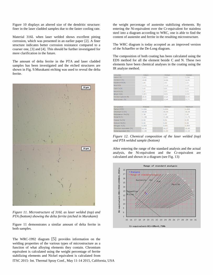
Figure 10 displays an altered size of the dendritic structure:
finer in the laser cladded samples due to the faster cooling rate.
Material 316L when laser welded shows excellent pitting
corrosion, which was presented in an earlier paper [2]. A finer
structure indicates better corrosion resistance compared to a
coarser one, [3] and [4]. This should be further investigated for
more clarification in the future.
The amount of delta ferrite in the PTA and laser cladded
samples has been investigated and the etched structures are
shown in Fig. 9.Murakami etching was used to reveal the delta
ferrite.
Figure 11. Microstructure of 316L as laser welded (top) and
PTA (bottom) showing the delta ferrite (etched in Murakami)
Figure 11 demonstrates a similar amount of delta ferrite in
both samples.
The WRC-1992 diagram [5] provides information on the
welding properties of the various types of microstructure as a
function of what alloying elements they contain. Chromium
equivalent is calculated using the weight percentage of ferrite
stabilizing elements and Nickel equivalent is calculated from
the weight percentage of austenite stabilizing elements. By
entering the Ni-equivalent over the Cr-equivalent for stainless
steel into a diagram according to WRC, one is able to find the
content of austenite and ferrite in the resulting microstructure.
The WRC diagram is today accepted as an improved version
of the Schaeffer or the De-Long diagram.
The composition of both coating has been calculated using the
EDS method for all the element beside C and N. These two
elements have been chemical analyses in the coating using the
IR analyze method.
Figure 12. Chemical composition of the laser welded (top)
and PTA welded sample (bottom)
After entering the range of the standard analysis and the actual
analysis, the Ni-equivalent and the Cr-equivalent are
calculated and shown in a diagram (see Fig. 13)

ITSC 2015- Int. Thermal Spray Conf., May 11-14 2015, California, USA
Figure 13. WRC-1992 diagram for the laser welded sample
(top) and PTA welded sample (bottom) showing the
percentage of delta ferrite.
The WRC diagram shows the same amount of delta ferrite in
both coatings at approximately 4%. Despite increased cooling
rate in the laser process, the differences in the chemical
compositions, lead to the same percentage of delta ferrite in
both cases.
As discussed earlier, dilution is greater in the PTA process due
to a higher amount of heat input during the process.
The dilution was also measured on the top layer deposition in
both cases and the results were:
4% for the laser cladded sample
9% for the PTA welded sample.
The dilution is also illustrated in Fig. 14, by using the line
analyse from the substrate through the coating.
Figure 14. Line analysis of the laser coating (top) and PTA
coating (bottom)
As it can be seen in Fig. 14, a steeper curve is obtained when
the laser process is used.
The hardness has been measured and a higher hardness was
obtained in the laser cladded sample, 166 HV10, compared to
the PTA laser welded sample, 150 HV10. The difference is
due to the different cooling rates between the two methods but
also as a result of composition transformation due to higher
dilution in the PTA sample.
The impurities in the substrate can influence the properties of
the final coating even in small quantities.
A 316L coating was applied on the low Carbon steel
component of two different qualities: one with 0,28%Cu and
another one containing 2% Cu.
The dilution was measured in both cases and following results
were obtained:
- Low C steel 0,28%Cu dilution 5%
- Low C steel 2%Cu dilution 11%
This proves that even minor variations in trace elements in the
substrate can result in different properties of the final coating.
Conclusions
Despite following identical setup procedure, the final
quality of the clad is dependent on several factors:
• Material used for cladding on component
• Component geometry
• Component size
• Size & number of impurities in the substrate
The geometry of the component can influence the
cladding pattern needed in order to get a good quality
clad
The final structure of the clad is a function of the
cooling rate, which is dependent on the component
size for the same process parameters
A finer structure is obtained when laser cladding
process is used compared to the PTA process. This
Si Cr
Ni Mn
Fe Mo

ITSC 2015- Int. Thermal Spray Conf., May 11-14 2015, California, USA
leads to higher hardness for the laser coating versus
the PTA coating.
Delta ferrite formed during the welding process is
critical in order to obtain a crack free structure
Dilution can be influenced by the chemistry of the
substrate.
Acknowledgments
The author would like to thank Mr. Kari Westerling and Mrs.
Barbara Maroli for their vital contribution to the successful
outcome of this work.
References
[1] ASM Speciality Handbook, Stainless Steels. ASM
International – The Materials Information Sociaty
[2] Kampanis, Nicholas and Hauer, Ingrid. “Propeller Shaft
Repair for a Large Ferry with the Aid of Laser Cladding”,
Surabaya, Indonesia : s.n., 2010. ICSOT Conference.
(Roussakis SA, Hellas, Höganäs AB, Sweden).
[3] Li, Zhen, “Influence of Cold Work and Grain Size on the
Pitting Corrosion Resistance of Ferritic Stainless Steel”,
Seattle : Minerals, Metals and Materials Society/AIME, 2010.
TMS 2010 Annual Meeting and Exhibition.
[4] Carvalho, Felipe Leal, “Influence of Austenitic Grain Size
on the Stress Corrosion Cracking Resistance of Steel Applied
in Sour Service Environments”, Brasil : 61st Annual ABM
International Congress, 2006.
[5] http://www.migweld.de/english/home.


![EffectofColdWorkingontheDrivingForceoftheCrackGrowth ... · 2020. 8. 25. · Mechanical parameters 600 alloy 316L-CW0 316L-CW10 316L-CW20 Oxide film Yield strength (MPa) 436 [11]](https://static.fdocuments.net/doc/165x107/60b30c27e742c032c66e8a0b/effectofcoldworkingonthedrivingforceofthecrackgrowth-2020-8-25-mechanical.jpg)