inelastic buckling tests of ring-stiffened cylinders under hydrostatic ...

Steel Structures 7 (2007) 129-138 www.kssc.or.kr
The Local Web Buckling Strength of Stiffened Coped Steel I-Beams
Michael C.H. Yam1,*, Angus C.C. Lam2, Feng Wei1,3 and K. F. Chung4
1Department of Building & Real Estate, The Hong Kong Polytechnic University, Hung Hom, Kowloon, Hong Kong2Department of Civil & Environ. Engineering, Faculty of Science & Technology, University of Macau,
P.O. Box 3001, Macau (Currently, PhD student at the University of Alberta, Edmonton, Alberta, Canada)3Department of Civil Engineering, Chongqing University, Chongqing, 400045, China
4Department of Civil & Structural Engineering, The Hong Kong Polytechnic University, Hung Hom, Kowloon, Hong Kong
Abstract
In steel construction the flange of a steel I-beam is usually coped to allow clearance at the connection. The presence of acope in a beam will reduce the strength of the beam in the coped region. Local web buckling at the coped region may occurwhen the cope length is long and/or the cope depth is large, provided that lateral-torsional buckling of the beam is prevented.Previous research recommended the provision of stiffeners at the coped region to improve the local web buckling strength ofcoped I-beams although no experimental evidence was provided to support the recommendation. In order to verify suchrecommendation, an experimental and numerical investigation of coped I-beams with stiffeners at the coped region wasconducted and reported in this paper. The study showed that current recommendations did not consider the web distortionproperly, i.e. local web buckling could not be prevented efficiently if only horizontal stiffeners were provided at the copedregion. Both the test and the numerical results showed that the horizontal stiffeners at the cope displaced laterally due to grossweb distortion. Based on the results of the parametric study of coped beams with different configurations of horizontal andvertical stiffeners, it was found that for cope depth to beam depth ratio (dc/D) ≥ 0.3, both horizontal and vertical stiffeners arerequired in order to prevent local web buckling at the cope region. A preliminary recommendation for the design of copedbeams with both horizontal and vertical stiffeners was proposed according to the key findings of the investigation.
Keywords: steel I-beams, copes, local buckling, stiffeners, strengthening, tests, finite element analysis
1. Introduction
In steel construction, when beams are connected to
girders at the same elevation, beam flanges must be coped
to provide sufficient clearance for proper attachments to
supports as shown in Fig. 1. The cope can be at the top,
the bottom, or at both flanges. When a beam is coped, the
lateral-torsional buckling capacity of the beam, the shear
capacity and the local web buckling capacity at the coped
regions can be affected (Cheng, 1993). In addition, if the
beam is not properly braced, the coped beam can fail in
lateral-torsional buckling mode with much reduced
strength (Cheng and Yura, 1988; Cheng and Snell, 1991,
and Lam et al., 2000). However, if lateral bracing is
provided at the vicinity of the copes or the cope length is
sufficiently long, shear tearing or local web buckling at
the coped region may occur. Investigation on the block
shear tearing behavior at copes was conducted by
Birkemoe et al. (1978) and Ricles et al. (1980). Cheng
and Yura (1986) carried out both experimental and
analytical studies on the local web buckling of coped I-
beams. The effects of cope length and cope depth on the
local web buckling capacities of coped beams were
investigated. Design formulas were proposed for the local
web buckling strengths of coped I-beams while improvement
to the design formulas was provided by Yam, et al.
(2003). In Cheng and Yura’s original study (1984) on the
local web buckling of coped beams, possible strengthening
of coped region was studied. They recommended using
stiffeners at the coped region to improve the local web
buckling strength of coped I-beams. Three reinforcing
details as shown in Fig. 2 are recommended. Reinforcing
details of type (a) and (b) are recommended for all rolled
sections or sections with a beam depth to web thickness
ratio less than 60. Detail of type (c) is recommended for
thin web members with a web slenderness ratio greater
*Corresponding authorTel: +852-2766-4380; Fax: +852-276-4513Email: [email protected] Figure 1. Typical top flange coped I-beam.

130 Michael C.H. Yam et al.
than 60. However, no experimental evidence was provided
so far to validate the recommendation. Therefore, in order
to verify the strengthening details recommended by
Cheng and Yura (1984), an experimental study of coped
I-beams with horizontal stiffeners of type (b) at the cope
was conducted and reported here. Three full-scale tests of
top flange coped steel I-beams with dc/D equal to 0.3
were conducted, and it should be noted that while
horizontal stiffener were provided at the cope of two
specimens, no horizontal stiffener was provided to the
other. Finite element analyses of all the test specimens are
also presented in this paper.
2. Test Program
Three tests were conducted to study the local web
buckling (LWB) behavior of top flange coped I-beams
with horizontal stiffeners. Welded beams with cross
section dimensions closely similar to UB 406 × 140 × 39
(Steelwork 1990) were used as the test specimens. These
UB sections are equivalent to the U.S. section W16 × 26.
The nominal cope dimensions of the beams together with
the measured dimensions (in bracket) are shown in Table
1. A single end plate was welded perpendicular onto the
web of the coped beam end to be connected to the reaction
wall. The sizes of all the end plates were carefully
designed to provide sufficient shear strengths and at the
same time minimized the in-plane rotational stiffness in
order to simulate a simply supported boundary condition
for the coped beam end. It was proposed by Cheng et al.
(1984) that in order to prevent local web buckling of
coped beams, horizontal stiffeners with extension of
stiffener length, LR, (Fig. 2) of not less than dc (LR ≥ dc)
should be provided at the cope. Hence, two specimens,
406d03sa and 406d03sb with two types of stiffeners
(Details A and B) with a minimum extension of LR equal
to dc were investigated, as shown in Fig. 3. The length of
stiffener type A was equal to the cope length plus the
cope depth whereas the length of stiffener type B was
equal to the cope length only and with a clearance equal
to dc at the beam end, which was 25% shorter than
stiffener type A. It should be noted that the stiffeners
were welded on both sides of the web. The thickness of
the stiffeners was approximately equal to the thickness of
the flange while the width of the stiffeners in one side
was equal to half of the width of the flange. In addition
to the two specimens with horizontal stiffeners, one
specimen (406d03) without stiffeners at the cope was also
tested. Therefore, the local web capacity of the coped
region with and without stiffeners could be compared.
Tension coupons were prepared from all the test beams in
the longitudinal direction and tested according to ASTM
standard (A370-97a). The average tensile yield strength
of the web was 343 MPa and the average elastic modulus
of the web was 216,600 MPa.
The test setup is shown schematically in Fig. 4. Load
was applied to the beam vertically upward. The load
position was chosen not only to produce failure in the
coped region but also to minimize the effect of the load
itself on the stress distribution in the coped region. The
Figure 2. Web reinforcement details for coped beams.
Figure 3. Coped beams with horizontal stiffeners.
Table 1. Dimensions of test specimens
Specimendc
(mm)D
(mm)B
(mm)tw
(mm)tf
(mm)c
(mm)dc/D
406d03 119.4 (117) 398 (398) 142 (143) 6.0 (6.0) 8.0 (8.0) 342.9 (343) 0.3 (0.3)
406d03sa 119.4 (119) 398 (396) 142 (143) 6.0 (6.0) 8.0 (8.0) 342.9 (343) 0.3 (0.3)
406d03sb 119.4 (120) 398 (396) 142 (143) 6.0 (6.0) 8.0 (8.0) 342.9 (334) 0.3 (0.3)
Model 1 119.4 398 142 6.0 8.0 342.9 0.3 (0.3)
Model 2 119.4 398 142 6.0 8.0 497.5 0.3 (0.3)
Values in bracket indicate measured dimensionsdc = coped depth, D = beam depth, B = flange width, tw = web thickness, tf = flange thicknessc = cope length

The Local Web Buckling Strength of Stiffened Coped Steel I-Beams 131
distance from the load position to the end plate was 995
mm, i.e. 2.5D approximately. Lateral bracings were
provided at the load position, the pin support and the end
of the cope on the flanges in order to prevent lateral
movement. Since local web buckling was a local behavior,
the other end of each specimen was used for another test
as a new specimen once the end that was connected to the
strong wall failed.
Load was applied quasi-statically and was controlled by
an electro-hydraulic servo controller. At the far end
support, load cell was used to measure the reaction force.
The magnitude of the applied load and the far end reaction
force were recorded and transferred to a data acquisition
system. To measure the in-plane deflections, dial gauges
were set up at the load position and at the end of the cope.
Another set of dial gauges was set up on the web to
measure the lateral deflection of the web. In addition,
longitudinal strain gauges were mounted onto the web at
the cope to measure the strain distribution of the web at the
cope as well as to detect any buckling of the web.
The test procedure was generally the same for all the
tests. The loading procedure was divided into two stages.
In the first stage, load was applied by controlling the
magnitude of the loading (i.e. load control). After the
applied load reached approximately 50% of the expected
maximum load, load was applied by controlling the
magnitude of the vertical deflection at the loaded point
(i.e. stroke control). At this stage, the vertical deflection
at the loaded point was applied in increments. Load was
applied until the post-buckling curve was obtained.
3. Test Results
The failure mode of the specimen without stiffeners at
the cope was identified to be local web buckling at the
cope region as shown in Fig. 5. The failure mode of the
specimens with horizontal stiffeners was identified to be
web distortion occurring at the web region between the
top flange (the beam was loaded upside down) and the
horizontal stiffener which exhibited significant lateral
displacement (Fig. 5). The ultimate loads of the specimens
(PTest) are summarized in Table 2. The load versus in-
plane vertical deflection curves (Fig. 6) show that linear
behavior exists before buckling. This probably indicates
that the specimens do not experience significant yielding
prior to instability failure. The load deflection behaviors
of these specimens were similar in that no sudden drop of
loading was observed and the post buckling behavior was
generally stable. It can be seen from the figure that the
applied load decreased gradually when the vertical
deflection of the loaded point increased during unloading.
The test results showed that the ultimate loads of the
specimens with horizontal stiffeners were larger than that
of the specimen without stiffeners by about 50%.
Meanwhile, the ultimate load of the specimen with
stiffener type B was almost the same as that of the
specimen with stiffener type A even though the length of
type A stiffener was 25% longer than that of type B
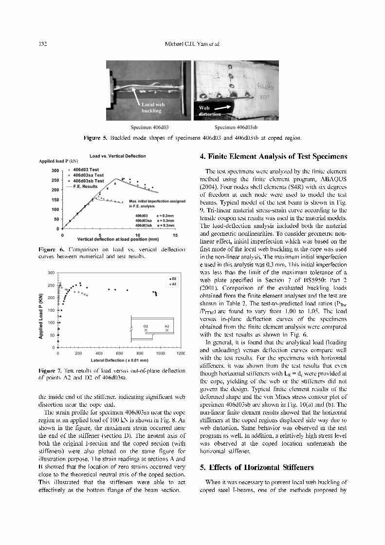
stiffener. The load versus out-of-plane displacement for
specimen 406d03sa is shown in Fig. 7. The figure shows
that a significant out-of-plane displacement occurred near
Figure 4. Test setup.
132 Michael C.H. Yam et al.
the inside end of the stiffener, indicating significant web
distortion near the cope end.
The strain profile for specimen 406d03sa near the cope
region at an applied load of 100 kN is shown in Fig. 8. As
shown in the figure, the maximum strain occurred near
the end of the stiffener (section D). The neutral axis of
both the original I-section and the coped section (with
stiffeners) were also plotted on the same figure for
illustration purpose. The strain readings at sections A and
B showed that the location of zero strains occurred very
close to the theoretical neutral axis of the coped section.
This illustrated that the stiffeners were able to act
effectively as the bottom flange of the beam section.
4. Finite Element Analysis of Test Specimens
The test specimens were analyzed by the finite element
method using the finite element program, ABAQUS
(2004). Four nodes shell elements (S4R) with six degrees
of freedom at each node were used to model the test
beams. Typical model of the test beam is shown in Fig.
9. Tri-linear material stress-strain curve according to the
tensile coupon test results was used in the material models.
The load-deflection analysis included both the material
and geometric nonlinearities. To consider geometric non-
linear effect, initial imperfection which was based on the
first mode of the local web buckling at the cope was used
in the non-linear analysis. The maximum initial imperfection
e used in this analysis was 0.3 mm. This initial imperfection
was less than the limit of the maximum tolerance of a
web plate specified in Section 7 of BS5950: Part 2
(2001). Comparison of the evaluated buckling loads
obtained from the finite element analyses and the test are
shown in Table 2. The test-to-predicted load ratios (PTest
/PFEM) are found to vary from 1.00 to 1.05. The load
versus in-plane deflection curves of the specimens
obtained from the finite element analysis were compared
with the test results as shown in Fig. 6.
In general, it is found that the analytical load (loading
and unloading) versus deflection curves compare well
with the test results. For the specimens with horizontal
stiffeners, it was shown from the test results that even
though horizontal stiffeners with LR = dc were provided at
the cope, yielding of the web or the stiffeners did not
govern the design. Typical finite element results of the
deformed shape and the von Mises stress contour plot of
specimen 406d03sb are shown in Fig. 10(a) and (b). The
non-linear finite element results showed that the horizontal
stiffeners at the coped regions displaced side way due to
web distortion. Same behavior was observed in the test
program as well. In addition, a relatively high stress level
was observed at the coped location underneath the
horizontal stiffener.
5. Effects of Horizontal Stiffeners
When it was necessary to prevent local web buckling of
coped steel I-beams, one of the methods proposed by
Figure 5. Buckled mode shapes of specimens 406d03 and 406d03sb at coped region.
Figure 6. Comparison on load vs. vertical deflectioncurves between numerical and test results.
Figure 7. Test results of load versus out-of-plane deflectionof points A2 and D2 of 406d03sa.

The Local Web Buckling Strength of Stiffened Coped Steel I-Beams 133
Cheng et al. (1984) was to provide horizontal stiffeners at
the cope. However, it was shown from the test results that
the horizontal stiffeners at the cope might displace laterally
due to web distortion when the cope depth was too large.
Therefore, in the analytical study, two different types of
stiffeners were examined. The first type of stiffeners only
included horizontal stiffeners while the second type of
stiffeners included both horizontal and vertical stiffeners
(Fig. 11). The use of the vertical stiffeners was believed
to be able to prevent the side way movement of the web
and the horizontal stiffeners. It was shown previously in
the test program that the provision of stiffener type B,
which was 25% shorter than the full length stiffener
(stiffener type A) did not decrease the ultimate load.
Therefore, in the first study, stiffener type B was used as
the basic model. Two models of stiffener type B with
different cope lengths, c = 342.9 mm (c/D = 0.86) and c =
497.5 mm (c/D = 1.25) were studied, of which the cope
depth dc was equal to D/3. The dimensions of the
analytical models, which were similar to that of specimen
406d03sb, are shown in Table 1. The yield strength and
the modulus of elasticity of the steel for the model were
assumed to be 350 MPa and 205,000 MPa, respectively.
The length of the horizontal stiffeners was extended (by
extending LR) in order to increase the local web buckling
capacity of the coped section. Typical finite element
model is shown in Fig. 12. The distance between the
point load and the cope end is 2.5D where D is the beam
depth. Lateral bracings were provided at the load position,
the pin support and the end of the cope on the top and the
bottom flanges. Elastic buckling analysis was carried out
first in order to obtain the first buckling mode shape of
the coped I-beam. Then, non-linear analysis that incorporated
the first buckling mode shape with a maximum initial
imperfection equal to 0.15 mm (= 2.5% of tw) as the
initial geometry of the cope I-beam, was carried out. The
results are shown in Table 3. For the model with c/D =
Figure 8. Test results of strain profile for specimen 406d03sa near the cope.
Figure 9. Finite element model of a stiffened coped I-beam.
Table 2. Comparison between test results and finite element results
Specimen PTest (kN) RTest (kN) PFEM (kN) RFEM (kN) PTest / PFEM
406d03 167.9 111.9 159.6 106.4 1.05
406d03sa 258.1 172.1 258.2 172.1 1.00
406d03sb 259.8 173.2 258.3 172.2 1.01
PFEM-ultimate load from the finite element analysis

134 Michael C.H. Yam et al.
0.86, the extension of horizontal stiffeners (LR) was
assigned to vary from dc to 5.5dc (119.4 to 656.7mm). It
can be seen from Table 3 that when LR was equal to 5.5dc,
the increase in the ultimate reaction force RFEM, was about
28%, when compared with that of the specimen with LR
= dc. For the model with c/D = 1.25, it can be seen from
Table 3 that when LR = 4dc, the increase in the ultimate
reaction force RFEM, was about 18%, when compared with
that of the specimen with LR = dc. In fact, for both cases,
the ultimate reaction forces RFEM, with the longest horizontal
stiffeners were still significantly lower than their
corresponding yield loads (first yield) at the junction of
the coped and the un-coped sections. Hence, it is
concluded that increasing the length of horizontal stiffeners
might not increase the local web buckling capacity of
coped beam efficiently. This result contradicted with the
recommendation proposed by Cheng et al. (1984) which
stated that yielding would control the capacity of the
coped section if extensions of horizontal stiffeners with a
length of not less than the depth of cope (dc) were
provided at the cope. The reason for this disagreement is
that Cheng et al. (1984) used in their study a beam
section with a larger dc/D ratio of 0.5, as opposed to 0.3
in the present study. Hence, the yield moment capacity of
the stiffened coped section was quite small. Therefore,
the local buckling capacity of stiffened coped sections
could be easily larger than its corresponding yield moment
capacities and hence, the horizontal stiffeners were effective
in strengthening the coped sections with large cope depths.
6. Effects of Horizontal and Vertical
Stiffeners
Since it was found that increasing the length of horizontal
stiffeners did not increase the local web buckling capacities
of coped beams efficiently, it was decided to provide
Figure 10. Finite element results of specimen 406d03sb.
Figure 11. Two different types of stiffeners at the cope.

The Local Web Buckling Strength of Stiffened Coped Steel I-Beams 135
vertical stiffeners together with horizontal stiffeners at the
cope based on the observed failure mode of the test
specimens. For the model with horizontal and vertical
stiffeners, a minimum extension of horizontal stiffeners,
i.e. LR = dc, was used (same as the type B stiffener) and
the length of vertical stiffeners was assigned to vary from
zero to 238.8 mm (0 to 2dc). The finite element results are
shown in Table 4. The general failure mode of the coped
beams stiffened by both horizontal and vertical stiffeners
was still sideway displacement of the horizontal stiffeners
as shown in Fig. 13. However, the horizontal stiffeners
were anchored by the vertical stiffeners, and therefore,
rotation of the horizontal stiffeners about the longitudinal
axial of the vertical stiffeners occurred as illustrated in
Fig. 13.
For the model with c/D = 0.86, it can be seen that when
vertical stiffeners with a length equal to the cope depth
(Ly = dc) was used together with the horizontal stiffeners
Figure 12. Finite element model of coped I-beam with stiffeners.
Figure 13. Buckled mode shape of coped I-beam withboth horizontal and vertical stiffeners.
Table 3. Effects of providing horizontal stiffeners
c/D = 0.86 c/D = 1.25
LR (mm) LR / dc RFEM (kN) LR (mm) LR / dc RFEM(kN)
119.4 1 173.0 119.4 1 161.0
358.2 3 189.4 238.8 2 162.0
417.9 3.5 194.6 358.2 3 170.8
537.3 4.5 206.2 477.6 4 189.6
656.7 5.5 219.5
Table 4. Effects of providing horizontal and vertical stiffeners (LR = dc)
c/D = 0.86 c/D = 1.25
Ly (mm) Ly / dc RFEM (kN) Ly (mm) Ly / dc RFEM (kN)
0 0 173.0 0 0 161.0
119.4 1 217.0 119.4 1 172.0
238.8 2 226.0 238.8 2 178.0
382.0 3.2 183.0

136 Michael C.H. Yam et al.
of a minimum extension (LR = dc), the ultimate load of
the coped section was increased by 25%, when compared
with the one with horizontal stiffeners (LR = dc) only. On
the other hand, the ultimate load of the beam with both
horizontal and vertical stiffeners (Ly = dc and LR = dc) was
15% higher than that of the beam with only horizontal
stiffeners of a length equal to 3dc. When the length of the
vertical stiffeners was increased to 2dc (= 238.8 mm), the
corresponding reaction was increased to 226 kN. This
reaction force was about 31% larger than that of the
model with only horizontal stiffeners of LR = dc. Although
this reaction force was only 3% larger than the reaction
force of the model with horizontal stiffener LR = 5.5dc,
about 45% less of the stiffener material was used in the
latter model, and of course, this would also reduce the
length of welding.
For the model with a longer cope length (c/D = 1.25),
the results of the ultimate reaction force with horizontal
stiffeners (LR = dc) and vertical stiffeners (Ly = dc to 3.2dc)
are shown in Table 4. It can be seen that when the vertical
stiffeners were provided for approximately the whole
depth of the beam (Ly = 3.2dc), the ultimate reaction force
was 183 KN which was about 14% larger than that of the
specimen with horizontal stiffeners only (LR = dc). In addition,
for longer cope length, increasing the length of vertical
stiffeners did not increase the ultimate capacity of the
coped section significantly when LR = dc was provided.
Meanwhile, this reaction force was still lower than the
reaction force corresponding to the yield moment
capacity and the shear yielding of the web at the coped
section. Hence, it was decided to conduct further study on
the effects of varying the lengths of both the horizontal
and the vertical stiffeners in order to achieve the plastic or
at lease the first yielding moment capacity of the coped
section, or the shear yielding resistance of the web.
The local web buckling capacity of the beam with c/D
= 1.25 and dc/D = 0.3 was studied with various combinations
of the length of horizontal and vertical stiffeners. The
value of LR/dc was varied from 1 to 4 while that of Ly/dc
was varied from zero to 3.2. Non-linear finite element
analysis was carried out, and the results are shown in
Table 5. By using the ultimate reaction force of the model
with only horizontal stiffeners as the reference value (LR/
dc = 1 and Ly/dc = 0, Rref = 161 kN), the ratios of the
ultimate reaction force to the reference value versus Ly/dc
with various LR/dc ratios are shown in Fig. 10. The figure
illustrates that with a fixed value of LR, the ultimate
reaction force increased as the length of Ly increased.
Meanwhile, it is also noted that the rate of increase in the
ultimate reaction force was different for different values
of LR. For Ly = 3.2dc, the local web buckling capacity of
the cope section with LR = 3dc was about 10% larger than
that of the specimen with LR = 2dc. However, when LR
was larger than 3dc, the increase in the local web buckling
capacity of the coped section became insignificant. The
increase in the ultimate load capacity was about 1.4%
when LR was increased from 3dc to 4dc with Ly = 3.2dc.
On the other hand, it can also be seen that providing
vertical stiffeners could increase the local web buckling
capacity of coped section significantly, especially when
Ly was increased from zero to dc and LR/dc ≥ 2.
In order to obtain a good combination of the lengths of
the horizontal and the vertical stiffeners for the best
improvement in the local web buckling capacity of the
coped section, the ratio of the ultimate reaction force to
the reference value (RFEM/Rref) is plotted against the ratio
(LR + Ly)/dc as shown in Figs. 14 and 15. Both figures
show that when the total length of the stiffeners, i.e. the
length of horizontal stiffeners plus the length of vertical
stiffeners, was maintained the same, the provision of both
vertical and horizontal stiffeners simultaneously was more
efficient than extending the length of horizontal stiffeners
only. Obvious increase in the local web buckling capacity
of the coped section was obtained when a minimum
length of vertical stiffeners (Ly = dc) was provided (point
Table 5. Effects of providing horizontal and vertical stiffeners in specimen with c/D =1.25 and LR = dc, 2dc, 3dc and 4dc
RFEM (kN)
LR / dc Ly / dc = 0 Ly / dc = 1 Ly / dc = 2 Ly / dc = 3.2
1 161.0 172.0 178.0 183.0
2 162.0 195.9 201.4 204.6
3 170.8 207.0 216.8 222.0
4 189.6 223.3 226.0 226.0
Figure 14. Effects of total length of stiffeners (LR + Ly)on the local web capacity of coped section (c/D = 0.86and dc/D = 0.3).

The Local Web Buckling Strength of Stiffened Coped Steel I-Beams 137
A in Fig. 14 and points A, B, C and D in Fig. 15). On the
other hand, Figure 15 shows that extending the vertical
stiffeners to the whole depth of the beam did not seem to
have significant effect in improving the local web buckling
capacity of the coped sections (points c'', d' and e' in Fig.
15). However, it should be noted that the improved local
web buckling strength of the coped section was still lower
than the reaction forces corresponding to the yield
moment capacity and the shear yielding resistance of the
web at the cope.
7. Summary and Conclusions
The local web buckling behavior of coped I-beam with
stiffeners in the coped region was investigated both
experimentally and numerically. In the experimental
program, three full-scale tests of the local web buckling
strengths of coped steel I-beams were carried out. Two of
them were used to study the effects of horizontal
stiffeners while the other one was designed to investigate
the local web buckling strength of the coped sections
without stiffeners for comparison. It was shown from the
test results that web distortion occurred at the coped
section even when horizontal stiffeners were provided.
This indicated that the failure mode of the test specimens
with stiffeners was stability failure instead of material
failure. This result contradicted with the recommendation
proposed by Cheng et al. (1984) which stated that
yielding would control the capacity of the coped section
if extensions of horizontal stiffeners with a length of not
less than the depth of cope (dc) were provided at the cope.
The reason for this disagreement may lie in the fact that
the cope depth (dc) of the beam section tested by Cheng
et al. (1984) was large (dc/D = 0.5) but the one used in
this study was relatively smaller (dc/D = 0.3). On the
other hand, the test results illustrated that reducing the
length of horizontal stiffeners (up to 25% reduction of the
length) but keeping the minimal extension length equal to
dc did not decrease the local web buckling capacity of the
coped section.
A numerical study on coped beams with stiffeners at
the coped section was also carried out with the finite
element program, ABAQUS (2004). Non-linear finite
element analyses, in which the material non-linearity,
geometric non-linearity and initial imperfection were
taken into account, were conducted to study the effects of
providing horizontal stiffeners only and providing both
horizontal and vertical stiffeners on the strengths of
stiffened coped I-beams. The study was conducted with a
coped beam model (W16 × 26) with dc/D equal to 0.3
and c/D equal to 0.86 and 1.25. Based on the limited test
data and the numerical results, the following conclusions
on the effects of stiffeners are drawn:
For coped beams with horizontal stiffeners only, extending
the length of the horizontal stiffeners did not increase the
local web capacity efficiently.
Obvious increase in the local web buckling capacity of
the coped section was obtained when a minimum length
of vertical stiffeners (Ly = dc) was provided together with
horizontal stiffeners.
Extending the vertical stiffeners to the whole depth of
the beam did not have significant effect in improving the
local web buckling capacity of the coped section.
The local web buckling strength of the coped section
stiffened by both the horizontal and the vertical stiffeners
was still lower than the reaction force corresponding to
the yield moment capacity and the shear yielding
resistance of the web at the cope.
When the cope length to beam depth ratio is smaller
than 1 (c/D < 1), both the extension length of the horizontal
stiffeners (LR) and the length of the vertical stiffeners (Ly)
should not be less than dc for effective improvement on
the local web buckling strengths of coped beams.
When the cope length to beam depth ratio is larger than
1 (c/D > 1), both the extension length of the horizontal
stiffeners (LR) and the length of the vertical stiffeners (Ly)
should not be less than 2dc for effective improvement on
the local web buckling strengths of coped beams.
The study presented in this paper only provided some
preliminary conclusions and recommendations. In order
to develop a complete set of design guidelines for the
local web buckling strength of stiffened coped I-beams,
further experimental and analytical studies are required.
List of symbols
c cope length of steel I-beams
dc cope depth of steel I-beams
D total depth of steel I-beam sections
e maximum initial imperfection of beam web in
finite element analysis
h0 depth of coped section of steel I-beams
Figure 15. Effects of the total length of stiffeners (LR +Ly) on the local web capacity of coped section (c/D =1.25 and dc/D = 0.3).

138 Michael C.H. Yam et al.
LR extension length of horizontal stiffeners at the
coped region
Ly total length of vertical stiffeners at the coped
region
P concentrated load at the loading point of beam
specimens
PFEM ultimate loads of the specimens in the FE analysis
PTest ultimate loads of the specimens in the test
R ultimate reaction forces at the connection of the
coped end of beams
RFEM ultimate reaction in the FE analysis
Rref test ultimate reaction of the specimen without any
stiffener
tf thickness of the flange of the I-beams
tw thickness of the web of the I-beams
References
ABAQUS user’s manual, version 6.5 (2004). Hibbit,
Karlsson, and Sorenson, Pawtucket, R.I.
American Society for Testing and Materials (ASTM).
(1997). “A370 Standard test methods and definitions for
mechanical testing of steel products.” Philadelphia.
BS 5950 (2001) Structural use of steelwork in buildings, Part
2, British Standard Institution, London.
Cheng, J.J.R. (1993) “Design of steel beams with end
copes”, Journal of Construct Steel Research, 25: 3-22.
Cheng, J.J.R. and Snell, W.J. (1991) “Experimental study of
lateral buckling of coped beams”, Proceedings, Structural
Stability Research Council, Annual Technical Session,
Chicago, Illinois: 181-192.
Cheng, J.J.R., and Yura, J.A. (1986) “Discussion of Buckling
of coped steel beams”, Journal of Structural Division,
ASCE, 112: 201-203.
Cheng, J.J.R., Yura, J.A., and Johnson, C.P. (1984) “Design
and behavior of coped beams”, Ferguson Structural
Engineering Laboratory Report No. 84-1, Univ. of Texas
at Austin, Tex.
Lam, C.C., Yam, M.C.H. and Iu, V.P. (1998) Analytical
study of the elastic lateral torsional buckling of coped I-
beam, FST Report No. CE-1998-02(ST), Faculty of
Science and Technology, University of Macau.
Ricles, J. M. and Yura, J. A. (1980). “The behavior and
analysis of double-row bolted shear web connections.”
Phil. M. Ferguson Structural Engineering Laboratory
Thesis No. 80-1, Univ. of Texas at Austin, Tex.
Steelwork Design Guide to BS 5950: Part 1: 1990, Volume
1 Section properties member capacities, 2001, The Steel
Construction Institute, UK.
Yam, M.C.H., Lam, A.C.C., Iu, V.P. and Cheng, J.J.R.
(2003) “Local Web Buckling Strength of Coped Steel I-
beams”, Journal of Structural Engineering, ASCE, Vol.
129, No.1, pp3-11.
Birkemore, P.E. and Gilmor, M.I. (1978). “Behavior of
bearing critical double angle beam connections.”
Engineering Journal, 15(4):109-115.
Cheng, J.J.R., and Yura, J.A. (1986) “Local web buckling of
coped beams”, Journal of Structural Division, ASCE,
112:2314-2331.
Lam, C.C., Yam, M.C.H., Iu, V.P. and Cheng, J.J.R. (2000)
“Design for lateral torsional buckling of coped I-beams”,
Journal of Constructional Steel Research, Vol. 54, No.3,
423-443.