The Little Mermaid - marine techmarinetech.org/files/marine/files/ROV Competition/2015 files...The...
22
The Little Mermaid St. John’s, Canada 2015 Aarhus University - Denmark Instructor: Claus Melvad Members: Poul Brix Christensen CEO and co-pilot Dennik Dan Ringgaard CEO and pilot Jens Brix Christensen Engineer
Transcript of The Little Mermaid - marine techmarinetech.org/files/marine/files/ROV Competition/2015 files...The...

The Little Mermaid
St. John’s, Canada 2015
Aarhus University - Denmark
Instructor: Claus Melvad
Members: Poul Brix Christensen
CEO and co-pilot
Dennik Dan Ringgaard
CEO and pilot
Jens Brix Christensen
Engineer

The Little Mermaid
P a g e 2 | 21
1 Abstract This report describes the construction of the ROV(Remote Operated Vehicle), The Little Mermaid. The
ROV is built for an underwater ROV competition held in Canada. Many aspects of the nature have influence
on the final design. For example the pressure rises the deeper the ROV goes and this report describes how to
overcome such obstacles in the design. The purpose of an underwater ROV is to complete tasks underwater.
No matter the purposes, most factors are the same. Maneuverability, vision and stability are all key factors
for the design. This paper accounts for how both the mechanical, electric and software aspects have to
interact, as well as how people need to work together as a team. The project will end up having a fully
functional ROV, by making strategic design choices with an engineering approach.
2 Presentation This report is an outcome of a four-month study with focus on competing in the annual MATE ROV
competition. The project is related to a bachelor project at Aarhus University, Denmark, with focus on
building a ROV. This report introduces some of the key factors and components that are used when
constructing such a vehicle. The project team consist of three mechanical engineer students, all from the
Aarhus University School of Engineering.
2.1 Introduction
Humans are created to live on land, for this reason we have lungs to breathe. We can for a short while, exist
under water, but the competences we have on land is not the same when in water. The water is in fact not
where we belong. Therefore, it is much easier for us to investigate and operate on land. With more than 70%
of the Earth’s surface covered with water, there is a lot of nature that are still unknown to us. Well, it has not
stopped us from trying to investigate some places where we have difficulties to survive. We simply adapt to
the environment by making suits. We can walk on the moon with a space suit and we can swim under water
with a diving equipment. However, there is limits for humans even in a suit. A solution is therefore to send a
robot. We can send a space car to the moon and it can stay there for years, and we can build a ROV that can
go to cold water at the North Pole and stay there for hours. There are many things we still do not know about
the nature, therefore it is interesting to investigate.
2.2 Specs and Scope
The specifications for the project is set by MATE(Marine Advanced Technology Education Center). There
are several requirements, which all can be read in the Ranger manual, if more information is sought.
Listed below is some of the specifications this project must fulfil regarding the design:
Max depth: 10m
Temperature: -2/40˚C
Max pressure: 2bar
Max gripper weight: 20N
The project was started on 1st of February 2015 and has the first deadline in beginning of May. This means
there is a tight timeframe for the project. Therefore, the project is managed with project tools in order to
meet the deadline. This also mean that components and systems that are already waterproof, is preferred.

The Little Mermaid
P a g e 3 | 21
Table of Contents 1 Abstract ..................................................................................................................................................................... 2
2 Presentation ............................................................................................................................................................... 2
2.1 Introduction ....................................................................................................................................................... 2
2.2 Specs and Scope ................................................................................................................................................ 2
Main Design ...................................................................................................................................................................... 4
3 ROV design ............................................................................................................................................................... 6
3.1 General .............................................................................................................................................................. 7
3.2 Chassis .............................................................................................................................................................. 7
3.3 Thruster ............................................................................................................................................................. 8
3.4 Case ................................................................................................................................................................... 8
3.5 Connectors ........................................................................................................................................................ 8
3.6 myRIO ............................................................................................................................................................... 8
3.7 Controller .......................................................................................................................................................... 8
3.8 Gripper .............................................................................................................................................................. 9
3.9 Float .................................................................................................................................................................. 9
3.10 Weight adjustment .......................................................................................................................................... 10
3.11 Tether .............................................................................................................................................................. 10
3.12 Tilt ................................................................................................................................................................... 11
4 CFD ......................................................................................................................................................................... 12
5 Electric .................................................................................................................................................................... 14
6 Software .................................................................................................................................................................. 15
7 Project management ................................................................................................................................................ 16
8 Safety ...................................................................................................................................................................... 18
8.1 Risk Analysis .................................................................................................................................................. 18
8.2 FMEA ............................................................................................................................................................. 18
9 Cost monitoring....................................................................................................................................................... 19
10 Challenges ........................................................................................................................................................... 20
10.1 Technical ......................................................................................................................................................... 20
10.2 Non-technical .................................................................................................................................................. 20
11 Lessons learned ................................................................................................................................................... 20
11.1 Subcontractor and delivery time ..................................................................................................................... 20
11.2 Interpersonal ................................................................................................................................................... 20
12 Teamwork ........................................................................................................................................................... 21
13 Future improvements .......................................................................................................................................... 21
14 Reflections .......................................................................................................................................................... 21
15 References ........................................................................................................................................................... 21

The Little Mermaid
P a g e 4 | 21
Main Design Before the actual design is developed, basic concepts needs to be clarified. This chapter describes which
type of ROV we intend to build. Because there is many different ways to build a ROV for example the
chassis can be square, triangular and spherical. A main key factor is maneuverability and therefore this has a
big influence on the design of the ROV.
The ROV should consist of:
Chassis made of plastic plates Thrusters x6 At least one gripper At least one camera Controller Electric case Tether Float Screen Computer
The chassis is made out of plates because it is because then it is easier to attach components to the chassis.
In addition, with the plates made of plastic the weight will be reduced compared to one made of metal metal.
Due to the transportation to Canada, it is also easy to separate the ROV and assemble it again.
It is decided to have six thrusters in total due to
the complexity of the tasks. It is necessary for
the ROV to have at least five degrees of
freedom to maneuver freely. In the picture xx,
the different DoF(Degrees of Freedom) is
shown, and based on this it is considered that
the ROV does not need to ‘Roll’, but the rest is
needed. This will result in five DoF in total.
The maximum allowance in the budget is six thrusters. There are different methods to place the thrusters in
order to get the five DoF and three of them have been evaluated. The different method is shown at the
picture below. It has been decided to have six thrusters in total due to the total power. Both method B and C
have six thrusters but due to the current limit set by MATE, the method B is a better choice because in
method C the power of the thrusters will not be fully utilized.
The Little Mermaid
P a g e 5 | 21
In order to work with the ROV both a camera and gripper is needed. The camera should be analog so there
will not be any time delay on the screen. It is experienced that with a HD cam there will be delay, which will
affect the handling and make it difficult for the pilot.
All the electronics are placed on the ROV so the tether will consist of fewer wires. With the myRIO placed
onboard he ROV, the accelerometer inside the myRIO can be utilized.
To house all the electrics onboard an electronic box is needed. It needs to withstand the pressure and be
waterproof. The electronic box is connected to land via a tether. This tether will consist of a power cable,
communication cable and a video cable. The power needs to have the correct dimensions to carry the current
flowing.
To control the whole ROV an embedded system is needed. Because the school is already using National
Instruments and labVIEW, other potential options has not been studied.
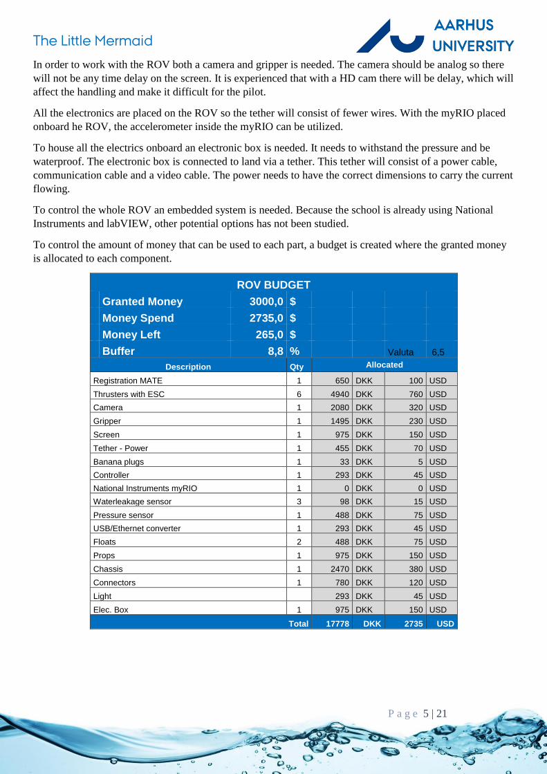
To control the amount of money that can be used to each part, a budget is created where the granted money
is allocated to each component.
ROV BUDGET
Granted Money 3000,0 $
Money Spend 2735,0 $
Money Left 265,0 $
Buffer 8,8 % Valuta 6,5
Description Qty Allocated
Registration MATE 1 650 DKK 100 USD
Thrusters with ESC 6 4940 DKK 760 USD
Camera 1 2080 DKK 320 USD
Gripper 1 1495 DKK 230 USD
Screen 1 975 DKK 150 USD
Tether - Power 1 455 DKK 70 USD
Banana plugs 1 33 DKK 5 USD
Controller 1 293 DKK 45 USD
National Instruments myRIO 1 0 DKK 0 USD
Waterleakage sensor 3 98 DKK 15 USD
Pressure sensor 1 488 DKK 75 USD
USB/Ethernet converter 1 293 DKK 45 USD
Floats 2 488 DKK 75 USD
Props 1 975 DKK 150 USD
Chassis 1 2470 DKK 380 USD
Connectors 1 780 DKK 120 USD
Light 293 DKK 45 USD
Elec. Box 1 975 DKK 150 USD
Total 17778 DKK 2735 USD

The Little Mermaid
P a g e 6 | 21
3 ROV design This chapter describes the design made on the ROV but also the selection of the components. There have
been many ideas for the design and it have been through many iterations.

The Little Mermaid
P a g e 7 | 21
3.1 General
The design is made of four plastic plates held together with M8 bolts. All the buoyancy material is placed on
top of the construction and some weight material at the bottom, in order to get a better stability. For the
simplicity of the design, the chassis is symmetric. This makes it easier to place the center of gravity in the
middle of the thrusters. In the process of the designing phase the center of buoyancy (CB) and the center of
gravity (CG) have been checked at all times, to make sure the placing of all the components is in harmony.
This is done with SolidWorks, a CAD program. The center of gravity can be calculated automatically with
SW, if all parts and components have the right mass and geometry. The same goes for the CB, but here the
whole construction is turned into water. Due to Archimedes law, the center of buoyancy must be in the
center of the water displaced by the ROV. The distance between the two points is 58mm.
3.2 Chassis
The chassis is made of HDPE, High-density polyethylene. The reason for choosing HDPE is that the density
is below the density of water, and therefore it will float slightly. Furthermore, the material can withstand
temperatures below 0˚C. Another possibility is PP since it has a stronger E-module than HDPE but this
material cannot resist minus degrees. Another crucial aspect when deciding what materials to use for
underwater robots is the materials ability not to absorb water. This will result in a change of the
constructions dimensions, which can have crucial consequences. In the case, HDPE is ideal and almost
complete resistant. The construction is designed so the water flow from the thrusters do not interfere with
each other.
CB
CG
The Little Mermaid
P a g e 8 | 21
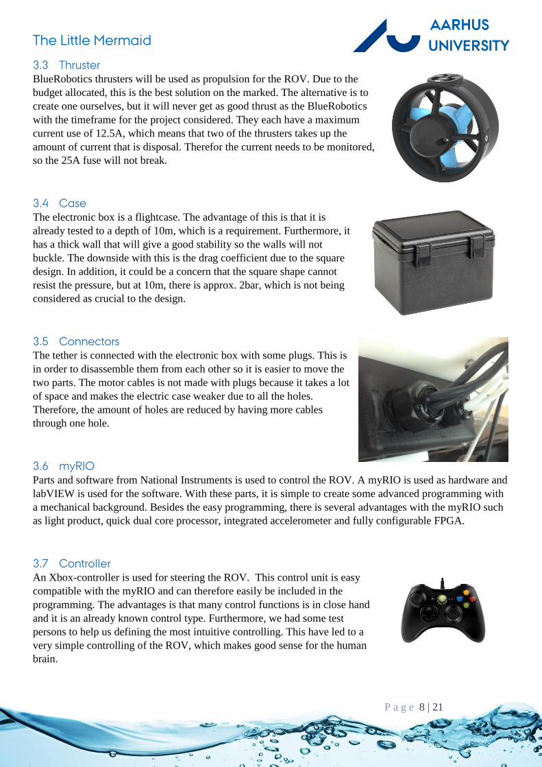
3.3 Thruster
BlueRobotics thrusters will be used as propulsion for the ROV. Due to the
budget allocated, this is the best solution on the marked. The alternative is to
create one ourselves, but it will never get as good thrust as the BlueRobotics
with the timeframe for the project considered. They each have a maximum
current use of 12.5A, which means that two of the thrusters takes up the
amount of current that is disposal. Therefor the current needs to be monitored,
so the 25A fuse will not break.
3.4 Case
The electronic box is a flightcase. The advantage of this is that it is
already tested to a depth of 10m, which is a requirement. Furthermore, it
has a thick wall that will give a good stability so the walls will not
buckle. The downside with this is the drag coefficient due to the square
design. In addition, it could be a concern that the square shape cannot
resist the pressure, but at 10m, there is approx. 2bar, which is not being
considered as crucial to the design.
3.5 Connectors
The tether is connected with the electronic box with some plugs. This is
in order to disassemble them from each other so it is easier to move the
two parts. The motor cables is not made with plugs because it takes a lot
of space and makes the electric case weaker due to all the holes.
Therefore, the amount of holes are reduced by having more cables
through one hole.
3.6 myRIO
Parts and software from National Instruments is used to control the ROV. A myRIO is used as hardware and
labVIEW is used for the software. With these parts, it is simple to create some advanced programming with
a mechanical background. Besides the easy programming, there is several advantages with the myRIO such
as light product, quick dual core processor, integrated accelerometer and fully configurable FPGA.
3.7 Controller
An Xbox-controller is used for steering the ROV. This control unit is easy
compatible with the myRIO and can therefore easily be included in the
programming. The advantages is that many control functions is in close hand
and it is an already known control type. Furthermore, we had some test
persons to help us defining the most intuitive controlling. This have led to a
very simple controlling of the ROV, which makes good sense for the human
brain.

The Little Mermaid
P a g e 9 | 21
3.8 Gripper
There was no gripper found that fulfilled the requirement. The gripper is therefore a 3D printed prototype.
The gripper will be developed after some testing with the prototype in order to get some experience. The
actuator for the gripper is a modified bilge pump. The propeller is dismounted so the rotor can be connected
together with the gripper. The advantage with a bilge pump is that it is already waterproof.
3.9 Float
Both the float for the ROV and the tether is made of a foam that are normally used for isolating pipes. The
foam material has a very low density (30-40kg/m3) and has a good immunity to absorbing water. This makes
it perfect for floating material. The amount of material depends on density of the ROV without the buoyancy
material. To get the most stable and efficient ROV, the total density should be just below 1kg/m3. Because
not all components are included in the CAD model, the construction will be heavier than calculated.
Therefore, it will be constructed as extra buoyant by making a safety margin.
desired density of ROV:
The ROV w/o float:
Mass of ROV w/o float:
Volume of ROV w/o float:
Density of ROV w/o float:
Calculation of the lenght of float:
Outer diameter of float:
Thickness of float:
Float density:
Cross-section float:
Length of float to make the total ROV density 0,90:
Lenght of float on both side:
denROV 1gm
cm3
100% 10%( ) 0.9gm
cm3
masso 20663.55gm
volo 19644cm3
densityo
masso
volo
1.052gm
cm3
dia 72mm
tyk 22mm
densityf 35kg
m3
Af
4dia
2dia 2 tyk( )
2 3.456 10
3 mm
2
Sfloat
masso Af S densityf
volo Af S denROV
solve S
float 2
simplify
6934.0 gm m
kg
5.9e6 cm3
m2
Sfloat
2517 mm

The Little Mermaid
P a g e 10 | 21
3.10 Weight adjustment
In order to adjust the weight point after the ROV have been launched, some weight blocks has been added at
the bottom of the ROV. These can slide forward and backwards to adjust the static pitch angle.
3.11 Tether
The tether consist of three cables.
Power Cable
Communication Cable
Video Cable
The power cable will supply the ROV with 12V from land. What is crucial here is the power loss in the
cable, which can have big influence on the performance. It is therefore a balance between a big power cable
and a big voltage drop. With a voltage drop too big, the ROV cannot dive. With a power cable too big, the
ROV will not be able to drag the cable. The calculation of minimum cross section of the wire is then:
The 4x4mm2 seems as the best solution, but the cable might be too heavy, so the 4x2.5mm2 is chosen
instead. The cable will be a H07-rubber cable, which is very flexible. This makes the ROV very
maneuverable. Due to a smaller cross-section.
Specific resistance for cobber
Length of tether
Possible cable sizes
Voltagedrop acording to cable size
q 0.0175 mm
2
m
L 2 18 m
I 25A Current
kvd
2 2.5
2 4
4 2.5
4 4
mm2
q L I 2
kvd
6.3
3.938
3.15
1.969
V

The Little Mermaid
P a g e 11 | 21
The communication cable is a cat6-ethernet cable. This cable has twisted wire so the interference from the
power cable is minimized.
The video cable is a pre-attached cable that is already mounted on the camera.
3.12 Tilt
Because there is no automate adjusting of the CG after the grippe has grabbed something, it needs to be
insured that the ROV can still lift.
Calculate the moment around CB:
∑𝑀𝐶𝐵 = 𝐶𝐺 ∗ sin(𝜃) ∗ 𝐵𝐺 − 𝐹𝐺 ∗ cos(𝜃) ∗ 𝐷 = 0 →
𝐶𝐺 ∗ sin(𝜃) ∗ 𝐵𝐺 = 𝐹𝐺 ∗ cos(𝜃) ∗ 𝐷 →
sin(𝜃)
cos(𝜃)=
𝐹𝐺 ∗ 𝐷
𝐶𝐺 ∗ 𝐵𝐺→
tan(𝜃) =𝐹𝐺 ∗ 𝐷
𝐶𝐺 ∗ 𝐵𝐺→
𝜃 = arctan (𝐹𝐺 ∗ 𝐷
𝐶𝐺 ∗ 𝐵𝐺)
Data is obtained from SolidWorks:
By expressing the angle as a function of force acting on the gripper:
f FG atanFG D
mrov g BG
mrov 21kg D 450mm BG 58mm

The Little Mermaid
P a g e 12 | 21
The maximum angle for the ROV with the maximum force of 20N acting on the gripper:
When the thrusters are angled, it is not 100% power that is used for lifting, but only component of the max
thrust. Therefore, it needs to be checked whether the ROV has enough thrust for lifting.
It is assumed that the density of the ROV is 1kg/m3 and can therefore be neglected. Therefore, the thrusters
only need to overcome the force acting on the gripper, which is the 20N. The thruster have a strong side and
a weak side, meaning it is not producing the same amount of thrust both forward and backwards.
𝐹𝑔𝑜𝑜𝑑 = 2 ∗ 23𝑁 ∗ cos(deg 37) = 36.7𝑁
36.7𝑁 > 20𝑁 → 𝑜𝑘
𝐹𝑏𝑎𝑑 = 2 ∗ 18𝑁 ∗ cos(deg 37) = 28.8𝑁
28.8𝑁 > 20𝑁 → 𝑜𝑘
The ROV can lift the object both with the strong and weak side of the thrusters.
4 CFD With the ROV fully submerged in water, it would be logical to look at the flow around the structure. During
the design face, the ROV had been designed with many openings in the structure to let water flow freely.
Especially forward, a low drag coefficient was wanted. To check whether this was complied, a flow analysis
was set up. For that, a speed was need. From earlier tests in pools, we had estimated the top speed of the
ROV to about 0.8m/s. This speed was used in the analysis.
Usually in such work, the drag coefficient is the wanted result, but this number can only be used if you have
something to compare it with. For example in the car industry, this makes sense. It is easy to compare two
cars side by side, based on the drag coefficient. However, it does not make sense to compare a ROV to a car.
0 5 10 15 200
10
20
30
40
f FG deg
FG
f 20N( ) 37 deg

The Little Mermaid
P a g e 13 | 21
Instead, we looked at force needed to reach 0.8m/s in three directions. Forward, sideways and downwards.
This is the results:
Forward Sideways Downward
Speed 0.8m/s 0.8m/s 0.8m/s
FD 39N 76.N 96N
Forward 39N of thrust is required to reach 0.8m/s. The two thruster are capable of delivering 46N of thrust,
which make our estimated top speed plausible. Sideways the needed thrust is close to the double.
Downwards we see the worst results. This is easier to understand by looking at the visualization of the drag.
The blue zones is the result of higher drag.
This is a section view to show the drag of the forward motion.
Here are the section views for sideways and downward motion.
What can be interpreted from this? The ROV has the least amount of drag in the forward motion, just as it
was wanted. The sideway and down drags are much bigger, but the sideways drag does not make that a big

The Little Mermaid
P a g e 14 | 21
deal. Since sideways motion are most of the time used for small precise maneuvers, so speed is not a key
factor. However, the ROV could gain from minimizing the drag for the up and down motion. Another
important interpretation is that the electric box is creating most of the drag. Just by rethinking this box, the
drag will be rectified a lot.
5 Electric The surface system consist of a computer, video monitors and an Xbox 360 controller. The onboard analog
cameras on the ROV is hooked up directly to the video monitors. The Xbox 360 controller is connected to
the computer by USB.
The tether consist of different types of cable, a power cable, analog video cable and an Ethernet cable.
Normally a myRIO is connected to a computer with a USB cable or through Wi-Fi. Since USB cables are
limited by their length and wireless connections does not work underwater, another solution had to be found.
The myRIO runs a Linux based OS that supports ASIX chipsets. This means an USB/Ethernet adapter based
on that chipset would work. Now it is possible to use Ethernet as data exchange between the myRIO and the
surface computer.
The ROV system is based on the myRIO. It is an embedded system with 10 analog inputs, 6 analog outputs,
40 digital I/O lines and a built-in accelerometer. All sensors, current-, depth- and water leakage sensor are
connected to the myRIO, it then processes the signal and sends it to the surface computer.
The thrusters are controlled by a standard ESC(Electronic Speed Control), which only need a PWM(Pulse-
Width modulation) signal from the myRIO. This mixed with the Xbox 360 controller gives fully step less
control over the thrusters.
The actuator on the gripper, is a stripped down bilge pump, which is a DC motor. To control this an H-
bridge is designed and built.
The current sensor is used to keep the ROV’s current consumption under 25A. Since it is capable of using
above 25A, the sensor is used as feedback in the software to adjust the PWM signal. This way the current
consumption is limited.

The Little Mermaid
P a g e 15 | 21
6 Software The software is running on both the myRIO and the computer. Nearly all the processing is done on the
computer to spare the processor on the myRIO, since the computer is much faster. After the program has
been started, it initialize the Xbox 360 controller, the sensor and the IO.
On the computer, the steering algorithms is applied on the input data from the Xbox 360 controller. The data
is then send to the ROV. The same data is also displayed on the GUI(Graphic User Interface), to help
maneuver the ROV. At the same time, the computer is also receiving the sensor data from the ROV. The
computer process the data, and display the necessary data on the GUI.

The Little Mermaid
P a g e 16 | 21
Onboard the ROV, the myRIO receives data from the computer. This data is used to control the thrusters and
grippers by PWM signals. If the current consumption gets near the limit of 25A, the PWM is adjusted to
make sure the current consumption stays below 25A. The myRIO is also passing on data from the sensor to
the computer.
7 Project management From the start of the project, we made a time schedule to keep track of tasks and time. The time schedule
was updated at least once every week to maintain its effect. This way it was used to keep focus on a single
task, even if the project seemed big and unmanageable. It can also be used to see the bigger picture. Are we
behind or ahead of schedule, and what are the upcoming deadlines and tasks? With these two properties, the
time schedule helps maintaining a good workflow throughout the whole project.
On a daily basis, project management is executed more like scrum. There will be held a 15-minute meeting
every morning. At this meeting, every team member goes through three highlights:
What did I do since yesterday to help achieve the team’s goal(s)?
What are the goal(s) for today, and how can I help achieve them?
Do I see any problems in relation to the goal(s)?
Since it is on daily basis, these goals are small, and smaller goals are easier to cope with, which helps
keeping focus. It also makes sure that everybody knows what the others are doing, so two people do not end
up solving the same task. A team member might have a solution to what another might perceive as a
problem.
On every subtask, responsibility was assigned to a person. This does not mean the person has to complete
the task himself, but he has the responsibility for the task being done in time.

The Little Mermaid
P a g e 17 | 21

The Little Mermaid
8 Safety
8.1 Risk Analysis
A risk analysis has been developed in order to detect the highest hazards. Those risks or hazards that have a
high potential will be prevented with a plan how to eliminate them.
Risk Analysis No. Potential Risk Risk consequences Seriousness Probability How to provent the risk
1 Finger inside the propeller
Hard hit on the finger 4 3 Take power of the ROV during launch and when taking it up from the water
2 Electric chock in the electronic box
Minor consequences because of the 12V, but can give a chock if the hands are wet
1 4 Turn off the power before entering the electronic box
3 Jammed hand in gripper
Scratches on the hand 2 1 Turn off the power when working on the ROV
4 Heavy lifting - When lifting the ROV alone
Back problems due to heavy lifting and upractical shape.
2 4 Two persons should lift the ROV
5 Cutting on the sharp edges
Scratch on arm and hands
4 3 Protect all sharp edges
6 ROV falls down on a foot
Hard hit on the foot, scrathes on leg and foot, blue marks
3 3 Never place the ROV on small tables also with low friction surface
7 Fuse will break All power shuts down 2 5 Measure the current a give a feedback to the output.
8 Water leak in the elektric case
The electronic will break
4 4 Often check for water leak - Install a water sensor inside the case, that alarm when water is detected.
9 Tether plugs disconnecs
The communication and power will be lost to the ROV
2 5 Secure the plugs so they will not disconnect
Action
No.2 Dry your hands before working with the electronics and turn of the power.
No.4 At least two persons should lift the ROV.
No.5 Remove or protect all sharp edges.
No.7 Install a current sensor that gives feedback to the electronic system in order to prevent the fuse
from blowing.
No.8 Install water sensors inside the case, and frequently inspect the case.
No.9 Install some unions to secure the plugs on the ROV.
8.2 FMEA
A FMEA have been developed to lay out the failure that might occur.
Here the different failures are evaluated with three different characters.
Severity How big is the consequences if this failure is occurring?
Probability How often and likely is the failure to occur?
Detection How easy is the failure to detect and how long does the failure take to fix?

The Little Mermaid
P a g e 19 | 21
9 Cost monitoring Due to a tight budget, the money has at all times been monitored according to the budget made. The
following diagram was used for monitoring:

The Little Mermaid
P a g e 20 | 21
In this list the price of the parts sponsored are not included, because the price of some of the parts are
unknown:
Video cable
Camera
Communication cable
myRIO
10 Challenges
10.1 Technical
The FOV(Field of View) is unknown for our underwater cameras, which means it cannot be calculated
where to place them, to get the wanted view. We also know cameras decrease in FOV when they are
submerged, but not by how much. Therefore, it was difficult to predict a good mounting position. The
solution was to mount the cameras above water while the live video feed was running. Then we would
submerge the whole ROV, and look at the decreased FOV in water. We then knew where the camera should
be relocated, making it an iterative process.
To save time we were looking for a complete gripper online. The professional grippers were too expensive,
and the “just for fun” grippers were not build for underwater use. We estimated that some of the designs
could be used under water, if the actuators were replaced. We could not find any actuators that was
submergible, so this could not be done. Therefore, we ended up designing our own gripper with inspiration
from the design we had been looking at. We designed the gripper so we could use a rotating actuator, this
way we could use a bilge pump as actuator.
10.2 Non-technical
Time has been our biggest challenge throughout the project. From when we started the project in February
and until the hand-in of the video was due in the beginning of May, we only had 3 months. 3 months for a
small team to build a ROV from scratch, is not much. Especially since none from the team had any
experience within this area of expertise. The way we did overcome this, was to evaluate the assignment from
start. This way we found the key features and key components, which meant we could spend our time on the
most important tasks. Time planning/time schedule was an important element in this process. The tight
timeframe short time also meant we only had time to produce one prototype, and we did not have time for
bigger changes or problems. Therefore, we made our design process long, so our choices could be well
thought out. When we then started the process of building, every hole, wire and bracket did line up, because
of our in-depth design process. This way only the software needed minor adjustments.
11 Lessons learned
11.1 Subcontractor and delivery time
One of the most repeated problems is subcontractors and delivery time. At first when we found the perfect
power cable for out tether, we thought we had found the ideal solution. Later it turned out the delivery time
was 8 weeks, and therefore the cable was not an option, since we would not receive it in time for the
demonstration video to be made. Other subcontractors did not meet the agreed deadlines. These experiences
may come from that the subcontractors do not have the same commitment to the project as we do.
11.2 Interpersonal
With a project like this it is preferred to have a company or two who supports you. It can be financially, with
giveaways or by offering technical support. In the beginning, we contacted companies who we thought
would have an interest in helping us. To start with, we received many rejections, but for every time we were

The Little Mermaid
P a g e 21 | 21
to present our project, we got better. We learned a lot about how to contact a company in a professional
manner, and what you should do to have the best chance of success. We also learned to deal with these
rejections, and that a rejection should not affect the mood.
12 Teamwork With a team consisting of only three members, it is possible to use a very flat organizational structure. We
have been working very close together on all tasks, but the responsibilities have been distributed. Dennik
was in charge of the structural design, Poul was in charge of software and electronics and Jens has been our
handyman. Such a small team have both some pros and cons. When decisions have to be made, it is much
easier to make them in a small team compared to a large team. It larger teams, people tends to learn back
and work less because they do not feel the same amount of responsibility. This have not been an issue for us
because of the small group and the deadlines being a constant pressure.
13 Future improvements Since the first prototype has been developed and built in just three months, almost every part could be
optimized or improved. Some parts needs to be improved more than others do, and the most distinctive
improvements are:
The gripper could be optimized or maybe the complete gripper design should be rethought. It should be
possible to find a better actuator than a bilge pump. The bilge pump do not always run smoothly, especially
with low rpm. The design should be more rigid, and another manufacturing process should be found. The
3D-printer material is not optimal. Generally, more tools for specific missions should be developed and
manufactured.
Vision is crucial to complete a task underwater. Therefore, more cameras should be mounted, and their FOV
should be well considered. More viewing angels will help to counteract the missing depth perception.
The accelerometer in the myRIO should be used to program a self-stabilizing module. This way the ROV
will be less prone to currents and gravity point changes, as when the ROV lifts a heavy object. In relation to
water depth, our only weak spot it the rectangular electric box. If this box is replaced with a cylindrical one,
our ROV could go must deeper. This would actually make it much more useable in the ocean.
14 Reflections A large part of this project has been about electrical and software. Topics that is not part of our professional
qualifications as mechanical engineers. To complete the ROV we had to get to know these subjects. Here we
learned and experienced that an engineer’s value is not only his knowledge, but just as much his ability to
acquire new knowledge about a topic. This is a core quality of engineering, which should not be taken for
granted.
15 References Underwater Robotics Sience, Design and Fabrication
2010 - Steve W. Moore, Harry Bohm, Vickie Jensen
The ROV Manual, Second Edition, 2007
Robert D. Christ, Robert L. Wernli, Sr.
http://www.marinetech.org/rov-competition/

ROV system
DC 12 V
25 A
Surface system
Tether
Gripper PCB
Xbox 360 Controller
Computer
Monitor
Motor ESC
Thrusters
Gripper
Camera
Water leakage sensor
NI myRIO
Current sensor Depth sensor
12 V
12 V
GND
Ethernet
Composite video
The Little Mermaid