The Lightwave 3D Beginners Guide - UCLMedii.uclm.es › ~jmlova › Archivos › GE › Archivos ›...
30
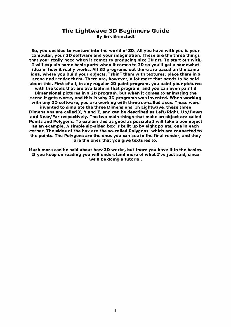
1 The Lightwave 3D Beginners Guide By Erik Brimstedt So, you decided to venture into the world of 3D. All you have with you is your computer, your 3D software and your imagination. These are the three things that your really need when it comes to producing nice 3D art. To start out with, I will explain some basic parts when it comes to 3D so you’ll get a somewhat idea of how it really works. All 3D programs out there are based on the same idea, where you build your objects, “skin” them with textures, place them in a scene and render them. There are, however, a lot more that needs to be said about this. First of all, in any regular 2D paint program, you paint your pictures with the tools that are available in that program, and you can even paint 3 Dimensional pictures in a 2D program, but when it comes to animating the scene it gets worse, and this is why 3D programs was invented. When working with any 3D software, you are working with three so-called axes. These were invented to simulate the three Dimensions. In Lightwave, these three Dimensions are called X, Y and Z, and can be described as Left/Right, Up/Down and Near/Far respectively. The two main things that make an object are called Points and Polygons. To explain this as good as possible I will take a box object as an example. A simple six-sided box is built up by eight points, one in each corner. The sides of the box are the so-called Polygons, which are connected to the points. The Polygons are the ones you can see in the final render, and they are the ones that you give textures to. Much more can be said about how 3D works, but there you have it in the basics. If you keep on reading you will understand more of what I’ve just said, since we’ll be doing a tutorial.
Transcript of The Lightwave 3D Beginners Guide - UCLMedii.uclm.es › ~jmlova › Archivos › GE › Archivos ›...
1
The Lightwave 3D Beginners Guide By Erik Brimstedt
So, you decided to venture into the world of 3D. All you have with you is your computer, your 3D software and your imagination. These are the three things
that your really need when it comes to producing nice 3D art. To start out with, I will explain some basic parts when it comes to 3D so you’ll get a somewhat idea of how it really works. All 3D programs out there are based on the same
idea, where you build your objects, “skin” them with textures, place them in a scene and render them. There are, however, a lot more that needs to be said
about this. First of all, in any regular 2D paint program, you paint your pictures with the tools that are available in that program, and you can even paint 3 Dimensional pictures in a 2D program, but when it comes to animating the
scene it gets worse, and this is why 3D programs was invented. When working with any 3D software, you are working with three so-called axes. These were
invented to simulate the three Dimensions. In Lightwave, these three Dimensions are called X, Y and Z, and can be described as Left/Right, Up/Down and Near/Far respectively. The two main things that make an object are called Points and Polygons. To explain this as good as possible I will take a box object
as an example. A simple six-sided box is built up by eight points, one in each corner. The sides of the box are the so-called Polygons, which are connected to the points. The Polygons are the ones you can see in the final render, and they
are the ones that you give textures to.
Much more can be said about how 3D works, but there you have it in the basics. If you keep on reading you will understand more of what I’ve just said, since
we’ll be doing a tutorial.
2
The Main Programs
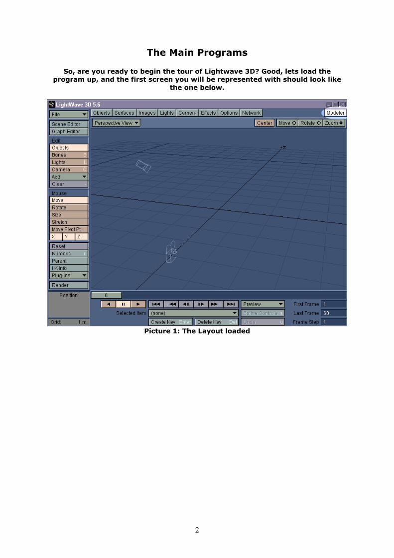
So, are you ready to begin the tour of Lightwave 3D? Good, lets load the program up, and the first screen you will be represented with should look like
the one below.
Picture 1: The Layout loaded

3
This is the Layout, and this is where you load objects you have created, give them textures, add lights, animate and render etc. There is one more part of Lightwave, and it is called Modeler. In the top right corner you should see a
button named “Modeler”, click that one and the Modeler should load up, looking something like this:
Picture 2: The Modeler loaded
4
Getting to know Modeler
I will start with Modeler, go through all the basics and then move over to Layout. You are now represented with four views. The Top left is called “Top View” and this is where you see your object from above. The bottom left is
called “Face View” or “Front View” and this is where you see your object from the front. The bottom right is called “Side View” and this is where you see your object from the side, from the left actually. The Top right is called “Perspective
View” and you can change the view of the object as you please here.
Push the “d” key on the keyboard and an options panel will come up. This panel let’s you set the very basics of the Modeler. If it isn’t already set, change the Preview Type to “Open GL Smooth Shaded” and Unit System to “SI”. In the Visibility section, checkmark all the boxes but “Patch Polygon” and click OK.
To get full control over Modeler, I will give you an explanation over all the things you see. All three views Top, Left and Front are built up by so called
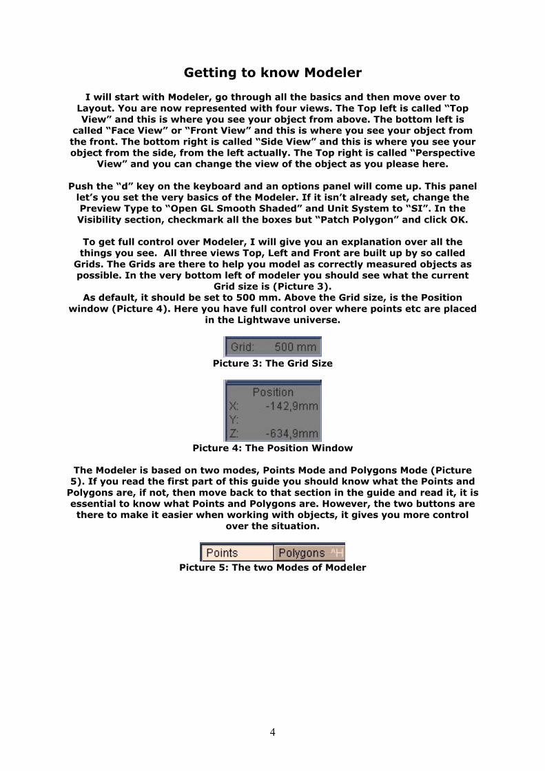
Grids. The Grids are there to help you model as correctly measured objects as possible. In the very bottom left of modeler you should see what the current
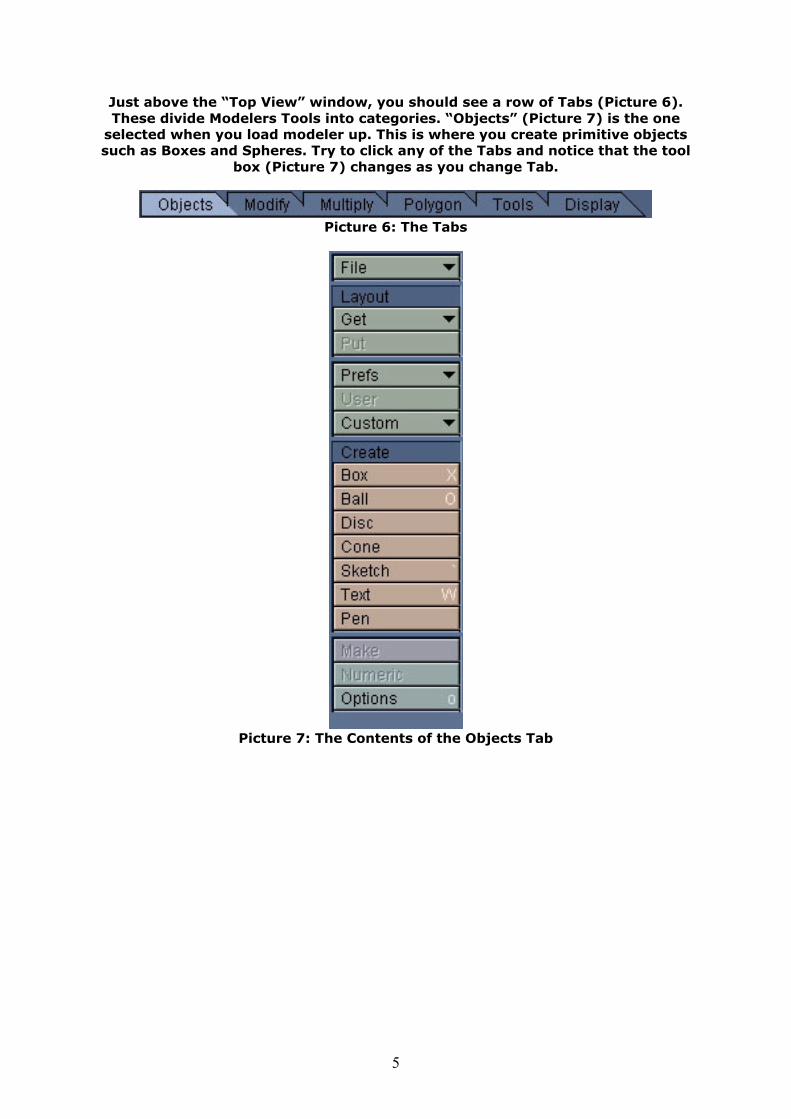
Grid size is (Picture 3). As default, it should be set to 500 mm. Above the Grid size, is the Position
window (Picture 4). Here you have full control over where points etc are placed in the Lightwave universe.
Picture 3: The Grid Size
Picture 4: The Position Window
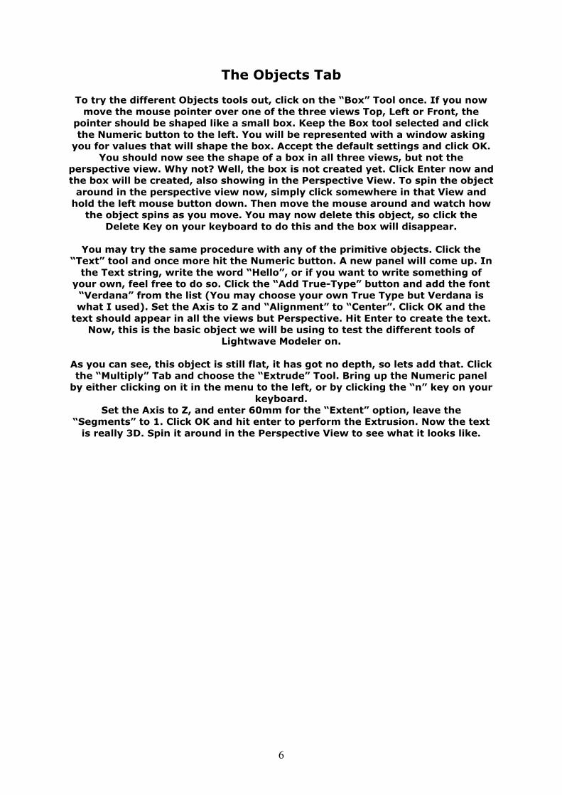
The Modeler is based on two modes, Points Mode and Polygons Mode (Picture
5). If you read the first part of this guide you should know what the Points and Polygons are, if not, then move back to that section in the guide and read it, it is essential to know what Points and Polygons are. However, the two buttons are there to make it easier when working with objects, it gives you more control
over the situation.
Picture 5: The two Modes of Modeler
5
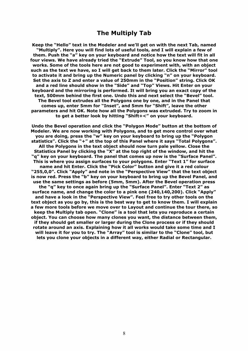
Just above the “Top View” window, you should see a row of Tabs (Picture 6). These divide Modelers Tools into categories. “Objects” (Picture 7) is the one
selected when you load modeler up. This is where you create primitive objects such as Boxes and Spheres. Try to click any of the Tabs and notice that the tool
box (Picture 7) changes as you change Tab.
Picture 6: The Tabs
Picture 7: The Contents of the Objects Tab
6
The Objects Tab
To try the different Objects tools out, click on the “Box” Tool once. If you now move the mouse pointer over one of the three views Top, Left or Front, the
pointer should be shaped like a small box. Keep the Box tool selected and click the Numeric button to the left. You will be represented with a window asking
you for values that will shape the box. Accept the default settings and click OK. You should now see the shape of a box in all three views, but not the
perspective view. Why not? Well, the box is not created yet. Click Enter now and the box will be created, also showing in the Perspective View. To spin the object
around in the perspective view now, simply click somewhere in that View and hold the left mouse button down. Then move the mouse around and watch how
the object spins as you move. You may now delete this object, so click the Delete Key on your keyboard to do this and the box will disappear.
You may try the same procedure with any of the primitive objects. Click the
“Text” tool and once more hit the Numeric button. A new panel will come up. In the Text string, write the word “Hello”, or if you want to write something of
your own, feel free to do so. Click the “Add True-Type” button and add the font “Verdana” from the list (You may choose your own True Type but Verdana is what I used). Set the Axis to Z and “Alignment” to “Center”. Click OK and the
text should appear in all the views but Perspective. Hit Enter to create the text. Now, this is the basic object we will be using to test the different tools of
Lightwave Modeler on.
As you can see, this object is still flat, it has got no depth, so lets add that. Click the “Multiply” Tab and choose the “Extrude” Tool. Bring up the Numeric panel
by either clicking on it in the menu to the left, or by clicking the “n” key on your keyboard.
Set the Axis to Z, and enter 60mm for the “Extent” option, leave the “Segments” to 1. Click OK and hit enter to perform the Extrusion. Now the text
is really 3D. Spin it around in the Perspective View to see what it looks like.

7
The Modify Tab Enter the Modify Tab. Now we are going to try out a few of the tools here. Let’s start with the “Move” tool. Click it once to activate it, and then move the mouse
pointer to any of the three views Top, Left or Front and click the left mouse button. Hold it down and move the mouse around, watch how the object moves. If you release the mouse button now, the new position will be remembered. If
you were not satisfied with the movement then simply click the “u” key on your keyboard to undo the last procedure. The amount of Undo levels are set in the
options panel under the Objects Tab, so lets bring it up. Simply click the “o” key on your keyboard. I’m not going to dig deep into what the different settings are
that you can set here, but in the bottom of the panel, you should see the amount of Undo levels. Default should be set to 15, which is a good number. If
you want to change it, then simply do so by entering a new number and by clicking OK.
Lets move back to the Modify Tab, so we can try out a few more of those tools.
Next on the list is “Rotate”. Click it once to activate it, and move the mouse pointer in any of the three views. How you rotate the object, depends on in
which of the three views you do it in. If you want to rotate the text around the Y axis, you would be doing it in the Top View. If you want to rotate the text
around the Z axis, you would be doing it in the Front View, and if you want to rotate around the X axis, you would be doing this in the Left View. For now, we will just use the rotate tool with the numeric panel so lets bring it up by clicking
“n” key. Set the axis to Y and enter an amount of 45 degrees in the “Angle” string. Leave the Center options at 0 on each axis. Click OK and the rotation is
performed.
Click “u” to Undo the last procedure, and let’s move on to the next tool. The Size and Stretch tools are almost the same. The Size tool lets you change the size of your object on all three axes while the stretch tool can change the size on just
one or two axes. Feel free to try the tools out. The Drag Tool was made for moving points that are in an object. Click to activate it, then press the mouse button when you are over a point and drag it for just a test. Click “u” to undo.
Remember that you can always use the Numeric Panel to give more exact values of your operations. Those were the basic Modify tools and I will leave the
rest for you to try.
8
The Multiply Tab Keep the “Hello” text in the Modeler and we’ll get on with the next Tab, named
“Multiply”. Here you will find lots of useful tools, and I will explain a few of them. Push the “a” key on your keyboard and notice how the text will fit in all
four views. We have already tried the “Extrude” Tool, so you know how that one works. Some of the tools here are not good to experiment with, with an object
such as the text we have, so I will get back to them later. Click the “Mirror” tool to activate it and bring up the Numeric panel by clicking “n” on your keyboard. Set the axis to Z and enter a value of 250mm in the “Position” string. Click OK and a red line should show in the “Side” and “Top” Views. Hit Enter on your
keyboard and the mirroring is performed. It will bring you an exact copy of the text, 500mm behind the first one. Undo this and next select the “Bevel” tool.
The Bevel tool extrudes all the Polygons one by one, and in the Panel that comes up, enter 5mm for “Inset”, and 5mm for “Shift”, leave the other
parameters and hit OK. Note how all the Polygons was extruded. Try to zoom in to get a better look by hitting “Shift+<” on your keyboard.
Undo the Bevel operation and click the “Polygon Mode” button at the bottom of Modeler. We are now working with Polygons, and to get more control over what
you are doing, press the “w” key on your keyboard to bring up the “Polygon statistics”. Click the “+” at the top of this Panel where it says “Total Polygons”.
All the Polygons in the text object should now turn pale yellow. Close the Statistics Panel by clicking the “X” at the top right of the window, and hit the
“q” key on your keyboard. The panel that comes up now is the “Surface Panel”. This is where you assign surfaces to your polygons. Enter “Text 1” for surface
name and hit Enter. Click the “Pick Color” button and give it a red colour “255,0,0”. Click “Apply” and note in the “Perspective View” that the text object is now red. Press the “b” key on your keyboard to bring up the Bevel Panel, and use the same settings as before (5mm, 5mm). After the Bevel operation press
the “q” key to once again bring up the “Surface Panel”. Enter “Text 2” as surface name, and change the color to a pink one (240,140,200). Click “Apply”
and have a look in the “Perspective View”. Feel free to try other tools on the text object as you go by, this is the best way to get to know them. I will explain a few more tools before we move over to Layout and continue the tour there, so
keep the Multiply tab open. “Clone” is a tool that lets you reproduce a certain object. You can choose how many clones you want, the distance between them,
if they should get smaller or larger during the Clone process or if they should rotate around an axis. Explaining how it all works would take some time and I will leave it for you to try. The “Array” tool is similar to the “Clone” tool, but lets you clone your objects in a different way, either Radial or Rectangular.
9
A Simple Tutorial
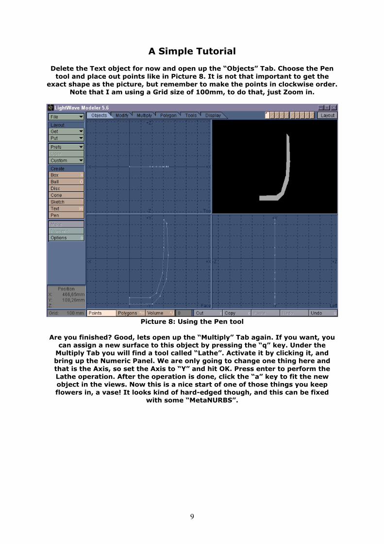
Delete the Text object for now and open up the “Objects” Tab. Choose the Pen tool and place out points like in Picture 8. It is not that important to get the
exact shape as the picture, but remember to make the points in clockwise order. Note that I am using a Grid size of 100mm, to do that, just Zoom in.
Picture 8: Using the Pen tool
Are you finished? Good, lets open up the “Multiply” Tab again. If you want, you
can assign a new surface to this object by pressing the “q” key. Under the Multiply Tab you will find a tool called “Lathe”. Activate it by clicking it, and bring up the Numeric Panel. We are only going to change one thing here and that is the Axis, so set the Axis to “Y” and hit OK. Press enter to perform the Lathe operation. After the operation is done, click the “a” key to fit the new object in the views. Now this is a nice start of one of those things you keep flowers in, a vase! It looks kind of hard-edged though, and this can be fixed
with some “MetaNURBS”.
10
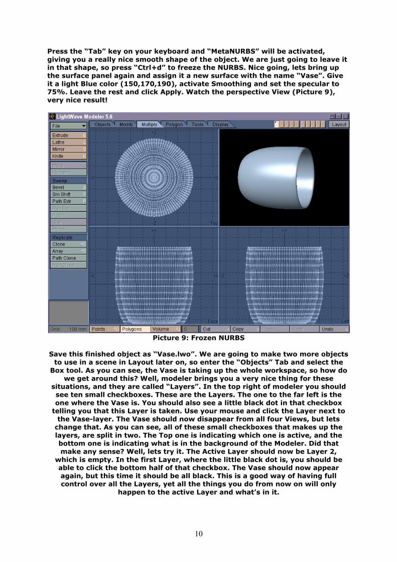
Press the “Tab” key on your keyboard and “MetaNURBS” will be activated, giving you a really nice smooth shape of the object. We are just going to leave it in that shape, so press “Ctrl+d” to freeze the NURBS. Nice going, lets bring up the surface panel again and assign it a new surface with the name “Vase”. Give it a light Blue color (150,170,190), activate Smoothing and set the specular to 75%. Leave the rest and click Apply. Watch the perspective View (Picture 9), very nice result!
Picture 9: Frozen NURBS
Save this finished object as “Vase.lwo”. We are going to make two more objects
to use in a scene in Layout later on, so enter the “Objects” Tab and select the Box tool. As you can see, the Vase is taking up the whole workspace, so how do
we get around this? Well, modeler brings you a very nice thing for these situations, and they are called “Layers”. In the top right of modeler you should see ten small checkboxes. These are the Layers. The one to the far left is the one where the Vase is. You should also see a little black dot in that checkbox
telling you that this Layer is taken. Use your mouse and click the Layer next to the Vase-layer. The Vase should now disappear from all four Views, but lets
change that. As you can see, all of these small checkboxes that makes up the layers, are split in two. The Top one is indicating which one is active, and the bottom one is indicating what is in the background of the Modeler. Did that make any sense? Well, lets try it. The Active Layer should now be Layer 2,
which is empty. In the first Layer, where the little black dot is, you should be able to click the bottom half of that checkbox. The Vase should now appear again, but this time it should be all black. This is a good way of having full control over all the Layers, yet all the things you do from now on will only
happen to the active Layer and what’s in it.
11
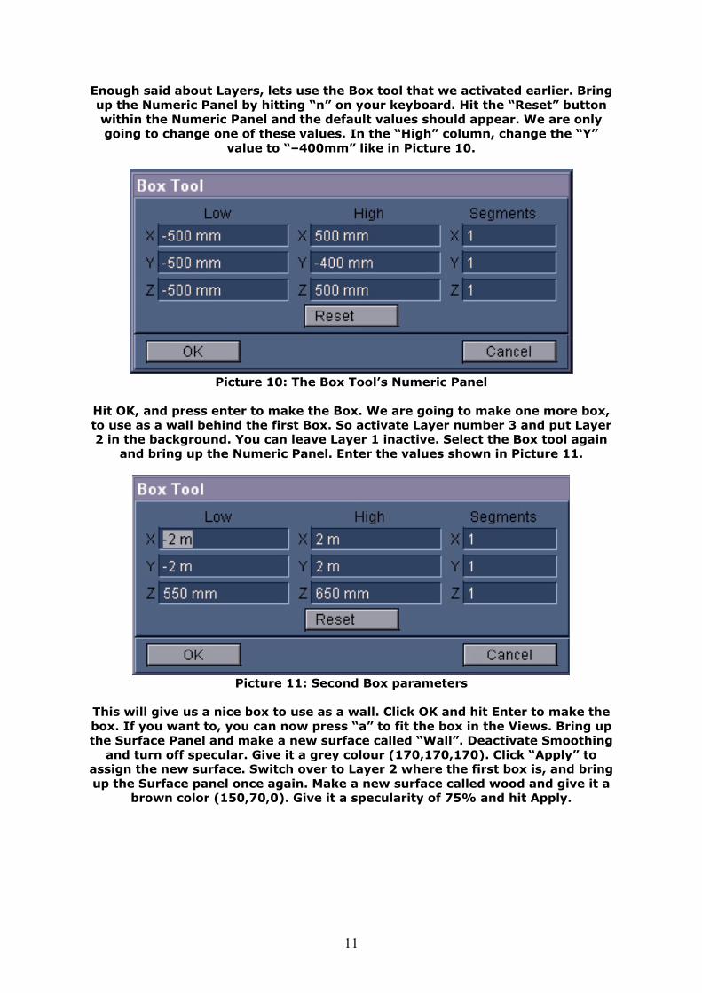
Enough said about Layers, lets use the Box tool that we activated earlier. Bring up the Numeric Panel by hitting “n” on your keyboard. Hit the “Reset” button within the Numeric Panel and the default values should appear. We are only going to change one of these values. In the “High” column, change the “Y”
value to “–400mm” like in Picture 10.
Picture 10: The Box Tool’s Numeric Panel
Hit OK, and press enter to make the Box. We are going to make one more box, to use as a wall behind the first Box. So activate Layer number 3 and put Layer 2 in the background. You can leave Layer 1 inactive. Select the Box tool again
and bring up the Numeric Panel. Enter the values shown in Picture 11.
Picture 11: Second Box parameters
This will give us a nice box to use as a wall. Click OK and hit Enter to make the box. If you want to, you can now press “a” to fit the box in the Views. Bring up the Surface Panel and make a new surface called “Wall”. Deactivate Smoothing
and turn off specular. Give it a grey colour (170,170,170). Click “Apply” to assign the new surface. Switch over to Layer 2 where the first box is, and bring up the Surface panel once again. Make a new surface called wood and give it a
brown color (150,70,0). Give it a specularity of 75% and hit Apply.
12
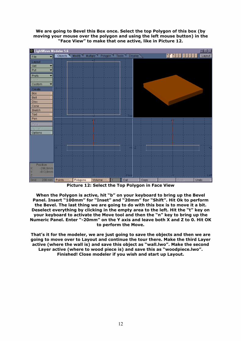
We are going to Bevel this Box once. Select the top Polygon of this box (by moving your mouse over the polygon and using the left mouse button) in the
“Face View” to make that one active, like in Picture 12.
Picture 12: Select the Top Polygon in Face View
When the Polygon is active, hit “b” on your keyboard to bring up the Bevel
Panel. Insert “100mm” for “Inset” and “20mm” for “Shift”. Hit Ok to perform the Bevel. The last thing we are going to do with this box is to move it a bit.
Deselect everything by clicking in the empty area to the left. Hit the “t” key on your keyboard to activate the Move tool and then the “n” key to bring up the
Numeric Panel. Enter “-20mm” on the Y axis and leave both X and Z to 0. Hit OK to perform the Move.
That’s it for the modeler, we are just going to save the objects and then we are going to move over to Layout and continue the tour there. Make the third Layer active (where the wall is) and save this object as “wall.lwo”. Make the second
Layer active (where to wood piece is) and save this as “woodpiece.lwo”. Finished! Close modeler if you wish and start up Layout.
13
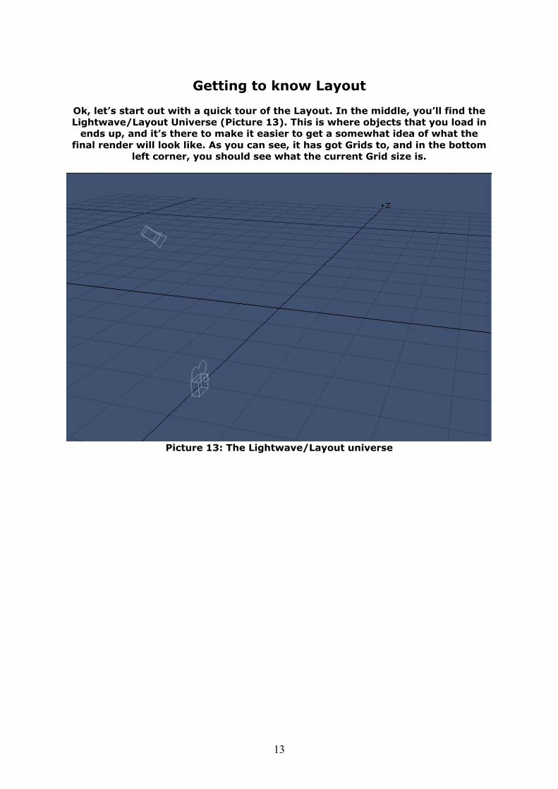
Getting to know Layout
Ok, let’s start out with a quick tour of the Layout. In the middle, you’ll find the Lightwave/Layout Universe (Picture 13). This is where objects that you load in
ends up, and it’s there to make it easier to get a somewhat idea of what the final render will look like. As you can see, it has got Grids to, and in the bottom
left corner, you should see what the current Grid size is.
Picture 13: The Lightwave/Layout universe
14
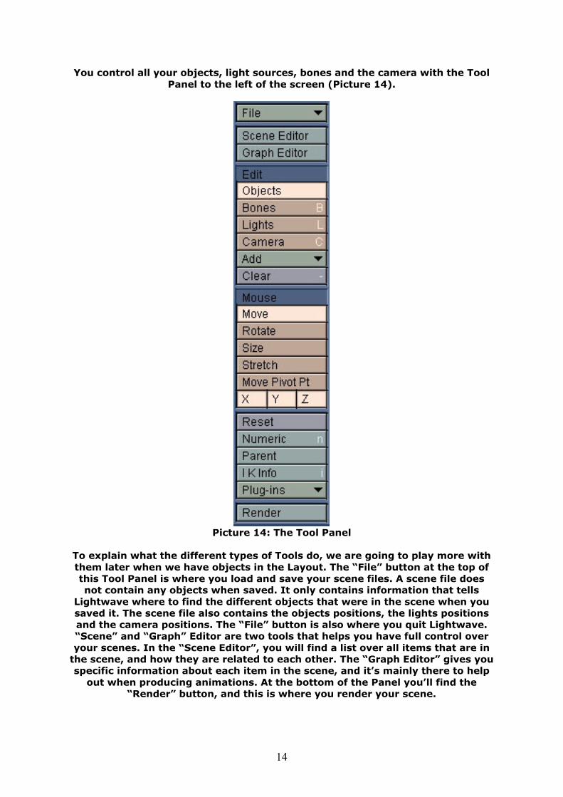
You control all your objects, light sources, bones and the camera with the Tool Panel to the left of the screen (Picture 14).
Picture 14: The Tool Panel
To explain what the different types of Tools do, we are going to play more with them later when we have objects in the Layout. The “File” button at the top of this Tool Panel is where you load and save your scene files. A scene file does not contain any objects when saved. It only contains information that tells
Lightwave where to find the different objects that were in the scene when you saved it. The scene file also contains the objects positions, the lights positions and the camera positions. The “File” button is also where you quit Lightwave. “Scene” and “Graph” Editor are two tools that helps you have full control over your scenes. In the “Scene Editor”, you will find a list over all items that are in
the scene, and how they are related to each other. The “Graph Editor” gives you specific information about each item in the scene, and it’s mainly there to help
out when producing animations. At the bottom of the Panel you’ll find the “Render” button, and this is where you render your scene.
15
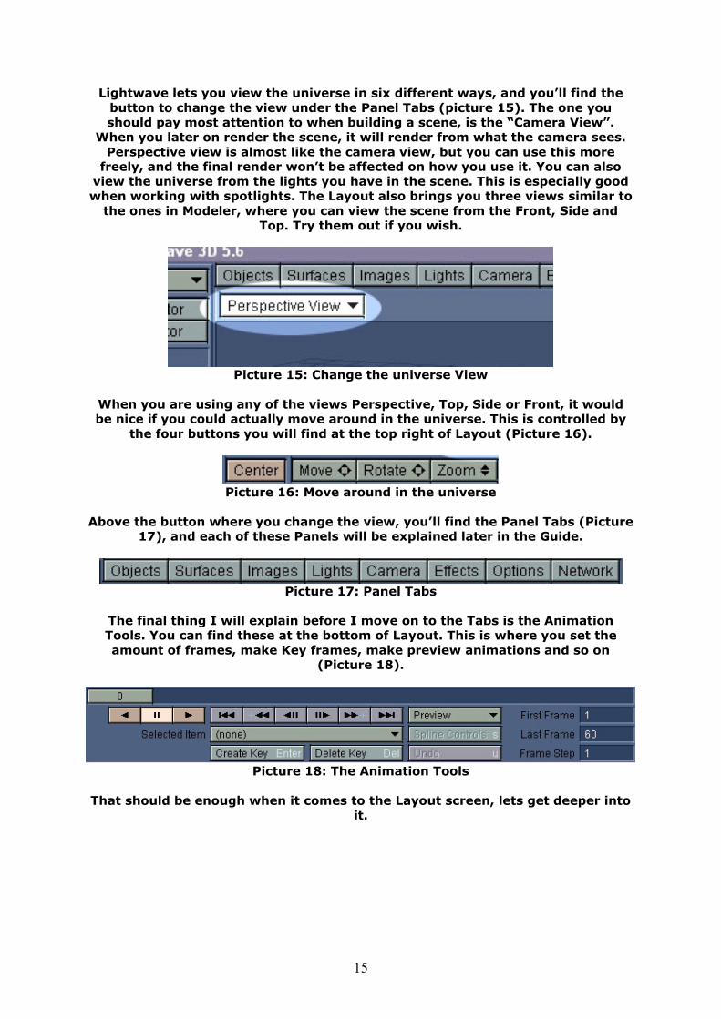
Lightwave lets you view the universe in six different ways, and you’ll find the button to change the view under the Panel Tabs (picture 15). The one you should pay most attention to when building a scene, is the “Camera View”.
When you later on render the scene, it will render from what the camera sees. Perspective view is almost like the camera view, but you can use this more
freely, and the final render won’t be affected on how you use it. You can also view the universe from the lights you have in the scene. This is especially good when working with spotlights. The Layout also brings you three views similar to
the ones in Modeler, where you can view the scene from the Front, Side and Top. Try them out if you wish.
Picture 15: Change the universe View
When you are using any of the views Perspective, Top, Side or Front, it would be nice if you could actually move around in the universe. This is controlled by
the four buttons you will find at the top right of Layout (Picture 16).
Picture 16: Move around in the universe
Above the button where you change the view, you’ll find the Panel Tabs (Picture
17), and each of these Panels will be explained later in the Guide.
Picture 17: Panel Tabs
The final thing I will explain before I move on to the Tabs is the Animation Tools. You can find these at the bottom of Layout. This is where you set the amount of frames, make Key frames, make preview animations and so on
(Picture 18).
Picture 18: The Animation Tools
That should be enough when it comes to the Layout screen, lets get deeper into
it.
16
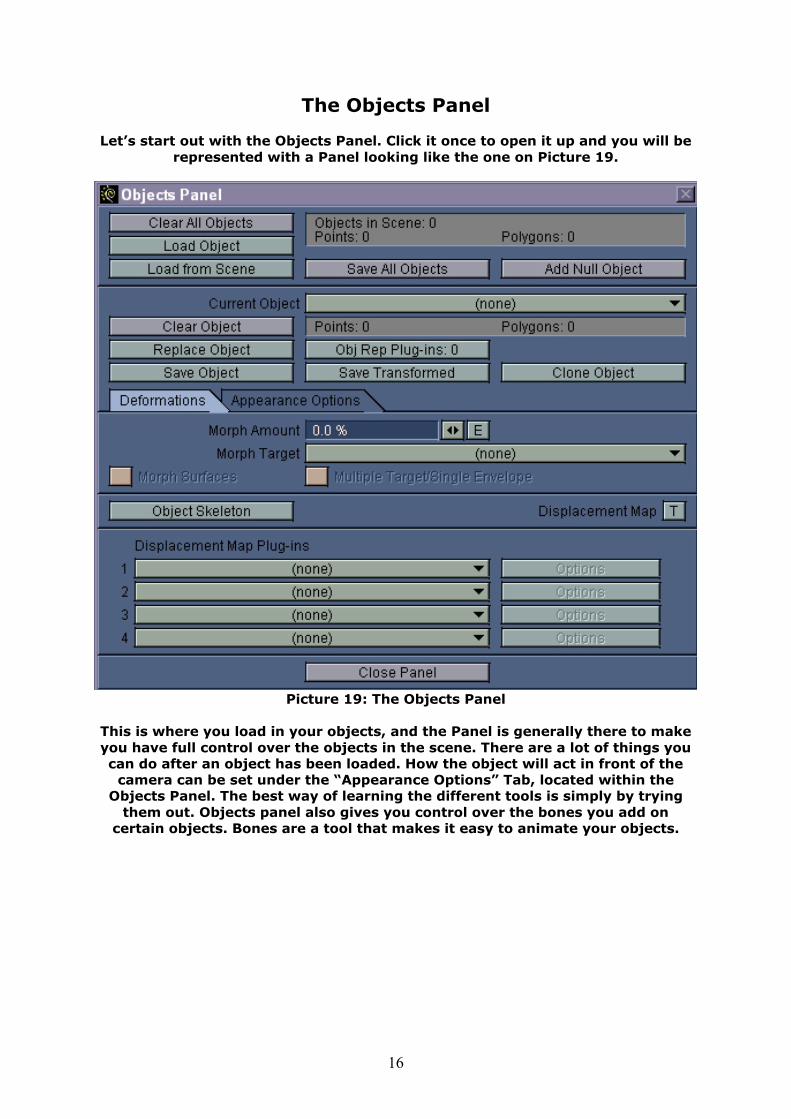
The Objects Panel
Let’s start out with the Objects Panel. Click it once to open it up and you will be represented with a Panel looking like the one on Picture 19.
Picture 19: The Objects Panel
This is where you load in your objects, and the Panel is generally there to make you have full control over the objects in the scene. There are a lot of things you can do after an object has been loaded. How the object will act in front of the
camera can be set under the “Appearance Options” Tab, located within the Objects Panel. The best way of learning the different tools is simply by trying
them out. Objects panel also gives you control over the bones you add on certain objects. Bones are a tool that makes it easy to animate your objects.
17
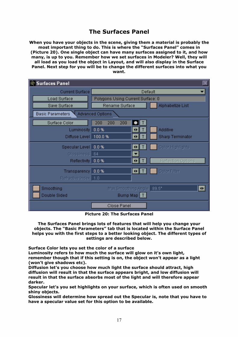
The Surfaces Panel
When you have your objects in the scene, giving them a material is probably the most important thing to do. This is where the “Surfaces Panel” comes in
(Picture 20). One single object can have many surfaces assigned to it, and how many, is up to you. Remember how we set surfaces in Modeler? Well, they will
all load as you load the object in Layout, and will also display in the Surface Panel. Next step for you will be to change the different surfaces into what you
want.
Picture 20: The Surfaces Panel
The Surfaces Panel brings lots of features that will help you change your
objects. The “Basic Parameters” tab that is located within the Surface Panel helps you with the first steps to a better looking object. The different types of
settings are described below.
Surface Color lets you set the color of a surface Luminosity refers to how much the surface will glow on it’s own light, remember though that if this setting is on, the object won’t appear as a light (won’t give shadows etc). Diffusion let’s you choose how much light the surface should attract, high diffusion will result in that the surface appears bright, and low diffusion will result in that the surface absorbs most of the light and will therefore appear darker. Specular let’s you set highlights on your surface, which is often used on smooth shiny objects. Glossiness will determine how spread out the Specular is, note that you have to have a specular value set for this option to be available.
18
Reflectivity speaks for itself, it let’s you change the amount of reflectivity the surface should have. Transparency is a way to make your object go transparent, which is a must when you are creating glass-surfaces and such. When you are creating transparent surfaces, you need to set a Refractive Index, which determines how much the light that passes through the material should bend. Bump Map is a way to make the surface look bumpy like most surfaces do in real world. You can even use your own image maps as a bump map.
Each of these has got their own “Texture Channel” settings. The Texture
Channel is reached by clicking the little “T” button that should show after each of these settings.
I will explain the Texture Channels later on when we work with objects. Lightwave is not perfect when it comes to surface settings, but there’s a way around this and it’s called Plugins. There are lots of plugins out there that can help you change the surface into what you want. The Plugins are added and
configured under the “Advanced Options” tab.
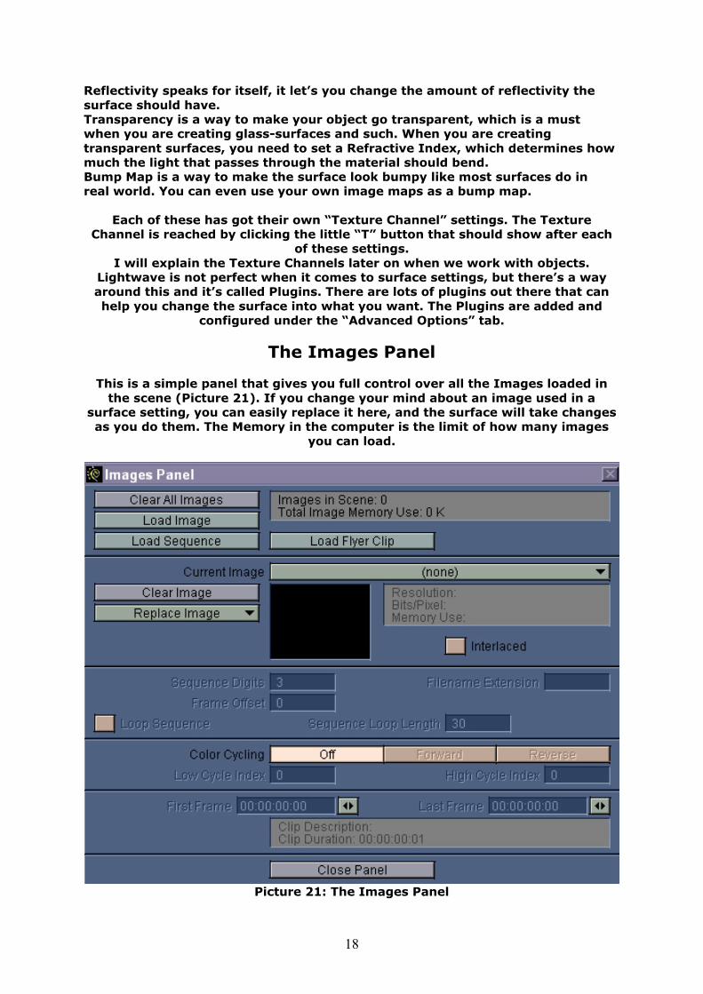
The Images Panel
This is a simple panel that gives you full control over all the Images loaded in the scene (Picture 21). If you change your mind about an image used in a
surface setting, you can easily replace it here, and the surface will take changes as you do them. The Memory in the computer is the limit of how many images
you can load.
Picture 21: The Images Panel
19
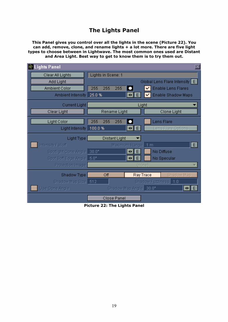
The Lights Panel
This Panel gives you control over all the lights in the scene (Picture 22). You can add, remove, clone, and rename lights + a lot more. There are five light
types to choose between in Lightwave. The most common ones used are Distant and Area Light. Best way to get to know them is to try them out.
Picture 22: The Lights Panel
20
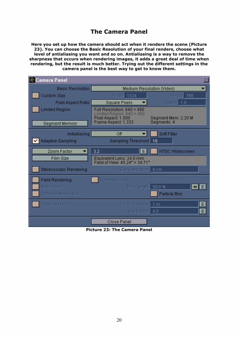
The Camera Panel
Here you set up how the camera should act when it renders the scene (Picture 23). You can choose the Basic Resolution of your final renders, choose what level of antialiasing you want and so on. Antialiasing is a way to remove the
sharpness that occurs when rendering images, it adds a great deal of time when rendering, but the result is much better. Trying out the different settings in the
camera panel is the best way to get to know them.
Picture 23: The Camera Panel
21
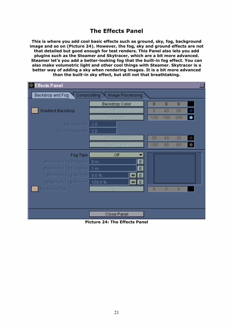
The Effects Panel
This is where you add cool basic effects such as ground, sky, fog, background image and so on (Picture 24). However, the fog, sky and ground effects are not
that detailed but good enough for test renders. This Panel also lets you add plugins such as the Steamer and Skytracer, which are a bit more advanced.
Steamer let’s you add a better-looking fog that the built-in fog effect. You can also make volumetric light and other cool things with Steamer. Skytracer is a better way of adding a sky when rendering images. It is a bit more advanced
than the built-in sky effect, but still not that breathtaking.
Picture 24: The Effects Panel
22
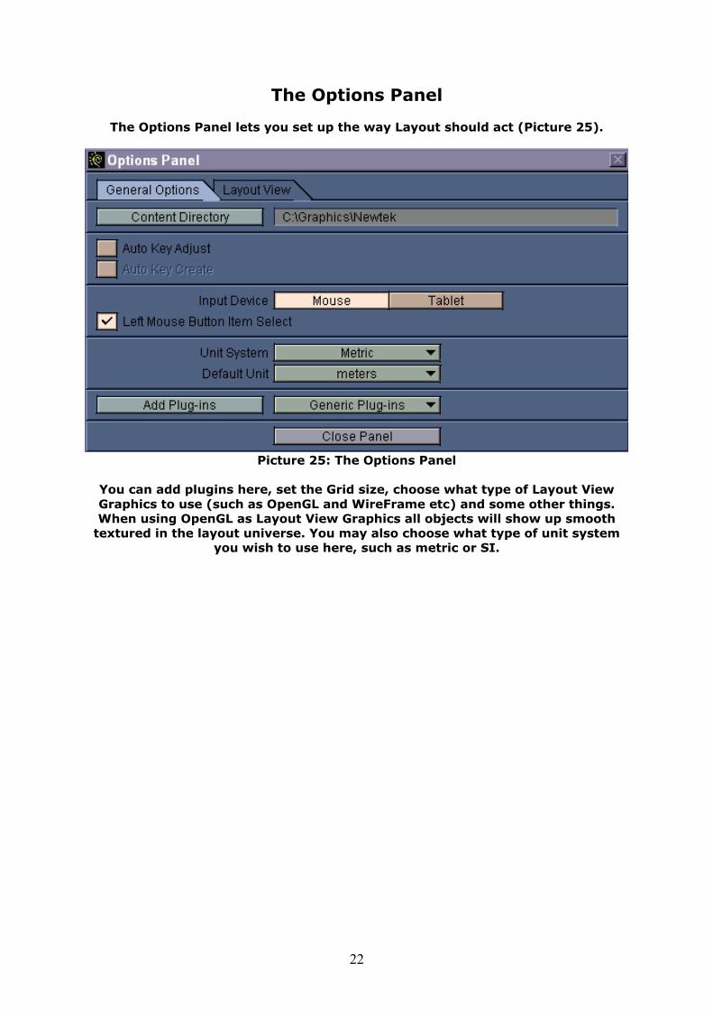
The Options Panel
The Options Panel lets you set up the way Layout should act (Picture 25).
Picture 25: The Options Panel
You can add plugins here, set the Grid size, choose what type of Layout View Graphics to use (such as OpenGL and WireFrame etc) and some other things. When using OpenGL as Layout View Graphics all objects will show up smooth
textured in the layout universe. You may also choose what type of unit system you wish to use here, such as metric or SI.
23
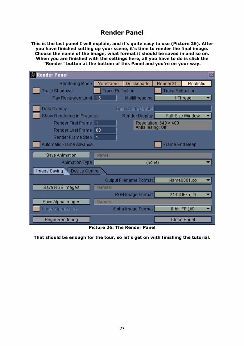
Render Panel
This is the last panel I will explain, and it’s quite easy to use (Picture 26). After you have finished setting up your scene, it’s time to render the final image. Choose the name of the image, what format it should be saved in and so on. When you are finished with the settings here, all you have to do is click the
“Render” button at the bottom of this Panel and you’re on your way.
Picture 26: The Render Panel
That should be enough for the tour, so let’s get on with finishing the tutorial.

24
Setting it all Up
Lets start with opening up the “Objects Panel”. When the panel comes up, click the “Load Object” button at the top left of the panel. Navigate yourself with the requester that comes up to the location where you earlier saved the objects we made in Modeler. We will make two scenes, so start by loading in three of the objects we made earlier, “vase.lwo”, “woodpiece.lwo” and “wall.lwo”. If you
now close down the Objects Panel you should see the three objects in the universe. If you didn’t turn on OpenGL you can do this in the “Options Panel”.
The current View type should be Perspective, but lets change it to “Camera
View”. All three objects should now be in the centre of the universe, but they should also be a bit to far away, lets move the camera!
Click “shift+C” to activate “Edit Camera”, you can also do this by clicking on
“Camera” under the “Edit” menu to the left of Layout. The “Move” option should already be selected, so lets bring up the Numeric Panel, by either hitting the “n” button on your keyboard or clicking the “Numeric” button to the left of Layout.
In the Panel that comes up, enter the following values:
X 50cm Y 1m Z -2m
Click OK and the camera should move, but wait, the vase is not in the centre of the cameras view, well lets change that to. To the left of Layout you should be able to see a button with the name “Target”. This lets you choose a target for
the camera to follow. In the requester that comes up, choose the vase.lwo from the pulldown menu. The Camera should now lay eyes on the Vase, with the wall
in the background.
Enter the “Lights Panel” and rename the current light to “Area Light”. Change the “Light Type” to “Area Light” as well. We are going to move this light to, so press “Shift+L” on your keyboard to activate the light. The Move tool should be selected by default, so bring up the Numeric Panel and change the values to the
following:
X -2m Y 1m Z -2m
Activate the “Rotate” Tool to the left of Layout and bring up the Numeric Panel
once again. The Lights Heading, Pitch and Bank should be set to 45, 35, 0 respectively.
Open up the “Lights Panel” once more and change the “Light Color” to a bright yellow (255,255,220). Decrease the “Light Intensity” to 40%. This should make the Light not so bright. Still in “Lights Panel” you should be able to find a button
named “Intensity Falloff”. Activate this and set the “Maximum Range” to 8m. This will make the light fade away a bit.
25
Next step will be to give the surfaces a nice look. So bring up the “Surfaces Panel” and select the “vase” surface from the pulldown menu. We are going to
make this a glass vase so we have to change a few things. Enter the values below as settings for the “vase” surface.
Surface Color: 150,170,190 Luminosity: 0 Diffuse Level: 10% Specular Level: 100% Glossiness: Low/16 Reflectivity: 80% Transparency: 80% Refractive Index: 1.5 Smoothing: On
To the right of “Specular Level” there should be a checkbox with the word
“Color Highlights” besides it, activate this by clicking it once. To make the glass look a bit blurry and bumpy we are going to add a “Bump Map”. You will find
the “Bump Map” button at the bottom of the Surfaces Panel, so click the small “T” checkbox to activate it. A new Panel will come up, and you should be able to find a pulldown menu where you can choose “Texture Type”. In this pulldown menu, choose the “Fractal Bumps” texture. These are the settings you should
enter for this Bump Map.
Texture Opacity: 100% Texture Amplitude: 20% Frequencies: 3 Texture Size: X = 2cm, Y = 1cm, Z = 2cm
Click “Use Texture” after entering these values and the Bump Map is set! This is enough for the “vase” texture. Change the current surface to “wall” and enter
the following basic settings.
Surface Color: 150,175,190 Luminosity: 0 Diffuse Level: 100% Specular Level: 75% Glossiness: Low/16 Reflectivity: 50% Transparency: 0% Smoothing: Off

26
This Surface will be a bit more advanced than the last one, and we are going to use an Image for it, so bring up the “Images Panel”. You need to download
image below since this is the one we are going to use (Picture 27).
Picture 27: The Bump Map for the Wall
Click the “Load Image” button in the “Images Panel” and a requester will pop up. Navigate your way to the path where you downloaded the Bumpmap.jpg
picture and click OK when you are done. The Image will be added into Lightwave, and you should see a small thumbnail of it in the little window
within the “Images Panel”. Switch over the Surfaces Panel again and check that the “wall” surface is still the one you are working with. Add a Bump Map to this surface by once again
clicking the “T” button at the bottom of the Surfaces Panel, and the Bump Map panel should appear again. This time we are going to use a “Planar Image Map”
as “Texture Type” and set the axis to “Z”. Enter the following values for this Bump Map.
Texture Opacity: 100% Texture Amplitude: 75% Texture Antialiasing: 1.0 Texture Size: 5m on all axes
Click “Use Texture” and the Bump Map is finished!

27
We will add one more texture to the “wall” surface and this will be in the “Texture Channel” for “Diffuse Level”. Just after the Diffuse Level setting you should have a small button with a “T” in it, click this once to activate it and a
new Panel will come up. We will add two textures within this panel, so enter the following values.
Texture Type: Fractal Noise Texture Opacity: 65% Texture Value: 50% Frequencies: 3 Contrast: 1.0 Small Power: 0.5 Texture Size: 20 cm on each axis
When you entered these values, it’s time for texture number two. At the top right of this Texture Channel Panel you should see a button named “Add New Texture”, just click that button once to add a new texture, and a clean texture
panel will come up. We will add yet another Fractal Noise Texture, so enter the following values.
Texture Type: Fractal Noise Texture Opacity: 40% Texture Value: 20% Frequencies: 3 Contrast: 1.0 Small Power: 0.5 Texture Size: 50 cm on each axis
That’s it for this texture channel, click “Use Texture” and you should be out in the Surfaces Panel again. It’s time for the third texture, the “wood” texture.
This one will be even more advanced, but I’m sure you are getting used to it so it won’t be a problem. The basic Parameters for this Texture should be the
following.
Surface Color: 150,70,0 Luminosity: 0 Diffuse Level: 100% Specular Level: 75% Glossiness: Low/16 Reflectivity: 0% Transparency: 0% Smoothing: Off
28
First of all we will add the Bump Maps, so bring up the “Bump Map” panel. This wood surface should look a little bit worn, so we will add two Bump Maps, the
first one with these values.
Texture Type: Crumple Texture Opacity: 100% Texture Amplitude: 10% Number of Scales: 6 Small Power: 1 Texture Size: 1m on each axis
That’s it for the first texture, so lets add the other one by clicking the “Add New
Texture” button again. In the new Panel that comes up, enter the following values.
Texture Type: Fractal Bumps Texture Opacity: 100% Texture Amplitude: 100% Frequencies: 3 Texture Size: X = 1cm, Y = 5cm, Z = 20cm
Click “Use Texture” when you are done and the Bump Maps are ready! Now we
are going to add a few textures to a few channels, and let’s start with the Channel for Color. Click the “T” button next to the “Surface Color” settings and
a new texture panel should open up. Enter the following values for this first texture.
Texture Type: Wood Texture Opacity: 100% Texture Axis: Z Texture Color: 130,50,0 Frequencies: 3 Turbulence: 2.0 Ring Spacing: 0.01 Ring Sharpness: 3.0 Texture Size: X = 3m, Y = 3m, Z = 6m
That was the first texture, and when you are done with these settings, add a new texture by clicking “Add New Texture”. This second texture should have
the follwing values.
Texture Type: Fractal Noise Texture Opacity: 100% Texture Color: 170,90,0 Frequencies: 3 Contrast: 1.0 Small Power: 0.5 Texture Size: X = 10cm, Y = 10cm, Z = 3m
29
Don’t click “Use Texture” quite yet! We are going to copy one of these textures for later use. At the top of the Texture Channel panel, you should see a
“Previous Texture” button. Click that one once so the Wood Texture shows again, and then hit “ctrl+c” on your keyboard to copy this texture. Now you can
click “Use Texture” and you should be back in the Surfaces Panel. We are almost finished now, only three textures left to add on this piece of wood, and
we are going to do that in the Texture Channel for Diffuse. So click the “T” button next to the Diffuse settings and a Texture panel should pop up. The first
two textures we are going to add here will be Fractal Noise, so enter the following values for the first texture.
Texture Type: Fractal Noise Texture Opacity: 30% Texture Value: 30% Frequencies: 3 Contrast: 1.0 Small Power: 0.5 Texture Size: 5 cm on each axis
When you are done, click the “Add New Texture” button to add the second
texture, and enter the following values for this one.
Texture Type: Fractal Noise Texture Opacity: 50% Texture Value: 50% Frequencies: 3 Contrast: 1.0 Small Power: 0.5 Texture Size: X = 1m, Y = 1mm, Z = 1mm
Finished? Ok, let’s add a third texture to this channel by once again clicking the “Add New Texture” button. Now we will use the texture we copied earlier! Press “ctrl+v” on your keyboard and the texture will be set by itself! This is it for this
channel, click “Use Texture” and we are done. Before we render this, we are going to change a few things, and we will start out in the “Camera Panel”. When
the panel comes up, set the “Antialiasing” to “Enhanced High”. Next thing we are going to do is save the objects and the scene file, so open up the “Objects
Panel” and click the “Save All Objects” button. This will save the surfaces along with the objects. Close the objects panel down and click the “File” pulldown
button at the top left of Layout. Select Save Scene and pick a location and name.
When you are done, open up the “Render Panel”. At the top of this panel, you can set what type of “Rendering Mode” you want, and set this to “Realistic”. Put a checkmark in the three boxes “Trace Shadows”, “Trace Reflection” and “Trace
Refraction”. In the middle of the “Render Panel” you should be able to find a “Save RGB Images” button. If you click this, a requester will pop up asking you
for a file name and location. Set a location you know you will find when the render is finished, and enter an appropriate name. Click “Begin Rendering” and you are finished! Now all you have to do is wait for the computer to render the
image, which could take a while.

30
Writers Words
If you made it this far in this Beginners Guide with no problems what so ever I must congratulate you to your first steps with Lightwave. The tutorial was only to show you as many of the tools as possible, yet it doesn’t cover that much. By now you should know the very basics of Lightwave, and you are ready to start
using your imagination and create your own astonishing work. If you found any errors in this Guide then please contact me and tell me where you located the error. You are also welcome to contact me with comments, improvements on the Guide, or even finished renders that were made out of the Vase-Tutorial.
The Picture below (Picture 28) is my finished render, it’s a good way of showing
how materials react with each other.
Picture 28: The Finished Render
I hope the Guide helped you and I wish to thank you for reading it.