The Jules Horowitz Reactor (JHR ) Project - NIST - JHR... · The Jules Horowitz Reactor (JHR )...
12
1 The Jules Horowitz Reactor (JHR ) Project Experimental capabilities TRTR-2005 / IGORR 10 Joint Meeting September , 12-16 2005 , Gaithersburg,Maryland - USA [email protected] Authors : C.Pascal (AREVA), Y.Demoisy (AREVA), X.Bravo (CEA), S.Gaillot (CEA), F.Javier (CEA).
Transcript of The Jules Horowitz Reactor (JHR ) Project - NIST - JHR... · The Jules Horowitz Reactor (JHR )...

1
The Jules Horowitz Reactor (JHR ) Project
Experimental capabilities
TRTR-2005 / IGORR 10 Joint Meeting
September , 12-16 2005 , Gaithersburg,Maryland - USA
Authors :C.Pascal (AREVA),Y.Demoisy (AREVA), X.Bravo (CEA),S.Gaillot (CEA), F.Javier (CEA).

2
Outlines
• Introduction
• Irradiation experiments requirements
• JHR capabilities
• Conclusion
TRTR-2005 / IGORR 10 Joint Meeting
September , 12-16 2005 , Gaithersburg,Maryland - USA

3
Introduction
he Jules Horowitz Reactor (JHR) is a modern experimental capability for studying materials
and fuels behaviours under irradiation:
-upports to Nuclear Power Plants of generations II and III,
-evelopments for future generations of reactors (Gen IV,Fusion),
Radio-isotopes production for medical applications.
•The conception takes into account :
• Fast flux performances in the core able to perform important damages on materials,
• Thermal flux performances in the reflector to reach high power on fuel samples,
• Integration of equipments allowing carrying out complete experimental irradiations operations.
TRTR-2005 / IGORR 10 Joint Meeting
September , 12-16 2005 , Gaithersburg,Maryland - USA

4TRTR-2005 / IGORR 10 Joint Meeting
September , 12-16 2005 , Gaithersburg,Maryland - USA
Experiment process phase
Experiment managementExperiment design ,Licensing process
Experiment operation , data acquisition and management
Irradiation report
Facility equipment
Customer’s
experimental
requirements
Irradiated samples
and irradiation reports
Support function processes
Inputs Outputs
Irradiation experiments requirements

5
JHR capabilities
Four hot cells : Pre-and post irradiation operations (conditioning,examinations), Alpha cell for experiments with contamination risks.
Dosimetry laboratory: Quick access of the fluence integrated by the samples.
A driver core An experimental area:located around the core, 14 experimental cubicles, I&C rooms surfaces on 2 floors, 11 penetrations penetrations with the reactor pool.
Reactor
Building
Nuclear
Auxilliary
Building
(NAB)
Support
BuildingsDifferents utilities supports (workshops) Experiments preparation with limital external transports.
TRTR-2005 / IGORR 10 Joint Meeting
September , 12-16 2005 , Gaithersburg,Maryland - USA
9 pa lettess ur 3 n iv eaux h auteur 4 .5m
8, 65m² d ’en trepos age(1t par p al ette)
DI SPOSI TIF NEUF Diam.350 x 6.5m
10,0
0m
6,3 m
Préparatio n Métaux liquide
8 m²
ZONE POUROUTILLAGES
15m²
BUREAU M AGASIN1 personne
10m²
6,3 m6, 00m
Magasin produits chimiquessurface d’entreposage 23 m²
surface au sol : 40 m²H : 2,5 m
2 pal et tess ur 3 n ivea ux hau te ur
4.5 m5,8 m² d’en trep osage
9 pa lette ss ur 3 n iv ea ux h au te ur 4 .5m
8,65m² d ’en trepos age(1t par pal ett e)
Ch
ar io
t
ele
va te
ur
(larg
e ur
t ra vé
e
3.6 m
)
9 pal ett essur 3 n iveau x hau teu r 4.5m
8,65m ² d’en trep os age(1t par pale tte)
9 palet tessur 3 n iveau x hau teu r 4. 5m
8,65m ² d’en tre pos age(1t par pa lette )
9 palet tess ur 3 n iv eaux h auteu r 4. 5m
8, 65m² d’e ntre posage(1t pa r p al ette)
6,5
0m
9 pal ette ssur 3 n iveau x h auteu r 4.5m
8,65m² d’entrepo s age(1t par palet te)
hau t
L ocal Electriquedu bâtiment
6 m²
Park
ing
Char
iot E
leva
teur
Zone de réceptionH. 5m
5,80m
2,9
5m
MAGASIN Pièces derechange
su rface entreposa ge : 58 m²volume d’entreposage : 60 m3
surface au sol : 120 m²H. 5 m
Zone destockage
30 m²H : 5m
Seuil derétention
Entreposage Métaux liquide
8m²
Conteneur ISO 20'to it ouvert
Conteneur ISO 20'toit ouver t
SASH.uti le : 9 m
Puit demontage
Seuil derétention
SAN ITAIRES
Ateliermécanique
30 m²
Stockagemécanique
20 m²
Vestiaires Rdc
Bureaux 2 p. Niv 1
Ventilation Niv 2
Hall A telier Fro id EAF~ 80 m²
H.utile : 9 m

6
Phase 1, Reception and preliminary tests
Irradiated samples (fuels and materials) : Back zone of the cells: • Vertical and horizontal connections,Storage pool of components:• Possibility to accept casks for
underwater loading.
Devices :Cold workshop: • Final assembling, • Controls, • Test benches.Hot workshop: • New fuel loading operations,• Device transfer in the facility, • Recovery of irradiated components for re-using.
TRTR-2005 / IGORR 10 Joint Meeting
September , 12-16 2005 , Gaithersburg,Maryland - USA
Vertical casks connections:
Horizontal casks connections Back zone
Front zone
Hot cells

7
Phase 2, Irradiation phase (1/3): Driver Core
• Reference core configurationHigh fluxes requirements for high dpa
irradiation (up to 16 dpa/y).
• 10 irradiations inside the core 7 small (32mm)in the center of fuel
element3 large (50mm) instead of a fuel element
• 6 in the reflector on displacement systems• 6 in the reflector on fixed positions• 9 radio isotopes production devices in the
reflector
Main design features: • Pool reseach reactor operating up to 100MWth.• Cooling and moderate by forced ciculation of light water
in pressurised circuit.• Surrounded by a modular reflector of beryllium cooled
by the pool water.• Fully compatible with radial power ramps on the fuels
samples in the reflector.
Aluminium housing
Zy gamma screens
Beryllium reflector
DE2: PWR standard deviceDE1: Material standard device
Aluminium
R=719mm
R=347mm

8
Phase 2, Irradiation phase (2/3): Irradiation devices
• Displacement systemsPerformances:
• Maximal linear power : 600 W.cm-1
(1% U5 fuel enrichissement)
• Power ramps:200 to 600 W.cm-1.min-1
In pile experiment connections
out of pile components
Fluid utilities (cubicles) ,
experimental measurements
(PF,…)
Fuel power = F( location) analytical studies
0200
400600800
10001200140016001800200022002400
0 0.05 0.1 0.15 0.2 0.25 0.3 0.35Position x(m) / core
P (W
/cm) 1.00%
2.25%
4.00%
6.00%
8.25%
6 systems around the core

9
Phase 2, Irradiation phase (3/3): Experimental area
• A Fission products laboratory
FP activities measurements in water :- Following on line the releases of FP of non tight fuels
rods,
FP activities measurements in gases : (high levels countings):- On line fission gas releases, - Activity release in case of accidental scenario ,…
FP fission gases measurements (low activities) :- Fission gas releases from HTR or GFR during stable or
specific transients,
Post-experiments measurements :- Activities of liquid and fission samples during a long
period (few days to few months),
Cells for liquid FP measurements
Cell for gaseousFP measurements (high activity)
Glove box for gaseous FP measurments (low activity)
Glove box for Post-experiments measurements
10
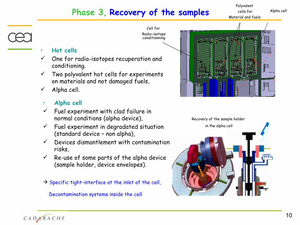
Phase 3, Recovery of the samples
• Hot cells One for radio-isotopes recuperation and
conditioning. Two polyvalent hot cells for experiments
on materials and not damaged fuels, Alpha cell.
• Alpha cell Fuel experiment with clad failure in
normal conditions (alpha device), Fuel experiment in degradated situation
(standard device – non alpha), Devices dismantlement with contamination
risks, Re-use of some parts of the alpha device
(sample holder, device envelopes).
Cell for Radio-isotops conditionning
Polyvalent cells for
Material and fuels Alpha cell
Recovery of the sample holder
in the alpha cell
Specific tight-interface at the inlet of the cell,
Decontamination systems inside the cell

11
Phase 4: Non Destructive Examinations (NDE)
• In the pools,
NDE equipments in the hot cells
Control of the global aspects of the fuel rods or material samples after the transport or after irradiation sequences,
Burn-Up & Fission Products inventory determination, Fission gas releases determination in the top of the device (LOCA experience), Verification of REA qualities,…
• In the hot cells,
Gamma-scanning Neutronography,
Visual,
Microscopy,
Eddy curents,…
CORE
Collimateur
device
Displcement and rotation system

12
Conclusion:
The Jules Horowitz Reactor ,
modern and performant has the capabilities to :
Manage multiple and various experiments,
Offer global prestations and equipments adapted with the customers needs.
Equiped with specific alpha cell and on-line fission products laboratory allowing to drive and characterise experiments on non tight samples,
With a international users-facility vocation,
the JHR will statisfy the irradiations requirements
of the MTR community in the next decades.
TRTR-2005 / IGORR 10 Joint Meeting
September , 12-16 2005 , Gaithersburg,Maryland - USA