THE JOURNAL OF GEAR MANUFACTURING 1Iddn::~ •.;IiangelL '0 GEAR ... seed money for research, ... is...
52
TEe H N 0 LOG Y THE JOURNAL OF GEAR MANUFACTURING -- - - JULY I AUGUST 1991 GEAR LUBRICATION - PART III MULTI-THREAD HOB CUnlNG DIAGRAMS REVERSE ENGINEERING SHOP FLOOR - HOB TYPES PACIFIC RIM GEAR MANUFACTU IN
Transcript of THE JOURNAL OF GEAR MANUFACTURING 1Iddn::~ •.;IiangelL '0 GEAR ... seed money for research, ... is...

TEe H N 0 LOG YTHE JOURNAL OF GEAR MANUFACTURING
-- - -
JULY I AUGUST 1991
GEAR LUBRICATION - PART IIIMULTI-THREAD HOB CUnlNG DIAGRAMS
REVERSE ENGINEERINGSHOP FLOOR - HOB TYPES
PACIFIC RIM GEAR MANUFACTU IN


'etolook atHotler~_I'erent
ItS •
•maWe've added a.newdimension in serviceand support to ouracb'anced .3-Ugear-measuring machines.
!If you haven't looked at us Ilately,.here's some big news:Ho11erCNC gear-measuring machines andlsoftware now comefrom the Industriall Measuringl Technology Divisionof Carl ~eissi Inc., a world leader ln coordinatemetrology equipment.
As the ,gear experts at Zeiss, Hofler isnow more responsive than ever. Our full-servicelocations across the U,S, provide whatever youneed-sales, operator training, maintenance orreplacement. parts.An extra dimension in speed and precision.
All Hofler machines feature a unique three-
dimensional probe head that allows faster, more accuratetesting of profile and !Iead. Even the simplest Hofler modelis more precise than any competing machine in the industry.
Hofler products include the ZME series for cylindrical·gears, the EMZ series for universal gear measuring, and theZMC model for your most demanding laboratory, 3-D andbevel-gear applications. You can also choose from threedistinct software packages that run on a networked or stand-alone IBM AT-compatible or Hewlett-Packard computer.CaUtoday for literature or a demonstration,
1-800-888-1967Ext 51Or see your local Zeiss representative.
Carl Zeiss, Inc.
IMT Division7008 Northland DnveMinneapolis. MN 55426612· 533·0225

Cover photo courtesy ofS' America, Inc.,Oak Park, ML
'CONTENTSJl'J.Y/,\l'(;lTST, 1991
FEATURESThe ILubrica1iutli of' IGears • Part InB}' R o b e r I E r r i c h. e I I 0'
G~ARTE H. Albany, CA, , , " '. , .• ' '. ,."""""""""""",,14,
MuJti- Thread Hubs, With New Cutting IDiagram;,B y N j k o I a y S TTl i r II o I'
Volgogrod Polytechnical lnsurure, Volgograd, USSR. , , ,', , , , , , , , , , , , , , , , , , , , , ' , , , , , , , , , • ' , , , ,21
SPECIAL FEATURESGear rundamentals:Reverse, EngineeringBy Yefim KOllyar
American Pfauter.Ltd. Love Park. IL."""." .. ", •. , ... , ... ""., ...... ".,,, ..... :34
D'EPARTMENTS~blishers PageOur publ isher comments on
the US gear industry ....•. , .. , ., .. , " ,,' , • , . , , , , .•. , , • , ••. , •• , , . , , , . , , , • , , , • ' , , • , , , • , , , , " 7
Vi~intPacific, IRim Gives Stiff ICoqJetition Tb US. Gear ProducersB v Joe A r \. i II
A~W G ar Co" Downers Grove, n,.......•...•...•........................................ 9
AGMA, Gear Expo 1S1., 11r1he!Woddllof IGearing"Biennial show comes to Detroit. , , , , , , , , , , ' , , , , , , , , , , , , , , , , , ' , , , , , , , , , ' , , .• ' ,., • ' .•.•••... '12
EXhibitors Ind'exAdvenisl;;f!>cxi1ibiting at Gear Expo '91.. ,",', .. ,""""""""""""'" 13
.Advertiser IndexFind the products and services you need ,,40
Shop' R'ooI' __ _ _ _ _Pines,Pples. Corncobs & Other Hobbing Matters81,' William La n n i n c k
n~,Lincolnwood, IL. , ,.,.".,", " .. , •.... , 411
ClilSSifiedsProducts, ervices & 'information you can use,., ... ,., ... ,." .. ,.,', .... " .... "",.44
CalendarEvents of Irueresr.. , .. , , " .. " ,.,',.,',.,".",.,',.,',.,", .. , , .'46

Now use your AMERICAN EXPRESS, Visa,or Master Card to subscribe to
$4'0.0'0 for 1 year (16 issues) in the U.S.;$50.00 in Canada; $55.'0'0 elsewhere,
Calli (BOO)451-8166 to place your order.
Subsidiary 01 Star Cutler Compaf1'/
.2234 S. Dam Hoad, West Branch. Mil 4866,1517/345-7160 800'/426·2538 (From MI)1580 Progress Drive, Richmond, IN 47314
317/935-7424 80'0/686-3158 (From OIH,INI)I
CIRCLE A-4 en READE R' REPLY CA'RD
,4 GEAR TECHNOlOQ,y
GEAR TECHNOtOGY,·;nrrOI{U] .
Publisher & Editor-in-ChiefMichael Goldstein
Associate Publisher & Managing EditorPeg Short
Senior Editor Nancy Bartels
Publishing Assistant Kelli R. Hopkins
Technical EditorsRobert Errichello
William L. JanninckDon McVittie
Robert E. Smith-
,\RT
Art Director Jean SykesAn Director Jennifer Goland
;\URKETIN(;
Advertising Sales Manager Patricia Flam.
Sales Coordinator Mary Michelson
IU;\ilUI.J. PUBI.ISIII;\;(; ST,\FF
President Michael Goldstein
Vice Pre ident Ricbard Goldstein
Vice President/General ManagerP~g Sllor1.
Controller Patrick Nash
Accounting Laura. Kmnane
Admini strati ve Coordi natorDebbie Donigian
Art Con ultant Marsba Goldstein--
R,\:\'[),\I.L I'llBJ.lSIII:"\C, rxc. '
1425 Lunt AvenueP.O. Box 1426
Elk Grove Village, IL 60007(708) 437-6604
\ ()L. S. xo -I
GEAR n:CltNOUXi'i. 1'h< J.. EUI 01 c..... H .. .r...l!Iinl {lSSN0J43-68!iKI II pYb~i'i.hed bil1lOl'Io.ly by Randll]1 .Pub1i~hlng. J~ .• 1425 L.unl
A'RfIUC'. P.O. Box 1426. EJI;, Of1J-VCVm.IL 6O:XJJ. Subsc:rlpt.Ki'D f'IIa.:!P:
S40-.oo in rbe u.s.: 550.00in Canada: S!5oS.00 in 1111«he.r-t::ountriel. Secom1.cJaSJ;poYq;t paKi &1 ArlinJI,loo Ht.l,lhts" IL IlId .at iDiiDOOIll1ll.Uin& office-
!pm.:lInastcr. Send 1Iddn::~• .;IiangelL '0 GEAR TECHNOLOOY, 'YlIe JOOl'1\1l!
of(k.ar'ManurlliL1:u:rini. 1425Lam Ave:nue. P.O. HUiI .426.:EJkOtuiICVlllqe.IL, 60007.
CIConte-lfI~oopyrt:ihl:edby RANDALL PUBUSHlNCl. (Nee> 1991. Anh:le:.~n& m GEA.R TECHNOLOOY mil)' fIICIIIlx rcpr1l'duccd in wbolc IX' in pitt
withnLlI the: ClIpn:::i!i pc:iTi1i1i~ion of the publimct ortlk: iiu!bur.

Use Dressable'.' CBN Wheels• SGWheel's
.' Direct Plated CBNWheel:s
• 3 Grinding spindles availableWhee'l speeds 2000 to 24000 RPM
Std. Spindle 20 IFII.IP.
Versatility
Intro~ucinglthe
Oerlikon - MAAGOlpal420
WITH IINTEG:RATED W-HEE!L DRESSER,17HE GEAR GRINDER OF CHOICE
FOR TODAY'S VARIED HIGH PRECISIONAND' HIGH PRODUCT10N REQUIREMENTS."
Review ¥our Choicesfor
Flexibility - Productivity ...Accuracy
33 Teeth - 3. t D.P. - 4" Face -11.7" Dla. - 20" P'.A, - 20" HalixMal. 101Ni Cr Mo 7G - Case hardened 10 SORC
Ground wilh TIp IRelief &. Lead Crowt1
AGMA10Tot. Grind w/dressing
5.2 min.
.AGMA13Tot. G~indw/dress'ing
10.7 mln,
On Screen Optimization
ot ProfUesand Crowning
IRotaryand Lineal Crowl1Iing
Double FlankGr,inding
Singl'e FlankGrinding
CALL (7'08) 8,1'0-005'0 FAX (7.08) 81 '0-989950.21 Chase ,Avenue. Downers IGrove, IL 16'0515
• Photo courtesy of IPE, line., Barrlngt.on,llCIRCLE 1.-5 on' READE R' REPLY CA.RD'

Part blank andgear cutting tools,
play .criticall roles ingear quality control.
We offer optlcnal soft-ware packages for in-
specting gear blanks forcircular geometry and gearcutling tools such as hobs,
shaperlshaver cullers,and broaches.
Gear Testing USing Generative Metrology tech-l!'Iiques is, en'irlaJ1cediby' e,amputerlzed auto-
mallon and analysis. True Index, Ilead,and involute testing are performed
as the lest part and probe areengaged lin inler.relatedcontinuous move-
ment. Flotary and linear axis are synchronizedas required by the test.
IndexProcess control can beImplemented by anal-
yzing data collectedIn gea'l testing. Weoffer $PC software
to, evaluate x-bar; Fl,histogram, and
tooth surfacetopological
studies.iHistogram
3012-4QC 'Gea.r Analyzer isone of ,a family of our gear
and gear ,cutting tool ana'l:yzers.For a free lull-color brochure'
describing our Gear analyzers,write or call M & M PrecisionSystems, 300 Progress Ad.,West Carrollton, OH 45449,
5131859·8273, FAX 5131859-4452.
~'IYI&M ~1EI~C'SICJN_LSYSTEMSAN ACME·CLEVELAND COMPANY
CI RCLE ".oS en READER R EPI.. Y CARD'

ProppingUp The Falling Sky
"So Henny-Penny, Cocky-Locky, Ducky-Daddies,Goosey-Poosey, Turkey Lurke», and Foxy- Woxy all went to
tell the king the sky was a-falling. "- Old English Fairy Tale
D he sky may not be exactly falling for thegear industry. but things have been bet-ter. Last year's "332 Report" and therecent Department of Commerce "Na-
tional Security A sessment of the U.S. Gear In-dustry" have confirmed what many of u haveknown allalong- thatthe U.S. gear industry, ifnotactually sick" is certainly not in the best of health.Meanwhile, Joe Arvin's report, found elsewherein thi issue, suggests thatoverseas gear manufac-turing is getting healthier. [fthe situation rem ai nsunchanged, the future of our industry could bebleak indeed.
The question now is"what do we do about. it?The problems facing the industry are tough
ones. Many of them. like an adequate supply oftrai ned workers.are part of much larger probl emsthat confront our nation as a whole, Others, likethe internal industrial policies or the differingcultural and 'economic expectations of our over-seas competitors, are not open to "quick fixes" .assuming they're "fixable" at all. Some, such asthe disparity between wages paid here and else-where, while still significant, are not as crucialas they once were, blu have been replaced byothers just as rough, like our own cripplingnational debt and balance-of-trade problems.
But we can't just sit around wringing ourband; nor is it enough to go crying, "The sky i .falling!' We have to tart addres sing the questionof what SPECIFICALL Y we are going to do torestore the health of our domestic gear industry ..
First, we have to hed the notion that simplylobbying Congress will be the solution to all ourproblems. Government can help the gear indu stryin some ways, but we have to go to our supportersin Congress with specific plans and ideas. If
investment tax credits, subsidies for training,seed money for research, or more protectionisttrade legislation are what we think we need, thenlet's ask for them, Meaningless cries to be pro-vided with a "level playing field" or a generalizedwail to "Do omething!" are not enough.
Furthermore, we should remind ourselves thatthe ride on the government gravy train is comingto an end. Governmentmoney, either from outrightgrants or tax breaks, isgoing to be much harder tocome by in the future. Ironi-ealty, our crushing nationaldebt is part of our problemand adding to it, no matterhow good the short-termgoal, doesn't help.
We also have to face thefact that some of our prob-lems cannot be solved by thegovernment. The internaleconomic policies of othercountries are beyond our con-trol. as are the customs andpractices that may give thema competitive edge. Insteadwe need to reform our ownpractices.
The solutions to the gearindustry's har'd, intractable problems will have tocome from within the industry itself, Perhapsgear manufacturers need to begin to take a differ-ent view of who their competition is. The term"global village" is fast becoming a cliche, but itis an accurate description of the current gearmanufacturing climate. Ifinvesrment and
PUBLISHER'S PA'GE
'1JlILY/AlIGlIST lee'

fuUy Ilmplemenl.ed SPC,. and datacommunicalions capabilities., utilizing
. slate 01 the art CMMi's andl M & M precIsion~_ gear checker to 30" dlamster to 18" face.
. 5airian e (lear, .!)nc.P.O. BOX 409, PLYMOUTH, MI48170
(313) 459-24411'In Mich. 1·800·48.2-1773· FAX (313) 459·2941'
QUALITYGEARSUP TO AGMA 15, Mll-I-452D8A & Mll-STO-45662
FROM A SINGLE GEAR TO LONG RUN PRODUCTION, INCLUDINGPROTOTYPE & EMERGENCY REPAIR!REBUILD SERVICE
SIZE RANGE FROM UNDER l' to 4B" DIAMETERRelishauer GlfOund IG,earsMost TYP,e,Ge'ars lMIanutalctUlF,edComplele'lo Cust.omlerSpecifications
• METRIC OR AMERICAN STANDARD• SPUR, INTERNAL & EXTERNAL.' HELICAL. INTERNAL & EXTERrtAL.' WORMS, WORM GEARS• SERRATIONS •. SHAFTS• SPUNES, INTERNAL & EXTERNAL• SPROCKETS. CLUSTERS• SEGMENTS • SPINDLES• RATCHETS • GEAR BOXES
'CIRCI.!EA-9 on READER IR!EP.I.YCARD
IT'S TIME T'O ADVERTISE
INGear Technology.
Don't let the
competitionget the
edge!
~ Reach decisionmakers around
the world ..
It's hightime youcalled.
(7'08) 437-66'04
8 GeAR TECHNOLOGV
training decisions are made on the basis of only
II! what.domestic competitors aredoing, U. S. manu-facturers are missing the big picture.
If present conditions remain unchanged overthe next fifteen years, many current dome tic gearmanufacturers may not be in business. A moreprudent strategy might be to take a long hard look:at what the most successful manufacturers, nomatter what their location, are doing. They're thepeople whose game plans U.S. gear manufactur-ers should be studying and trying to better,
For whatever reasons, our European and Pa-cific Rim competitors are more willing or able tospend money on state-of-the-art equipment andlong-term training. A telling comment on thepresent state of gear manufacturing in the U.S. isa report from Gleason Works: They have takenorders for over I 00 of their new Phoenix gearsystems, a little less than. 20% of which are goingto the U.S. market. The rest are going overseas.
Why is that?It seems as though the American gear manu-
facturing industry is waiting for the other guy toI
I., II PUBLISHER'S PAGE
move first No one wants to spend the money orrisk the short term profits for the sake of a long-term advantage. But refusal to run the risk is self-defeating in the long-run,
Perhaps U.S ..gear manufacturers need to askthemselves the really hard question: Do Iwant tobe manufacturing gears 20 years from now? Iftheanswer is "No," thenthe present course fine. Ifthat vision is not one that is attractive, then thetime bas come to make some other choices.
Someone is going to have to have the courageand foresight to make the first move and do thecreative investment in the future.
Tough? Yes. Risky? Doing nothing is riskier.Necessary'? Absolutely.
Only after we have gone through the soul-searching and brain work necessary to developspecific plans for pulli ng ourselves up by our ownbootstraps. and then summoned the courage tomake those plans work, can welegitimately go toothers to demand solutions. Running about likeHenny-Pennyand her friends. crying. "The sky is
f.lh.g!" is notenQUgh~ b..PublisherfEditor-in-Chief

Pacific Rim Gives StiffCompetition To U.S. Gear
Producers
This past fall. Ihad the
~:j:p:~~~;:~~~:~~wan, and Singapore
to witness first-hand the sta-tus of the power transmis-sion and machine tool in-dustries in these areas.Pointsof interest includedequipment, material han-dl ing, ccnrputerization,wage and tax. structures.m-ventory controls, and
that have doubled or eventripled in thela t ten years.
For example, when Irustvisited the Kohara Gear In-dustry Company of JapanDine years ago, their facilityand equipment could best bedescribed as modest. On thistrip, I found that they havedoubled in size and have re-cently added a second loca-tion. They are now equippedw:ith the latest machine tools
workforce attitude. and are doing CBN and dia-On this year's tour, Iwas mond grinding of'spurgears,
accompanied by 24 other They aliso have a Gleasongear industry managers,government personnel, andpeople affiliated with the[NFAC program. During ourI7-day trip. we visited sev-eral raanufacturers of loosegears, power transmissioncomponents, and machinetools, and geartraining andresearch in titutes.
Tbeir FacilitiesThis trip was my third
visitto the Qrient. In view ofwhat I had seen on my lastvisit in ]985. industry in theseareas has experienced vigor-ous growth and has institutedmas ive reinvestment. Wecontinually saw facilitiesequipped withthe latestCNCequipment. Many compa-lilies were reporting sales
Phoenix cutter and grinderon order. For any gear com-pany to double its size inniae years is remarkable.
Another example of thegrowth rate of Pacific Rimmanufacturers is OkuboGear Company. also of Ja-pan. Okubo has tripled in sizesince 1979 and now has atotal land package of 13.8acres with 5.9 acres of build-ings combined in two!oca-tions. Considering the scar-city and high cost of land inJapan, the extent of theirgrowth and reinvestment isquite evident,
A final example of the in-dustrial. growth in these areasis Tong Il, a Korean manu-facturer of power transmis-
Joe Arvin
VIEWPOINTsion components and machinetools. In 1985, Tong n wasoperating as a producer oftransmissions and axles forautomotive applications,and they were also just be-ginning to expand their prod-uct to include machine tools.With sales of $60 million.they were projecting 1990saliesof$253 million. Actualsales for last year were $430millinn. They hadunderesti-mated saJes by $177 million.We saw hundreds of Tong Ilmachines throughout Koreaand Taiwan.
In terms of technology.the facilities we saw wereas good or better than thoseof most gear companies inthe U.S. They are no longeroperating with just a fewpieces of high precisionequipment. 11'1addition,tile majority of the COID-
panie reported that sub-stantial percentages oftheir annual. sales were be-
ing allocated to researchand development.
The remarkable growth ofthese companies was not theonly change we saw, Other,more subtle changes weretaking place as well.
While the participative ap-proach made famous by Asianmanagement in the 70s and80s is till in use, there is lessrelianceonitnow, Thechang-ing attitudes of the Asianworkforce ~ which W will ad-dress later - may account forthis change.
In the majority of the plants
,Joe Arv:ilnis the President of ArrowGear Co .. Downers Grove,tl; Oller tire last nine yearshe has conducted industryinformaiiona! tours to gearmanufacturing countriesaround the world.
JULY/jI,U!lUST '99' '9

we visited, we saw extensiveuse of automated machineloading and material han-dling. We also saw that inmost: cases, operator wererunning several machinesalone time ..
While their equipment.technology, and (in mo t
case) housekeeping werequite impressive, we did seemuch less concern for opera-tor safely than most of us areused to. In some plants wesaw operators lifting heavyobjects and people workingaround machines withoutsafety glasses. In one plantwe even saw operators wear-ing sandals in a work areawilh chips on the floor.
Throughout the 1980s.American indu: try wa pre-sentee! with numerous ar-ticles, books, and seminarswhich extolled the virtues ofJlT (Just In Time) manufac-turing. During our planttours, we were able to seeJTT in its "truest form". We
Singapore. 3-3.50. Thesecountrie experience an av-erage unemployment rate ofonly 2%.
An interesting note onwages is that:on my last visitto Korea in 1985, the averagehourly wage was around$4-5. Tile current aver-age of $7-8 i a substan-tial. increase in just fiveyears - a clear indicator ofvigorous growth.
The work ethic of the Asianworkforce remains very in-teresting. Traditionally ..Asian worker have a renseof duty to their company ..Peer pressure to achievepeak productivity and avoidbeing a "di. grace" to thecompany is intense. Thislevel of dedication eemedapparent inthe plants we vis-ited, ]n more than one in-stance. we sa w operators run-ning from machine to ma-chine, But this ethic may bechanging.
Each of our technical visitsaw thousands of finished would end in a question and
goods waiting for shipment-110t quite the 2-l/2I1our in-ventory we had heard somuch about.
Their P,eop.feTo better explain the
character ist.ic s of theAsian workforce, let mefiist mention the order inwhich the countries that wevisited rank: in terms of in-dustria] development Firstis Japan, followed in de-scending order by Korea,Taiwan. and Singapore.Wage in these countrie aredirectly proportional W
their tatus in (his hierar-chy. Hourly wage in Japanare $13-14; in Korea, $7-8;in Taiwan, $4-5; and in110 GEAR TECHNOLOGY
answer session with companypersonnel. During these ses-sions, we asked thl particu-lar que tion: "Ofthe follow-ing. what do you feel is yournumber one problem?
• Lack of sufficient capital;• Personnel problems;-Adequate engi.neering
support to produce qualityproducts that would be com-petitive in the world market."
Surpri ingly each COIII-
party's response was the same .."Personnel problems" weretheir number one concern.
After further explanation,it appearedthat employeesare starting 10 refuse over-time and prefer a 40-hourwork week. One Can specu-
late thai this is becauseworkers are lartjng to accu-mulate more dispo able in-come, and they want morefree time to spend it, Somemanagers a1:80 told us thattheir workers are becomingmore "belhgerent". Some ofus felt that it was not neces-sarily belligerence. butrather that their workerswere becoming more "west-ernized", Perhaps thi is aninevitable side-effect oftheir industrial growth.
TrainingAs in earlier [rips, l was
impres ed with the amount oftraining being done at thesefacilities. Training i just
ties - Philips GovernmentTraining Centre and Preci-sion Engineering Instil ute(PEI) .. While PEl is largerthan Philips, both facilitiesoperate for the same pur-po e - to Iraira young peoplein precision engineeringand machining skills.
Both facdirie offer two-year programs. Inthe firstyear, students learn ba iemachiningtechniques, In thesecond year, their studies involve computerized machin-ing (, AD-CAM). where Iheyacqui re classroom and hands-on experience in the opera-tion and programming ofCNC machine tools. Their
------- -
VIEWP,OINTAsian w'ork,ers ate becoming moreWest,ern~
lzed, sometimes Irefusingl overtime and pre-
ferr,ingl a 40-h.our wo:rk weelk. S·ome 01 the Iii II'
manag:ers see these ,chan'ging .attitudles as
!!bellligerent,1! when they may simp,ly stem
course of study also encornpasses a full range of manu-facturing processes. Thesefacilities are equipped withstate-of-the-art equipment.At PEl. we estimated ap-proximately $25 million inequipment on the hop floor- the vast majority of whichwa brand ne w.
Graduates from these pro-grams are sent intn theworkforce with high levelsof skill, yet they will earnonly modest salaries. After
from the desire fer more II!eisuII',etime in
which to spend increased income.
another accepted aspectofthe Asian worker's job; andjudging by the acceleratedmove into computerized in-dustrialization. this commit-rnenrto training is e sential,
Governments in the Pa-cific Rim. particularly indeveloping countries likeTaiw311 and Singapore. areactively involved in apport-ing industrial training ..
While in Singapore, wevisited two. governmentsponsored training facili-

graduation, pm students canexpect to earn $330 permonth. After five years ofon-the-job training. they canprogress to $720 per month.
cared at the Illinois lnsti-tute of Technology inChicago. [NF AC will of-fer formal. training pro-grams in gear technology.
I'm sure that any U.S. gear In addition, the fac.ili tycompany would love for some- w W c 011 tain 0 fa stat e -one tocome looking for ajob o f.- the- art mac h in in gand say, "Iknow how to pro-gram my own machine. lknow how to operate turn-ing, milling. drilling andgrinding equipment. I un-derstand tempering andrehardening and their majorcauses. and on top of that,[' II work for $3 per hour ..'
The fact is that the PacificRim 'sposture as a competi-tive force will conti Due 1.0
increase largely because it isso far ahead of the U.S. in theimplementation of training.
And why doesn't the U.S.gear industry train itsworkforce to this extent?Speaking for Arrow Gear.the reason we do not is thatour domestic competitorsdon't. Adding the cost ofthis extensive training toour product would result inanuncompetitlve priee. Yet,a trained workforce is es-sential. in meeting the in-creasing preci ion require-ments of eurindustry ..
This no-win : eenario hasbeen a ouree of great con-cern in the gear industry forsome time, although I be-lieve we are finding a solu-tion to this dilemma in theINFAC Program.
The ]NFAC Program,which stands for Instru-mented Factory, is a gov-ernment-sponsored pro-gram aimed at providing as-sistance with its trainingand research needs to theU.S. gear industry. Lo-
shop where new pro-cesses can be studied andstudents can obtain hands-on experience.
I believe the benefits westand to gain from this pro-gram will bees sential incom-peting with the highly tra inedworkforce and the high preci-sian capabilities of PacificRim manufacturers.
In ConclusionThis visit renewed my
concerns for the competitiveability of Asian manufac-turers. Their massive rein-vestment, technology, andtrained workforce makethem a formidable threat.
However, it's not too latefor the U.S. gear industry.With a commitment to on-going improvement andgrowth, cooperation, andplain hard work. we can suc-ceed. But each of'ushas to doour best!
For anyone interestedin additional informationon the findings of'this tour.a videotape of the trip'shighlights will soon beavailable. Consisting ofboth video of our plant vis-its and comments from tour '!
participants, this programwill provide a detailed andinteresting insight intoAsian manufacturing. Formore information on or-dering. contact the officeof Dr. Maurice Howes, Di-rector of INFAC at (312)567-4200. I.
COIMPLETE GEARMANUFACTURING SERVICES
IP,referred,Quality SuppUert'o ElighlMa)o.rCorporaUons
• Spur and! Hefical Gears·1" to 16"0.0.• Shafts up to is''• CNC Inspection oi
Gears and Splines• Machine onl.yor
Complete• Broaching• CMM Inspection
Capability• Gear Grindingl Ability
.•5 PcsJ100,000 Pes.per month
• Assemb'lies or ILooseGears
• Crown Hob or Shave• Precision Machining, and
Gear Blanking• Precision Shafts and
Splines• 'Gerotors,• Shaper Gutting
Call1eaay to dl'scuss your s,peclflcatlolls.
@-REEF· BAKER CORPORATmON.
50903 E. Russell. Schmidt Blvd. MI. Clemens, Ml48045(313)949·2520 Pax: (:'Il3) 949":1411\
_ _ ®CI ReI.IEA ..S on READER: IREP,I.Y OA'RO
A'GMA FALL TECHNICAL MEETING 1991
October 23 -25, 1991Det:r'oit,Michigan
,For more Informa\tion contact:.A'GMA Headquarters1500 'K,ing Street, Suite 20'1AI~exandria. VA. 223114Ph: 70:3/684·02111 $_>Fax.: 703/684-0242
CIRCLE A.-3BoIIIREADER IREPLY CAR.D
JULY,"UGUST 11191 11

Explore"The World of Gearing"
Detroit.
AGMA's Gear Expo '91, "The World of Gearing," opens
October 20 and runs through October 23 at the Cabo Confer-
ence & Exhibition Center in "The Heart of the Manufacturing
of the Detroit River in downtown Detroit and provides easy
access to a variety of hotels, restaurants, cultural atrrac-
tions,and historical. sites.
KeHi R. H'opkins
Industry," Detroit, MtGear Expo '91 is "the largest
trade show ever specifically organized for the ,_ ~~ ,
gear industry," according to' Rick Norment, ~O·.~ I
A:GMA's Executive Director. !JIGear Expo. started in 1986 as a O·
table-top exhibition and has grown
into. a full-fledged trade show. The
EXP,o is held every two years on a 0rotation schedule among several cities. 0Detroit, the oldest city in the Midwest, ~Oespecially "" it,seU to this trade "" lie",The "MDtDrCl~Y" IS the heart of America's manu-
facturing base and produces millions of gearsets each year.
'Gear Expo '91 will provide 35,000 square feet of exhibits
by 79 companies from around the world. This forum offers
gear manufacturers and suppliers an opportunity to exhibit
their products and gives visitors the chance to make compari-
sons of the products and ask company representatives ques-
tions right at. the show. An index of Gear Technology
advertisers who are exhibiting at this year's expo can be
found on the adjoining page,
Products and processes on display include broaching,
custom gears, cutting tools, finishing, forging, grinding,
heat treating, bobbing, inspection.Jubricating, milllng,
shaping, shaving, and testing, to name a few.
The Cobo Conference & Exhibition Center is on the banks
12 GEAR TECHNOLOGY
Transportation in the downtown area is a matter of
M, C. . personal preference - visitors can choose from a
It~· variety of unique options. Downtown
I ,Q.". Detroit's elevated transportation sys-
.,. tern, The People Mover, carries people
ana 2.9 mile track around the central.
business district. Buses, rental cars,
,. taxi cabs, and antiquetrolley cars are
. : other travel. possibilities, Parking is no
, problem - there are 2,200 spaces at the
_ .~ ') ~ Coho Center and 3,000 spaces at the adjoin-
2,0,ng Joe Louis Are.113.
Show hours are ]2:00 p.m. to 6:00 p.m ..on Sunday; 10:00
a.m, to. 8:00 p.m. on Monday; 9:00'<lI.m. to. 6:,00 p.m. on
Tuesday; and 12:00 p.m. to 4:00' p.m, on Wednesday.
Once again the AGMA Fall Technical Meeting will be held
in conjunction with Gear Expo. The FfM win be held on
October 23-25 at the Westin Hotel, Renaissance Center, a
short distance from the Cabo Center. This year's meeting has
been expanded to allow for more presentations. Tile papers
will feature a variety of gearing subjects, including 3-D
contact analysis, gear tooth friction, gear stress distribution.
oil jet gear lubrication, andlow noise marine gears.
For more information on either the 1991 Fall Technical
Meeting or Gear Expo '91, call AOMA Headquarters at (703)
684-021 L i.

Booth No. 715-717-71.9'AGMA1,:500K'ing Street, Suit.e 201Alexandria, VA 22314(703) 684-0211
Booth No. 337marmo Gear Com:pan
P.O. Hox 1.789Amarillo, TX 79'105(806) 622-1273
Booih No. 137Amer,ican Metal TreatingCompanyW43 East 62nd StreetCleveland,OH 44103(216) 431-4492
BooI.ll No. 5,39Amer,ican Oerl.ikonS021 Chase AvenueDowners Grove. n.. 60515(708) 810-0050
Booth No. 301American Pfautel' Limited1351 Wind or RoadLove P,ark:, n. 6 H32(815) 877-8900
Booth No. 433HHS - Honer MascbinebauGMBHP.O. Box 1453 EttlingcnOberweier D7505Republic ofUcnnany(07243) 991·0
Booth No. 445Fellow Co.,porationPrecision Drive/P.O. Box 851Spriagfield, VT 0.5156-0851(802) 886-8333
Boolh No. 512Gear Techno IIgy1425 LUIlI AvenueElk Grove Village, [L 60007(708) 437-6604
Exhibitor Index*The Gear Technology advertisers listed
below win be exhibiting at Gear Expo '91
Booth o. 536-538Guebring Automation Inc,W227 6193 Sussex RoadP.O. Box 125Sussex, WI 53089(414) 246-4994
Booth No. 101Klingelnberg Gear Tech- .001010', .Inc.15200 Foltzlnduslrial ParkwayCleveland,OIi 44136(216) 572-2100
Booth No. 425HotilerilMT Div.ision of CarllZeiss, Inc.700 Northland DriveMinneapolis, MN 55428(612) 533-0225
Boolh No. 213M & M Precision Systems300 Progre sRoadWest CarrolUon, DB 45449(513) 859-8273
Booth No. 515-614nTResearch Institute10 W. 35th StreetChicago, IL 60616(312) 567-4000
Boolh No. 52SMitsubishi InternationalCorporation1500 Mi.chael Drive, Suite EW.ood Dale, IL 60191(708) 860-4222
Booth 0.545James Engineering11707 McBean DriveEI Monte, CA 91732(818) 442-2898
BOOlh .0.•240Niagara GearDe"pL.GTM941 Military RoadBuffalo, NY 14217(716) 874-3131
Booth 0.225ormac"Enc.
P.o.. Box 69Airport Road Industrial Park.Arden, NC 28704(704) 684-1002
Booth No. 301Pfauter.Maag CulUn Tools1351 Wind or RoadLove Park., n.. 611.32(8IS) 877-890()
Booth o, 439Profile Engineering. [no100 River StreetSpringfield. VT 05156(802) 885-9176
800th No. 341ReefGe~r Manufacturing,Inc.50903 East Russell SchmidtBlvd.Mt. Clemens, MJ 48045-1083(313) 949-2520
Booth No. 201Starcul Sales, Inc. .23461 Industrial Park DriveFarmington Hin ,MJ 48024(31.3) 474-8200
• 800th numbers arefrom AGMA listing ofMay n,. 1991.

1,4 GEAR TECHNOLOGY
The Lubrication ofGears - Part III
Robert Enichell!oGiEARTIECH. Albany,. leA
IntroductionThis is the final part of a three-part series on
the basics ofgear lubrication. It covers selectionof lubricant types and viscosities. the applicationof lubricants. and a case history.
Selecting Lubricant. TypeThe choice of lubricant depend onthe type
of gearing and enclo ure, operating speed andload. ambient temperature, and method oflubri-cant application. Most gears are lubricated withone of the following types: oil. grease, adhesiveopen-gear lubricant, Dr solid lubricant. The opti-mum lubricant for any application is the leastexpensive, considering both initial cost and main-tenance co ts, thai meet the requirements.
Oil is ihe rna 'I widely used lubricant becauseit is readily distributed to gears and bearings andhas both good lubricating and cooling propertie .Also. contamination may be readily removed byfiltering or draining and replacing the oil. How-ever, it requires an oil-tight enclosure providedwith adequate haft eals.
Grea e is suitable only for low-speed, low-'load applications because il.does not circulatewell, and it is a relatively poor coolant. Greaselubricated gears are generally boundary lubri-cared becausethe grease is either pushed asideor thrown from the gear teeth, Contaminationfrom wear particles or other debris is u uallytrapped in the grea eend require COSIly
maintenance to-eliminate. Greaseis often usedto avoid leakage from enclosures that are noton-light. However .. if all the factors are con-sidered, it is usually found that an oil lubricantis more economical and reliable than a greasefor gear lubrication.
Open-gear lubricants are viscous, adhesivesemi-fluids used on large. low-speed, open gears.
such as those used in iron ore and cement mills,antenna drives. bridge drives. cranes, etc. 'Gearsin the e applications run slowly, and they aretherefore boundary lubricated, The lubricantmu t bond strongly to resi t being thrown off thegear teeth. However. the queezing and lidingaction of gearleeLh tends 10push the lubricant into'the root of the gear teeth where it is relativelyineffective. These iubricants are applied by handbrushing or by automatic systems which d sliveran intermittent spray .. Some open gear lubricantsare thinned with II quick-evaporating olvent/diluent to make them easier to apply, Open-gearlubricants share the disadvantages of grease lu-brication, and they are especially costly (andmessy) to maintain. For these reasons. the 'trendi away from open gear toward enclo ed, oil-lubricated gearboxes whenever possible,
Solid Ilubricants, usua\Jy in the form ofbonded,dry films. are 1I ed where the temperature.i toohigh ortoo [ow for an oil orgrea e: where leak agecannot be tolerated; or where the gears mustoperate in a vacuum. These lubricantsare usuallymolybdenum disulfide (MoS
2) or graphite in an
inorganic binder, which is appliedto the gearteeth and cured 10 form a dry film coating.Polytetrafluoroethylene (PTFE) and tungstendisulfide (WS2) coating are also used. Solidlubricants are expensive to apply and have limitedwear lives. However. in many applications, suchas spacec raft, they are the only alie mati ve and canprovideexcelleut service.
Only oil lubricants will be discus ed in greaterdetail. Gil should be used as the lubricant unlesthe operating conditions preclude its use. Gener-ally. the simplest and least expensive lubricationsystem for gears is a totally enclosed. oil-bathof mineral oil.

The lubrication requirements of pur. hell-cat, straight-bevel. and spiral-bevel gearsareessentially the same. For thi clas of gears, themagnitudes of the loads and .Iiding peeds aresimilar, and requirement .forvi cosity and anti-scuffpropertie are virtually identical. Manyindu trial spur and helical. gear units are lubn-caeed with [U t and oxidation-inhibited (R&O)mineral oils, The low viscosity R&O oils.commonly called turbine ,oils, are used in manyhigh- peed gear unit, where the gear [Oathloads are relatively low. Mlneral oll withoutanti- cuff additives are uitable forhigh-speed,hghtly loaded gear where the high entrainingvelocity of the gearteeth developsthick EHDoil films. In these COl e the mo t importantproperty of the lubricant i vi co ity, Anti-scuff/EP additives are unnecessary because thegear teeth are separated, elirninatiag metal-to-metal contact and the cuffing mode of failure.Slower speed gears, especially carbu rized gears,tendto be more heavily loaded. The e gearsgenerally require higher viscosity lubricantswith anti-scuff additives.
Hypoid gear. such as those used for auto-motive axles, are especially prone to scuffingbecause they are heavily loaded and they havehigh sliding velocities, For these reasons,hypoid gear oils have the higher concentrationsof anti-scuff additive.
For critical applications ..the contact tempera-tore hould be calculated with Blok' I equationand compared to the scuffing temperature of thelubricant. Thi quantitative method is effectivefor selecting a lubricant with adequate cuffingresistanc e.
Worm gears have high hdingvel.ocitywhich generates s.ignificant frictional losses.Fortunately. their tooth load are relativelylight. and they are successfully lubricated withmineral oil. that are compounded with lubric-ity additives. These oils eontain 3% to 10%fany oil or low acid tallow, The polar mol-ecule of the additive form urface films byphy ical ad orption or by reaction with thesurface oxide to form a metallic soap whichacts as a [ow hear strength film. improving the"lubricity" or friction-reducing properly.
Synthetic lubricants are u ed for appJ ica-tions, such as aircraft gas turbines, where the oilmust operate over a wide temperature range andhave good oxidation stability at high tempera-
ture. Ester and bydrocarbon synthetic lubricantshave high viscosity indices. giving them goodfluidity or low vi cosities at very low tempera-tures and acceptable viscositie at high tempera-tures. The volatility of e ters is lewerthno thatof mineral oils ofthe same vi cosity, thus reduc-ing oil loss at high temperature. Despite theirlong service life. the extra co t of syntheticlubricants generally cannot be ju tified for oil-bath ystems unless there are extreme tempera-tures involved. becau e the oil mu l be changedfrequently to remove contamination.
Selecting Gear Lubricant Vi co it.yThe recommendations of AGMA 250.042
~hould be followed when electing lubricantsfor enclosed gear drives that operate at pitchline velocities up to 5,000 fpm. AGMA 421.063
should be consulted for high-peed drives (>
5,000 fpm).In our discussion of gear failure' modes, we
found that viscosity is one of the most importantlubricant properties. and the higher the viscos-ity. the greaterthe protection against the variousgeartooth failures. However. the viscosity mustbe limited to avoid excessive heat generationand power loss from churning and shearing ofthe lubricant by high-speed gears or bearings.The operating temperature of the gear drivedeterrmnes the operating viscosity of the lubri-cant. U the lubricant is too vi cou , exce siveheal i generated. T.he heal rai e the lubri-cant temperature aad reduces its viscosity,reaching a point ofdrrnini hing returns whereincreasing the starting viscosity of the lu-bricant leads to 3. higher operating tempera-ture and a higher oxidation rate, without asignificant gain in operating viscosity,
Gear drives operating ill cold climates must11ave a lubricant that circulate s freely and does notcause high starting torques. A candidate gearlubricant hould have a pour point at Jea t 5°C(9°f) lower than the expected minimum ambientstart-up temperature, Typical pour points :formineral gear oils are lOaF while synthetic gearlubricantshave significantly lower pour point ofabout -40QF, Pour point depre ants are u ed 110
ta.ilor pour points of mineral lubricants for auto-:motive hypoid gears to. be as low as -40°F.
The pitch line speed of the gear is a goodindex of the required viscosity. An empirical.equation for determining required viscosity is
Robed ErricheUois lire principo; ;11GEARTECI:{. a gear('onsul'rill.qfirm in lbull.l'.CA. His article reprillledhere lias wall the STU's1990 Wilber DeutcnMemorial Award [or Ihebest anicle on thepractiral aspect. 01lubrication. Mr.Errichello is a member ofASME. AGMA. and is (I
Registered ProfessionalEngineer in till' State ofCalifornia.
JULV/AUGUST 19S' 15

,,1) up' by pitting fatigue. The empirical. equation for
7000 fhi's applicationgi ve(2)V40:::-·----
(V) O.S 7000v
40::: ::: 128 cSt
,(3000) 0.5wherev 40 = lubricant kinematic viscosity at 40°C, cSt
V := operatingphch line velocity, ft/minv= 0.262 d nd = operating pitch diameter of pinion, in.n= pinion speed, rpmCaution must. be 'u ed when using AGMA
recommendation forviscosity. Theauthorknowsof an application where two gear drives wereconsidered to be high-speed. The pinion speedwas 3.625 rpm, qualifying the gear units as high-speed gear drivesper AGMA 421.06. The geardrives were supplied with oil having the recom-mended viscosity per AGMA 421.06 of ISO 68.However, because the plnion was relatively small,its pitch line velocity was only 3,000 fpm. Thisqualifies the geardrives as slow-speed per AGMA250.04, which recommends a viscosity of ISO150. Both gear dri ves failed within weeks of start-
This indicates that the viscosity per AGMA42 L06 (68 cSt) is much too low, and the visco ityper AGMA 250.04 050 cSt) is appropriate.Hence, definitions of high- peed ver us low-speed must be carefully con idered, and pitchline velocity is generally abetter index thanshaft peed. Thegear drives were rebuilt. withnew gearsets and the ISO VG 68 oil was replacedwith ISO VG 150. The gear drives now operatewithout overheating. and the pitting ha beeneliminated.
For critical applicatinns, the specific filmthickness should be calculated with Dow 011 andHigginson's" equation. The specific film thick-ness Ii a u eful measure of the lubrication reg ime.It can be used with Fig. ~as an approximate guideto the probability of wear-rei ated surface distress.
3 .•'02.'0
,
,
"'" 1.0 i
Ien' I ,tn1..0.1 I:z: 10.5
,
~ 1 , 1~I Ii=
I' Ii '1:::li:....., 0..21::.w ,
1..1..01.11w
1..0.1n,U'l
I
10.05 V'
""
II I
I5%
I 40% II J, . aD%.
,
,I:, I
I III: '1,
II' II,,
,. , ., ,
I I___ II
,I 100' l,....... I I
ht'Tttt__ -tI~"""1lli-li!JIll'~, ·"~+I~..f.",,7ot==¥-f"'__ ~~""-'~.""'-i-.l-iPROBABIUTY OF WEA~ 1-'.I' ~ .~. ,:RELA.TeD' !ClSTRESS 1
vv ~~I i' ' I
I / V ,I I II '
I II II 11J' ,
./1 ,
I I[
I 'I I I,
I
I
,
II I, ,
I
10000 50000
1/ II I I ,
, I'I I
0.02 III;0.01
50
1 :
II I
100 500, 1000 5000PITCH UNE VELOCITY. FPM
Fig. 1- Probability of wear distress, percent. (Fmm AGMA 2001-888, 1988.)
16 GEAFI TECH",OlOa'f

Fig, 1 i based on the data of Wellauer andHolloway,S which were obtained from severalhundred laboratory tests and field applications ofgear drives.
Applying, 'Gear LubricantsThe method of applying the lubricant to the
gear teeth depends for the mo. t pari. primarily onthe pitch line velocity,
Splash lubrication y tern are tile irn-
For very high-speed gears" (above ]6,10100fpm), there is a danger that the amount of oilcarried to the incoming side of the gear me hmay be inadequate. and it is prudent to add aupplementary flow at 'IIIeincoming side of the
gear mesh. Generally, about 2/3 of the oilflow should be supplied to the outgoing sideof the mesh for cooling. and 113 of the flowdirected at the incoming ide for lubrice-tion. The placement of the oil jets is a
plest, but Ihey are limited to a pitch line veloc- crucial factor when pitch line velocitiesex-ity ofabout 3.000 fpm. T,IIe gears should dip ceed 20.000 fpm. At peeds this high. ex-into the oil bath for about twice the tooth depthto provide adequate splash for pinions andbearings and to reduce losses due to churning.The gear hou ing should have troughs to cap-ture the oil flowing down the housing walls.channeling it to the bearings.
periment are required to find the optimumnumber and location for the oil jets.
In pressure-fed ysterns, the followingpa-rameten must be COli idered (Q ensure adequatelubrication and cooling of the gear mesh: Quan-lity offlow.jet size. feed pressure, and number-of
The range of splash lubrication can be ex- jets. There are general guidelines, based on expe-tended to about 5,000 fpm by using baffles and oilpans te reduce churning. However. above 3.000fprn, providing auxiliary cooling with fans andimproving beat transfer by adding Ifill. to thehousing is usually necessary.
Above 5.000 fpm, most gears are lubricatedby a pressure-fed syslem. For gearboxes withantifriction bearings, sprayingrhe oil al the gearmesh only and re.lying all pia h to lubricate thebearings is permis ible up to a pitch line velocityof 7 iOOO [pm maximum. Above this speed, and:for gear drives with journal bearings, both thegears and bearings should be pre ure-fed.
Tile oil.jet should be placed on the incomingside of thegear mesh for pitch line velocities upto 8,000 fpm. Above 8.000 rpm. more oil isneededforceolingthan for lubricating. and the oilflow removes heat best by being directed at. theoutgoing ide of the gear me h where the oil jetscan trike the hoI, drive-side of the gear teeth,
rience and experimentation, for specifying theseparameters, but each application mil t be evalu-ated independently ba ed on it particularoperat-ing conditions and requirements,
All, empirical equation used to calculate thequantity of oil flow in gallons per minute is
q;;;;; PIcwhere c is taken from Table t
p= transmitted power. hpq = oil flow rate, gpm
For a typical indu trial application transmit-ling 2· hp, where weight isnot critical, thede igner might choose the constant c = 200hplgpm, resulting in a copious flow of ] gpm. Onthe other hand, for a high efficiency aviationapplication transmitting 200hp. where weight lscritical, c = 800 might be chosen. re ulting in alean flow of 0'.25 gpm, Some applications mayrequire different flow rate than tho e given by_able I.. For instance, wide-face. high-speed
Table 1 .•.Typical. .on !Flows Per 'Gear Mesh
c(hp/gpmj200400800
1000
FlowConditions
CopiousAdequateLeanStarved
CommentGeneral indu trialTypical aviationLight-weight, high-efficiency aviationOnly for unusual
conditions
JULY/AUGUST I &g, 1'1

provide complete Iubricationcoverage of tile facewidth. More than. one jet for each gear me h isadvisable because of the possibility of clogging ..The upper limit IOnthe number of jets is deter-mined by the flow rate and jet diameter; too manyjets for a given flow rate will resultin a jetdiameter less than the minimum. recommended.
gearing may require a higher flow rate toensureuniform cooling and full-face coverage.
The proper jet size, feed pressure ..and num-ber of jets must. be determined to maintain theproper flow rate.jetvelociry, and full-facecover-age. The diameter of a jet can be calculated for a.given flow rate and pressure ba ed on the viscos-ity of the oil' at the operating temperature. 7 Thereare practical limitations onjet: ize, and the mini-mum recommended size is 0.03". U ajet smallerthan Ibis is used, contamilllailis in the osl may clogit. Typicaljetdiarneters range framO.03"- 0.12".
The feed pressure determines the jet. velocity,which in tum determines the amount of oil thaipenetrates the gear mesh. Typical feed pressuresrange from 20.-WO psig. lndustrialapplicaticnfeed pressures are typically 3D psig, and high-speed aerospace applications. are typically 100psig. hl general, the higner the pressure. thegreater the cooling.,8 but the higher the pressure,the smaller the jet diameter. Therefore, pressure:is limited by the minimum recommended jetdiameter of 01.0.3".
The number of jets should be sufficient to
Case HistoryIll. an lndustrialapplieation, 24 speed-in-
creaser gearboxes were used to traasrnit 346horsepower and increase speed from 55 rpm 10
375 rpm. The gears were parallel-shaft, singlehelical, carbunzed, and ground. The splasb lubri-cation system used a mineral oil without anti-scuff additives with ISO H>Oviscosity. Afterabout 250. hours of operation. two gearboxesfailed by bending fatigue ..The gear tooth profileswere so badly wom determining the primaryfailure mode was impossible .. Three other gear-boxes with less service were elected for in pee-lion. One had logged] 5 hours, while the otherIWO had operated for 65 hourseach. Upon disas-. embly, no broken teeth were found, but all three
30 40 so 100 110 120,200100SO
1604030~.....20s,
:f~, 100
E 8,..: 6I~Ui 40u.Ul.s~ 2:l...J
!7!!i
11.0
o.a0.6
,6
"' t--... ~ " ................ ·11
i'.... "i"', ~ <;
Fig. 2 - Absolute vi cosily versus temperature for mineral gear lubricants with a viscosity index of 95.(from AGMA 200 1-888, 1988.)
18: ClEAII TECHNO~OClV

BULK TEMPERATURE, (0C)';0 20 301 40 SO 60 7080 90 100 no 120 130140 1501 1:60 170
I,I
gearboxe . had scuffed gear teeth. The primaryfailure mode was scuffing, and the earlier bend-ing fatigue failures were caused by dynamic loadgenerated by the worn gear teeth. Subsequentin pection of the remaining gearboxes revealedthat ali had scuffing damage, which probably hadoccurred immediately upon start-up because theloads were not reduced during run-in,
Fortunately. a prototype gearbox had beenrun at 1/2 load for about 50 hours. When thesegears were in peered, no signs of distress wereseen on any of the gear teeth. The tool.h profileswere smooth, with surface roughness estimatedto be 20 j.J:inrrns, and the contact pattern indicated100% face contact. This gearbox was reassembledand run under 1/2 load until. its oil sump-tempera-lure reached equilibrium at 200°F. For this appli-cation, the ambient temperature was in the rangeof 50°F to 125°F. The center distance of the gearswas 16 inches and the pitch line velocity was 400'fpm .. Referring to AGMA 250..04, the recom-mended viscosity for these conditions is ISO 1.50.or ISO 220..
Fig. 3 - Pressure-viscosity coefficient versus temperature for mineral gear lubricants ..(From AGMA 200I-B88. 1988.)
II
I ------ I I: ~ --- I
150 200 250BULKTEMPEAATURE, (OF)
300
Using the empirical equation we get:
(3)7000
V 40 "" :::::350 cSt(400) 0.5
Hence, the empirical equation recommends aviscosity close to ISO 320.. It is apparent that theviscosity that was originally supplied (ISO VG1(0) was too low.
The EHD film thickness was calculated witha special computer program. 9 The gear bulktemperature was assumed to be 230°F (30 de-grees hotter than the measured oil sump tempera-ture), The following data for the ISO YO 1.'00lubricant was obtained from Figs. 2 and 3:
lJi.o= 6,6 cP(O.96 x 10 -6 Reyns)(J. =1.02 x 1O-4in21b
Fig ..4 shews a plot of the film thicknessversus position on the pinion tooth. The mini-mum film thickness OCClUS low on the pini.on
350
JULY/AUGUST 1 gg I 19

,tIS
:gS ,.125t'I:I;
,.J,
Min lambda = .'073Probability of wear e >95% 5.5
4.5.175
LPSTC
"I/l
.,1 3.5'..r",,'"
HPSTC
2.5
Pinion roll angle in degrees
fig. 4 - Film thicknes versus pinion roll angle for gear tooth geometry of cuffed gearset,
450
I
35'0
25'0
l.PSTC HPSTC
15'0 1- Max FIDash'Iernp = 439
"'" Scoring Probability e 63%50.
IPinion ron angle in degrees
Fig, 5 - Flash temperature versus pinion mil angle for gear tooth geometry of scuffed gearset,
20 GE"R T!ECHNOlOG'I'
II

tomb near the lowest point of single tooth contact(LPSTC) where h . = 2.1 micro inches. The
mIDspecific film thickness, based on 20 uin rmssurface roughness for both profiles, is A. '" 0.073.Fig. I. shows that the gears operate in the bound-ary lubrication regime. The program predicts thatthe probability of wear is greater than 95%.
The contact temperature was also calculatedwith the program. The scuffing temperature forthe ISO BO 100 lubricant was calculated wkh theequation for non-anti- cuff mineral oils:
Ts'" 146 + 59In(100);;;;; 418°FFig. 5 shows a plot of the comact temperature
versus position on the pinion tooth, The maxi-mum contact temperature occurs high on thepinion tooth near the highest point of single toothcontact. (HPSTC) where Tc = 439°F. The pro-gram predicts that the probability of cuffing is63q(. This is considered to be at high risk ofscuffing. The relatively high temperature peak:near the tip of the pinion tooth wa caused by thegeometr-y of the gears. TIle designer selected along addendum tooth for the pinion. Long adden-dum pinions perform well in speed reducers.where they increase the amount of recess actionand decrease the am Oll ruof approach action of the
Min lambda = .097Probability of wear = 94%
gear mesh. Since recess action :ismuch smootherthan approach action, long addendum pinionsgive speed reducers smooth meshing characteris-tics. When operated as a speed increaser, how-ever, the approach and recess portions ofthe gearmesh reverse, making a long addend lim pinionrough running and vulnerable to scuffing.
To explore the possibilities for reducing thescuffing risk. new gear tooth geometry was pro-posed with the pinion and gear addenda designedto minimize the flash temperature rise. The newgearset.analyzed with the program, assumed thelubricant was a mineral oil with anti-scuff addi-tives, with a viscosity of ISO 220, and with thefollowing properties:
-6 ·R110::: 10 cP( 1.45 x 10 • eyns)a = 1.09 x 10⁻⁴ in2/lb
Ts = 245 + 59In(220) '" 563"FFig, 6 shows that the film thickness increases
to h _ = 2.7 !lin, and the pecific film thicknessmm
increases to A. = 0.097 ..Fig. I showsthat the gearsstill operate in the boundary lubrication regime,however, the probability of wear is reduced to94%, Fig. 7 shows that the optimized gear geom-etry reduced the maximum contact temperature toTc =302°F. The combination of reduced contact
..275
//-
/LPSTC HPSTC //.,.,....--....,,-,------ .------ ......-----~~----~---
.225
..125
.075
I: 20 40
Fig. 6 - Film thickness versus pinion roll angle for geartooth geometry optimized for maximum scuffing resistance.
30
Pinion roll angle in degrees
6
=r'
3s·:3.....("')
4 "'I0
::I
2
JULY,AUGUST 1991 21

350
HPSTC
250
LPSTC··
20 I 30
Pinion roll angie in degrees
temperature and the increased scuffing resistanceprovided by thehigher viscosity mineral oil withanti-scuff additives reduces (he scuffing prob-ability to < 5%.
Typical of many gear failures, this case his-tory shows that several factors contributed to thefailures:
.The lubricant viscosity was too low.-No anti-scuff additives were used.·A gearbox designed as a speed reducer was
used as a speed increaser.·The gear teeth were provided with a coat-
ing or plating to ease running-in,-The gears were not run-in properly under
reduced loads.Gear failures. as exemplified by the case
history, can be avoided if designers and opera-tors recognize that the lubricant is an importantcomponent of a gearbox, and appreciate that thetribology of gearing requires the considerationand control of many interrelated factors.
Fig. 7 - Flash temperature versus pinion roll angle for gear tooth geometry optimized for maximum scuffing resistance.
Max Flash Temp = 302
50Scoring Probability = < 5%
7. DRAGO, R.J. Fundamentals of Gear Design . Butterworth,
1988.
8. AKIN, L.. & TOWNSEND, D. "Study of'Lubricant Jetflow
Phenomena in Spur Gears." NASA TMX-7IS72, OcL, 1974.
Acknowledgement: Reprinted by permission of Society of 9. SCORING+. Computer Program. GEARTECH Software,
References;
1. .BLOK, H. "Les Temperatures de Surface dans les Cendi-
lions de Graissage sons Pression Extreme," Second World
Petroleum Congress, Paris, June, 1937.
Z. AGMA 250.04. "AGMA Standard Specification - Lubri-
cation of Industrial Enclosed Gear Drives." Sept., 198 l,
3. AGMA 421.06. "Practice for High Speed Helical and
Herringbone Gear Units." Jan, 1969.
4. DOWSON. D. "Elastohydrcdynumics," Paper No. 10,
Proc. Inst, Mech.Engrs., Vol. 182.PT3A. 1967.pp. 1.51-167..
5. WELLAUER,EJ.&HOLLQWAY,G,A .."Applicationof
EHD Oil, Film Theory to Industrial Gear Drives." Trans.
AMSEJ. Eng. Ind., Vol. 98, Series B. No.2, May. 1976. pp,
626-634.
6. A_KAZAWA,M.,TEJ'IMA,T.& NARlTA, T. "FuIlSca!e
Test of High Speed,High Powered Gear Unit - Helical Gears
of25,OOOPSat200m/sPLV." ASMEPaperNo.80-C2/DEl'-
4.1980.
22 GE ....R TECHNOLOGY
Tribologists and Lubrication Engineers. Inc., © 1985-1989.

Exciting news for thegear industry ...
double flank grindir• ••
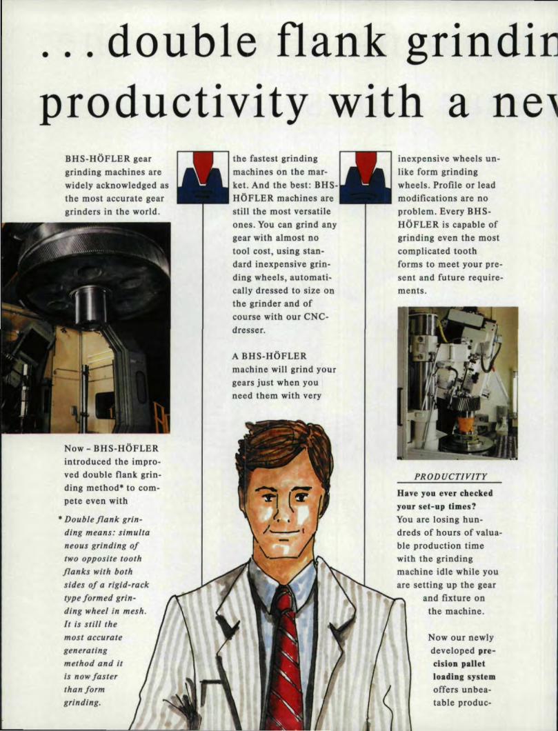
productivity withBHS~HOFLERge.Elrgrinding macbines arewidely acknowledged asthe most accurate geargrinders in rhe world.
the fastest grindingmachine's on the mar-tet. And the best: BHS~HOFLER. machines arestill the most versatileones. You can grind anygear with almost notool cost, usiugstan-dard Inexpensive grin-ding wheels, automati-caHy dressed to size 0'0
the grinder and ofcourse with our CNC-dresser ..
A .BHS-lIOFLER.machine win grind yourgears Just when youneed them with very
Now - BHS-HOFLERintroduced the impro-ved double Hank grin-ding method" to com-pete even with
ain,expensive wheels un-like form grindingwheels. Profile ,or Ieadmodifications are no'problem. Every BHS-HOFLER is capable ofgrioding even the mostcomplicated toothforms, to meet your pre-sent and future require-ments,
PRODUCTIVITY
Have YIOU ,ever checkedY'O'Uf seC.-up Um,es'!'You are losing bun-dreds of hours of valua-ble production timewith the grindingmachine idle while youare setting up' the gear
and fixture OD
the machine.
'"Double flank grin-ding means: stmuttaneous grinding oftwo' oppo.su,e toothflanks with bothsides of a rigid-racktype/ormed grin-ding wheel in mesh.It is stUI themost accutat.generatingme#l'Od ,and itis now lasterthan/armgrjnd.ing.
Now our newlydeveloped pre~dsi.on panet.llOadlng systemoffers unbea-table produc-

30-50 0/0.g:gear grinding system.
tivity! Our pallet setupstations win keep yourgrinders busy. Muchfaster change-ever time ..AU unproductive setuptime is done outsidethe machine where itbelongs while your grin-ders grind gears hourafter hour - uninterrup-ted. Twenty feur hoursa day?' No problem, pal-lets can be Ilned up, forthe 2nd or 3rd shiftoperation.
SUPPORT
To get the maximumproductivity from yourBHS-HOFLER, we nowoffer a training pro-gram for your opera-tors. Experiencedinstructors let youbenefit from their life-long obtained know-how. Our computer pro-gram is available to cal-culate grinding times,machine set-up dataand other valuable para-meters.
Even thee best machinesneed service and partsfrom time to time. OUf
factory-trained serviceengineers are availablefrnm BHS-HOFLERCORP ...,.New Jersey.
In. addition to spareparts we stock grindingwheels and otherperishables in our U.S ...facility.
For more information,can or write toBHS-H'OFLER CORP.P.O.Bo'x 127Sky Manor RoadPittstown,NJ 088,6,7Tel. : 9.08-996-6'9'22Fax: 9.08-99'6-6977
We win be more thanhappy to arrange ademonstration in yourarea at one of our U.S.customers or to orga-nize your trip and visitto BHS-aOFLER inEtUingen, Germany.
You are producing har-dened and ground ge-ars. A product with abright future becausemore and moregearsare ground. But Iike inevery 'competition onlythe best wlll survive,The gear grinding ope-ration in your companyis probably the mostimportant one becausethis is where your namegoes on your product..BHS-HOFLER state ofthe art gear gri.ndingmachines send signalsto your customers thatyour company is a lea-der in its field becauseyou are capable of pro-ducing the highest qua-lity products, Get tbebest, contact us and wewin put you in the com-pany of the most suc-cessful gear manufactu-rers in the world, Let'sdo it together.

·'.BHS-HOFLER salesagents in the USA:
Western States;'
AMERICAN MACH~NERYANn ENGINEERING CORPORATIONP.O.B.2IS7Mission Viejo., CA 92690Tel.: 714-586-2000Ask for Ron Luebke
Indiana, Illinois, Wisconsin. Iowa, Mirm,esota:
JRM & ASSOC., INC.5633 East State StreetReckford, I.L 6Il08Tel.: 815-397-7557Ask for Jim Mattox or Mark Bitaler
New England Stales;'
LYND-FARQUHAR CO.East Point Crossing176 East Main StreetWestborough, Mass. 01581-1706rei.. 508-898-9'494Ask for Howard Rich or Rob Smith
E-Pennsy{vania, New Jersey, Maryland, Carolina,'
HOLCO MNC.8 Lindenwold TerraceAmbler, PA ]9002TeL: 215-283-0156Ask for Emil or Marc Conti
W·Pennsylllania, Michigan, ,ohio, Kentucky, Virginia.:
J. LEE HACKETT COMPANY.23550 Haggerty RoadFarmington, Michigan 48335-2636Tel.: 3B·478~0200Ask fur J ..Lee Juett or John McCartney
BHS·HofIer Mascbinenbau GmbHIndustriestraBe 19 . D-7505 Ettlingen 7 . OermanyTel. 072 43/99' 10· Telex 7829.07Tetefax 072 43 199165CIRCLE A.-1010n READER: REPL'II' CARD

Multi·ThreadRobs With New
I
'.-INyL
AbstlCBct:In spite of dle 'use of high speed steel hob .aad front and hack edges non-uniformly. This is ex-
sta[e~f-tbe-an bobbing machines, increased hob- plained by the fact. that tile cutting edges of teeth, cutbing efficiency is still demanded. However, dus layers of different thickness, Tiley are also ,engag-desire is often cheeked by the corner wear of hobed in at IlOn-freecutting condition. (They are cuttingteeth. Anew method of analyzing the wear "V"-shaped layers when twe cutting edges are ap-mechanism, is proposed. ThemicIe provides the plied to the work and "W"-shaped layers when threeresults ohhe research on the work of hobs with dlf- cutting edges areapplied.) This brings up additionalferentcutting diagrams. It is also presents a new shear stress and compression stress, whioh depends,cutting diagram which makes itpessible to decrease chiefly on the angle (C~ of chipflow, which Liesiii b wear two to four times and the cutting foroe by between the perpendicular to the corresponding20% to 40% . cutting edge and the direction of the chip flow. The
greater the angle, the greater the value of additionaldeformation of 'the layers being cut. In the mostIntrodurtion.
During the last 20 years 3 great amount of simplified form it is possible to' describe the toothresearch has been dedicated to' the problem .of in-creasing production efficiency jn hobbing. Amongthe most efficient methods developed are the use ofmulti-thread hobs with optimized cutting oonditionsand diagrams and die search for a !'leW method efgear cutting.
wear of a hob as:
1ih· "" AI a·l[l +A·. Iw. tg (C)']dLI I ,I I. , I,
o Ii
where aj = thiclmess of the cu.t.layer., mm;~l = distance of cutting. mm;
1w "" distance of cutting on which th--bobNew Analysis of BobbingThis article demonstrates a new mel110d 'of
anal.yzing the hob wear mechanism. Research onhob wear reveals that hob teeth are worn out on
,edge cuts complex "V" or '''W'shape layers, mm;
Ai> Ai = constants"
DR. N. :SMIIRNOVj, head oJlht General
,(1) Subject Department andDean of the Faculty atVolgograd P:oly/fchnicalInstitute, Yolgograd,USSR. He has publishedover 40 articles andreceived nlnt pall'flU ill
tilt fitld of hobbing cmd ispresently a I'isitingpraftssor at MichiganStat« Universlty.
JULVIAUGUS,T at. 27

EE.. 0.6'"a,),
~E:l 0.4.5><«I:;
h.mm
0.8
0.2
o2 3 4 5
Blade number
Hob: m = 4. 25. PA 200, 3 RH. D = 120 rnrn, N = 12.
P9Kto;Gear: HA 0°, Z = 48. b = 50. st. 40X;Cut. Cond.: F = 2mm/rev., Con venti ona.h "'{=~4mlmin., T = 80 min. [-top; 2-lefl; 3¥rigl:n; 1,2,,3-experiment; 1, 2, 3 - calculated.
28 GEAR TECHNOLOGY
Fig. ~. Comparison of wear between experiment and (hal:predicted by Modell
Tile angle of chip flow was determined fromindependence of action of forces. For the [01'edge:
C1 =arcig
bl 3 bj
lal'db, +1: [Sin(ai)'jaj'dbj]
10 i=2 10(2)
where 112 is 1l1einJet.leading profile angle. and Ilj
is the outlet nailing profiJe angle of the side cuttingedge of the hob.
The cutting thickness (ai) and the width of cut(!bJ of each hob tooth, as wei] as length Oil and Ow)can be calculated. (J) In order to know Ai and A iwemust. make experiments, in which the factors in-fluencing the wear ofthc hob must be equal to themiddle of their modified area, For example, if thearea of feed is [-3 m_ml rev, module 2-4 mm.thenthe modified conditions of hobbing are f= 2mml revand m=3mm. Fig, Willu trates wear on hob.
It is clear from Formula I that hob (too]) wear canbe decreased! by dividing complex "V" and "W"
shapedlayers into elementary ones; that is, it ispes ible to divide complex cut layers into elernen-tary ones by means of cutting diagrams introduc-ed by Prof. S,N. Medvedichkov. Medvedichkovhas found that in order to avoid the interference ofthe chips gathering from the top and both sides, thetooth profiles must be modified as shown in Fig. 2(bJ. Nabs wilhlhis diagram, are called'''pro-gressive" ..One profile is standard (low tootn-2, 4,6, ., .,), and another is higher bya value of,el. andis reduced in tooth tltickn - '. (is narrower by ~).
It is obvious from Fig. 2b that the lOp chip flowand the side flows do not interact at all. Medved-ichkov has found that values eland ~ should beequal.tolhe maximum thickness of layers cut by topal and exit 32 edges ofthe tooth, which engaged incutting first. High teeth of progres ive hobs getworn to a greater extent. Their wear is 2 to 3 timeshighertl:tan that the wear oflow teeth; however. thetotal wear of Medvedichkov's progressive hob(Fig.2b) is 2 to 3 limes les than that of a standardhob (F.ig. 2a).0) Ueno, Terashima, and Hida.ka(41arrive at the same con elusion inllteir study of asimilar situation.
The use of Medvedidl};:Ov's progr-essive bobscuts down tool wear 2 [0 3 times and enning stress20% to 40% . On the other hand, the use of the bobsincreases the error of involute tooth profile . Theauthors hob reduces this error. (See Fig. 3.)
Bobs with NewCutring Di~grams,Hobs with new diagrams (Fig. 3a) differ from
standard ones (Fi.g. 2a) by alternation of the stan-dard UXJ!h with protuberance with ones that arehigher by a value of e I. and narrower by a.value of,e:! and have no protuberance. (SI Hobs without pro-tube:ranoe, but wilh the same cutting diag;ram. areshown in Fig, 3b. Cutt:ing,edges of high teeth are:edges ~-2; 5-6; 9-10. Standard teeth work wilfledges I-2-3-4 and 7-8-9-10. [1'1 that.case the errorof generating involute tooth profiles by a standard(Fig ..2a) 110band by new ones (Fig. 3) are identical.
Besides, the author proposes to choosee- and ~so '!hat the wear of"higJ1~and "low" teethare 'equal,which decreases the wear of new type hobs by 1..5to 2,0 times compared to Medvedichkov's hoh . [1'1
this case the values el and ~ are determined as:
el =a] - [all] +0.5[11] . 19ii:] .}..I (3)
~=a2+ 0.5[b]· tgii:2
where [1'1] is allowed (extreme) value of hob wear

in m:m, and a! and a2 are back clearance anglesof top and side cutting edges. Values 31 and 32 inthe prevented formula are equal to maximumthickness oflayers cut by me top and inlet (leading)side cutting edges of the most worn tooth.
After calculating ira,] through Eq .. (1) whenhi.=112•value el can, be obtained through Eq, (3).Such c..alculationofe! and 62ha been done. but itis very complicated. In order to prove the calcula-tion,a lot of experiments were made. Table 1shows the experimental zones.The experimental and calculated data are similar,but for determing values e Iand ~ it is better to useformula:
10 7 ( . ,0.7(t)0.6( -) -O.4( _)0.7(~. \ -0.9 +el =' '.. nlV· . ,. z' ··m'· ~O.5·[h)·tg(a'I) , (4)e2 = 1.1.(nJo;8(f)0;4(z) -~.4(m)~·6(ziJ -0.9 +0 ..5' [h]·tg(a2}'
Standard Profile
Standard Tooth2; 4; 6;
1!!g~I; 3; 5;
~.
b)
Fig. 2. - Standard (a) and progressive (b) hobs,
Table 1 - Experimental ZonesZone
Dimension "from" "to"
Hob:Module (m), m:mNumber of thread (nJ'Number of gashes (ZJJGear:Number ofteeth (z)Cutting condition:Feed (0.,. mrn/rev
"unloaded! of unifonn wear," and tile hobs of tileMedv·edichkQv diagram (Fig. 2.b) with values ,eland 62 determined by Eq. (4) were called "pro-gre siveof uniform wear." Fig. 4 shows the in-fluence of'value elan the wear ef such hob . Thisfunction can be divided into four zones. Inlfle firstzone the value of e1 is very small and the standard
Hobs with new diagrams (Fig. 3) and equal wear "low" toejh, engaged in non-free cuning condition,of "high" and "low" (standard) teeth were called has limited wear (Fig. 4, line 1). When el = e'l>
the wear of"hi.gh"and "low" teeth becomes equal.The "Low" tooth cut "V"-shaped and "W"-shapedlayers until el<ej(Zones Wand2). n is clear fromFig. 4 that value [ad in Eq,. 3 is [al] = ej - e'~ InZone 3 "Jaw" teeth cut elemeruary layers, and thewear Qflhe "high" toolh is 2-3 times higherjhanjhewear Qfdle "IQw" tooth; however. m·· total wear ofsuch hobs is 2-3 times less than that of a standardhob (Fig. 5). Further increasing of el. led.to unfor-tunate results: the wear oftbe high tooth increased(Fi.g. 4: Zone 4). Such increasing of wear dependson deterioration of the cutting condition: the hightooth in such a case (rather like need Ie) engaged inclltti:ng "V" shaped layers.
Now we can make a very important conclusion:modLfyLngthicknessofIayers cut by the top cutting,edge has influence on corner wear on side cutti..ng,edges. This facl corroborates the author's eonclu-sion that the wear of hobs depends on flow chipangle c, (Eqs. 1 and 2).
Fig. 5 shows the influence of cuJting diagrams onthe wear of'habs. Tests showed. that the best wearresistance was obtained by use of hobs with pro-gressive and "unloaded" cutting diagrams withuniform wear. (See Fig, 5,) Their wear resistanceis 2-3 times higher than that of conventional hob .
To determine the efficiency of'multi-thread hobs
2.5 5.0-5
W 18
[8 60
1.0 4.0.
JULY/AUGUST 1111 ,291

HighToolh
I; 3; 5;
StandaJd Tooth2;4;
a)
Fig. J - Hob with new "unl.oaded" diagram with protuberance Calwithout protuberance (b).
High Tootlle
2
11,rn:m
'.. 0.8(';I;GJ·~~. 0'.6E~::e 0.4
I.; 3; 5;
Standard Tooth2; 4;
b)
wilh new cutting diagrams with respect to' the stan-dard hobs, wide rests were carried mil (Table 2)which revealed that jhe subsdmtienof standard cul- ·{ml~I(f)[O.S8+0.1 S·In(Z)-O. 34-!n("\J1, rom (5)
ting diagrams by progressive or unloaded .0"uniform wear increased the tool life of multi-threathobs 2 • 3 times.
Experiments were carried out on me basis of themulti-factor method. Values of'factors (Xi)1 varyon two levels: xl = + I and Xi = -1 (fable 2).,'Ill ...idataanalvsi th ;;:11' I' ·(m)o'~(f) ...[O.26+0.IS·In(Z)-0.l4'1l1("\J], mmII rougnc 'i:1Jl4JYSlS,' e ,.0 owing re allons werereceived for calculation of hob wear:
standard hob (conventionalhobbing)
0.2
,
] 2 3 4 ~\.
-I
\ II I .,·.0'1[.a ]
!tr... ~p''~ c l,,c .'10r-O""
>'-d""p.-'" ""'~
..... 1 ~,.JM,ej"
o 0.2el' 0'.3 e
l"O.4
Valae e., mm
0.5 ,el,mm0.1
Hob: m = 3.5 rnm: n = 3" FA 20'°·- - t h' ' - Ii
Gear: z = 24: st. 40x: b = 50:
Cut. cond.: V = 54 rn/min; Conventional.
fig. 4 - The influence of value 1:1 on the wear of high (2) and standard (I) tooth •
.30' ClIO'" R T ECHNOLOG,y
unloaded and progressive of uniform wear hob(conventional bobbing)
h=A' '(Vc -)1.90( .. \0.70(1)-.--0.73( )-0.41-2 'RhJ' ·z··
(6)
where Aland A2are constants dependent on thetype of the material under process. For example, ifhob material is P9KlOand material of gears st.4OX, then AI ==5.1 W-6• A2=7.0 10.(6)
Operating capacity of hobs is characterized notonly by their too] life, but also by the cutting forceappearing during operation as well. Therefore,dynamic research ofthe work of rnulti-tbreadhobswas carried out. Both the cutting force and cuttingItemperature were silmultaniously measured. In thecourse of the experiment, it was found that the pro-cess of tighmes, of chip formational simuhaneeuswork of three cutting edges (non-free cutting con-dition) effects not only tile too] life ofhobs, but alsothe cutting force and temperature,
The multi-factor experinent (Table 2) determin-ed the function between the cutting force and elM-ferent factors,
The cutting forces fer conventional hobbiJIg are:
standard hob
P -B·.-or)-O.l7(OO.78( )o.ss(")" L4Q( .)0.181.1'tW!- - 1 \ T • .•. ,. IiIb" mi' Z

progressive of uniform. wear hob
h.mm1.01
(8)0.8..sss;.
E '0.6::I
.5~~ 0.4
unloaded of uniform wear hob
0.2The application 'of new cutting diagrams
decreases the cutting force by 20%40% whichpositi.vely effects on 8VCuraCYof gears,
oTlmm
30 901 ]20 18015060
Time Life of HobColl£lusiollSSummarizing dte above results. the following
eonclusions can be drawn:(1) The relationship between hob/wear and chip
flow for bobbing is obtained.(2) Proposals were made for hobs with new cut-
ling diagrams: unloaded unifonn wear and pro-gressive unjform wear were suggested.
(3) The experiments are carried out on the basisof the tmdti-factor method and the experimentalrelationsare obtained for calculation of hob wearand cutting f0110e when hobsw:ith different cuttingdiagrams are 011 work.
(4) The application of new cutting diagrams cutsdown hob wear 2-4 times and cutting force by20%-40%.
Hob: m = 4, 25 mm; PA 20°; nh
= 3Gear: z = 24; st. 4Q1X; b = .501CUI..Cond.: f= 1, Omm/rev: V= S4m/min:Conventional Cutting Diagram: Standard (1)Medvedichk:ov's progressive ,(2)Unloaded of uniform wear (3)Progressive of uniform wear (4):
Fig. 5 - The influence of cutting diagram on the wear of the hob.
In conclusion. it should be stated that employ-ment. of multi-thread hobs with progressive andunloaded cutting diagrams of uniform wear resultin, an increase in hobbilng efficiency.
Aelmowkdgemen_: Our ~ t!'l' Mr, Yejim KOIlyarofAlrlLriCtlll Pfauter Umiltd I'arrnuship for his Mip wilh 1MU'chnicaJ ,editing of this article.
Table 1 - Matrices 'of experiments(values nf fadors)
II Factor
Reffllell.oes:1. TERASHlMA. K. UENO, T. "Numericall Analys.is
of Hobbing in Unfinished Space.,"Bul. JSME. Vol.21. No .. 155, p.'907.
2. MEDVEDlCHKOV, S.N.Patent of the U.S.S.R.No 167118, 1%3.
3. MEDVEDlCHKOV, S.N. "Mobs with New Cut-ting Diagrams", .Progressive Curfillg in MachineBuilding, Mosoow. Nauka, 1966.
4. HENO, T., TERASHlMA. K., H1DAKA, K. "On,the Comer Wear of Hob Teeth ," World COllgr.esson Gearing,. Paris, 1977, Vol ..2, p. 991.
5 .. MEDVEDlCHKOV,. S.N., SM[RNOV, N.N. elal. Patent of the U.S.S.R., No. 8912791978.
6. SMIRNOV, N.N. "Influ.enceofCutting Diagramon Cutting Force.in HobbLng",.Progressive Processin Machine Building •.Volgograd, 1985.
Values offactor, Xi;
+1 0 -w75 64 542.0 1.4 LO
2 3
40 28 20
90 63 4548 .34 24
4.25 3.5 2.5
Cutting speed, V,m/minFeed, f, mm/revNumber of thread, nIl
Tooll:ife, T, min standardl'IobProg ..or unloadedNumber of gear teeth, zModule, m, mm
JULY/AUGUST 1·"11 31

Join theWi'nningTeam BOURN & KOCH HAMAl
MODEL 150H CNC BOBBERMaximum Work Diameter---8.0"Maximum Hobbed!Length-12.0"Maximum Hob Diameter=-d.O"
The machines are con trolled by aNwn 760E Gear Hobbing GNG Controllerwhich is specifically designed for gearhobbing and eliminates the need for anElectronic Gear Box.(EGB). Speed, Feed,Helix Angle, Number of Teeth and Hobshift are programmable. AB many as300 part programs can be stored.
Standard Cycles withConversational. Programming'. Single or double cut hobbing• Worm gear hobbing• Automatic hob shift
Purchaserollhe'Barber Colman!Macbine Tooillivision
BOURN & KOCH HAMAlMODEL 60H CNe HOBBERMaxim.um Work Diameter-4.0"Maximum Hobbed Length-6.0"Maximum Hob Diameter-1.875'2500 KISHWAUKEE STREET
RDCKF.DRJ),ll611104815/965~4D13FAX 815/96501001,9
ADVEATOAIA'l
B!EST FliT SOLU]IQNS
Bourn & Koch MachineTool Company, Rockford,Illinois Provides UniqueSolutions to Solve GearManufacturing Problems
Pullhasef of lb.! IB.lrtler Colman IMachine Tooll Division250D IISIIWADIEE S1iRH1i- ROCIFDIUI" D. SHIM- 81~3 • FU 1151965-11019
CIRCLE 1.·12 011 ,READER ,REPLY 'CARD
Problem-a high volume producer of wormwheels for the transportation field presentedBourn .& Koch with a typicaJIJindustry scenario.Multiple hobbing machines. aged. worn, longcycle time" high scrap rate and limited capital,
Analysis of the facts included floor space,labor, production requirements, qualityrequirements, limited capital and a verycompetitive market place. Solving the problemswith existing technology was not a Best FitSolution.
It was determined that a new eonflgurationof a hobber would be the best solution to meetthe customer's needs, Bourn & Keachdesigned!and built an automated seven axis CNC verticalhobbing machine which produced two partssimultaneously ..The Duo-Bobber, with twowork spindle and two bob slides close coupledwith a singl.e polymer concrete base, producedtwo parts every 28 seconds. Silo storage andautomation allowed the Duo-Hobber to operateunattended for one hour.
End result-one Bourn & Koch Best FitSohnion replaced four existing bobbingmachines and met the ,customer'· requirements.
Preblem-a Japanese Aerospace manufac-turer required a precision hobbing machine tobob incone] H8 and maraging steel 250 at 52RC'..The gears and splines to be cut required awork zone of24 inches in diameter and up to[44 inches in length between centers,
A Best Fit Solution was to design a 5·axi.sCNC horizontal. bobbing machine, The 600HCNC Hobber is a precision machine withpolymer concrete ill the base and hob saddle toprovide vibration dampening ebaraeteristiesrequired for carbide hard hobbing.
Bourn & Kochhas been designing andbuilding machine tools requiring exact toleranceswith polymer concrete, cast iron and/or steelcomposite members for morel1!lan ten years.
Application determines the Best Fit Solution.Not every application can be addressed bystandard, universal product lines. Even thoughBourn & Koch has a full line of CNC andmanual hObb:ingand sltaping machines, we letapplication determine configuration.
The 600H CNC Bet Pit Solution is areversal of trends in the machine tool industry'today. exporting equipment to' Japan.

34 GEAR TECHtiOLOGY
Gear FundamentalsR E··everse I,-nglneerlng
Vefim KotlyarAmeric81D Plau!er. Ltd.•Loves Park, IL
IntroductionWhether gear engineers have to replace an
old gear which is worn 01.11, find out what. a gear'sgeometry is after heat treaememdistortion, or justfind out parameters of gears made by a competi-tor. sometime they are challenged with a needto detennine the geometry of unknown gears.Depending on the degree of accuracy required, avariety of techniques are available fordetermin-ing the accuracy of an unknown gear. If a highdegree of precision is important, a gear inspec-tion device has to be used to verify the results.Frequently, several trial-and-error attempts aremade before the result reach the degree ofprecision required.
The concept of the reverse engineeringmethod described below i 'employed by orneCNC gear measuring centers for automatic deter-mination of unknown gear geometry ..This articleis an attempno y ternatize a method for accuratedetermination of unknown gear geometry with orwi thout the use ofCNCinspection machinery andsophisticated oftware.
Concept. and RequtrernentsThe result ofa gear inspection provides
enough tnformation for detenninilng actual geargeometry characteristics. For instance. the resultof .11 gear involute inspection can be used fordetermining the actual base circle diameter (Fig ..O. The actual base circle diameteris a functionof involute error. length of roll relevant to theinvolute error, and the base circle diameter whichwa as umed in order to conduct rhe involuteinspection. Similarly, the re ult of a gear leadin pection provide sufficient data for-calculatingthe actual lead (Fig. 2),_ Thus. by making an
8D - Actual, baSI! ade <lamelerbd' - AAUIed baR ctde' ,cIame'erError - Ikwolule 'errOl" defectedRoll Length - Length of rol rel....O!'1! 10 delectld error
BD • bd M' ( 1i • Error {Roll Length I
"'i~. I
assumption for a gear base circle diameter andlead and using the results ofthe inspection ba edon til is a sumption, it is possible 10 determine tileactual base circle and read of an unknown gear.
Every gear hasa unique base circle diameterand a unique lead. However, the arne gear canhave numerous combinations ofNonnal PressureAngle (NPA), Nonnal Diametral Pitch (NDP),Pttch Diameter (PO), and Helix Angle (HA),because these parameters are relevant to gearmating qualities or cutting tools. Some geardrawings contain va:riou combinations of NPA.NOP, PD. and HA. It i important to realize thatonly base circle and lead are unique and can beverified. The pitch diameter at which the gear i

going to be me hed wi til another gear and related'characteristics like NDP, NP A. and HA can onlybe guessed, since tile same gear can mesh withvarious gears at different pitch diameters.
The main concept of this method is thattheunique gear characteristics like base circle di-ameter and lead are indirectly measured first bytri.all,-and-error technique with a specified degreeof precision. One or several combination ohhere tof the parameters can be computed afterwards.
The task is divided into three teps, The firststep is determiniag gear base circle diameter. Thesecond step is determining lead - required only forhelical gears. The third tep is computing of othercommonly 1.1 edgear characteristics based on thebase circle and lead.
The fir Iand second steps require a lead andinvolute measuring machine with, variable basecircle etting capabilities. IIdoes not have to bea modem CNC gear checker. However. utilizinga CNC gear checker. especially one which canfollow thetooth form material. makes the deter-minalion of a gear's base circle and lead easier,more accurate. and requires fewer iterations.
Step 1 - Determination ofBase Circle Diameter
Repeat Sub- tep 1.~ and 1.2 hown belowuntil the lope error becomes smaller than therequited gea:r accuracy, Generally, the accuracydoes not have to be smaller than one micron(0.00004"). At any rate, it would be uperfluousto use a number which is smaller than the accu-racy limitati n of the inspection machine. Be-cau e of imperfect gear surface conditions andpossible inspection inaccuracies for gears withlarge errors, :i.t is necessary to repeat Sub-stepsI.] and 1.2, using a more and more accuratebase circle diameter for each iteration.
The accuracy of the first assumption is notcritical becau e every following iteration is agiant leap clo er to the actual ba e circle diam-eter. Usually, 110 more than three iterationsshould be requir,ed, regardless of the first as-sumption .. However. the base circle diameterassumption for the first iteration should besmaller or equal to the gear root diameter.Otherwi e, since an involute does not existbelow the ba e diameter, tit might be impossible(0 makean involute inspection.
Sub-step I. J. A sume a gear base circle(PBD) for the first iteration or use the result
is an applications engineer.....ith American Pfauter Ltd.He is responsible forcomputerized aJlaly is ofgear geometry and' geartechnologies. He earned amasters degre« inmechallical,nlg/netTingfrom Ihe .odessa MarineInstitute. OdesSlJ. USSR.
JU~VIAUGUST lUI 35
Face
1-!BO ~. Base c1rdt' clameter""A. - .Aclual leodASL - "au-I(! It<ldFace - Gear face "'leIIllBI'tA - Base helix angleError - Error detected (tyrll"!g teed In.~cllon
TarnBHAI .. PI " IBI), I ASLAa. ~ .ASt. '. (1 .. ErrorllFa<:eM 1~BH"II
I·i~. .:!-- -
L!F!1
Involute ,"-peello", rewll
LR1 - Length '01 roll 101"/nvolYle IPotrd1l.B2- L'eorlgttl 'of toll '01' 1!'!VoIute !)01nt2ER - Evaluatlon rC!flge '.xpr ••• ~: In length 01 roll
ER '. Lf!1 - LR2
tNVOLUT'E INSPECTION
hi.!. J
calculated in Sub-step 1.2 for setting. up an in-spection machine. Inspect the gear involute andrecord slope error (Slope) and evaluation rangefER). 'The evaluation range is the length of roll forwhich slope error is observed (Fig. 3). Mo t Vefim Kotliyairinspection machines provide inspection re ults ina scale proportional "10 the length o:froll, and thisis the unit. system thai should be used, Forin lance, if the base circle diameter and evalua-tion range are in inches, then the slope errorhoul dlbe iiii inches as weill. Depending on whether
a material plus condition i do er to the root or tip

Left flank
Slope
RIgi'1 lIa.nI(
'-il.!. -I-- ---
Toolh tip
ER
Sl~ ,~ nVQIu1e slope errorER ~ 'Evoluallon rctl'!~' expre.. :~ h length of roll
between po'Il1' 1 ond ,2 01 the "vofule
-----
Fig.5
Too", reet
INVOLUTE INSPECTION'POSITIVE SLOPE ERROR
Rlghl 'nonk
st.ope'
Gear· 'face, wldltl
----- ---
~ ilo(. 6
Toof tip
2
'ER
:Slope' - lI'I...oIul'. ~ope errorER ~ iEvaluatlon rCI9 4!lq)I'Msed: In length of foil
belw~Jl pm! 1 and 2 Qf tM Involute
INVOLUTE INSPHTIONNEGATIVE SLOPE ERRQR
Slope - LNd slopo' erl'Ol'ER' - Evctlu:lllon range,
LEAD INSPECTION
36 ClE.iI!,Il TECH'NOLOClV
of [he tooth, the slope error should be positive ornegative, (Figs. 4 and 5)
Sub-step 1.2. Determine a more accuratebase circle diameter.
NED = PBD * (1 + Slope/ER)
Where:Slope = slope 'error recorded during
inspectionER = evaluation. range
PBD = previous base demeterNBD = new base diameter
If the slope emu exceeds the required accu-racy, Sub-steps U and I.2hould be repeatedusing the new base circle diameter (NBD) forsetting up an inspection machine.
Step 2 • Determination €If Lead(This step is not required when dealing with spurgears.)
As in Step I, Sub-steps 2.1, and 2.2 should berepeated until the slope error becomes smallerthenthe required accuracy .
•Sub-step 2'.1. Assume a gear lead (for thefirst iteration) or use the result calculated in Sub-step 2.2 for setting up an inspection machine.Inspectthegear lead and record slope error (Slope)and evaluation range (ER).
The slope error is positiveor negative, de-pending on whether a material plu conditionexists on the inspected flank do er to the top orthe bottom of the gear. (Fig. 6) Also notethatsome in pection machine require a.different signfor lead depending on whetherthe right or lefthand gear is checked,
Sub-Step 22. Determine a more accurate lead.Tan (BHA) = Pi '" BD I PL
NL = PL '" (1 + ( l.opeIER)lfan(BHA»Where: BD;;;;;;Base diameter determined in
the Step IBHA ;;;;;;Base helix angle
ER = Evaluation rangeNL=New leadPL = Previous lead
If the slope error exceeds the required accu-racy. repeat Sub-tep _ 2.1 and 2.2 using a newlead (NL) lor setling up an in pection machine,
Netes for Step land Step 2If the accuracy requirements are very high,
then a more precise filtering out of the surfaceirregularities created by enveloping cuts or feedmark can be beneficial. tn this case theassis-

Tooth rool
Left A.verage • I LeH1 .. L,efl2 .. Left3 .. LeH' ,I I ,RIg'" Averag.e .. ,[ Rlght1 + IRlght2+RJsr!t3 ..Right-' ) 14A.vero,~ Slope Error • [ I.eft Average + RIghi Average ) I Z
INVOLUTE AVEIRAGE SLOPE ERROR-- - ----
"i~.7
Bolfom
Left Average'· ( Left'!. Left2 .. L'efl3 .. Lefl4 ) I ,Righi Average· ,( RIghl1 .. Rlght2 ... RI,ght3, .. Right' l /4Average Slope Error .. ( left Average - Right Average) I 2:
LEAD AVERAGE SLOPE ERRORI·i~. N
tance of a computerized "least square, best fit"slope calculation can be used ..
The undesirable effects of gear run-out,wobble, and raper on the results can be decreased.Involute and lead slope errors can be averaged outby checking right and left flanks as well as severalequally spaced teeth. (Figs. 7 and 8) The result-ing average slope error can then be applied in theSteps ].2 and 2.2. Obviously, this wouldprolongthe inspection time, but would also providemore accurate results.
Since most inspection machines measure leadand involute in the transverse plane (plane of gear
rotation), these formulae are valid for trans-verseplane inspection. If an inspection ma-chine checks a gear in the normal plane, thenthe slope error in the transverse plane could becalculated approximately as follows:
Transverse slope error =Normal slope error/Cos(H!elix Angle)
Another difficulty may be encounteredduring gear inspection. Unless an inspec-tion machine can follow the material, it islikely that the machine win run out of probedeflection range beforecompletion of theprofile or lead inspection. However, one
JULV/AUGUST 199' 3,7

38, GEAR TECHNOLOGY
CaIeulatedJ?ara.m.etersAssumedJ>aramder
PDHelical GearHA == Arc'I'an (Pi * PDJLead)
NDP '" Z/(PD '" Cos(HA»TPA", ArcCos (BD/PD)NPA = Are'Ian (Tan(TPA)
'" Co (HA))BHA", ArcTan (pi*BD/Lead)
Spur GearNDP = Z/PDNPA '" ArcCos
(BD/PD)
PD =BD/Cos (NP'A)
NDP = z/pn
PD=Z/NDPNPA '" ArcCos
(BD/PD)
Tahle 1
HA PO = Lead'" Tan(HA)/PiNDP = Z (PD '" Cos(HA»TPA == ArcCos (BD/PD)NPA = ArcTan (Tan(TPA) '"
Cos(HA»BHA = ArcTan (Pi * BD/Lead)
NPA BHA = ArcTan (PI'" BD/Lead)HA = ArcSin (Sin(BHA)/Cos(NPA)PD::; Lead > Tan (HA)/Pi
TPA '" ArcCos (BD/PO)NOP = Z I (PD * Cos(HA»
NOP BHA = Arc'I'an (Pi'" BD/Lead}HA= ArcSin (Z *' Tan(BHA)
(BD'" DP»PD = Lead * Tan(HA)/Pi
TPA '" ArcCos (BO/PD)NPA =: Are'Tan (Tan(TPA)
'" Cos(HA»
Where: BO '" Base Diameter determined inthe Step I
BHA = Base Helix AngJeHA= Helix Angle
Lead = Gear Lead determined in theStep 2
PA = Normal Pressure AnglePO '" Pitch Diameter
Pi = 3.]41592654TPA = Transverse Pressure Angle
Z = Number of teeth
(HA), and pitch diameter (PD) can be calcu- factored imperfectly. If measuring machinelated, Since the same gear can have numerouscombinations of these characteristics. one ofthem should be assumed in order to calculatethe rest. Depending on whether pitch diam-eter, helix angle, normal pressure angle, ornormal diarnetral pitch is assumed, one of thesets of formulae shown in Table ] could beused in order to calculate other traditional gearcharacteristics.
ConclusionsThe described technique assures accurate
determination of a gear's actual base circle di-arneter and lead. evertheless, the result mightslightly differ from the base circle and leadspecified on the print because gears are manu-
inaccuracy is disregarded, the difference be-tween the actual base circle and lead and adrawing specifications depends on how accu-rately the gear was manufactured.
It is also important to reiterate that variouscombinations of aonnal diametral pitch (NDP),normal pressure angle (NPA), helix angle (HA),and pitch diameter (PD) can be specified for thesame gear. Thus, depending on need, selection ofproper assumptions in Step 3 is important. Sup-pose one needs to reprod uce an unknown gear andhe has a stock of 20° pressure angle hobs .. In sucha case, it is rea enable in Step 3 to make anassumption for normal pressure angle of 20° andthen calculate the rest, hoping that one of theavailable hobs could be utilized.

I[R]HDI'
NCNlYOU can see !hedifference in expansionarbors and chucks. Eliminatelosses and rJc.vn time caused byaccidental actuation or leakini sealsthat effect products of lesser Quality.HD T manutactures a .superiorself-contained hydraulic work holdln&"loo/holdini system designed for your needs.DON'T SETTlE FOR LESS THAN HOT -COMf1l.Rf OUR FEATURES
We'll Change The Way You View The Gearing World ...
GEAR EXP,O' '91"'The Wodd of 'Gearing"
Detroit, Michigan.October 20 - 23" 199'1
'.,AGMA's GEAR EXPO presentsthe .Iatest indesign and manufac·turing tecbniques to an audienceequipped. wUh purcbastngpowel"!
,.,GEAR EXPO is, b~gg,erthan ever,with a.68% increase in booth space'overthe'89 show. Past eXhibitorsare eJqmD.ding this yeaJDnd bIi~·ing beavier machinery onto theDoor. This show ,is! alrea4y large,.than last year's!
I' (1:you supply ,the gear ,iruIustry" youshould be in Delroil, 'CkWber 20 -23, 1991. COBO Co,n/erena andExhiIJitio.nCelller:.CIRCL'E A.;f 5: on READE R REPLY :CARD
p----------------------. IIIIII
Yes!: lam Interested in ,attending or exhibitiingat GEAR EXPO ,.;0 Please send me more inrormation on ,attending 'GEAR EXPO.ICJ Please send me more information on ,exhibiting at GF..AREXPO.
Name/,Company
t\dd.ress
City,. State, Zip
'T'elephone # (include area code)
Please send this ,oouponto: kG MA. Headquarters, lSOOKing Street,I Suite .201,Alexa~driaJ VA 22314 or con 703/684 .•0211 by October 1.._--------------------_.
JULY/AUGUST' 1991 ,39

OPT,'ONALEQUIPMENT
FLEXIBL.ESYSTE'MI
STANDARDUN,IT
ADDIT,IO~L. OPTIONS
* Dust Conectors* CN'C Controls* Autoload/unl'oad
,FEATURIES
* Options Ilnstal'l and ,Removein Seconds
* Multiple Operations inOne Cycle
* 10/00 De,burning
James Engineering· 11707 M'cBeanDr.· EI Monte, CA 91732· 11'81'8),442-2898. Fax 18181442-0374
CI ROLE A·140n READER REPLY CARD'-
ADVERTIS,ER INDEXPage Reader Service Page Reader Service
Number Number Number Number
AGMA 11 A-38 Intercontinental Industries, Inc. 42 A·16
AGMA 39 A-15 James Engineering 40 A-I4
Amarillo Gear Company 43 A-18 Klingelnberg Gear Technology, Inc. 47 A-3
American Metal Treating Co. 44 A-20 M & M Precision Systems 6 A-6
American Oerlikon 5&44 A-5 & A-19 Manufactured Gear & Gage. lnc, 45 A-23
American Pfauter, Ltd. Cover 2 A-I Mitsubishi Heavy Industries, Ltd. Cover 4 A-33
Axicon Gear Company 45 A·24 NASA - Lewis Research Center 46 A-28
BHS-Hof1er Maschinebau GMBH 23-26 A-10 Niagara Gear 46 A-27
I Bourn. & Koch Machine Tool Co. 32 A·II Normae, Inc. Cover 3 A-32
Fairlane Gear 8 A-'9 Packer Engineering 45 A-25
Fellows Corporation 46 A-7 Pfauter-Maag Cutting Tools A-2
Gold Star Coatings, Inc, 4 A-4 Pro-Gear Company, Inc. M A-21
Guehring Automation, Inc. 39 A·13 Profile Engineering, Inc. 44 A-22
High Noon 43 A·I7 Reef-Baker Corporation II A-8
HotlertIMT Div. of Carl Zeiss, Inc. 2 A-30 Van Gerpen Reece Engineering 45 A-26
,40 GEAR TECHNO.lOGY

Pineapples, Corncobs &Other Hobbing Matters
Question: I have worked in thegear manufacturing departmentfor over 15 years, and just re-cently someone told me about apineapple hob. I wonder just whatkind of tool this lisand what it does.
"Pineapple hob" is the rather pictur-esque name the shop people have givento whatreally should be called a tapered-end, tangential-feed, wonn gear hob. Itis used to produce throated wonn gearsona bobber equipped with a pecial feedslide which moves the hob tangentiallyto the gear, ratherthan in tile usual axialfeed motion. Standing on its big end,this multiple-start, high-lead-angle hobwith its helical flutes and long slowtaper, immediately reminds one of apineapple .. Hence, the name.
A lot of the names given to hobs,such as gear hob, involute spline hob.parallel key spline hob, herringbonegear hob, cam haft hob. ring gearhob, ratchet hob, or skiving hob, areproperly indicative of their purposeand use. But many have other pictori-ally descriptive second names. For ex-ample, the term "pancake hob" usuallymeans any narrow-faced hob where thewidth i. much Lessthan the diameter. Acamshaft hob, which is used to' cut theintegral gear on an engine camshaft, canalso be called a pancake hob.
What about a fly cutter? Itis a toolused on a tangential feed hobber to cut orfly-out wonn gear teeth. Basically, it isa hob with all but one tooth removed.Usually this cutter is composed of a
William L Janninck
body with an adjustable blade clampedin place. ]f it is multiple-start and hasonly one tooth left per start, it may alsobe called a pancake hob. If (he hob hasfive or six starts and, thus, has only fiveor six teeth or points, it may be caned astar hob. An earlier name for carbide-tipped fly cutters with only one tooth isthe snail back cutter. an allusion to thetong. rounded-off tooth used to back upthe carbide.
The tapered end hob. the taperedhob, and the tapered root hob have simi-lar names, but. very different functions.The first is a hob witha short, taperedend used to cut helical gears. This fea-ture is used to spread the chip load overa broadened area to reduce the danger ofhob tooth overload. wear, and failure.The next is a hob tapered over its entireform and used on a hobber with obliqueor diagonal feed capability to cut ta-pered forms. such as tapered serrationsor splines. A tapered root hob has iii
tapered outside diameter, but the formitself is not tapered. It is used on anoblique hobber to generate parallel orinvolute splines where the root of thespline is conical instead of cylindrical.
"Corncob hob" is another coinedname for extra long, but rather smalldiameter gear hobs, These were devel-oped as part of a plan to increase gearproductivity in high-speed hobbingby increasing hob rotational and in-dexing speed and by having a longuseable hob face for long in-machinetime. They are usually coated withbright yellow titanium nitride. A quick
"Sho'p Floor" is YOUir collumn.When you have questions youca n't answer or need informationyou can't seem to find, let ourpanell of expens help. They hav'ea total of more thain120 years ofgearing experience. AddressYOUir questions to, them, care ofShop F1oor,'GearTechnology, P.O.!Bo.x 1426, Elk Grove ViUage,. IL60009', orcaU our editoriial staff at(7oa) 437-6604.
William L J'anninc'kis a consultant for nw-illinois Tools. a division oflllinois Tool Works. Inc.lle has nearly 40 years'experience ill engineeringand manufacturing, He is amember of AGMA andASME and is rile author ofmany articles on 100/
applications. gaging. geardesign, and gear inspection.
J U l VI" U GUS T 199' 411

. . #GSa-2t-!S,MODEl. S' capacIty. Gear snaper
- 12 ShapershoOse frorn
ic c 98",s"ro. esl
Lowest pnc ispecial orders;
Sest service.call for
rm",6 afrapin your area
CIRCllE A-16 on REAIDEFI REPLY CARD
42 (lEAR TECHNOLOGY
- - --------------------------............,
glance immediately reveals the corn-cob connection.
Some hob names, such as "convo-lute hob", are not exactly descriptive.This .name is applied to II single convo-lution hob that is used for cutting facegears and face-serrated couplings.
The thread hob and rack hob are nothobs at all, but are form milling. non-generating cutters used for machiningscrew threads or rack gear segments ..Their names are derived from their ap-pearance. From a shan distance theylook just like gear hobs ..
Ouestion: When setting up a gearhobbi ng machine. we on the shop, noorare told to be sure to set the hob swivel,angle as exactly as we can. Does thissetting really have to be so precise?Wha,t happens if it is ort"a bit, saysome 15 or 20 mlnutesj Wearesurewe have run some hobs that were offon this setting, and we never seemedto have any subsequent prob'lems.
The answer depends on whetheryou're cutting cylindrical gearsor worm gears.
Cylindrical gears are much morecommon. These can be separated intotwo discrete types, spur and helical.
The hobs for gears will have a leadangle marked on the hub end or body forset-up purposes. When cutting a spurgear, the hob swivel is set to this angle,so the thread ofthe hob will line up witht.hegear tooth normal section. On a spurgear the teeth are parallel to the gearaxis. On many manual machines, thebest one can set the machine is plus Of
minus about five minutes, based on avernierscale, Of course, on occasion thetrue zero setting on the machine shouldbe verified for alignmeru by use of mas-ter arbors and swingmdicators.
Regardless of the accuracy of thesetting angle. the hob still. performswen asa cutting tool, properly form-ing chips and producing gear teeth.Adjusting the swing angle will not
change the profile produced; the in-volute cut will be correct even withanincorrect selling angle.
To prove this, we conducted tests,supported by mathematical computeranalysis. using a 4DP 20 PA Class Ahob, where we cut five test gears usingthe same hob. The hob swivel was firstset at the proper angle, and a gear cut.and then offset by I -degree intervalsup to 4-degree swivel angle error.All five gears checked correctly on theinvolute produced, with the exceptionthatthe fillet radius became larger as.theset error went up, and the radius La theinvolute starting point also went up.Since we maintained the center distancebetween hob and gears (that is, we kepta constant gear root diameter) we foundthat the hob swept out a wider space andreduced t.hegear tooth thickness by .005inches per one degree of swivel. settingerror. Backwards interpolation impliesthat a swivel setting error of five to tenminutes in general is sufficiently close.
When considering the cutting of he-licalgears, the same results apply. How-ever, the correct swivel angle for like-hand hobsand gears is the gear helixminus the hob lead angle. But one mustbe careful if a short lead hob is used,since in this circumstance, the hobsetting is the helix at the generatingcircle minus the hob lead angle. Sinceshort lead hobs areusually single-pur-pose, the hob lead angle as well as theproper swivel setting angle are bothmarked all the hob.
On occasion a slight swivel angleadjustment is used on purpose to make ahob cut a slightly wider space than thehob was designed for and yet hold theover-pin measurement and root diam-eter relative.
When considering the cuttingof throated worm gears, the swivel settingangle is of much higher importance, andthis i especially so on the higher leadangle jobs, heavily loaded drives, orprecision sets. Typical.ly these sets willuse hobs with smaller oversize, and the

less the oversize. the more ensitlve thesetting angle. However. most single-start sets tolerate more oversize and areless sensitive than multiple starts. Onmany ofthe sensitive sets. five minuteof accuracy in the set angle may beinsufficient, and a pin-and-dial indica-tor may be lied to makepositive smalladju tments. Although a correct zeropoint is not necessary. because you canmake move. relative to the last position.a correct zero point is recommended.On worm gear • where the contactpattern and the gear set axis angle ismeasured on a . epa rate inspectionmachine. the information is fed back10 the gear :holi>ber as man wiveladjustment ui.ng the dial indicator.
, orne time ago ..we were assigned to
design thehobs necessary fora newstyle of very simple pur gear habber.Be ide cutting only spurs and moderatepitches, it was to have no hob swivel,and the table was to be fixedat a..zeroangle, thereby eliminating all the extra.componentsmvol ved. This complicateddesign procedure for the hob was re-quired in order that a zero : et anglewouldbe maintained. WewereslJcces -ful an the tooling for a few parts whichwere te ted, but the inability to designtoolsto meet certain other part specifi-cations caused the project to bestopped .•For more information about this col-umn. circle Reader Service No. 35.
* BRIDLES* B KlES* CLOTHING* BITS* BOOK
*BHTS* BOLOS* CHAPS* SP .RS* ADDLE·
HIGH NOIONWestern C'olJ,ectibles
(213) 202-9010 by appointmen: onf}'
(213) 202-/J40 (fax)'
CIRCLE A-17.0n READER R£PL Y CARD
~CLAY BARBEESales Manager13-year Employee
tiED VAROEllGear Foreman18-year Employee
GLEN McCAINChief Engineer.24-year Employee
I~ •• a'nd we take it pers1o,n'al'yl"We take it personallv when you 'buy a set of spiral bevel ,gears from
Amarillo, Gear-Company.
IFor more' than 35 vears., we've 'been attaching our name to, .quality spiralbevel geal'S up,to 1'00 inches in diameter for clients across the
globe. We've built a reputation for supplying: custom designedspiral bevel gear sets, manu-facturedfor quiet operation anddurability to suit the exact pro-
duction requirements of our• customers.
That's why, from the engi-neers who custom designthe gears to the craftsmen
who manutacture them tothe sales engineer who ser-
vices your order, you'iII see .a.tE~~~I11I11.--:pel'Sona'l commitment to g.ettingit right and on time.
AMIARILLC-
IGEAR COMPANY806 / 622-1273 POBOX 1789. AMARILLO. TEXAS 79105
TWX 910·898·4128 AMADRIVEFAX 806 I 622·3258
-------- - --
CIRCLE .A-18 on REA:DER REPLY ·CARD
JUL'I'/AUGUST III, 43
--- -
CLASSIFIEDSERVICE
COMPL'-'IE FACIO.RY AUIHO:RIZED SERVIICE AND, IPARTS.O:R A'LL,
MAA&ZUIRICIH!
!EQ'UIPMENII
o THE ONLY FACTORY TRAINED AND CERTIFIED MAINTENANCE PERSONNEL IN AMERICA.
e THE ONLY FACTORY (O ..E.M.) LliCENSED PARTS DISTRIIBUTOR liN AMER.I'CAe RECALliBRATION ANiD CERTifiCATION OF MEASURIING DEVICES.,0 COMPETITIVE RATES.
CA'LL(7U8) ,8·10~OO50 iFAX(708) 8110·98·99
5021 ChaseAvenue. Downers, Grove, IL60515CIRCLE A·'·9' on READER REPLY ·CARD
IContlou:r InductilolnHa,rdening SpeciaUsts:
Spur, h.IIC11I,ndben/.flfJars
Our gear hardening equipmentIncludes 4 N'ATCOsubmergedprocess mactunes aM3 AJAXeNG-controlled gear scanningmachines. We can also tool tomest any prOduction need. Writ.e·lor alree bsoch ure,
American ,Metall T,raaUng Company1043 lEast S2ndl StreetCleveland,. OHI441 03
(216)431-4492Fax: (2116)431-1.508
emel'E A·20 on READER REPLY CARD
44 GEAR TECHNOLOGY
'GEAR T-OOTHGRINDING SERV;ICES
• Production and Prototype .Quantities• SpeciaJists in Gear Tooth Grinding• Able to match defivery to your needs• Gear Tooth Grinding Capacity to 27..5
inch pitch diameters.• All services to, AGMA. standards
CERTIFIED GEAR INSP!ECTION
PRO·GEAR COMPA:N,Y, INC.23 Dick Road
Depew. NY 1:4043Phone (716) 684·3811fax (716) 684-77117
Sales Reps. Wanted
CIRlCE A·21 on !READER REPLY C~RD
GEAFilIMANUFA.C1UFiI,liNGIENGINIEERIN'G SE,RV,ICES
,Fenows lModel 'GearlMeasurlng Instruments
• Factory Hebuilding,. Retrofitting/Design Updates
• EngineeringlTechnical Support, Field Service Including
Gear Shaping Equipment
Experienced & Accommodatingl
Aircraft Quality Instruments
Certification to Mil-Standards
~t~~too~lver Street4I.'J~~~ Springfield, VT 05156
IPhone (802) 885·9176 Fax (802)885-3745
CIRCllE A·22 on. READER REPLY CARD

-
SERVICE- - -- --
GiEAR I'NS~PE.CTIONLet us s_olve your gear inspection prob·lems. Repair" rebuild, or update yourIpresent i,nstrumentslo _ne\¥.!99'1 d~sjgns.We can Improve your gear Inspect!on ca-lpabilities. _.
We have design and manufac1urillQ ex,pe-rienealn all gear inspection areas. With,factory trained personnel, we certify, re-pair ,and rebuild Ulinais and Fellows, lead,l'mva'iute tootttspaC8,Bndi gear charters.('Combined: Over 100 y,ears.,e:Kperience.)
We believe' in promptse rvice and reason-able prices lor our customers. Let usmake' your gear inspection instruments,and chart recorders perform like, new.
Manllfacturedl Gear & Gagep.o. Box 7155EJJjln, UHl10ls 60,121
'(7,IJ8) 74'1-24101 or(7,00) 371-2496
CI RCl'E A·23 en RE.ADER IREP!-'II' CARD
,GEAR TIESTING ANDDESIGN FACILITIES,
,GEAR' INOISE ELIMINATEDWHILE TORQUE
CAPAaTY IS INCREASEDThe century-old probIem, of gea ,noisehasftllally been soIv9cIl Wrtfl tfieaid ofan ingenious, new concept andllhelpowerful new tool ,01 compUter sLrrru'l&-lioll', involute' gearing: can now' be 'd~signedthaJ Is not only quiet at BlJIoadSand alJsp8fJd~. but also Ihas iiisubstantially h.lgher torque ,capacitythan conwntiQnal !nvoIutegearing. Aliilredesigns guacanteedl Write or,cau fordetails and/or cpJotation.
,ADIan ... ComiIInvi11':(1. Box 9122 .
Bed<eley, CA 94709(415) 843-8300
I.GEA~RDE:SIGN (NOISE - STRENG,TH~
I
'. RO.TAl1.NG G.EAR ,(TO.R.QUE -. SPEEDCONTROLJ' 11ESl M_ACHINES.
• SINGLE TOOTH BENDING, FATIGUETESTING.
.' STATISl1CAL PLANNING - ANALYSIS.
.' WROUGHT STEELS, SINTIEAEDMETALS, NON~METALLIC MAn.S.
.' CAO FACILITIES ,FOR LOW COSTSET·UP.
• CUSTOM TEST MACHINE DESIGN'.• EXPERIENCED PERSONNEL.
PACKEFlIENGI,NEERING7081505-5722. ext. Z14
IBOX 353" NA'PERVILLE, IL 60566
CIRCLE A·24 on REA.DER IREP,l Y CA.RD CIRCLE A·25 on R.E.A.DERREPLY CARD'
HELP WANTED
[IT Rese!m:h Institute (]ITRI) is a nationally recognizedcontract research and development organization since 1936.lITRl has been awarded IIeontract fr~mthe Defense Logistics.Agencyto establish and operate lin instrumented factory (]NFACl far the manu-facturing afprecisian gelll'S used in DoD appliC!ltiollS. Several demonstrationcycles ofthe precision gearswill be conducted. Engi neeri.ngposition.sare availablefor experienced professionals with advanced degrees in related teclmlcalareaa
PROGRAM IMAN'AGEFIReqUires broad based knowledge of manufacturingtechnology; specialized experience in the manufacture efcomplex gears usedin defense systems; understanding of government contract research
~" procedures; abil ity to perform strategic planning and development of keybusi ness areas; and demonstrated leadership qualities, Requires PhD.
SENIOR MODELING ENGINEER Requires e broad knowledge ofmanufacturing processes; understanding or computer control, capability inmodeling and simulation ,ofmanufacturing processes, specialized experiencein lDEF modeling software.SENIOR IMANUfACJURINGi ENGINEiER Requires in-depth.practical andtechnical knowledgeoftheg ar manufacturing proc·sses; understanding ofgovernment contractresearch, know-how and contacts within the gearmanufacturing industry.
IITRl offers excellent opportu.nities for profesaional d· velopment BS well as acomplete benefits package including full tuitianr imbursement.required.Forward credentials to: ,e.Thdnn; Profe _ioni!l Staffing, Dept. CT55" lITResearch IDstillllte, 10 We t 35th Street, Chlcago, I"L60616-3799. Equal~portunitylaffi:rmalift action employer.
engineering
IGiEAIR & IBEARIN,'GEN'GIINE,ERINGIOIPPOIRTUNIT'IES,
lIT Heseareh InslilUlB ~~'lJR~
Ploduct Assurance Quality IEnglneer.:To $52,000. Aircraft Gears andTransmission Oornpcrtants,
P,roduct Design IEnglneer: $55,000.Off·road Gear,ing.
Excel AssociatesP'.O. Box 520,
Cordova, TN 38018·0520(901) 757·7600 FAX (901) 754-2896
COMPUTER AIDS
.' Let us design your gears ror greaterstrength or higher contact ratio.
• Let us install our software and train yourpeople in,the latest gear and' cutter corn-puting methods. Trial periods available.
• YOll can benefit fwm our many years of ex·perience with computers, geardesign andmanufacturing.
• Sollwarefor IBM and compatiblecomputers.
VAN GEFlPEN·REECE ENGINEERING1502 Grand Blvd.
Cedar Falls, Iowa 50613(319),266·4674
FAX (319) 277-4236
GEARS SPLINESDESIGN '& TOOLING
CONSULTIING & SOFTWAIRE
CIRCLE A.26 on READER FtEPlV CARD __JULY/AUGUST 1991 ,45

SERVICEGround GearSpeclatlsts
• Relshauer RZ300E geargrinders
• 'Manufacturing spur, helical,and pump gears
• To AGMA class 15 withcrowning
• Nital etch inspection• Charting available
941 Military Rd., Buffalo, NY 14217Phone: (716)874-3131 Fax: (716) 874-9003
CI RelE A·27 on REAC.ER REP!. Y CARli)
LITERATURE
STOCK NO: 033-000-01068-1COST IS: $40 (INSIDE U.S.)
550 (INTERNATIONAL ORDERS)NO EXTRA COST FOR SHIPPING
ORDER BY TELEPHONE:,(202) 783·3238
TOUCH TONE !REQUIREDVISA OR MASTERCARD ACCEPTED
ORDER COPIES !BY MAIL:SIJPERINiTENDENJ OF DOCIJME:NTS
U ..S ..'GOVE.RNMENI P,RINTING, (fFFICEWASHINGTON. ue, 20402
ENCLOSE CERTIFIED CHECK OR MONEY OROEA IN U.S. DOLLARS
'CIROl'E .A·28 on READER REPLY CARD
Rates: Line Classified- per inch - $190. Classi-fled Display - per inch 0" rnin.) lX-SISO, JX-$140, 6X-$130. Type will be set 10 advertiser'slayout or Gear Technology will. set type at no ex tracharge.
New Boo'k"THE,ORY ,OF GEARJNG"
byF.L LITVIN
Modem theory of gear action and gear generationSponsored QYNASA Lewis Research Center
481 pages
Payment: Full payment. must accompany classi-tied ads. Send check or VisaIMaslen:ardlAmeri-can Expre s number and expiration date to: GearTechnology, P,O,Box 1426. Elk Grove Vil-lage, IL, 60009, Agency omrnlsslnn: Noagency commission on classifieds. Rates:Line Classified - per inch - $190. ClassifiedDisplay - per inch (3" min.) IX-$ISO. 3X-$140, 6X-$ 130, Type will beset to advertiser'slayout or Gear Technology will set type at noextra charge.
,46 GEAR TECHNOLOGY
CALENDARAGMA EventsFor more information contact AGMAheadquarters, 1500 King Sr., Suite 201,Alexandria, VA 223]4, Phone: (703)684-0211.OCTOBER 21-23Gear Expo '91. The World of Gearing.OCTOBER 23-25Fan Technical Meeting. Held with GearExpo '91.
Society of Manufacturing EngineersTechnical Conferences and EventsFor more information. contact MikeTraicoff, SME, One SME Drive, P,O,Box 930, Dearborn, MI 48121-0930.Phone: (313) 271.-1500. Fax: (313) 27 [;2861.SEPTEMBER 17-19Advanced Gear Processing and Manu-facturing. Holiday Inn Airport. India-napolis, IN.OCTOBER 14-16Grinding Technology. Detroit, MI.
Otheli' EventsSEPTEMBER 10·12Ohio State University, Three-daycourseon gear noise cover general noise mea-surement and analysis, causes of gearnoise, gear noise reduction, dynamicmodeling, signal analysis, and othergear noi se issues. For more informa-lion. contact Miss Carol J. Bird, OSU,(614) 292-3204.
SEPTEMBER 13-l6,ASME 6th International Power Trans-mission and Gearing Conference.Manion Camelback. Resort. Phoenix,AZ .. Contact: Allen G. Strandford, Jr.,
Conference Chairman. Dresser Rand.P.O.Box560,Olean,NY 14760. Phone:(716) 375-3285. Fax: (716) 375-3715.
OCTOBER 22-24American Society for Metal l Jth HeatTreating Conference and Exposition.Cincinnati Convention Center, Cincin-nati, OR For further details write to:ASM International, Member ActivitiesDept., P.O. Box 473, Novelty, OH44072-9901 ,
fELLOWS, QUAUTYGEAR TOOlS_
AND, SERVIC,ESA spur And Helical,¥ Disk, TapeJ Shank,.. re
And Deep counterbo .Type Cutters
:0 Form Ground cutters:0DiSposable. cuttersA Rack SteeringW Sector cutters0:Master Gears .:0Calibration serl/l~e~A TiN Coating FacIHt!.esW .. Services0:Resharpen!ng ' .. '.AFU Une Of HobS¥ A~d Shaving: Tools
Most standard cuttersin -stock lor same' daysh,loment - quickdelivery on all others.
CIRCLE A·7on 'READER iREPLY CARD

IQ~iCk set-up, fast operation, and grinding fle,.ibilitymake the' SNC-31 our most advanced Ihob
sharpener. This new generation machine is totally CNCcontrolled includinq CNC dressinp-partlcularly iimportantfor spiral flutes.The SNC·31 is ,oper,ator-friendly with accessible controlsand a. 112"color graphic monitor. The machine isdesigned to grind straight or spirall fluted Ihobs up to 1!4"00 with flute depths up to 3.5", Thanks to a quickclamping systemand one of the fastest set-ups in theindustry, productivity is maximized,The SNC-31 and the larger capacity SNC-50 can gnindwith Vitrified, CBN or Diamond wheels for total hobsharpening flexibility.KUngelnberg "Puts it alii together" with a host of standardfeatures. like fuUy programmable grinding cycles,self-diagnostics and CNG controlled dressing for spiralfluted hob grindingl. All are dedicated to keeping youcompetitive ... arrdprofaable, with today's dernandinqquality requirements.
@ ~LI~GELNBERG....Puts It a.1Itoge.ther.
,The, 16-ax,es, CINe ,contro,:U,edhobsharpelniin'g machinem,axi!mii,zes pr,oductiivity.
To sharpen hobs and your bottom line, contact:KHngelnberg Gear Technology, line.1520101Folitz Industrial ParkwayStrongSVille, OH 44136Phone: (216) 572-210101FAX: (2.16) 572-0985
,CIRCLE &-3 on READER REPLY CA.'RD

.ADVERTORIAL
CNC Wheel Profiling inGear Grinding Applications
In 1984. Normae. Inc. introduced theFORMASTER CNC Grinding Wheel profiler, aCNC dressing device for retrofit to existing grind.ing machines. Because of its superior accuracy.ease of installation, and relatively low price, tileFQRMASTER gained rapid acceptance ina widevariety of industries and application . Gear grind-ing is among the most successful and advantageousapplications of the FORMASTER, including geargrinding machine builders that are incorporatingNormae's FORMASTER in their new machines aswell as retrofitting elderequipment with. newtechnology.
As a result of the gear industry's need to moreaccurately profile wheel on both new and oldergrinding equipment, Normae now offers a corn-plete wheel dressing retrofit system for parallel axisgear grinding. This package can be installed onnearly.any grinder, and will profile both aluminumoxide and dress able CBN grinding wheels. Includedare the FORMASTER dresser, the computer nu-merical control system. and off-line program gen-eration software for both external and internalinvolute gears.
The FORM ASTER is capable of dressing virtu-ally any form if it is provided with the proper data.Obtaining this data can be a tedious, if not nearlyimpossible, task. To enhance the FORMASTER'Svalue to gear producers, Normae has developedapplication software that runs on an IBM·PCcompatible computer that completely removes theburden of complicated math calculations and NCprogramming. The user is prompted by the pro-gram to input various gear data (i.e. diametral pitch,
number of teeth, etc.) in conventional. gear manu-facturing terminology. The software then convertsthese inputs into the data required by theFORMASTER in. the form of an NC program. Thisprogram can be saved for future use or sent by wireconnection to the FORMASTER'S control systemfor immediate use. In addition to computing a trueinvolute profile, thi software also enables flexibleroot zone and protuberance profiling. The user canalso define in great detail the specialized geom-etries of root and tip modifications. true involutemodifications. multiple break points for varyingmodification amounts, complete "barrel" shapedprofiles, and exponential. modification.
The application of CNC wheel profiling offerssome major advantages to gear manufacturers in-cluding dramatically reduced grinding costs, in-creased productivity. and product qualityim-provement. . The application of this technology isrelatively simple and fast to accomplish; installa-tion and training are usually completed in less thana week. Because of the major reduction in grindingcosts realized with the FORMASTER,the paybackperiod o~the equipment investment is surprisinglyshort; in some cases as Iittle as two orthree months!'
To get more information about theFORMASTER, or to arrange a demonstration,contact: Normae, Inc., P.O. Box 69, Arden, N.C.28704; phone: (704) 684-[002; fax: (704) 684·13840:1' Normae, Inc .. P'O, Box 207, Northville,I\Ill48167; phone: (313) 349-2644; fax: (3 [3) 349-1440.
CIRCLE 1.411 'on RE.t;D£A REPLY CAIRO

The machines, the tooling and the engineering sup-port ..All from one source. AU fromthe world authority on gearmanufacturtng-c-Mltsubishl,For more information,call (708) 860-4222.
Mi'ts,ubi;shiShapes the World of Gears ...
, MitSiglbiishi Ilnte.,natio:na!11 Corporat:ion.... 1500 Michael Olive. Suite' E, Wood Dale,. IL 60191 Phone: (708) ,B6().4222:
CIRCLE &-33, ,on READERREPl Y CARD'
When it comes to gear making, Mitsubishi. offers it all.Hobbers, shapers and shavers. All CNC controlled. andall built for high speed, accuracy and reliability. Mit-subishi has become an innovator in gear rnanufactur-ing technology through research, testing andprod uction,
For single-source, turn-key applications, Mitsubishj alsomanufactures gear hobs, shaper cutters and shavingcutters, as weUas fixtures and automatic part loaders.Add to this the engineering support you id expect froman industry leader,and you have true one source gearrnanu!actu.ring supply.
tt •• 'Y Dut)aK.I'<I'fioI Tool'FMS D~glliU!t
oCNC Laine. Cylll'i-C!rjui
GW'HM-llS~i'I.Purpoa.tl Gea! M.k~nQ ~recl'lon
M'!!!C.i"i~l"lt Tools MI.Ch!"!! Tools Culling 10011

lOW eanI
OR
benefit YOU?'IIF You're using Gleason,. Red Ring, Maibaix, Michigan.or other gear grinders ..
I F' You're grinding modified involute gear teeth withroot and tip modifications, barrel shaped profiles, etc .• F' You need to reduce production costs, reduce grindingwheel costs, and improve accuracy.
THEN The FORMASTER CNe Grinding WheelProfiler can. easily be installed on your existiqggeargrinders at a fraction of the cost 'Of a complete CNCrebuild. With Normae's proprietary program generationsoftware for spur and helical gear tooth forms, involute,root and tip modifications can be easily programmed and,quicklyaltered. The FORMASTER can ,Clrasticallyreduce wheel dressing costs, and ± .0001" (O.OOZ5mm)accuracy from programmed dimensions i~guaranteed!
I F You're using Kapp, Reishaueror other generativegear grinders.
IIF You're using CBN grinding wheels.
I F Wheel ttueing costs and lead times are a problem.
THEN Normae's CBNS or CBN6 Wheel Profil-ing, Centers can 'Offery'OU independence from 'Outsidewheel souroes.and improved grinding wheel performanceand accuracy. The CBN5 and CBN6 incorporate theFORMA~TER CNC Grinding Wheel. Profiler and avariable speed precision grinding spindle together on arigid base to provide the greatest versatility and!accuracy.
Call today for further i~/ol71Ullion or a demonstration
,Q{)NDRMAe,.1 e,
P.O.IBO)( 69 '.AlRPORT ROAD INCUSTRIAllPARK 'ARDEN. m: 2870<1 u.s.A -ra, {704l684·1002·TELEX: 57-1437 NORMAe HEVL· FAX: (70<1) ,684·1384·P.O'.BOX 207 -720' BASELINE ROAD "NORTHVILLE, Mil 48167 ·TEL: (31'3) .349-.2644 'F,Q (313) 349-1440
CIRCLE •. -32 on :AEADER IREPLY 'CARD