The Ipanorame Pinhole Camera · Ipanorame’ Pinhole Camera. How to Build the Ipanorama’ Pinhole...
12
How to Build the How to Build the Ipanorame’ Ipanorame’ Pinhole Camera Pinhole Camera
-
Upload
nguyenhanh -
Category
Documents
-
view
242 -
download
2
Transcript of The Ipanorame Pinhole Camera · Ipanorame’ Pinhole Camera. How to Build the Ipanorama’ Pinhole...
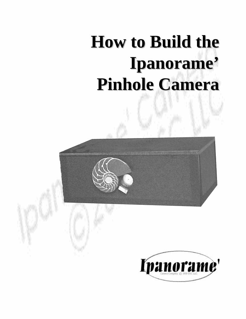
How to Build theHow to Build theIpanorame’Ipanorame’
Pinhole CameraPinhole Camera
How to Build the Ipanorama’ Pinhole Camera, First EditionHow to Build the Ipanorama’ Pinhole Camera, First EditionDSC LLC All Rights ReservedCopyright ©2003 DSC LLC
Notice of Rights
All rights reserved, no part of this book may be reproduced or transmitted in any form or by any means,electronic, mechanical, photocopying, recording, or otherwise, without prior written permission of thepublisher. For more information contact DSC LLC at [email protected].
Notice of Liability
The information in this book is distributed as-is without warranty. While every effort has been made to assurethe accuracy of the information contained within this book, neither the author or DSC LLC shall have anyliability to any person or or entity with respect to any loss, injury or damage either direct or indirect as asubsequence of following the instruction and producing the product(s) described herein.
Trademarks
Ipanorama’ and DSC LLC are trademarks of DSC LLC. Wherein many designations made by manufacturers ,service organizations and publishers are claimed as trademarks, when DSC LLC is aware of these trademarks,they are represented in this book as they appear as requested by the manufacturer. All product names,trademarks and services indentified throughout this book are used in editorial fashion only and for the benefitof such companies. No use, or the use of any trade name is intended to convey endorsement or other affiliationwith this book.
Printed and Bound in the United States of America
2
BeginningsBeginnings
Most people are quite amazed by the idea that apicture can be taken by a camera that has nolens. It’s the unique qualities light that allowspinhole cameras to capture photographs in theirmost basic form. You’re about to build awonderful camera that takes advantage of thesesimple qualities and produce beautiful, creativeimages.
The Nature of the The Nature of the CameraCamera
Since light travels in a straight line, lightreflecting off of a surface will converge into apinhole camera’s aperture and emerge within thecamera as a cone of light onto the film’s surface.
Pinhole size determines the clarity of the image.Too small a pinhole and diffraction effectsoccur. Too large and the light fails to convergein an organized manner - either way blurring theresultant image
The proper size pinhole is one that allows thebest image to form on the film and is determinedby the focal length - the distance from thepinhole aperture to the film’s surface.
The ImageThe Image
A pinhole camera’s image will be slightly fuzzy,inverted and horizontally reversed. Also, sincethe aperture is so small, depth of field will beinfinite and the image will be in focus across thewhole surface of the film.
People often feel that the images produced bypinhole cameras are somewhat ghostly anddelicate. This is a desirable characteristic ofpinhole photography and is part of the fun ofbuilding and using your own pinhole camera.
Construction PhilosophyConstruction Philosophy
Building a durable and useful pinhole camerashouldn’t be a difficult task. With the advent ofmaterials such as Foamboard™, it’s no longernecessary to have a collection of wood ormetalworking tools to create a high-qualitycamera - in fact, the only tools you’ll need are agood quality metal straightedge, a hobby knife,some ‘T’-pins, clothespins and glue.
To further enhance the enjoyment of thebuilding experience, the printed plans sheetsthat accompany this book are used directly astemplates when cutting the Foamboard™ . Theneed to perform tedious measurements is keptto an absolute minimum.
As for the building materials, simplicity is thekeyword. 3/16” Foamboard™ is the mainingredients with a couple of brass or nylonhardware items thrown in. Total cost should beunder $10 depending on where you purchaseyour materials.
Patience is a good quality for a photographer tohave, but theres nothing wrong with instantgratification. Building a camera need not be along-term project. During the development ofthe Ipanorama’™ Pinhole Camera, manyprototype, experimental and productioncameras were built. In most cases the totalbuilding time was between three and five hours.Depending on the glue type, you can build acamera in the morning and be out takingpictures after lunch!
Getting UnderwayGetting Underway
The first thing to do is acquire the buildingmaterials and tools you’ll need to construct thecamera.
This book was written to describe theconstruction of a single camera. However bybuying the required amount of buildingmaterials and saving the template, severalcameras could be built.
3
Building MaterialsBuilding Materials
Here what you’ll need. All of it can be found in awell stocked hobby or crafts supply store.Qty Size Item1 Sheet 18” X 22” X 3/16” Black Foamboard1 Sheet Paper thin Brass Sheet1 6-32 X 1/2” Nylon* Round Bolt1 6-32 Nylon* Nut2 6-32 Nylon* Washers
* Brass could substituted
Small Nylon ™ bolts, nuts and washers can befound in any of the larger hardware stores. EitherNylon™ or brass is suitable.
Construction SuppliesConstruction Supplies
Qty Item1 Tube Contact Adhesive6 Small Spring-type clothespins1 Box #11 X-Acto™ type blades25 1” long T-Pins1 Can Stencil Spray Adhesive1 roll Masking Tape (Black preferred)1 Sht Light sandpaper
The best contact adhesive for Foamboard™
construction is Bond 527 ™ or similar. T-Pins areavailable in craft stores or hobby shops.
ToolsTools
Qty Item1 Aluminum straightedge or ruler1 Hobby knife for #11 blades1 pr Good scissors1 Small Blade Screwdriver1 Small Pliers1 #10 or #12 Sewing Needle
Your WorkspaceYour Workspace
Find a well lit, flat workspace that is largeenough to roll out the template plans onto theFoamboard ™ and give you some working roomto hold your tools and materials.
You’ll need a cutting surface such as a section ofLinoleum tile or something similar to cut on soyou won’t damage your work surface.
Some Some Foamboard™ Construction Notes...Construction Notes...
GlueGlue -Choice of glue is critical in the successfulcontruction of your camera. Avoid white orwood glue. It simply doesn’t have the holdingpower of the newer contact adhesives.
Gap-filling Super Glue is well suited tobuilding Foamboard™ structures. It hardensalmost instantly but is is expensive and cangive off irritating fumes. However, you canbuild the camera very quickly using this type ofglue.
The best glue to use is the Bond 527 ™available in craft stores. It dries quickly and isvery strong. Although the camera could be usedwithin an hour of construction if handled verycarefully, it’s best to let it dry overnight.
With Bond 527 ™ , the most durable glue jointsare made by coating both pieces, pressing themtogether for a moment, pulling them apart andwaiting 30 seconds, then pressing them togetherand securing with clothespins and T-Pins untildry.
CuttingCuttingAlways use a cutting surface and a new, sharpblade in a proper handle. Keep the blade asstraight up as possible to maintain a goodperpendicular Foamboard™ edge.
Cut Foamboard™ in several passes. Don’t tryto cut through all at once. On the first pass, cutthrough the top paper. On the second pass, cutthrough the foam and on the final pass, cut thebottom paper. This will give you the bestcleanest edges and the best results.
Clamping and PinningClamping and PinningOnce the pieces are pressed together, push T-Pins into the mating edges to establishalignment and some clamping force. Useclothespins to clamp flat board section togetherwhile drying.
4
Start Building!Start Building!
* If you are going to make several cameras, savethe template page by having it copied at anycopy center or blueprinting service - or - tracethe template onto another sheet of paper firstand save the original.
Cutting Out the PartsCutting Out the Parts
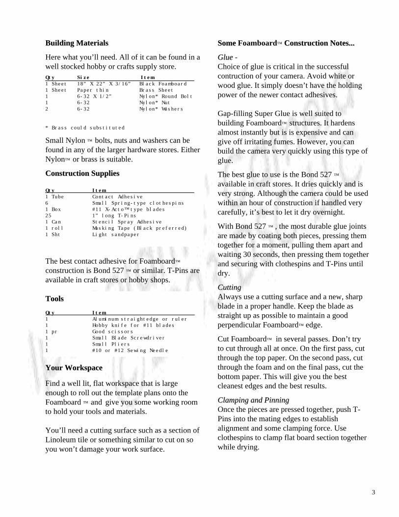
• Lay out the Foamboard™ on your worksurface.Prepare the template sheet by lightly spraying itwith the Stencil Adhesive Spray in a wellventilated area away from any open flame-preferably outside.
• Install a new, sharp blade into your hobbyknife. Using the straghtedge as a guide, cut outthe Foamboard parts. Read the instructions onthe template page about the blade thicknessallowance so the parts are cut to the proper size.Cut using the three-pass method describe on thepreceding page.
• Transfer the template to the Foamboard ™ andsmooth it onto the surface as straight as possible.Allow to dry about 5 minutes. Don’t allow anywrinkles to form. The Stencil Spray Glue isremovable, so adjust the template as needed tohave a smooth surface.
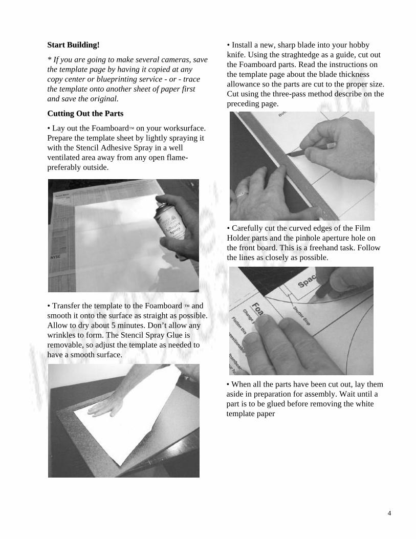
• Carefully cut the curved edges of the FilmHolder parts and the pinhole aperture hole onthe front board. This is a freehand task. Followthe lines as closely as possible.
• When all the parts have been cut out, lay themaside in preparation for assembly. Wait until apart is to be glued before removing the whitetemplate paper
5
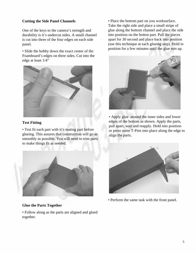
Cutting the Side Panel Channels
One of the keys to the camera’s strength anddurability is it’s undercut sides. A small channelis cut into three of the four edges on each sidepanel.
• Slide the hobby down the exact center of theFoamboard’s edges on three sides. Cut into theedge at least 1/4”
Test Fitting
• Test fit each part with it’s mating part beforeglueing. This assures that construction will go assmoothly as possible. You will need to trim partsto make things fit as needed.
Glue the Parts Together
• Follow along as the parts are aligned and gluedtogether.
• Place the bottom part on you worksurface.Take the right side and place a small stripe ofglue along the bottom channel and place the sideinto position on the botton part. Pull the piecesapart for 30 second and place back into position(use this technique at each glueing step). Hold inposition for a few minutes until the glue sets up.
• Perform the same task with the front panel.
• Apply glue around the inner sides and loweredges of the bottom as shown. Apply the parts,pull apart, wait and reapply. Hold into positionor press some T-Pins into place along the edge toalign the parts.
6
• Apply T-Pins where needed to keep the parts inplace and aligned. Allow this entire assembly setup for about an hour to be on the safe side beforeproceeding
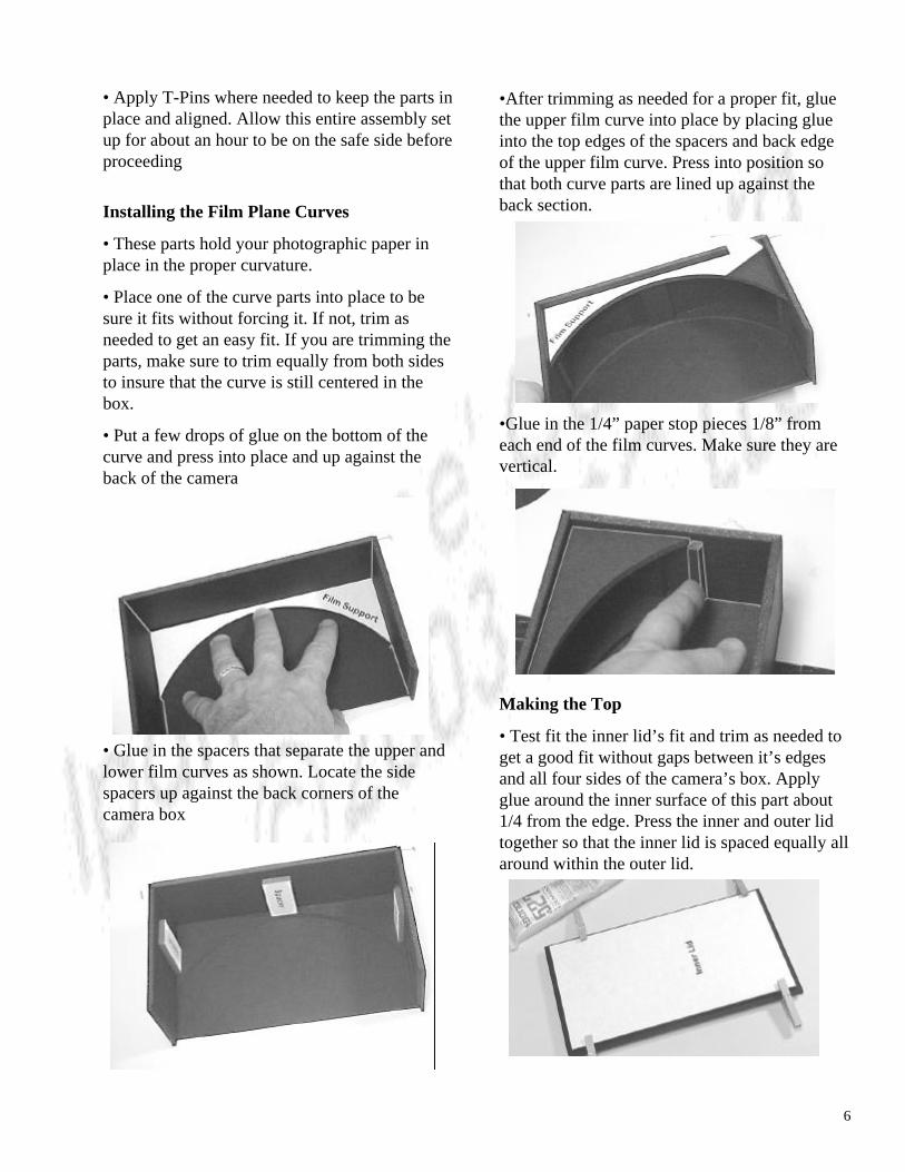
Installing the Film Plane Curves
• These parts hold your photographic paper inplace in the proper curvature.
• Place one of the curve parts into place to besure it fits without forcing it. If not, trim asneeded to get an easy fit. If you are trimming theparts, make sure to trim equally from both sidesto insure that the curve is still centered in thebox.
• Put a few drops of glue on the bottom of thecurve and press into place and up against theback of the camera
•After trimming as needed for a proper fit, gluethe upper film curve into place by placing glueinto the top edges of the spacers and back edgeof the upper film curve. Press into position sothat both curve parts are lined up against theback section.
Making the Top
• Test fit the inner lid’s fit and trim as needed toget a good fit without gaps between it’s edgesand all four sides of the camera’s box. Applyglue around the inner surface of this part about1/4 from the edge. Press the inner and outer lidtogether so that the inner lid is spaced equally allaround within the outer lid.
• Glue in the spacers that separate the upper andlower film curves as shown. Locate the sidespacers up against the back corners of thecamera box
•Glue in the 1/4” paper stop pieces 1/8” fromeach end of the film curves. Make sure they arevertical.
7
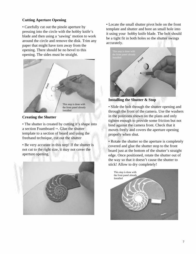
Cutting Aperture Opening
• Carefully cut out the pinole aperture bypressing into the circle with the hobby knife’sblade and then using a ‘sawing’ motion to workaround the circle and remove the disk. Trim anypaper that might have torn away from theopening. There should be no bevel to thisopening. The sides must be straight.
Creating the Shutter
• The shutter is created by cutting it’s shape intoa section Foamboard ™. Glue the shuttertemplate to a section of board and using thefreehand technique, cut out the shutter
• Be very accurate in this step! If the shutter isnot cut to the right size, it may not cover theaperture opening.
• Locate the small shutter pivot hole on the fronttemplate and shutter and bore an small hole intoit using your hobby knife blade. The bolt shouldbe a tight fit in both holes so the shutter swingsaccurately.
Installing the Shutter & Stop
• Slide the bolt through the shutter opening andthrough the front of the camera. Use the washersin the positions shown on the plans and onlytighten enough to provide some friction but notbind against the camera front. Check that itmoves freely and covers the aperture openingproperly when shut.
• Rotate the shutter so the aperture is completelycovered and glue the shutter stop to the frontboard just at the bottom of the shutter’s straightedge. Once positioned, rotate the shutter out ofthe way so that it doesn’t cause the shutter tostick! Allow to dry completely!
This step is done withthe front panel alreadyInstalled
This step is done withthe front panel alreadyInstalled
This step is done withthe front panel alreadyInstalled
9
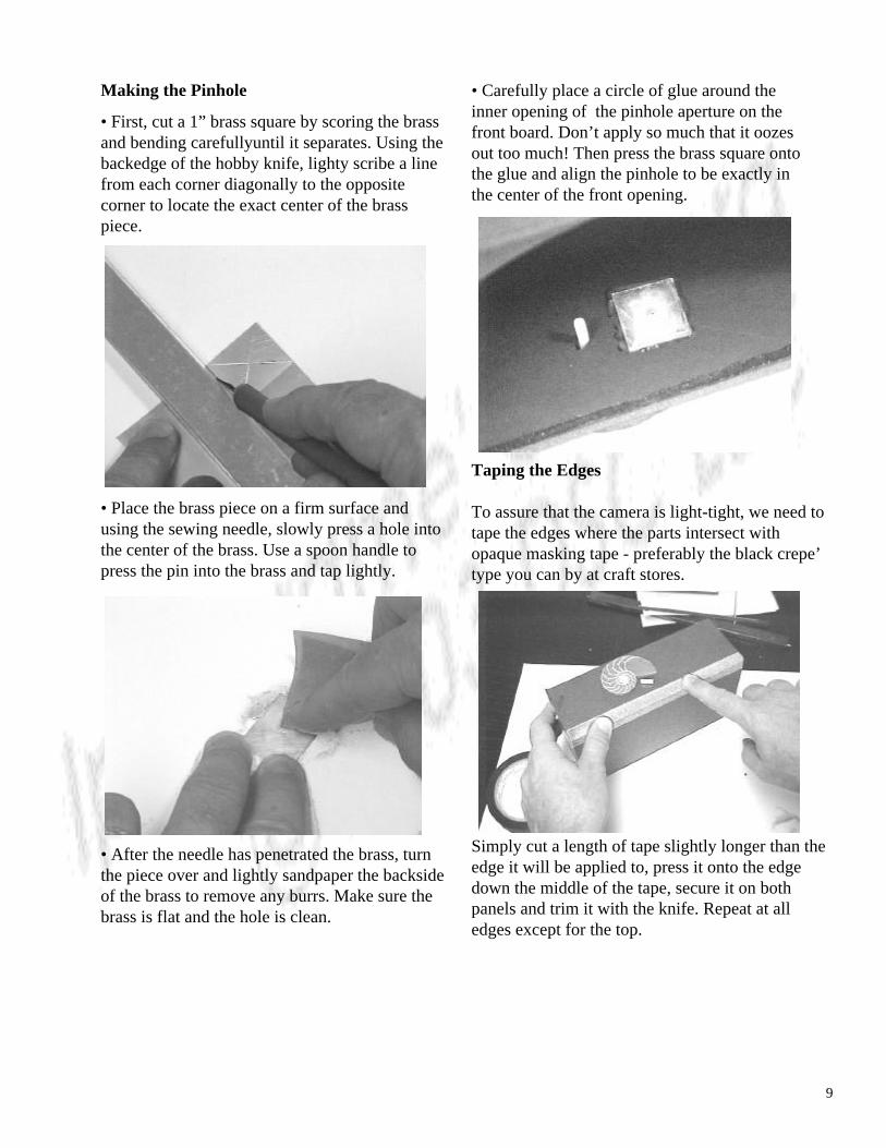
Making the Pinhole
• First, cut a 1” brass square by scoring the brassand bending carefullyuntil it separates. Using thebackedge of the hobby knife, lighty scribe a linefrom each corner diagonally to the oppositecorner to locate the exact center of the brasspiece.
• Place the brass piece on a firm surface andusing the sewing needle, slowly press a hole intothe center of the brass. Use a spoon handle topress the pin into the brass and tap lightly.
• After the needle has penetrated the brass, turnthe piece over and lightly sandpaper the backsideof the brass to remove any burrs. Make sure thebrass is flat and the hole is clean.
• Carefully place a circle of glue around theinner opening of the pinhole aperture on thefront board. Don’t apply so much that it oozesout too much! Then press the brass square ontothe glue and align the pinhole to be exactly inthe center of the front opening.
Taping the Edges
To assure that the camera is light-tight, we need totape the edges where the parts intersect withopaque masking tape - preferably the black crepe’type you can by at craft stores.
Simply cut a length of tape slightly longer than theedge it will be applied to, press it onto the edgedown the middle of the tape, secure it on bothpanels and trim it with the knife. Repeat at alledges except for the top.
10
Using Your Camera
A camera is really a projector. A pinhole cameradirects light into an image just as a lens would,except it uses a small opening in a metal sheetinstead of a glass or plastic lens to organize thelight’s rays.
Unlike a pinhole, a typical camera lens gainsthickness when measured from it’s edge to it’scenter. Light passing through the lens will focusat different points depending on where it camethrough the lens. That’s why a large aperture hasa shallow depth of field and a small aperture hasa deep one. Lens thickness with a small apertureis almost constant, since the opening only allowslight to pass through the center of the glass. Alarge opening allows light to pass throughvarying thickness of glass and focus at differentpoints.
A pinhole on the other hand has no thicknessvariations. Except for the brass it’s drilled into, ithas no thickness at all. The pinhole’s sizedetermines the sharpness of your image. If thepinhole is too large, too much light enters,blurring the image. Too small and the edges ofthe brass hole interfere with the light and theimage loses form.
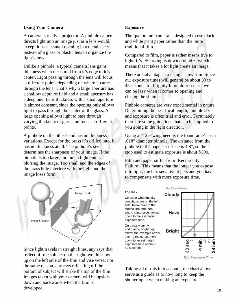
Since light travels in straight lines, any rays thatreflect off the subject on the right, would showup on the left side of the film and vise versa. Forthe same reason, any rays reflecting off thebottom of subject will strike the top of the film.Images taken with your camera will be upside-down and backwards when the film isdeveloped.
Image Outside
Image Inside
Exposure
The Ipanorame’ camera is designed to use blackand white print paper rather than the moretraditional film.
Compared to film, paper is rather insensitive tolight. It’s ISO rating is down around 6, whichmeans that it takes a lot light create an image.
There are advantages to using a slow film. Sinceour exposure times will general be about 30 to45 seconds for brightly lit outdoor scenes, wecan be lazy when it comes to opening andclosing the shutter.
Pinhole cameras are very experimental in nature.Determining the best focal length, pinhole sizeand exposure is often trial and error. Fortunatelythere are some guidelines that can be applied toyou going in the right direction.
Using a #12 sewing needle, the Ipanorame’ has a.018” diameter pinhole. The distance from thepinhole to the paper’s surface is 4.8”, so the f-stop used to estimate exposure is about f/300.
Film and paper suffer from ‘ReciprocityFailure’. This means that the longer you exposeit to light, the less sensitive it gets and you haveto compensate with more exposure time.
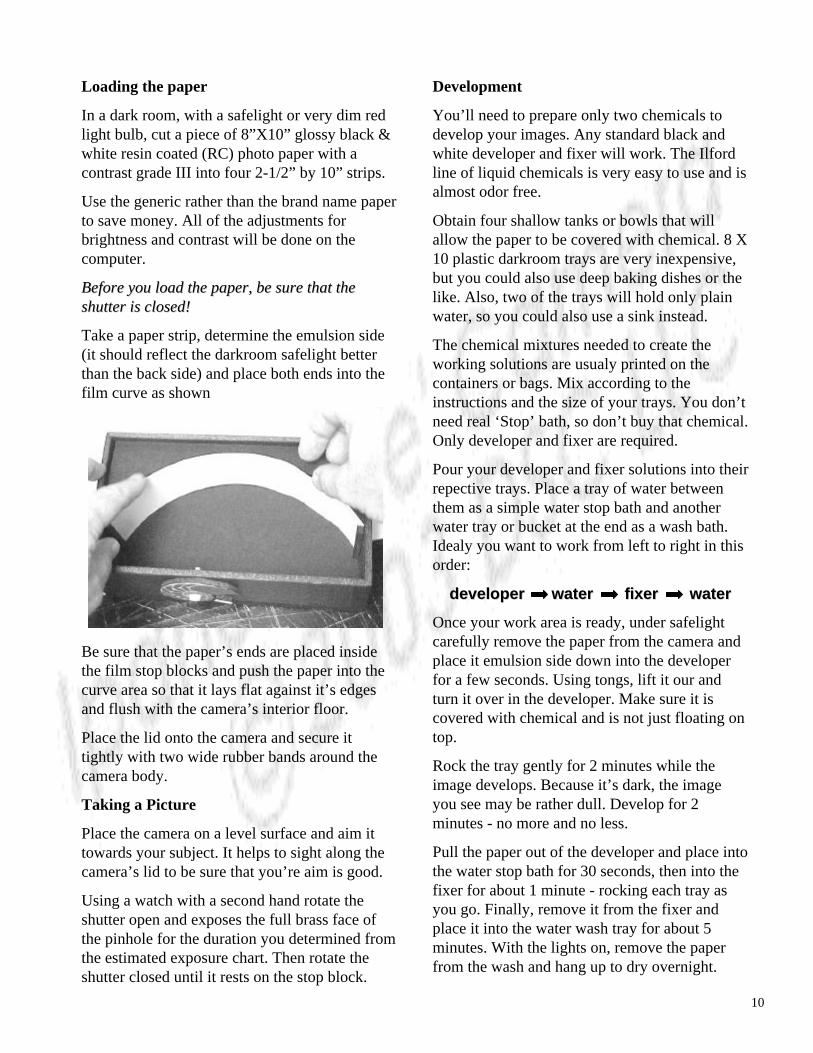
Taking all of this into account, the chart aboveserve as a guide as to how long to keep theshutter open when making an exposure.
To Use -
Consider what the skyconditions are on the left side, follow over to thecurved line and then,where it intersects, followdown to the estimatedexposure time.
On a really sunnyand glaring bright day, follow the example arrow over to the curve, then down to an estimatedexposure time of about40 seconds.
2 3 10
20
10
Loading the paper
In a dark room, with a safelight or very dim redlight bulb, cut a piece of 8”X10” glossy black &white resin coated (RC) photo paper with acontrast grade III into four 2-1/2” by 10” strips.
Use the generic rather than the brand name paperto save money. All of the adjustments forbrightness and contrast will be done on thecomputer.
Before you load the paper, be sure that theBefore you load the paper, be sure that theshutter is closed!shutter is closed!
Take a paper strip, determine the emulsion side(it should reflect the darkroom safelight betterthan the back side) and place both ends into thefilm curve as shown
Be sure that the paper’s ends are placed insidethe film stop blocks and push the paper into thecurve area so that it lays flat against it’s edgesand flush with the camera’s interior floor.
Place the lid onto the camera and secure ittightly with two wide rubber bands around thecamera body.
Taking a Picture
Place the camera on a level surface and aim ittowards your subject. It helps to sight along thecamera’s lid to be sure that you’re aim is good.
Using a watch with a second hand rotate theshutter open and exposes the full brass face ofthe pinhole for the duration you determined fromthe estimated exposure chart. Then rotate theshutter closed until it rests on the stop block.
Development
You’ll need to prepare only two chemicals todevelop your images. Any standard black andwhite developer and fixer will work. The Ilfordline of liquid chemicals is very easy to use and isalmost odor free.
Obtain four shallow tanks or bowls that willallow the paper to be covered with chemical. 8 X10 plastic darkroom trays are very inexpensive,but you could also use deep baking dishes or thelike. Also, two of the trays will hold only plainwater, so you could also use a sink instead.
The chemical mixtures needed to create theworking solutions are usualy printed on thecontainers or bags. Mix according to theinstructions and the size of your trays. You don’tneed real ‘Stop’ bath, so don’t buy that chemical.Only developer and fixer are required.
Pour your developer and fixer solutions into theirrepective trays. Place a tray of water betweenthem as a simple water stop bath and anotherwater tray or bucket at the end as a wash bath.Idealy you want to work from left to right in thisorder:
developer water fixer waterdeveloper water fixer water
Once your work area is ready, under safelightcarefully remove the paper from the camera andplace it emulsion side down into the developerfor a few seconds. Using tongs, lift it our andturn it over in the developer. Make sure it iscovered with chemical and is not just floating ontop.
Rock the tray gently for 2 minutes while theimage develops. Because it’s dark, the imageyou see may be rather dull. Develop for 2minutes - no more and no less.
Pull the paper out of the developer and place intothe water stop bath for 30 seconds, then into thefixer for about 1 minute - rocking each tray asyou go. Finally, remove it from the fixer andplace it into the water wash tray for about 5minutes. With the lights on, remove the paperfrom the wash and hang up to dry overnight.

10
Scanning the Image
If all went as expected, you’ll notice that theimage on the developed paper is a negative,mirrored image of your subject. You’ll need toscan it into an image editing computer programto invert and remirror it to the proper orientation.
While there are too many computer programsavailable to discuss each one, there are someguidelines for scanning, manipulating andprinting your picture
First, remember that the greater the DPI - DotsPer Inch of the scan, the bigger the file size. Agood compromise would be 150 DPI forscanning - or try 300 DPI if you don’t like thepicture quality.
Place your picture face down on your scannerand using whatever software application you’rechosen, scan the image. Most likely you can tellyour scanning program that the picture is only 21/2” X 10 so you don’t have to crop it later.
Invert and Mirror
Once the picture has been scanned and is on-screen to be edited, you’ll need to invert theimage then mirror it horizontally. After it looksthe way your subject did, you can adjust it’sbrightness and contrast to suite yourexpectations.
If you feel that the image is a bit fuzzy and coulduse some sharpening, the best way to do this iswith the “Unsharp Mask” filter available onsome of the higher-end image editing software.
This is a good time to name and save yourimage. A common image file format is the .JPG.While this is a good choice, it can degrade thequality of your picture through it’s ability tocompress the file to make it smaller. If youchoose a .JPG format, select a compressionquantity of 25% or less to keep your picturelooking good.
Printing
Modern inkjet printers have the ability toproduce pictures that rival and sometime exceedthe quality of those generated by traditionalphotographic printers. While the quality of theprinted picture is dependent on a number offactors - the scanned image, the paper, ink anddelivery method, the overall results are usuallyquite good.
One drawback of the average inkjet printer is it’suse of color mixing to produce black or grey. Ifyours does this, and most do, you may see someslight color cast to your black and white printedpicture. The printer used to develop and test theIpanorame’ is the Canon i470 Photo Printer.
Nevertheless, if your printer requires it, choosethe ‘photo’ cartridge option and the highestprinting resolution for your output and alwaysprint on photo quality inkjet paper, not the plainletter type. Don’t be tempted to scale yourpicture larger or smaller either, it will degradethe quality and you won’t get the best results.
That’s about it!
Pinhole cameras are supposed to be fun to buildand use. If they are too much work, neither goalwill be fulfilled. Hopefully you’ll enjoy yourIpanorame’ camera and will be inspired to comeup with new ideas for your own pinhole cameras.