
The Ion Propulsion System for the Solar Electric...
13
Joint Conference of 30th ISTS, 34th IEPC and 6th NSAT, Kobe-Hyogo, Japan July 4 – 10, 2015 1 The Ion Propulsion System for the Solar Electric Propulsion Technology Demonstration Mission IEPC-2015-008 /ISTS-2015-b-008 Presented at Joint Conference of 30th International Symposium on Space Technology and Science 34th International Electric Propulsion Conference and 6th Nano-satellite Symposium, Hyogo-Kobe, Japan July 4 – 10, 2015 Daniel A. Herman, 1 Walter Santiago, 2 and Hani Kamhawi 3 NASA Glenn Research Center, Cleveland, Ohio, 44135, United States and James E. Polk, 4 John Steven Snyder, 5 Richard R. Hofer, 6 and J. Morgan Parker 7 Jet Propulsion Laboratory, Pasadena, CA, 91109 Abstract: The Asteroid Redirect Robotic Mission is a candidate Solar Electric Propulsion Technology Demonstration Mission whose main objectives are to develop and demonstrate a high-power solar electric propulsion capability for the Agency and return an asteroidal mass for rendezvous and characterization in a companion human-crewed mission. The ion propulsion system must be capable of operating over an 8-year time period and processing up to 10,000 kg of xenon propellant. This high-power solar electric propulsion capability, or an extensible derivative of it, has been identified as a critical part of an affordable, beyond-low-Earth-orbit, manned-exploration architecture. Under the NASA Space Technology Mission Directorate the critical electric propulsion and solar array technologies are being developed. The ion propulsion system being co-developed by the NASA Glenn Research Center and the Jet Propulsion Laboratory for the Asteroid Redirect Vehicle is based on the NASA-developed 12.5 kW Hall Effect Rocket with Magnetic Shielding (HERMeS0 thruster and power processing technologies. This paper presents the conceptual design for the ion propulsion system, the status of the NASA in-house thruster and power processing activity, and an update on flight hardware. 1 Ion Propulsion System (IPS) Lead, Electric Propulsion Systems Branch, [email protected]. 2 IPS Power Processing Lead, Power Management and Distribution Branch, [email protected]. 3 IPS Deputy Thruster Lead, Electric Propulsion Systems Branch, [email protected]. 4 IPS Deputy Lead, Propulsion, Thermal, and Materials Engineering Section, [email protected]. 5 IPS System Engineering Lead, Electric Propulsion Group, [email protected]. 6 IPS Thruster Lead, Electric Propulsion Group, [email protected]. 7 IPS Tank and Xenon Feed System Lead, Propulsion and Fluid Flight Systems Group, [email protected].
Transcript of The Ion Propulsion System for the Solar Electric...

Joint Conference of 30th ISTS, 34th IEPC and 6th NSAT, Kobe-Hyogo, JapanJuly 4 – 10, 2015
1
The Ion Propulsion System for the Solar Electric Propulsion Technology Demonstration Mission
IEPC-2015-008 /ISTS-2015-b-008
Presented at Joint Conference of 30th International Symposium on Space Technology and Science34th International Electric Propulsion Conference and 6th Nano-satellite Symposium,
Hyogo-Kobe, JapanJuly 4 – 10, 2015
Daniel A. Herman,1 Walter Santiago,2 and Hani Kamhawi3
NASA Glenn Research Center, Cleveland, Ohio, 44135, United States
and
James E. Polk,4 John Steven Snyder,5 Richard R. Hofer,6 and J. Morgan Parker7
Jet Propulsion Laboratory, Pasadena, CA, 91109
Abstract: The Asteroid Redirect Robotic Mission is a candidate Solar Electric Propulsion Technology Demonstration Mission whose main objectives are to develop and demonstrate a high-power solar electric propulsion capability for the Agency and return an asteroidal mass for rendezvous and characterization in a companion human-crewed mission.The ion propulsion system must be capable of operating over an 8-year time period and processing up to 10,000 kg of xenon propellant. This high-power solar electric propulsion capability, or an extensible derivative of it, has been identified as a critical part of an affordable, beyond-low-Earth-orbit, manned-exploration architecture. Under the NASA Space Technology Mission Directorate the critical electric propulsion and solar array technologies are being developed. The ion propulsion system being co-developed by the NASA Glenn Research Center and the Jet Propulsion Laboratory for the Asteroid Redirect Vehicle is based on the NASA-developed 12.5 kW Hall Effect Rocket with Magnetic Shielding (HERMeS0 thruster and power processing technologies. This paper presents theconceptual design for the ion propulsion system, the status of the NASA in-house thruster and power processing activity, and an update on flight hardware.
1 Ion Propulsion System (IPS) Lead, Electric Propulsion Systems Branch, [email protected] IPS Power Processing Lead, Power Management and Distribution Branch, [email protected] IPS Deputy Thruster Lead, Electric Propulsion Systems Branch, [email protected] IPS Deputy Lead, Propulsion, Thermal, and Materials Engineering Section, [email protected] IPS System Engineering Lead, Electric Propulsion Group, [email protected] IPS Thruster Lead, Electric Propulsion Group, [email protected] IPS Tank and Xenon Feed System Lead, Propulsion and Fluid Flight Systems Group, [email protected].

Joint Conference of 30th ISTS, 34th IEPC and 6th NSAT, Kobe-Hyogo, JapanJuly 4 – 10, 2015
2
I. IntroductionOR missions beyond low Earth orbit, spacecraft size and mass can be dominated by onboard chemical propulsion systems and propellants that may constitute more than 50 percent of the spacecraft mass. This impact
can be substantially reduced through the utilization of Solar Electric Propulsion (SEP) due to its substantially higher specific impulse. Studies performed for NASA’s Human Exploration and Operations Mission Directorate and Science Mission Directorate have demonstrated that a 50kW-class SEP capability can be enabling for both near term and future architectures and science missions.1 A high-power SEP element is integral to the Evolvable Mars Campaign, illustrated in Fig. 1, which presents an approach to establish an affordable evolutionary human exploration architecture. To enable SEP missions at the power levels required for these applications, an in-space demonstration of an operational 50kW-class SEP spacecraft has been proposed as a SEP Technology Demonstration Mission (TDM). In 2010 NASA’s Space Technology Mission Directorate (STMD) began developing large, deployablephotovoltaic solar array structures for high-power electrical power production and high-power electric propulsion technologies.2-7 The maturation of thesecritical technologies has made mission concepts utilizing high-power SEP viable.
The Asteroid Redirect Robotic Mission (ARRM) is an SEP TDM concept that utilizes an SEP spacecraft to return up to 20 metric tons (with a largest dimension of up to 6 m diameter) of asteroidal mass from the surface of a larger asteroid, to a stable orbit around the Moon for subsequent access by a human crewed mission.8-12 The Asteroid Redirect Vehicle (ARV) concept, shown in Fig. 2, is a 50kW-class spacecraft having a total mass of 15 metric tons including up to 10,000 kilograms of xenon propellant. ARRM would satisfy the SEP TDM objectives while simultaneously providing a transportation capability with the potential for follow-on NASA applications either as is or with further modifications referred to as block upgrades.2
The Ion Propulsion System (IPS) being co-developed by the NASA Glenn Research Center and the Jet Propulsion Laboratory for ARRM will be used for heliocentric transfer from Earth to the target asteroid, orbit capture at the asteroid, transfer to a low orbit about the asteroid, a planetary defense demonstration after retrieval of the asteroidal mass from the larger asteroid, departure and escape from the asteroid, the heliocentric transfer from the asteroid to lunar orbit, and insertion into a lunar distant retrograde orbit. In addition, the IPS will provide pitch and yaw control of the spacecraft during IPS thrusting. The required total impulse provided by the IPS is 3x10⁸ N-s, by far the largest total impulse ever provided by an on-board propulsion system for a planetary spacecraft.
F
Figure 1. Evolvable Mars Campaign (EMC) graphical depiction.
Figure 2. Asteroid Redirect Vehicle (ARV) Conceptual Design(arrays not shown).
12.5kW Hall Thrusters [Quantity 4]
Xenon Tanks[Quantity 8]
Radiators (4 PPU’s mounted on inside)
[Quantity 2]

Joint Conference of 30th ISTS, 34th IEPC and 6th NSAT, Kobe-Hyogo, JapanJuly 4 – 10, 2015
3
II. Ion Propulsion System DescriptionThe key driving requirements for the ARRM IPS, shown in Table 1, are that it must be single fault tolerant while
processing up to 10,000 kg of xenon, providing a total impulse of 3x10⁸ N-s over an input power range of 6.67 to 40 kW with input voltages ranging from 95 to 140 V and a mission duration of eight years.
Table 1. Key ARRM Requirements for the Ion Propulsion System.Capability ValueTotal system power 40 kWMaximum specific impulse 3000 sXenon throughput 10,000 kgString fault tolerance SingleSolar range 0.8 – 1.9 AUInput voltage range 95 – 140 V
A. IPS Functional DescriptionThe ARRM IPS is comprised of the following four elements:
1. Flight Thruster (FT).2. Power Processor Unity (PPU).3. Xenon Feed System (XFS).4. Mechanical Integration Hardware (MIH) including cabling.
The technology investments by the Space Technology Mission Directorate has been critical in establishing the viability of the IPS for ARRM. A risk assessment of the ARV spacecraft bus revealed that four of the top six technical risks reside within the IPS. The electric propulsion investment and component development plans were formulated to address these technical risks to assure mission success. These technical risks are:
Hall Thruster Lifetime Qualification: The mission development schedule for ARRM precludes wear testing on the ground for the durations conventionally required. This necessarily means exceptions to the standard electric propulsion life qualification approach.13 An approach to certifying the life of the thruster is being developed that relies on physics-based modeling and limited testing of the primary wear-out failure modes. This approach is designed to mitigate the risk that non-traditional life qualification required by mission schedule will result in reduced mission capability.
Hall Thruster Ground Test Facility Effects: The performance, stability, thermal, and wear characteristics of electric thrusters measured during ground-based tests are influenced to some degree by the limitations of ground test facilities. Some of these limitations include finite operating pressures, volume constraints, the influence of grounded vacuum chamber walls, thermal environments that are non-representative of space, and backsputter from facility equipment and chamber walls. The development plan for the Hall Effect Rocket with Magnetic Shielding (HERMeS) thruster includes efforts to quantify facility effects and to develop designs or methodologies to mitigate them such that the performance and life of HERMeS may be reliably predicted during in-space operation. This approach is designed to mitigate the risk that performance or wear characteristics could significantly differ between the qualification in ground-based facilities and in-flight.
PPU Development Schedule: Electric thruster PPU development is typically the pacing activity for an EP system development and testing has, in some instances, encountered issues that required significant additional resource to address (e.g. Dawn14). This risk is exacerbated by the brevity of the duration for qualification and flight unit fabrication required to meet the target launch date for ARRM. There is a risk that the PPU development will encounter similar problems that will have cost and schedule impacts.This risk is being mitigated by performing the in-house NASA PPU development, reducing the complexity of the PPU, simplifying requirements where possible, and contracting for engineering model hardware development and flight units early in the mission design cycle.
New Xenon Tank Development: New tank development and testing issues can also require significant additional resources and/or result in reduced mission capability if problems are encountered. To mitigate this risk, a seamless, aluminum-lined tank is being developed that utilizes existing manufacturing tooling for the conceptual ARV. Recent efforts have also been focused on development of a pathfinder xenon tank to address the new xenon tank development risks.

Joint Conference of 30th ISTS, 34th IEPC and 6th NSAT, Kobe-Hyogo, JapanJuly 4 – 10, 2015
4
The 2-axis thruster gimbal assembly work breakdown is included in the Structures and Mechanisms System for the conceptual ARV. A high-level block diagram, shown in Fig. 3, indicates that the conceptual ARV IPS includes four flight electric propulsion (EP) strings, a xenon feed system, and the interconnecting cabling and tubing. Each EP string consists of a Hall thruster, a PPU, a xenon flow controller, and the interconnecting cable harnesses. The xenon feed system consists of eight xenon tanks, a propellant management assembly, and the xenon flow controllers.Each EP string is operated independently of the others by the spacecraft. Single fault tolerance is maintained by block-redundancy at the EP string level with internal redundancy for the xenon feed system components outside of the EP strings.
III. Subsystem DescriptionsIn 2010 NASA’s Space Technology Mission Directorate (STMD) began developing large, deployable
photovoltaic solar array structures for high-power electrical power generation and high-power electric propulsion technologies.2-7 The maturation of the critical technologies required for the high-power SEP vehicle has made mission concepts utilizing high-power SEP viable.15 The high-power electric propulsion investments were in areas assessed as having high technical risks and/or long-lead times for the IPS. NASA in-house development of the 12.5 kW Hall thruster and power processing unit have resulted in two high-fidelity development model thrusters and a brassboard power processing unit that have been extensively tested and characterized separately as well asdemonstrated as an integrated system. The NASA work validated subsystem design methodologies, developed critical diagnostics, demonstrated performance that meets current mission requirements, made significant strides in life qualification, developed and validated an array of models, and potentially provided a departure point for the technology maturation and flight system development within industry for the mission. The conceptual design of the IPS components for the current ARV concept is described below.
PPU 1
PPU 2
PPU 3
PPU 4
XFC1
XFC2
XFC3
XFC4
FT1
FT2
FT3
FT4
28 V Power
High-Voltage Power
Propellant Line
Analog Telemetry
New Design
Other Mission Heritage
FT Flight Thruster
HPDU High Power Distribution Unit
PMA Propellant Management Assembly
PPU Power Processing Unit
XFC Xenon Flow Controller
Xenon Tank
Xenon Tank
Xenon Tank
Xenon Tank L Latch Valve
P Pressure Transducer
T Temperature Sensor
Manual Valve
Filter
LL
P T
P TP T
PMA
Digital I/O
P T
Xenon Tank
Xenon Tank
Xenon Tank
Xenon Tank
28 V PowerInput
Digital I/O(Avionics)
Analog Telemetry(Avionics)
Pressure Regulator
28 V Pulses
28 V PowerPulses (Avionics)
Figure 3. Top-Level ARRM Conceptual Ion Propulsion System (IPS) Block Diagram.

Joint Conference of 30th ISTS, 34th IEPC and 6th NSAT, Kobe-Hyogo, JapanJuly 4 – 10, 2015
5
Desired EP string performance for ARRM at beginning-of-life is shown in Table 2. The table utilizes the current best estimates from the in-house 12.5 kW thruster and PPU based on demonstrated performance includingexperimental uncertainty. The desired flight electric propulsion string should meet or exceed the performance in Table 2 while simultaneously meeting the ARRM lifetime requirement over all environmental conditions and input voltages.
Table 2. Electric propulsion string performance including experimental uncertainty.
EP String Total Input Power (kW)
Discharge Voltage (V) Thrust (mN)1
Mass Flow Rate (mg/s)2
System Efficiency3
13.33 400 686 30.66 0.5813.33 500 633 25.97 0.5813.33 600 589 22.91 0.5713.33 700 553 20.36 0.5613.33 800 526 18.52 0.5610.00 300 562 29.69 0.5310.00 400 521 24.30 0.5610.00 500 482 20.89 0.5610.00 600 446 18.31 0.5410.00 700 413 16.17 0.5310.00 800 342 12.88 0.456.67 300 386 21.65 0.526.67 400 342 17.55 0.506.67 500 311 14.83 0.496.67 600 267 11.43 0.476.67 700 242 9.99 0.44
1 Thrust shown here is Current Best Estimate minus experimental uncertainty.2 Mass flow rate shown here is Current Best Estimate plus experimental uncertainty.3 System Efficiency is shown here for information only (it is calculated directly from the other parameters).
B. Flight Thruster (FT)The conceptual ARV IPS design
utilizes the 12.5 kW Hall Effect Rocket with Magnetic Shielding (HERMeS). The HERMeS thruster design attributes from the ARRM mission requirements are shown in Table 3. HERMeS is unique because it is the first Hall thruster designed for magnetic shielding over its entire service life. The design of HERMeS incorporates technologies developed by NASA over nearly two decades, and is enabled through the use of magnetic shielding to effectively eliminate discharge chamber erosion.3,16-18 The result is a significant increase in the operational lifetime of state-of-the-art for Hall thrusters, with HERMeS being designed to operate at 3000 s specific impulse with a lifetime exceeding 50 kh. These capabilities are expected to meet or exceed the requirements for ARRM. The methodology used to design HERMeS emphasized the use of thermal, structural, and physics-based plasma modeling that were used in nearly every aspect of the thruster design to achieve its design goals.17,19,20 The design of HERMeS resulting from this approach uses an integrated magnetic and thermal design, pole piece covers, a graphite cathode keeper, an internally mounted cathode, and a downstream-plenum gas distributor.
Table 3. 12.5kW Hall-Effect Rocket with Magnetic Shielding (HERMeS) attributes (assuming 94% PPU efficiency).

Joint Conference of 30th ISTS, 34th IEPC and 6th NSAT, Kobe-Hyogo, JapanJuly 4 – 10, 2015
6
The HERMeS development plan was formulated from a set of technical risks that could impact mission success. Each element of the development plan is traceable to these risks. The development consists of three major hardware build phases: the Technology Development Unit (TDU), Engineering Development Unit (EDU), and the combined Qualification Model (QM) and Flight Model (FM) phases. HERMeS is now in the TDU phase, which is scheduled to complete by mid-2016, and the project is on track to complete all of its planned tasks prior to the EDU phase starting.
HERMeS Technology Demonstration Unit 1 (TDU-1) has been fabricated and has recently completed the first test campaign of its performance, stability, thermal, and wearcharacteristics. TDU-1 thruster is shown operating in VF5 at NASA GRC in Fig. 4. Figure 5 shows the operating conditions that have been investigated to date in the laboratory as discrete points overlaid on the operating envelope developed for ARRM. The completion of the first HERMeS test campaign has demonstrated thruster performance, verified magnetically shielded operation at high specific impulse, and affirmsthat the internally mounted cathode minimizes the effects of facility pressure on performance. Details regarding TDU thruster design, mission-required operating envelope, and test results that are being presented this summer at various conferences and in future publications are detailed in Refs. 3, 16, 17, and 19-35. A second thruster, TDU-2, is currently being fabricated and will undergo environmental testing by the end of 2015.
Figure 5. HERMeS operating envelope for the ARV IPS (shaded region) and the discrete operating conditions demonstrated to date in the laboratory (red markers).
Figure 4. 12.5kW Hall-Effect Rocket with Magnetic Shielding (HERMeS) operating in VF5 at NASA GRC.

Joint Conference of 30th ISTS, 34th IEPC and 6th NSAT, Kobe-Hyogo, JapanJuly 4 – 10, 2015
7
C. Power Processor Unit (PPU)The HP-120V PPU converts power from the 95 – 140 V spacecraft
solar arrays into the currents and voltages needed to start and operate the thruster. The PPU also communicates with the spacecraft and controls the xenon flow controller. The overall strategy for the NASA in-house power converter electronic design utilizes a full-bridge topology. This topology is good for high power applications because it has low electrical stress on the power transistors with efficienttransformer utilization. Metal-oxide-semiconductor field-effect transistors (MOSFETs) are paralleled as needed on each leg of the bridge to reduce conduction losses on the transistors. A full bridge topology is also used for the auxiliary supplies to allow for ample room for growth and to be able to reuse control and gate drive printed wiring boards.
For the NASA-developed HP-120V PPU, breadboard circuits of the power converter for the discharge and auxiliary supplies were built and tested. These were used to evaluate the main power transformer, output inductor, and gate drive circuit design. The design was then used to develop a brassboard PPU capable of operating in vacuum, but without the final form and fit of a flight PPU. The PPU brassboard unit was designed to operate in simulated operational environments in order to assess critical performance functions. The overall strategy for thermal design was to locate components with high dissipation like transformers, inductors, MOSFETs and diodes with a direct thermal path to the baseplate. Printed circuit boards have thermal planes and are mounted vertically to aluminum brackets that removed heat from the perimeter of the PCB into the baseplate.
The ARV performance estimates for the PPU are based upon measured values in the NASA-developed HP-120V PPU. The PPU processes electrical power from high voltage solar arrays and a 28 V unregulated, battery-backed bus. The brassboard unit powers a high power Hall thruster from 2 to 14 kW of discharge power and provides auxiliary outputs for inner and outer magnets, cathode keeper and heater. The discharge supply in this PPU is capable of supplying up to 800 V for specific impulse of 3,000 s and up to 14 kW of discharge power. The discharge supply consists of four discharge modules that may operate at a maximum of 3.5 kW each. The output current of each discharge module is limited to 20 A. Each discharge module can provide an output voltage of up to 200 V and the outputs are stacked in series to generate the required 800V output as shown in Fig. 6. When the required output voltage is lower than 400 V, two of the four discharge modules can be disabled by command to increase loading and improve performance. Bypass diodes were included to further improve performance when operating in this mode.
The desired PPU specifications changed after the HP-120V PPU, shown in Fig. 7, was already being fabricated.It was desired to increase the maximum PPU output current from 20 A up to 33 A to match the HERMeS thrustercapability. While this capability does not currently exist within the HP-120V PPU, with the addition of switches the four discharge modules could be reconfigured to provide 400V and 40A discharge output maximums. For the conceptual ARV design, this switching capability was assumed in order to estimate the system performance curves during the maturation of the ARRM mission concept.
Also in this design, power for the magnet supplies comes from the 120 V input. Magnet power is only needed while discharge power is applied. This reduces the impact of the PPU on the 28V power management and distribution system in the spacecraft. Keeper and heater power is still processed from the 28V bus so that the thruster cathode can be operated during an eclipse while spiraling around the Earth.A high-level HP-120V PPU electrical schematic is shown in Fig. 8.
This project fabricated and tested a high power, high performance PPU design. Modeling with physics-based thermal and circuit models was performed to support the development and testing. The testing included electrical performance and
Figure 6. HP-120V PPU Discharge Supply configuration consisting of 4 discharge modules.
Figure 7. 14kW HP-120/800V Brassboard PPU.

Joint Conference of 30th ISTS, 34th IEPC and 6th NSAT, Kobe-Hyogo, JapanJuly 4 – 10, 2015
8
thermal characterization using resistive and thruster loads, in ambient and vacuum conditions. The 120V PPU discharge supply demonstrated a peak efficiency of 95.5% and higher than 94% efficiency down to 30% of the maximum output power. With the magnet and keeper supplies operating at levels representative of the thruster, the PPU demonstrated total efficiencies as high as 95% at 100 V input, 12.5 kW discharge power, and 700V dischargevoltage. After completion of benchtop testing, the HP-120V PPU was tested in ambient with the HERMeS thruster in VF5 at NASA GRC demonstrating the capability to operate a dynamic thruster load over the full range of HP-120V specifications including the 12.5kW, 3000s specific impulse thruster design point. Following successful completion of the ambient and thruster integration tests, the HP-120V PPU was characterized in vacuum. The results from the HP-120V PPU tests can be found in Ref. 36.
The mass of this brassboard PPU is 62 kg. It is projected that after optimization of the converter design and packaging improvements, mass could be reduced by at least 33 percent. This would result in a Hall thruster PPU with a variable input with a specific mass of less than 3 kg/kW which compares favorably to state-of-art (SOA)PPUs.
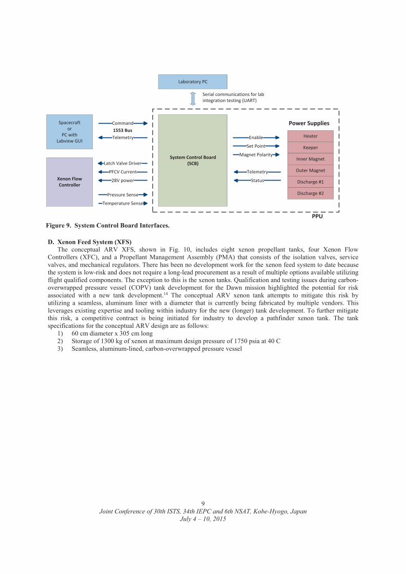
In parallel to the HP-120V PPU development at NASA GRC, a System Control Board (SCB) is under development at JPL to handle the communication with the spacecraft, operate the XFC, control the PPU outputs, and provide fault protection. The system control board is the PPU (and EP string) interface with the spacecraft computer,taking commands and sending status. A prototype SCB has been fabricated and is undergoing functional testing before integration with the HP-120V PPU. A schematic of the system control board interfaces is shown in Fig. 9.
Figure 8. 14kW HP-120/800V Brassboard PPU top-level design including thruster connections.
Joint Conference of 30th ISTS, 34th IEPC and 6th NSAT, Kobe-Hyogo, JapanJuly 4 – 10, 2015
9
D. Xenon Feed System (XFS)The conceptual ARV XFS, shown in Fig. 10, includes eight xenon propellant tanks, four Xenon Flow
Controllers (XFC), and a Propellant Management Assembly (PMA) that consists of the isolation valves, service valves, and mechanical regulators. There has been no development work for the xenon feed system to date becausethe system is low-risk and does not require a long-lead procurement as a result of multiple options available utilizing flight qualified components. The exception to this is the xenon tanks. Qualification and testing issues during carbon-overwrapped pressure vessel (COPV) tank development for the Dawn mission highlighted the potential for risk associated with a new tank development.14 The conceptual ARV xenon tank attempts to mitigate this risk by utilizing a seamless, aluminum liner with a diameter that is currently being fabricated by multiple vendors. This leverages existing expertise and tooling within industry for the new (longer) tank development. To further mitigate this risk, a competitive contract is being initiated for industry to develop a pathfinder xenon tank. The tank specifications for the conceptual ARV design are as follows:
1) 60 cm diameter x 305 cm long2) Storage of 1300 kg of xenon at maximum design pressure of 1750 psia at 40 C3) Seamless, aluminum-lined, carbon-overwrapped pressure vessel
System Control Board (SCB)
Heater
Keeper
Inner Magnet
Outer Magnet
Discharge #1
Power SuppliesSpacecraftor
PC with Labview GUI
Command
Telemetry Enable
Set Point
Telemetry
1553 Bus
Laboratory PC
Serial communications for lab integration testing (UART)
Discharge #2
Magnet Polarity
PPU/DDU
Xenon Flow Controller
Latch Valve Driver
PFCV Current
28V power
Pressure Sense
Temperature Sense
Status
Figure 9. System Control Board Interfaces.

Joint Conference of 30th ISTS, 34th IEPC and 6th NSAT, Kobe-Hyogo, JapanJuly 4 – 10, 2015
10
E. Mechanical Integration Hardware (MIH)The MIH includes structural and thermal hardware integral with IPS elements and cabling between IPS
subsystems and components including structural elements for installing the IPS and heat rejection elements.
IV. System and Acquisition StatusGiven the lead times required for the IPS components, acquisition for most of the major components has been
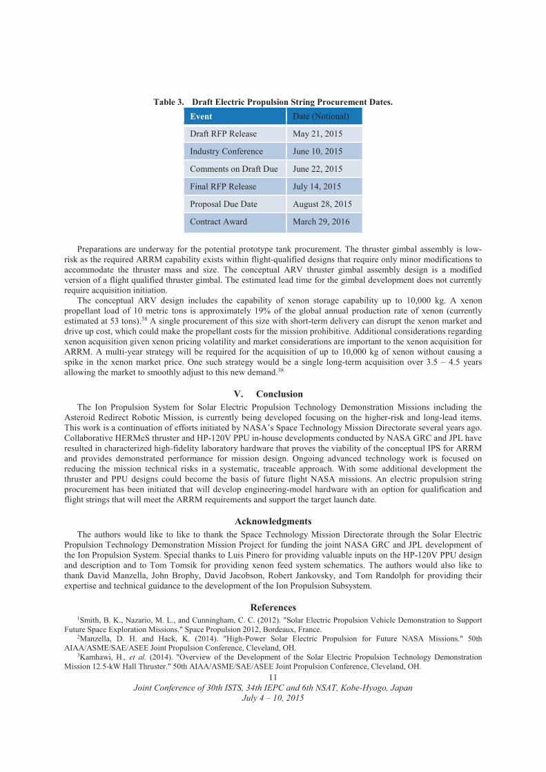
initiated. A draft RFP for an Engineering Development Unit (EDU) EP string and optional Qualification Model (QM) and Flight Model (FM) hardware delivery was released on May 5, 2015.37 This potential procurement includes the thrusters, power processing units, xenon flow controllers, and electric harnesses between the subsystems. A draft of the procurement schedule is shown in Table 3.
Figure 10. Conceptual Asteroid Redirect Vehicle (ARV) Xenon Feed System (XFS) Design.
Joint Conference of 30th ISTS, 34th IEPC and 6th NSAT, Kobe-Hyogo, JapanJuly 4 – 10, 2015
11
Table 3. Draft Electric Propulsion String Procurement Dates.Event Date (Notional)
Draft RFP Release May 21, 2015
Industry Conference June 10, 2015
Comments on Draft Due June 22, 2015
Final RFP Release July 14, 2015
Proposal Due Date August 28, 2015
Contract Award March 29, 2016
Preparations are underway for the potential prototype tank procurement. The thruster gimbal assembly is low-risk as the required ARRM capability exists within flight-qualified designs that require only minor modifications to accommodate the thruster mass and size. The conceptual ARV thruster gimbal assembly design is a modified version of a flight qualified thruster gimbal. The estimated lead time for the gimbal development does not currently require acquisition initiation.
The conceptual ARV design includes the capability of xenon storage capability up to 10,000 kg. A xenon propellant load of 10 metric tons is approximately 19% of the global annual production rate of xenon (currently estimated at 53 tons).38 A single procurement of this size with short-term delivery can disrupt the xenon market anddrive up cost, which could make the propellant costs for the mission prohibitive. Additional considerations regarding xenon acquisition given xenon pricing volatility and market considerations are important to the xenon acquisition for ARRM. A multi-year strategy will be required for the acquisition of up to 10,000 kg of xenon without causing a spike in the xenon market price. One such strategy would be a single long-term acquisition over 3.5 – 4.5 years allowing the market to smoothly adjust to this new demand.38
V. ConclusionThe Ion Propulsion System for Solar Electric Propulsion Technology Demonstration Missions including the
Asteroid Redirect Robotic Mission, is currently being developed focusing on the higher-risk and long-lead items. This work is a continuation of efforts initiated by NASA’s Space Technology Mission Directorate several years ago.Collaborative HERMeS thruster and HP-120V PPU in-house developments conducted by NASA GRC and JPL have resulted in characterized high-fidelity laboratory hardware that proves the viability of the conceptual IPS for ARRMand provides demonstrated performance for mission design. Ongoing advanced technology work is focused on reducing the mission technical risks in a systematic, traceable approach. With some additional development the thruster and PPU designs could become the basis of future flight NASA missions. An electric propulsion string procurement has been initiated that will develop engineering-model hardware with an option for qualification andflight strings that will meet the ARRM requirements and support the target launch date.
AcknowledgmentsThe authors would like to like to thank the Space Technology Mission Directorate through the Solar Electric
Propulsion Technology Demonstration Mission Project for funding the joint NASA GRC and JPL development of the Ion Propulsion System. Special thanks to Luis Pinero for providing valuable inputs on the HP-120V PPU design and description and to Tom Tomsik for providing xenon feed system schematics. The authors would also like to thank David Manzella, John Brophy, David Jacobson, Robert Jankovsky, and Tom Randolph for providing their expertise and technical guidance to the development of the Ion Propulsion Subsystem.
References1Smith, B. K., Nazario, M. L., and Cunningham, C. C. (2012). "Solar Electric Propulsion Vehicle Demonstration to Support
Future Space Exploration Missions." Space Propulsion 2012, Bordeaux, France.2Manzella, D. H. and Hack, K. (2014). "High-Power Solar Electric Propulsion for Future NASA Missions." 50th
AIAA/ASME/SAE/ASEE Joint Propulsion Conference, Cleveland, OH.3Kamhawi, H., et al. (2014). "Overview of the Development of the Solar Electric Propulsion Technology Demonstration
Mission 12.5-kW Hall Thruster." 50th AIAA/ASME/SAE/ASEE Joint Propulsion Conference, Cleveland, OH.
Joint Conference of 30th ISTS, 34th IEPC and 6th NSAT, Kobe-Hyogo, JapanJuly 4 – 10, 2015
12
4Spence, B., et al. (2014). "Technology Maturation and Advancement Update of the ROSA/MegaROSA Solar Array " Space Power Workshop, Huntington Beach, CA.
5Mercer, C. R. and et. al. (2015). "Solar Array Technology Development for Electric Propulsion." Space Power Workshop, Huntington Beach, CA.
6Murphy, D., et al. (2014). "MegaFlex Solar Array Development and Test – Results from Phase 1 of the NASA Game Changing Development (GCD) Program for Solar Electric Propulsion (SEP) Solar Array Systems (SAS) Program." Space Power Workshop, Huntington Beach, CA.
7Kerslake, T. W. (2015). "Advanced Solar Arrays for NASA Electric Propulsion Missions." SciTech 2015, Kissimmee, FL.8Brophy, J. R. and Muirhead, B. (2013). "Near-Earth Asteroid Retrieval Mission (ARM) Study." 33rd International Electric
Propulsion Conference, Washington, DC.9Gates, M. (2015). "NASA's Asteroid Redirect Mission Concept Development Summary." IEEE Aerospace Conference, Big
Sky, MT.10Muirhead, B. and Brophy, J. R. (2014). "Asteroid Redirect Robotic Mission Feasibility Study." Presented at teh IEEE
Aerospace Conference, Big Sky, MT.11Mazanek, D. D., et al. (2014). "Asteroid Redirect Robotic Mission: Boulder Capture Overview Option." 50th
AIAA/ASME/SAE/ASEE Joint Propulsion Conference, Cleveland, OH.12Strange, N., et al. (2013). "Overview of Mission Design for NASA Astreroid Redirect Robotic Mission Concept." 33rd
International Electric Propulsion Conference, Washington, DC.13Dankanich, J. W., Brophy, J. R., and Polk, J. E., "Lifetime Qualification Standard for Electric Thrusters," AIAA-2009-
5095, http://discovery.larc.nasa.gov/PDF_FILES/11_EP_Standard_Disc_Lib_final.pdf, 45th AIAA/ASME/SAE/ASEE Joint Propulsion Conference and Exhibit, Denver, CO, August 2-5, 2009.
14Brophy, J. R., et al., "Development and Testing of the Dawn Ion Propulsion System," AIAA-2006-4319, 42nd
AIAA/ASME/SAE/ASEE Joint Propulsion Conference and Exhibit, Sacramento, CA, July 9-12, 2006.15Brophy, J. R. (2014). "Technology for a Robotic Asteroid Redirect Mission." Presented at teh IEEE Aerospace Conference,
Big Sky, MT.16Hofer, R. R., et al. (2015). "Design Methodology and Scaling of the 12.5 kW HERMeS Hall Thruster for the Solar Electric
Propulsion Technology Demonstration Mission." Presented at the 62nd JANNAF Propulsion Meeting, Nashville, TN.17Mikellides, I., Hofer, R. R., Katz, I., and Goebel, D. M., "Magnetic Shielding of Hall Thrusters at High Discharge
Voltages," Journal of Applied Physics, Vol. 116, No. 5, 053302, 2014.18Kamhawi, H., Manzella, D. H., Smith, T. B., and Schmidt, G. R. (2012). "High-Power Hall Propulsion Development at
NASA Glenn Research Center." Space Propulsion 2012, Bordeaux, France.19Myers, J., Kamhawi, H., and Yim, J. (2015). "HERMeS Thermal Model." 51st AIAA/SAE/ASEE Joint Propulsion
Conference, Orlando, FL.20Lopez Ortega, A., Mikellides, I., and Katz, I. (2015). "Hall2de Numerical Simulations for the Assessment of Pole Erosion
in a Magnetically-Shielded Hall Thruster." 30th International Electric Propulsion Conference, Kobe, Hyogo, Japan.21Kamhawi, H., Haag, T. W., Huang, W., and Hofer, R. R. (2015). "The Voltage-Current Characteristics of the 12.5 kW Hall
Effect Rocket with Magnetic Shielding at Different Background Pressure Conditions." Presented at the 62nd JANNAF Propulsion Meeting, Nashville, TN.
22Kamhawi, H., et al. (2015). "Performance Characterization of the Solar Electric Propulsion Technology Demonstration Mission 12.5-kW Hall Thruster." 30th International Electric Propulsion Conference, Kobe, Hyogo, Japan.
23Hofer, R. R., et al. (2015). "Development Approach and Status of the 12.5 kW HERMeS Hall Thruster for the Solar Electric Propulsion Technology Demonstration Mission." 30th International Electric Propulsion Conference, Kobe, Hyogo, Japan.
24Kamhawi, H., Haag, T., Huang, W., and Hofer, R. R. (2015). "The Voltage-Current Characteristics of the 12.5 kW Hall Effect Rocket with Magnetic Shielding at Different Background Pressure Conditions." 62nd JANNAF Propulsion Meeting, Nashville, TN.
25Kamhawi, H., et al. (2015). "Performance Characterization of the Solar Electric Propulsion Technology Demonstration Mission 12.5-kW Hall Thruster." 34th International Electric Propulsion Conference, Kobe, Japan.
26Myers, J., Kamhawi, H., and Yim, J. (2015). "HERMeS Thermal Model." 51st Joint Propulsion Conference, Orlando, FL.27Goebel, D. M., Polk, J. E., Mikellides, I. G., and Lopez Ortega, A. (2015). "Lanthanum Hexaboride Hollow Cathode for the
Asteroid Retrieval/Redirect Mission " 34th International Electric Propulsion Conference, Kobe, Japan.28Polk, J. E., et al. (2015). "Thermal Characteristics of Lanthanum Hexaboride Hollow Cathodes." 34th International Electric
Propulsion Conference, Kobe, Japan.29Sekerak, M., et al. (2015). "Wear Testing of a Magnetically Shielded Hall Thruster at 2000 s Specific Impulse." 34th
International Electric Propulsion Conference, Kobe, Japan.30Shastry, R., Huang, W., and Kamhawi, H. (2015). "Near-Surface Plasma Characterization of the 12.5-kW NASA TDU1
Hall Thruster." 51st Joint Propulsion Conference, Orlando, FL.31Huang, W., et al. (2015). "Non-Contact Thermal Characterization of NASA’s 12.5-kW Hall Thruster." 51st Joint
Propulsion Conference, Orlando, FL.32Williams, G. J. and Kamhawi, H. (2015). "Optical characterization of component wear and near-field plasma of the
HERMeS thruster." 62nd JANNAF Propulsion Meeting, Nashville, TN.

Joint Conference of 30th ISTS, 34th IEPC and 6th NSAT, Kobe-Hyogo, JapanJuly 4 – 10, 2015
13
33Yim, J. T. and Burt, J. M. (2015). "Characterization of vacuum facility background gas through simulation and considerations for electric propulsion ground testing." 51st Joint Propulsion Conference, Orlando, FL.
34Shastry, R., Huang, W., and Kamhawi, H. (2015). "Near-Surface Plasma Characterization of the 12.5-kW NASA TDU1 Hall Thruster." To be Presented at the 51st AIAA/SAE/ASEE Joint Propulsion Conference, Orlando, FL.
35Huang, W., et al. (2015). "Non-Contact Thermal Characterization of NASA’s 12.5-kW Hall Thruster." To be Presented at the 51st AIAA/SAE/ASEE Joint Propulsion Conference, Orlando, FL.
36Pinero, L. R., et al. (2015). "Development of High-Power Hall Thruster Power Processing Units at NASA GRC." 51st AIAA/SAE/ASEE Joint Propulsion Conference, Orlando, FL.
37NNC15ZCH014R, S. N. (2015). "https://prod.nais.nasa.gov/cgibin/eps/synopsis.cgi?acqid=165360." Cleveland, OH.38Herman, D. A. and Unfried, K. G. (2015). "Xenon Acquisition Strategies for High-Power Electric Propulsion NASA
Missions." Presented at the 62nd JANNAF Propulsion Meeting, Nashville, TN.


