The Intrinsically Safe High Power Trunk - Fieldbus · Validating of intrinsic safety ... The...
26
1 The Intrinsically Safe High Power Trunk Thomas Klatt Pepperl+Fuchs GmbH Business Development Manager E-mail: [email protected] Phone: +49 621 776 2130 Multaqa 2011, Abu Dhabi
Transcript of The Intrinsically Safe High Power Trunk - Fieldbus · Validating of intrinsic safety ... The...
1
Multaqa 2011,
Abu Dhabi, VAE
© 1994 – 2011 Fieldbus Foundation
The Intrinsically Safe
High Power Trunk
Thomas Klatt
Pepperl+Fuchs GmbH
Business Development Manager
E-mail: [email protected]
Phone: +49 621 776 2130
Multaqa 2011, Abu Dhabi

2
Multaqa 2011,
Abu Dhabi, VAE
© 1994 – 2011 Fieldbus Foundation
Agenda
Developments of fieldbus in hazardous area
application
Purpose of the new concept
Topology of an intrinsically safe high power trunk
Technical values
Validating of intrinsic safety
Conclusion
3
Multaqa 2011,
Abu Dhabi, VAE
© 1994 – 2011 Fieldbus Foundation
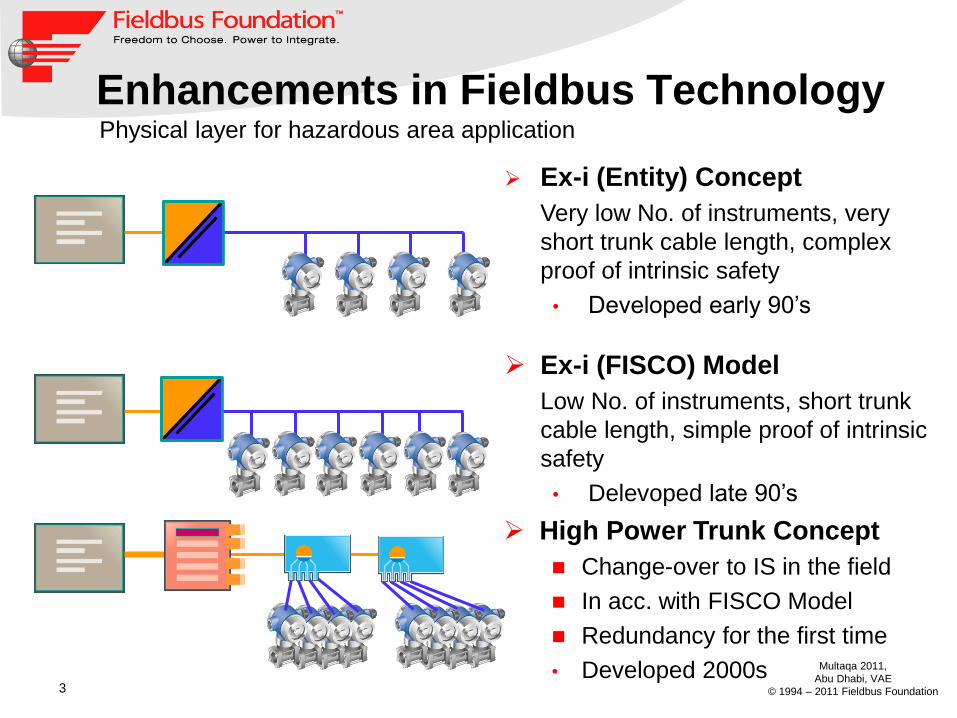
Enhancements in Fieldbus Technology
Ex-i (Entity) Concept
Very low No. of instruments, very
short trunk cable length, complex
proof of intrinsic safety
• Developed early 90’s
Ex-i (FISCO) Model
Low No. of instruments, short trunk
cable length, simple proof of intrinsic
safety
• Delevoped late 90’s
High Power Trunk Concept
Change-over to IS in the field
In acc. with FISCO Model
Redundancy for the first time
• Developed 2000s
Physical layer for hazardous area application

4
Multaqa 2011,
Abu Dhabi, VAE
© 1994 – 2011 Fieldbus Foundation
Limitation of Full FISCO

5
Multaqa 2011,
Abu Dhabi, VAE
© 1994 – 2011 Fieldbus Foundation
Purpose of a new concept
Provide a choice combining
FISCO's Simplicity of intrinsic safety with the
Benefits of the High-Power Trunk:
Cable distance
High device count
Real power supply redundancy with load
sharing

6
Multaqa 2011,
Abu Dhabi, VAE
© 1994 – 2011 Fieldbus Foundation
Realization of IS today (simplified)
In case the input voltage is too high the Zener-diode becomes
conductive and the fuse will blow
The Zener-diode limits the max. voltage available to the field
The resistor limits the max. current available in the field
This is a power limitation
Sparks will be avoided
IS today
Fie
ld
sid
e

7
Multaqa 2011,
Abu Dhabi, VAE
© 1994 – 2011 Fieldbus Foundation
Basic idea
Ignition requires energy
Energy for gas ignitions is well known
E.g. Hydrogen 20 µJ resp. 20 µWs
Energy is
tIUW ** for DC signals
dttitutw )(*)()( for AC signals
Today the time is not considered in intrinsic
safety

8
Multaqa 2011,
Abu Dhabi, VAE
© 1994 – 2011 Fieldbus Foundation
Basic idea
Interrupt the flow of power when energy
escapes the electric circuit

9
Multaqa 2011,
Abu Dhabi, VAE
© 1994 – 2011 Fieldbus Foundation
Simple Circuit
Ex ib IIC
Time to turn-off: 5 to 10 µs

10
Multaqa 2011,
Abu Dhabi, VAE
© 1994 – 2011 Fieldbus Foundation
Typical Spark – Physics
IF
UF
PF
Initial
Phase Critical Phase
Spark duration tF: long t
U, I,
P
di/dt
Investigated by PTB

11
Multaqa 2011,
Abu Dhabi, VAE
© 1994 – 2011 Fieldbus Foundation
Typical Spark – Turned off
IF
UF
PF
Initial
Phase Critical Phase
Spark duration with Power-i tF (small)
U, I,
P
t
Investigated by PTB

12
Multaqa 2011,
Abu Dhabi, VAE
© 1994 – 2011 Fieldbus Foundation
The Power Supply – Block Diagram
S1
Rstart
V VO
I-
Detector
overcurrent
+di-
Detector
-di-
Detector
undervoltage
break spark make spark
Monoflop

13
Multaqa 2011,
Abu Dhabi, VAE
© 1994 – 2011 Fieldbus Foundation
U
I
X
Output characteristic Power Supply
1 Power Off
2 Initial On – S1 open
3 Threshold – S1 closes
4 Overload condition
Turning On
1 2
3
4
RL1
RL2 Ulim
Uthres
Ilim

14
Multaqa 2011,
Abu Dhabi, VAE
© 1994 – 2011 Fieldbus Foundation
U
I
X
Output characteristic Power Supply
Turning Off RL1
RL2 Ulim
Uthres
1
1 Switch S1 will
open in ≤ 2 µs
2 Provided power is
below the limits
safe status
2

15
Multaqa 2011,
Abu Dhabi, VAE
© 1994 – 2011 Fieldbus Foundation
General Purpose Area
Zone 2 To DCS
Zone 1
Intrinsically safe High-Power Trunk
Redundant, three-port isolated
I.S. HPT Power Supply
I.S. HPT Segment Protectors
The intrinsically safe High-Power Trunk
protected by Power-i/DART
Intrinsically safe spurs
“conventional IS”
Ex ib IIC

16
Multaqa 2011,
Abu Dhabi, VAE
© 1994 – 2011 Fieldbus Foundation
Overview – Intrinsic Safety
In an I.S. High Power Trunk fieldbus application only
the TRUNK is protected by the new technology
Today's intrinsically safe field devices and standard
H1 controllers are supported!

17
Multaqa 2011,
Abu Dhabi, VAE
© 1994 – 2011 Fieldbus Foundation
Comparison of Technical Data
FISCO
I.S. High
Power
trunk
High Power
trunk
Rating Ex ia IIC Ex ib IIC Ex ib IIB Ex ib IIC
Typ.
operating
voltage
12.8 V 12.4 V 13.1 V 22 V 28 V
Max. supply
current 100 mA 120 mA 265 mA 360 mA 500 mA
Compared to the FISCO solutions I.S. High Power Trunk
provides
More voltage longer cable runs
More current more instruments per segment

18
Multaqa 2011,
Abu Dhabi, VAE
© 1994 – 2011 Fieldbus Foundation
Overview
I.S. High Power Trunk fieldbus
Supports trunk/spur topology
Allows up to 4 segment protectors per segment
– The limitation of IEC 61158-2 applies to IS HPT fieldbus as
well (32 communication elements per segment)
The overall cable length is limited to 1900 m
– Limitation is coming from IEC 61158-2
The trunk cable length is limited to 1000 m
– Limitation is coming from I.S. requirements
The spur cable length is limited to 120 m
– Limitation is coming from IEC 61158-2

19
Multaqa 2011,
Abu Dhabi, VAE
© 1994 – 2011 Fieldbus Foundation
I.S. High Power Trunk Fieldbus Segment
IS HPT FBPS protects the trunk
Extinguishes a spark before it becomes
incendive
Live disconnect permitted without hot work
permit
Power redundancy with load sharing
Intrinsically Safe Outputs
IS HPT wiring block:
For any existing standard fieldbus
instrument complying to the safety
parameter requirements
Short-circuit protection
=> Intrinsically Safe Ex ib IIC

20
Multaqa 2011,
Abu Dhabi, VAE
© 1994 – 2011 Fieldbus Foundation
IS HPT Fieldbus Power Supply
Redundant Power Supply with load
sharing
With Advanced Diagnostic Module
Works as I.S. Barrier with three-
way galvanic isolation of DCS,
bulk power and fieldbus segment
Technical Data
Trunk Output
Power-i/DART
Fieldbus Power
Supply
Rated power 22 V / 360 mA
DCS supply 10.2 V / 40 mA
Max.trunk cable length 1000 m

21
Multaqa 2011,
Abu Dhabi, VAE
© 1994 – 2011 Fieldbus Foundation
IS HPT Wiring Block
Connections for field instrument
Outputs intrinsically safe Ex ib IIC
With short-circuit protection
Live disconnect on trunk and spurs
Technical Data
IS HPT
wiring block
Rated power (spur) min 10.5 V @ 34 mA
IS Power rating
Trunk
Only for connection to IS HPT fieldbus
power supply
Spur (Uo / Io) 23 V / 47 mA
Spur length
(acc. to
IEC 61158 -2)
120 m (1 – 12 communication elements)
90 m (13 – 14 communication elements)
60 m (15 – 18 communication elements)
30 m (19 – 24 communication elements)

22
Multaqa 2011,
Abu Dhabi, VAE
© 1994 – 2011 Fieldbus Foundation
Validating Intrinsic Safety
Four certificates will be required
Certificate for the for the I.S. fieldbus power supply
Certificate for the Motherboard of FBPS
Certificate for the Power-i/DART wiring block
System approval

23
Multaqa 2011,
Abu Dhabi, VAE
© 1994 – 2011 Fieldbus Foundation
Validating Intrinsic Safety
On the Trunk – As fast as easy
Use only type 'A' fieldbus cable
Ensure trunk cable length is max. 1000 m
Use only IS HPT fieldbus power supplies and IS HPT
Segment Protectors according to the certificate
That's All! – Easy to understand, easy to engineer.
Certified ATEX and IECEx acc. to IEC 60079-11

24
Multaqa 2011,
Abu Dhabi, VAE
© 1994 – 2011 Fieldbus Foundation
<
Status of
Certification

25
Multaqa 2011,
Abu Dhabi, VAE
© 1994 – 2011 Fieldbus Foundation
About the Spurs

26
Multaqa 2011,
Abu Dhabi, VAE
© 1994 – 2011 Fieldbus Foundation
Conclusion
The intrinsically safe High-power Trunk Concept…
Is certified in acc. with international standards (IEC 60079-11)
Support today's intrinsically safe instruments
Provides higher power (compared to FISCO) for
– Longer cable runs
– More instruments per segment
Features power supply redundancy with load sharing
Permits validation of I.S. without calculations
… is a solution for applications where the trunk is
required to be intrinsically safe


![Leak detector for systems containing liquids for tanks used to …€¦ · Intrinsically safe II (1) G [EEx ia] II C NOT intrinsically safe LAG 2000 B complete Intrinsically safe](https://static.fdocuments.net/doc/165x107/60514f65857747156b588f31/leak-detector-for-systems-containing-liquids-for-tanks-used-to-intrinsically-safe.jpg)