The international publication for Offshore & Marine … · propulsion and automation system on...
68
The international publication for Offshore & Marine Technology | 2012 www.shipandoffshore.net Offshore frontiers: Exploration in harsh environments 44 Surface technology: Hydrodynamic effects of biofilms 20 Innovative vessels: Versatile designs for RoRo carriers 10 June № 4 04 | 12
Transcript of The international publication for Offshore & Marine … · propulsion and automation system on...

The international publication for Offshore & Marine Technology
| 2012
www.shipandoffshore.net
��Off shore frontiers: Exploration in harsh environments 44
��Surface technology: Hydrodynamic eff ects of biofi lms 20
��Innovative vessels: Versatile designs for RoRo carriers 10
June№ 4
04
| 12
SPI_004-12_1_2_20120514125303_504946.indd 1 14.05.2012 12:53:18
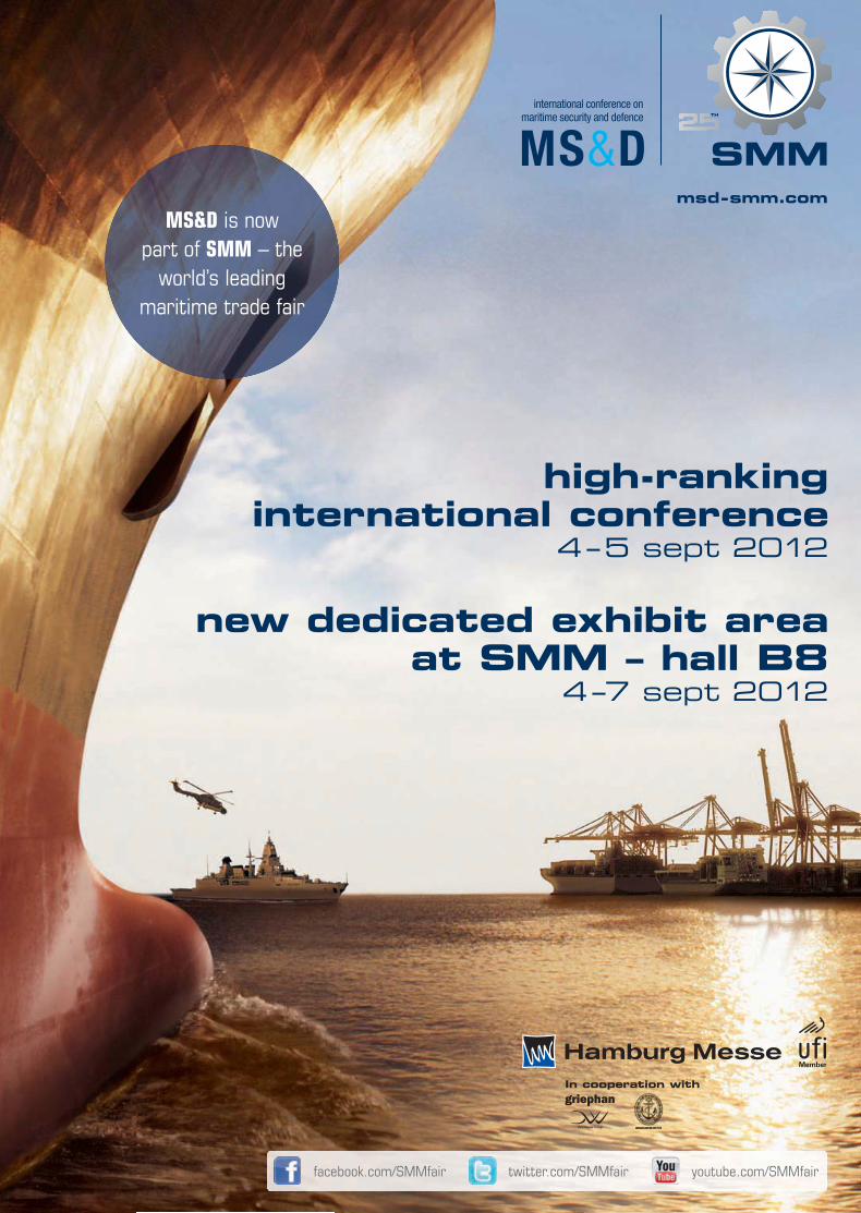
msd-smm.comMS&D is now
part of SMM – the world’s leading
maritime trade fair
high-ranking international conference
4 – 5 sept 2012
new dedicated exhibit area at SMM – hall B8
4 – 7 sept 2012
In cooperation with
facebook.com/SMMfair twitter.com/SMMfair youtube.com/SMMfair
SPI_004-12_1_2_20120514125303_504946.indd 2 14.05.2012 12:53:21
Offshore wind energy – a rapidly growing marketOffshore wind energy is a dynamic, rapidly growing busi-ness sector offering attractive opportunities to all segments of the maritime industry. Ports provide logistical support for wind farms, shipyards build the special ships that are needed, shipping companies manage the installation and service vessels, and sup-pliers supply essential technologies. In its recent global offshore wind report, UK-based energy business advisors Douglas-West-wood forecast that more than 11 GW of new capacity would be installed worldwide by 2015. Europe is playing a leading role.But many challenges must be overcome before wind energy pro-viders’ ambitious goals can be realised. Grid connections must be secured, electricity storage technologies developed, safety concepts improved and fi nancial gaps fi lled. What is more, the construction and operation of wind energy facilities must be reliable, environ-mentally acceptable and economically sound. To accomplish these things, the experience and know-how of the offshore oil and gas sector should be utilised. Solutions to some of the most pressing problems at present are advanced in this issue of Ship&Offshore.On page 34, The Boston Consulting Group takes a business look at electricity storage of fl uctuating renewable energy such as offshore wind. Its assessment of the possibilities is optimis-tic. The article on page 38 describes how the increasing size of offshore wind turbines – and the monopiles that support them in ever deeper waters – affects the outfi tting of vessels used in transport, lifting and installation operations. A promising safe-ty measure meant to prevent ships from crashing into offshore wind farms or other marine structures is proposed on page 40.The global signifi cance of offshore wind energy is refl ected in a number of noteworthy events this year. Organisers of the 31st International Conference on Ocean, Offshore and Arctic Engi-neering (OMAE 2012) in Rio de Janeiro from July 1st to 6th – during which more than 800 technical papers are planned for presentation – are giving it high priority alongside their tra-ditional areas of focus. And Germany will hold its fi rst offshore wind energy fair and most important offshore conference, called Windforce 2012, from June 26th to 29th in Bremen.
Another challenging, fast-growing offshore market is gas and oil exploration and extraction in harsh conditions such as deep water and especially ice. In the article on page 44, Henrik Hannus and Per Kristian Bruun, from Norway’s Aker Solutions, describe interesting new technologies and holistic solutions in this fi eld. FPSO (fl oating production, storage and offl oading) units used in Brazilian oil fi elds face demanding environments and operational diffi culties. The sophisticated FPSO Maersk Peregrino, which was converted from the VLCC tanker Maersk Nova, is presented on page 28. Thanks to the large deposits found in its waters, Brazil is expected to become one of the world’s top fi ve oil producers by 2020. This rapid expansion will require major efforts from the country’s petro-leum industry. On page 46 is a summary of the strict liability regime infl uencing hiring requirements for offshore profes-sionals there.Although the shipbuilding market continues to struggle with weak demand, diffi cult fi nancing conditions and structural imbalances amid global overcapacity, there are nevertheless newbuilding projects worthy of mention. On page 10, our “Innovative Vessels” series introduces some remarkable designs for RoRo carriers. Design is also the subject of the article on page 18, which focuses on the electrical components of the propulsion and automation system on board South Africa’s Antarctic research and supply vessel S.A. Agulhas II.Any way to improve a ship’s hydrodynamic effi ciency – and consequently its operational cost effi ciency – is highly wel-come. On page 20 is a comprehensive overview of the latest fi ndings on the relationship between biofouling and ship re-sistance. A related topic, namely the effects of a rough propel-ler on a vessel’s fuel consumption, is the subject of the article on page 24.Finally, we’d like to draw readers’ attention to the international shipping exhibition Posidonia, to be held in Athens from June 4th to 8th. It is expected to be a lively meeting place for the inter-national shipping and shipbuilding community. See page 32.
Ship & Offshore | 2012 | No 4 3
COMMENT
Dr.-Ing. Silke SadowskiEditor in Chief
SPI_004-12_3_3_20120514125403_504945.indd 3 14.05.2012 12:54:25
� Offshore & Marine Technology
10
Corrosion protection & surface technology
26 Protective coatings pass tests
27 Wet abrasion scrub tester
27 Bio-fouling control
Ship repair & conversion28 Sophisticated FPSO unit for
Brazilian oil fi eld
Industry news32 Shipping to support economy
32 Defi nition and management of pipe supports
33 Life jacket light
33 Launch of tube and pipe weld purge systems
� Shipbuilding & Equipment
� Shipbuilding & Equipment
� In Focus Renewable energy
Innovative vessels10 Versatile RoRo ship designs
Green ship technology14 Advanced waste fuel
recovery system introduced
Propulsion & manoeuvring technology
18 Propulsion concept for research and supply vessel
Corrosion protection & surface technology
20 Hydrodynamic effects
24 Propeller maintenance
Renewable energy34 Sector with a bright future
37 Jack-up barge crane
37 Wind turbine project
38 Analysis of lifting operations at offshore wind farms
40 Improved safety for offshore wind farms
42 Offshore conference with fi rst-time trade fair
43 Cooperation aimed at improving wind turbines
Professional Publications for Shipping, Marine and Off shore Technology
www.shipandoffshore.net
��Simulator: „Safety and Security“-Trainer
��Beschreibung: Forschungsschiff „S.A. Agulhas II“
��Rückblick 2011: Ablieferungen deutscher Werften
|
������������� �� ������������������������ �� ��������������������������������� �� ����
��� �������� ���������������������� ��������������������������
www.shipandoffshore.net
The international publication for Offshore & Marine Technology
�� 22
�� 74
�� 42
| |
AZIMUT BENETTI
SOLUTIONS THAT SPAN THE MARINE INDUSTRY
SPI_004-12_4_5_20120514130104_504944.indd 4 14.05.2012 13:01:20
6446
� Industry news66 Pinpoint positioning improves
cargo handling productivity
66 Call for EU tonnage tax stability
� Green shipping63 Cost savings by measuring
bunker fuel accurately
63 Route to a more sustainable industry
Navigation & communication
64 Enhanced ECDIS launched
64 Global C/Ku VSAT system introduced
64 INS type approval for bridge control system
� Offshore & Marine Technology
� Ship Operation
� Ship Operation
� RegularsCOMMENT ........................... 3NEWS & FACTS ................... 6BUYER‘S GUIDE ................ 51IMPRINT ............................. 67
Oil & gas44 Offshore frontiers
Human resources46 Need for investment in
training and education
Industry news48 Rig type for increased oil recovery
48 Jack-up classifi cation
48 Stern-fi rst navigation
50 Crane system delivered
50 Introduction of effi ciency-enhancing solutions
FIL-TEC Rixen GmbHOsterrade 26 • D-21031 Hamburg
Tel. +49 (0)40 656 856-0Fax +49 (0)40 656 57 31
The specialists for filter-technology for shipping and industrial applications for 25 yearsAs specialist for filter Fil-Tec Rixen GmbH has been successful with the improvement and the production
as well as service and sales of filters and their inlets for shipping and industrial applications.
CONTENT | JUNE 2012
SPI_004-12_4_5_20120514130104_504944.indd 5 14.05.2012 13:01:35

Order for dual-fuel engines LNG carriers | The engine manu-facturer MAN Diesel&Turbo SE will equip several LNG carriers for the Russian shipowner Sov-comfl ot. The newbuilding pro-gramme comprises two vessels with an option for two more.The vessels are currently under construction at STX Offshore & Shipbuilding in South Korea. They will be driven by sets of two 8L and two 9L51/60DF en-gines each.Sovcomfl ot selected the dual-fuel MAN 51/60DF engine for all units to provide the vessels with a high-effi ciency and low-emissions propulsion system, especially when running in gas mode, according to MAN. A high degree of redundancy and the MAN 51/60 DF engine’s multiple fuelling options have also been taken into account. The engines will be built at
MAN Diesel & Turbo’s Augs-burg plant in Germany with expected delivery to the South Korean yard in the fourth quar-ter of 2012. The fi rst vessel is expected to commence com-mercial operation in the fourth quarter of 2013.
Fire-fi ghting vessel deliveredBremen 1 | Damen Shipyards recently delivered a 2406-type fi re-fi ghting vessel (FFV) to the city of Bremen, Germany. Called the Bremen 1, it has an overall length of 23.9m, a breadth of 6m, and a draught of 1.2m. Three main engines – two CAT C12 type with a capacity of 425 kW each and one CAT C18 type with a capacity of 651 kW – provide power for a maximum speed of about 21 knots.
In addition, three water-jets and a 45 kW single bow thruster ensure the ship’s ma-noeuvrability. The newbuilding is equipped with a large fi re pump, which has a capacity of 14,000 l/min at 10 bar. A second and smaller pump of 1,000 l/min is also installed. The Bremen 1 uses a mixture of water and foam to extinguish fi res. It replaces its predecessor, built in 1975.
Order for second heavy-lift vesselK-3000 | Jumbo Shipping has confi rmed the order for a second K-class vessel, with an option for a third, to complement its existing fl eet.The heavy-weight cargo transportation company says it has decided to upgrade the lifting capac-ity of the vessels from 1,300 to 1,500t, enabling tandem lifts of 3,000t. The new vessels are said to comfortably surpass the capability of other vessels in their class. They are being built at the Brodosplit shipyard in Split, Croatia. The design incorporates Finnish-Swedish ice class 1A.
Each vessel will be prepared for DP2 instal-lation, which will provide multi-faceted in-stallation support in the offshore sector, ena-bling large and heavy structures to be loaded, transported and installed by a single vessel, optimising project scheduling, safety and ef-fi ciency. The fi rst vessel will enter into service in autumn 2013. Its sistership will follow some six months later. Jumbo Shipping says that this latest investment underlines the company’s long-term commitment to its existing and new clients.
Artist‘s impression of the new K-3000 vessel
Walking jack-up barge developedWaveWalker 1 | Fugro, special-ised in the collection and inter-pretation of research data, and dredging and marine contrac-tor Van Oord, have announced their joint development of a large walking jack-up barge.The two Dutch companies are working together on the de-sign, construction and opera-tion of the jack-up, which will start drilling and blasting works in Brazil’s Suape outer channel later this year. It can be oper-ated in a conventional four-legged mode, or as an eight-legged self-contained walking jack-up platform. Undertaking geotechnical site investigations, drilling and other underwater activity from a stable platform with the added benefi t of relo-cation without fl oating is said to reduce the impact of sea con-ditions during the operational hours required for the Brazilian operations and in other harsh coastal zones.
Bremen‘s police and fi re brigade will use the new FFV
Graphical rendering of one of the LNG carriers for Sovcomfl ot
6 Ship & Offshore | 2012 | No 4
INDUSTRY | NEWS & FACTSINDUSTRY | NEWS & FACTS
SPI_004-12_ _9_20120514132 04_504943.indd 14.05.2012 13:33:23

AHTS | A naming ceremony for two an-chor handling tug supply (AHTS) vessels for France-based service provider Bourbon was recently held at the Sinopacifi c Zhe-jiang shipyard in China. The Bourbon Lib-erty 254, which is the last of the Bourbon Liberty 200 series of 54 AHTS vessels, and the Bourbon Liberty 301, the fi rst of the 300 series of 20 AHTS vessels, are both part of the “Bourbon 2015 Leadership Strategy”. All vessels of the Liberty series have been developed for customers in the oil and gas industry. According to Bourbon, they offer great reliability due to a new design and equipment redundancy, excellent
manoeuvrability and low fuel consump-tion. “Bourbon Liberty 300 vessels are the exten-sion of Bourbon Liberty 200 vessels. They provide clients with a larger deck space and the capacity to carry more liquid mud and bulk products. At the same time, they use the same key features as the Bourbon Liber-ty 200 series like 2 DP system, main gensets and azimuth thruster,” said Olivier Daniel, Bourbon’s newbuilding managing director.Nineteen other Bourbon Liberty 300 ves-sels and 15 Bourbon Liberty 150 vessels will join the recently delivered Bourbon Liberty vessels in the near future.
Contract for AHTSSTX OSV | Norway-based STX OSV Hold-ings Limited said it had secured a new contract to design and construct an anchor handling tug supply (AHTS) vessel for the investment company Iceman AS.The designer and builder of offshore and specialised vessels said the newbuilding of type AH 12 will be equipped for multi-role operations in harsh and arctic areas. It will be built according to ice class. The hull of the 94m-long and 24m-wide AHTS will be built by STX OSV in Romania. Delivery of the vessel is scheduled for mid-2013 in Norway.
Naming ceremonyBoth Liberty vessels at the shipyard
Illustration of the AHTS built for Iceman AS
WE UNDERSTAND
MARINE SEWAGE TREATMENT
The OMNIPURE™ Series 55 sewage treatment
systems provide safe and effective treatment of gray
and black water while eliminating the requirement to
handle waste solids from raw, untreated influent.
- Easy to install, operate and service
- Lightweight package
- Minimal maintenance
- No additional tanks or filtration equipment required
- Operates on-demand, instantaneous on-off operation
- Operator-safe solids handling system
- Small equipment footprint
To put our marine sewage treatment systems to work for you
contact [email protected] or visit www.severntrentdenora.com
Ship & Offshore | 2012 | No 4 7
SPI_004-12_ _9_20120514132 04_504943.indd 14.05.2012 13:33:31
Increasedfocus on the Arctic
Oil and gas | Det Norske Veritas (DNV) says it will increase its focus on oil and gas operations in arctic regions in the future. Having acquired the oil-spill preparedness company Nor-wegian Petro Services (NPS), the classifi cation society aims to combine its environmental risk and oil spill preparedness analyses with NPS’s specialist expertise in planning and or-ganising oil-spill preparedness. Since oil and gas operations in the Arctic hold several new risk elements, such as longer distances, cold climate and in-suffi cient infrastructure, DNV says it wants to improve the prevailing safety level in order to reduce the likelihood of an accidental oil spill.
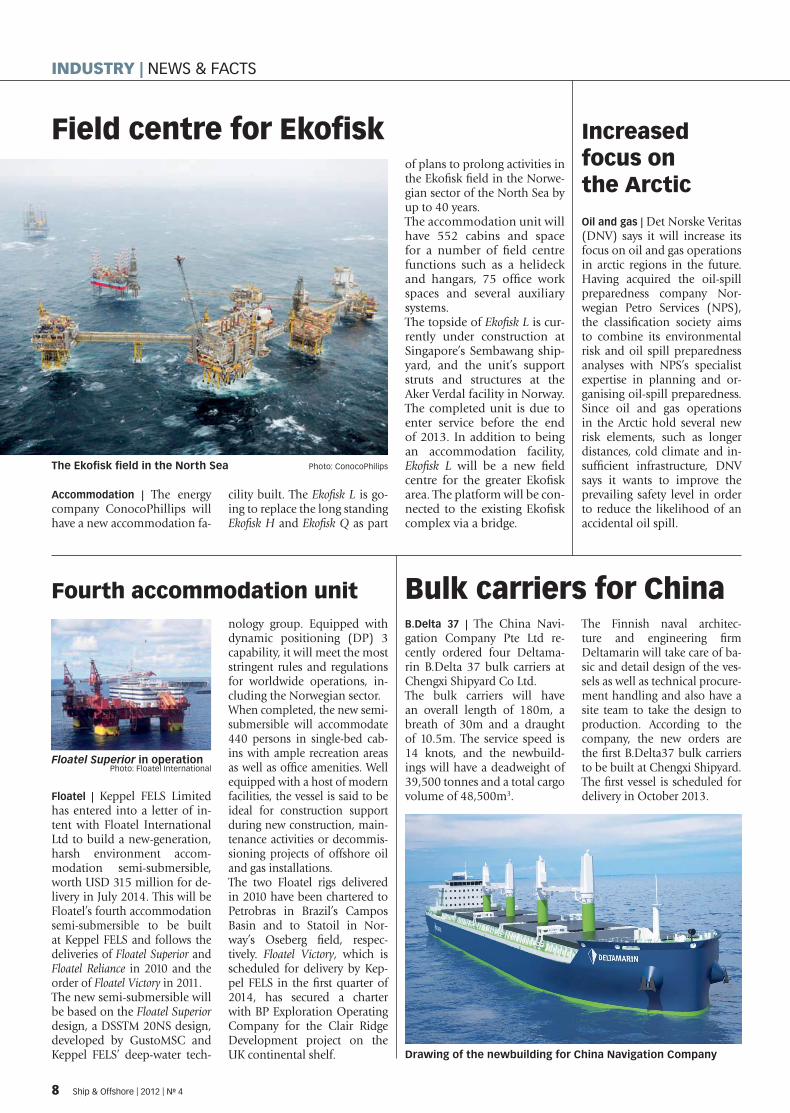
Field centre for Ekofi sk
Accommodation | The energy company ConocoPhillips will have a new accommodation fa-
cility built. The Ekofi sk L is go-ing to replace the long standing Ekofi sk H and Ekofi sk Q as part
of plans to prolong activities in the Ekofi sk fi eld in the Norwe-gian sector of the North Sea by up to 40 years.The accommodation unit will have 552 cabins and space for a number of fi eld centre functions such as a helideck and hangars, 75 offi ce work spaces and several auxiliary systems.The topside of Ekofi sk L is cur-rently under construction at Singapore’s Sembawang ship-yard, and the unit’s support struts and structures at the Aker Verdal facility in Norway. The completed unit is due to enter service before the end of 2013. In addition to being an accommodation facility, Ekofi sk L will be a new fi eld centre for the greater Ekofi sk area. The platform will be con-nected to the existing Ekofi sk complex via a bridge.
Fourth accommodation unit
Floatel | Keppel FELS Limited has entered into a letter of in-tent with Floatel International Ltd to build a new-generation, harsh environment accom-modation semi-submersible, worth USD 315 million for de-livery in July 2014. This will be Floatel’s fourth accommodation semi-submersible to be built at Keppel FELS and follows the deliveries of Floatel Superior and Floatel Reliance in 2010 and the order of Floatel Victory in 2011.The new semi-submersible will be based on the Floatel Superior design, a DSSTM 20NS design, developed by GustoMSC and Keppel FELS’ deep-water tech-
nology group. Equipped with dynamic positioning (DP) 3 capability, it will meet the most stringent rules and regulations for worldwide operations, in-cluding the Norwegian sector.When completed, the new semi-submersible will accommodate 440 persons in single-bed cab-ins with ample recreation areas as well as offi ce amenities. Well equipped with a host of modern facilities, the vessel is said to be ideal for construction support during new construction, main-tenance activities or decommis-sioning projects of offshore oil and gas installations. The two Floatel rigs delivered in 2010 have been chartered to Petrobras in Brazil’s Campos Basin and to Statoil in Nor-way’s Oseberg fi eld, respec-tively. Floatel Victory, which is scheduled for delivery by Kep-pel FELS in the fi rst quarter of 2014, has secured a charter with BP Exploration Operating Company for the Clair Ridge Development project on the UK continental shelf.
Bulk carriers for ChinaB.Delta 37 | The China Navi-gation Company Pte Ltd re-cently ordered four Deltama-rin B.Delta 37 bulk carriers at Chengxi Shipyard Co Ltd.The bulk carriers will have an overall length of 180m, a breath of 30m and a draught of 10.5m. The service speed is 14 knots, and the newbuild-ings will have a deadweight of 39,500 tonnes and a total cargo volume of 48,500m3.
The Finnish naval architec-ture and engineering fi rm Deltamarin will take care of ba-sic and detail design of the ves-sels as well as technical procure-ment handling and also have a site team to take the design to production. According to the company, the new orders are the fi rst B.Delta37 bulk carriers to be built at Chengxi Shipyard.The fi rst vessel is scheduled for delivery in October 2013.
Drawing of the newbuilding for China Navigation Company
The Ekofi sk fi eld in the North Sea Photo: ConocoPhilips
Floatel Superior in operation Photo: Floatel International
8 Ship & Offshore | 2012 | No 4
INDUSTRY | NEWS & FACTS
SPI_004-12_ _9_20120514132 04_504943.indd 14.05.2012 13:33:53

New branch | Global Mari-time has announced the opening in hamburg, Ger-many, of a new branch to their global network. The of-fi ce will serve alongside the 14 other offi ces in the GM group, offering expertise consultancy in the fi elds of assurance, design and con-tracting.
Merger agreement | Istan-bul-based Desan Shipyard and Yardgem Shipyard have entered into a merger agree-ment and will now jointly op-erate under the name Desan Yardgem United Shipyards.
Opening | The shipbuild-ing company Austal has announced the opening of a marine support base in Henderson, Western Austral-ia. The new support base has an area of 11,200m².
New office | The Nether-lands-based dredging and mining vessels builder IHC Merwede recently opened a new offi ce in Singapore. It is to be the cooperate headquarters for IHC off-shore and marine business-es in Southeast Asia as the company wants to further expand its presence in the region.
Initiative | The classi-fi cation society Bureau Veritas has joined forces with French maritime se-curity consultants Secury-mind to provide an auditing and verifi cation service for companies providing armed guards to protect ships against piracy.
LNG bunkering | The Maritime and Port Author-ity of Singapore (MPA) has announced establish-ment of a joint industry project to investigate the oerational feasibility of LNG bunkering in Singapore. The project is being con-ducted in collaboration with the Clean Technology Centre of the classifi cation society Det Norske Veritas and 21 industry partners.
IN BRIEF �
X-series port-folio extended Low-speed engine | Wärtsilä has announced the extension of its low-speed X-generation engine series to the upper end of its portfolio with the 920mm-bore Wärtsilä X92. The new engine will serve the market for large and ultra-large container vessels with a size above 8,000 TEU to any size under construc-tion and beyond. The fi rst 92-bore engine is planned for de-livery in 2014.The engine is designed based on known and validated con-cepts and employs well-proven Wärtsilä electronically control-led common-rail technology. Thanks to these technologies, the X92 is said to be very effi -cient in terms of fuel consump-tion and emissions. Fuel sav-ings of up to 10% and more are expected compared to today’s fl eet, according to the company. The RPM and power range offer fl exibility for a wide variety of vessel speeds. X-series engines feature an extra-long stroke and reduced engine rev-olutions allowing a larger pro-peller diameter.
Hydrographic SWATHJakob Prei | The German ship-yard Abeking & Rasmussen (A&R), based in Lemwerder on the Weser River, recently de-livered a hydrographic survey vessel to the Estonian Maritime Administration.The GL-classed small wa-terplane area twin hull ship (SWATH) Jakob Prei has an over-all length of 25.65m, a breadth of 13m and a draught of 2.7m. Its entire hull was built of alu-minium. Two MAN D 2842 diesel engines, with a capacity of 809 kW each, provide power for a maximum speed of about
20 knots. At a survey speed of 12 knots, the SWATH is said to have a range of approximately 1,000 nm. The survey vessel offers accom-modation and common rooms for eight persons. Furthermore, it is equipped with container-ised installations for research equipment, such as a multi-beam echo sounder, a sub-bot-tom profi ler, a sound velocity probe and a side scan sonar. The Jakob Prei will be employed within the framework of the project “Enhancing Maritime Safety on Estonian Waterways”.
The Jakob Prei was built for the Estonian Maritime Administration
Delivery of multi-purpose vesselLewek Andes | The multi-purpose offshore vessel Lewek Andes was recently delivered to her Singa-porean owner EMAS. It was built by Poland-based Remontowa Shipbuilding SA, the former Northern Shipyard, which was renamed in 2011 and now spe-
cialises on the construction of new vessels. The 87.9m-long and 18.8m-wide vessel, with a deadweight of 5,232 tonnes, is one of two newbuildings for EMAS and will operate off the western coast of Africa. The DP-2 vessel has a deck area of
790m2 and offers accommoda-tion for up to 60 people. Lewek Andes has been designed to service drilling units and sup-port production platforms with safety standby, seismic opera-tions and emergency evacua-tion capabilities.
The Lewek Andes will be deployed off West Africa
Ship & Offshore | 2012 | No 4 9
SPI_004-12_ _9_20120514132 04_504943.indd 9 14.05.2012 13:34:10

CARGO CARRIERS The transport of large numbers of cars is one of the most effi cient uses of RoRo (roll-on/roll-off) vessels. Many vehicle carrier designs allow transport of a much broader cargo mix, however. In this edition of our series “Innovative Vessels”, shipbuilding expert Ralf Witthohn presents some remarkable developments in the RoRo shipping sector.
Two Scandinavian operators recent-ly awarded a joint contract for the world’s largest RoRo vessels, meant
to carry high and heavy units weighing over 500 tonnes. At the same time, an Ital-
ian owner has commissioned the widest ConRo (container RoRo) vessel ever built, while a Japanese company is operating a car carrier specially designed to reduce air resistance.
Shipping a variety of goodsIn May and October 2011, respectively, the fi rst two units of what is currently the largest type of vehicle carrier made their maiden voyages to Europe. The 74,622 gt
Versatile RoRo ship designs
All kinds of vehicles roll on board the Tønsberg Photo: Ralf Witthohn
Parsifal, the sister vessel of Tønsberg Photo: Ralf WitthohnThe section illustrates the wide cargo mix Illustration: Wilhelmsen
10 Ship & Offshore | 2012 | No 4
SHIPBUILDING & EQUIPMENT | INNOVATIVE VESSELS
SPI_004-12_10_33_20120514132504_504942.indd 10 14.05.2012 13:25:40
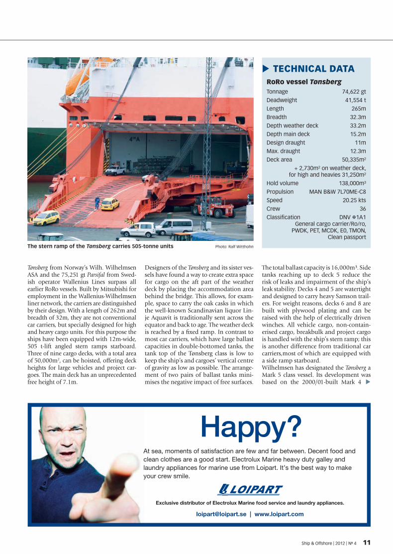
Tønsberg from Norway’s Wilh. Wilhelmsen ASA and the 75,251 gt Parsifal from Swed-ish operator Wallenius Lines surpass all earlier RoRo vessels. Built by Mitsubishi for employment in the Wallenius-Wilhelmsen liner network, the carriers are distinguished by their design. With a length of 262m and breadth of 32m, they are not conventional car carriers, but specially designed for high and heavy cargo units. For this purpose the ships have been equipped with 12m-wide, 505 t-lift angled stern ramps starboard. Three of nine cargo decks, with a total area of 50,000m2, can be hoisted, offering deck heights for large vehicles and project car-goes. The main deck has an unprecedented free height of 7.1m.
Designers of the Tønsberg and its sister ves-sels have found a way to create extra space for cargo on the aft part of the weather deck by placing the accommodation area behind the bridge. This allows, for exam-ple, space to carry the oak casks in which the well-known Scandinavian liquor Lin-je Aquavit is traditionally sent across the equator and back to age. The weather deck is reached by a fi xed ramp. In contrast to most car carriers, which have large ballast capacities in double-bottomed tanks, the tank top of the Tønsberg class is low to keep the ship’s and cargoes’ vertical centre of gravity as low as possible. The arrange-ment of two pairs of ballast tanks mini-mises the negative impact of free surfaces.
The total ballast capacity is 16,000m³. Side tanks reaching up to deck 5 reduce the risk of leaks and impairment of the ship’s leak stability. Decks 4 and 5 are watertight and designed to carry heavy Samson trail-ers. For weight reasons, decks 6 and 8 are built with plywood plating and can be raised with the help of electrically driven winches. All vehicle cargo, non-contain-erised cargo, breakbulk and project cargo is handled with the ship’s stern ramp; this is another difference from traditional car carriers,most of which are equipped with a side ramp starboard. Wilhelmsen has designated the Tønsberg a Mark 5 class vessel. Its development was based on the 2000/01-built Mark 4
RoRo vessel TønsbergTonnage 74,622 gt
Deadweight 41,554 t
Length 265m
Breadth 32.3m
Depth weather deck 33.2m
Depth main deck 15.2m
Design draught 11m
Max. draught 12.3m
Deck area 50,335m²
+ 2,730m² on weather deck, for high and heavies 31,250m²
Hold volume 138,000m³
Propulsion MAN B&W 7L70ME-C8
Speed 20.25 kts
Crew 36
Classifi cation DNV �1A1 General cargo carrier/Ro/ro, PWDK, PET, MCDK, E0, TMON, Clean passport
TECHNICAL DATA �
The stern ramp of the Tønsberg carries 505-tonne units Photo: Ralf Witthohn
�
Ship & Offshore | 2012 | No 4 11
SPI_004-12_10_33_20120514132504_504942.indd 11 14.05.2012 13:25:51
vehicle carriers Tamerlane, Talisman, Tarago and Tamesis, in which fuel reduction per cargo unit is said to have improved by up to 20%. The Malta-fl agged Tønsberg and Singapore-fl agged Parsifal are being employed in Wallenius-Wilhelmsen’s round-the-world service and undertake four-month voyages from Europe to the US East Coast, Oceania, Southeast Asia, Far East, US West and East coasts and back to Europe. They reach speeds of over 20 knots, produced by a cross-head main
engine whose exhaust gases drive a steam turbine generator and thus cut fuel con-sumption by up to 6%.
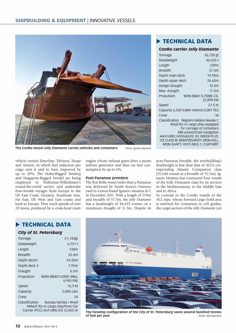
Post-Panamax premiere The fi rst RoRo vessel wider than a Panamax was delivered by South Korea’s Daewoo yard to Genoa-based Ignazio Messina & C in December 2011. With a length of 239m and breadth of 37.5m, the Jolly Diamante has a deadweight of 46,635 tonnes on a maximum draught of 11.5m. Despite its
post-Panamax breadth, the newbuilding’s deadweight is less than that of ACL’s cor-responding Atlantic Companion class (51,648 tonnes at a breadth of 32.2m). Ig-nazio Messina has contracted four vessels of the Jolly Diamante class for its services in the Mediterranean, to the Middle East and to Africa. In contrast to the ConRo vessels of the ACL type, whose forward cargo hold area is reserved for containers in cell guides, the cargo section of the Jolly Diamante can
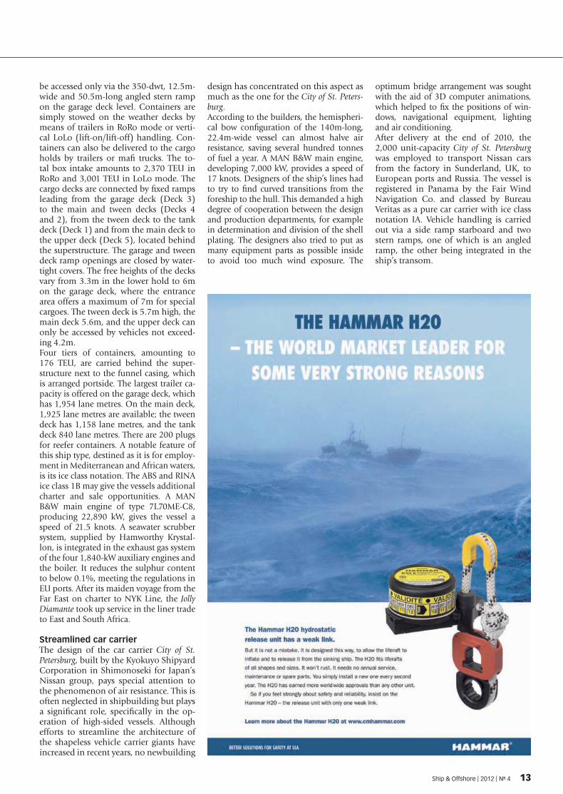
City of St. PetersburgTonnage 21,143gt
Deadweight 4,721 t
Length 140m
Breadth 22.4m
Depth deck9 24.45m
Depth deck 3 7.95m
Draught 6.5m
Propulsion MAN B&W7L42MC Mk6, 6,965 kW,
Speed 16,9 kt
Capacity 2,000 cars
Crew 24
Classifi cation Bureau Veritas I �Hull �Mach Ro-ro cargo ship/Pure Car Carrier (PCC) AUT-UMS ICE CLASS IA
TECHNICAL DATA �
The foreship confi guration of the City of St. Petersburg saves several hundred tonnes of fuel per year Photo: Ralf Witthohn
ConRo carrier Jolly DiamanteTonnage 50,720 gt
Deadweight 46,635 t
Length 239m
Breadth 37.5m
Depth main deck 19.95m
Depth upper deck 26.65m
Design draught 10.5m
Max. draught 11.5m
Propulsion MAN B&W 7L70ME-C8, 22,890 kW
Speed 21.5 kt
Capacity 6,269 trailer metres/3,001 TEU
Crew 36
Classifi cation Registro Italiano Navale C �Hull Ro-ro cargo ship equipped for carriage of containers MN unrestricted navigation��AUT-UMS; FATIGUELIFE 30; GREEN PLUS; ICE CLASS IB; INWATERSURVEY; MON-HULL, MON-SHAFT; �SYS-NEQ-1; COAT-WBT
TECHNICAL DATA �
The ConRo vessel Jolly Diamante carries vehicles and containers Photo: Ignazio Messina
12 Ship & Offshore | 2012 | No 4
SHIPBUILDING & EQUIPMENT | INNOVATIVE VESSELS
SPI_004-12_10_33_20120514132504_504942.indd 12 14.05.2012 13:25:5
be accessed only via the 350-dwt, 12.5m-wide and 50.5m-long angled stern ramp on the garage deck level. Containers are simply stowed on the weather decks by means of trailers in RoRo mode or verti-cal LoLo (lift-on/lift-off) handling. Con-tainers can also be delivered to the cargo holds by trailers or mafi trucks. The to-tal box intake amounts to 2,370 TEU in RoRo and 3,001 TEU in LoLo mode. The cargo decks are connected by fi xed ramps leading from the garage deck (Deck 3) to the main and tween decks (Decks 4 and 2), from the tween deck to the tank deck (Deck 1) and from the main deck to the upper deck (Deck 5), located behind the superstructure. The garage and tween deck ramp openings are closed by water-tight covers. The free heights of the decks vary from 3.3m in the lower hold to 6m on the garage deck, where the entrance area offers a maximum of 7m for special cargoes. The tween deck is 5.7m high, the main deck 5.6m, and the upper deck can only be accessed by vehicles not exceed-ing 4.2m. Four tiers of containers, amounting to 176 TEU, are carried behind the super-structure next to the funnel casing, which is arranged portside. The largest trailer ca-pacity is offered on the garage deck, which has 1,954 lane metres. On the main deck, 1,925 lane metres are available; the tween deck has 1,158 lane metres, and the tank deck 840 lane metres. There are 200 plugs for reefer containers. A notable feature of this ship type, destined as it is for employ-ment in Mediterranean and African waters, is its ice class notation. The ABS and RINA ice class 1B may give the vessels additional charter and sale opportunities. A MAN B&W main engine of type 7L70ME-C8, producing 22,890 kW, gives the vessel a speed of 21.5 knots. A seawater scrubber system, supplied by Hamworthy Krystal-lon, is integrated in the exhaust gas system of the four 1,840-kW auxiliary engines and the boiler. It reduces the sulphur content to below 0.1%, meeting the regulations in EU ports. After its maiden voyage from the Far East on charter to NYK Line, the Jolly Diamante took up service in the liner trade to East and South Africa.
Streamlined car carrierThe design of the car carrier City of St. Petersburg, built by the Kyokuyo Shipyard Corporation in Shimonoseki for Japan’s Nissan group, pays special attention to the phenomenon of air resistance. This is often neglected in shipbuilding but plays a signifi cant role, specifi cally in the op-eration of high-sided vessels. Although efforts to streamline the architecture of the shapeless vehicle carrier giants have increased in recent years, no newbuilding
design has concentrated on this aspect as much as the one for the City of St. Peters-burg.According to the builders, the hemispheri-cal bow confi guration of the 140m-long, 22.4m-wide vessel can almost halve air resistance, saving several hundred tonnes of fuel a year. A MAN B&W main engine, developing 7,000 kW, provides a speed of 17 knots. Designers of the ship’s lines had to try to fi nd curved transitions from the foreship to the hull. This demanded a high degree of cooperation between the design and production departments, for example in determination and division of the shell plating. The designers also tried to put as many equipment parts as possible inside to avoid too much wind exposure. The
optimum bridge arrangement was sought with the aid of 3D computer animations, which helped to fi x the positions of win-dows, navigational equipment, lighting and air conditioning.After delivery at the end of 2010, the 2,000 unit-capacity City of St. Petersburg was employed to transport Nissan cars from the factory in Sunderland, UK, to European ports and Russia. The vessel is registered in Panama by the Fair Wind Navigation Co. and classed by Bureau Veritas as a pure car carrier with ice class notation IA. Vehicle handling is carried out via a side ramp starboard and two stern ramps, one of which is an angled ramp, the other being integrated in the ship’s transom.
Ship & Offshore | 2012 | No 4 13
SPI_004-12_10_33_20120514132504_504942.indd 13 14.05.2012 13:2 :23

SHIPBUILDING & EQUIPMENT | GREEN SHIP TECHNOLOGY
Advanced waste fuel recovery system introducedPUREDRY Alfa Laval has announced it will offi cially launch of an innovative high-speed separa-tor able to recover reusable fuel from waste fuel oil at this year’s SMM in Hamburg. Called PureDry, the unconventionally designed separator has been developed to recover energy by recycling the heavy fuel oil fraction in the waste fuel oil tank, leaving only super-dry solids that can be landed as dry waste.
Alfa Laval sees waste fuel recovery (WFR) as a new, game-changing applica-
tion that will bring the shipping industry huge fuel savings.With high oil prices, bunker fuel oil accounting for about 60% of a vessel’s operating costs, and increasingly stringent emission controls, a fuel strategy and ways to cut fuel bills are at the top of the agenda for most shipowners and operators today. In addition to looking at technical measures to cut fuel bills, such as exhaust gas cleaning and other tech-nologies, shipowners are being compelled to reduce speed, re-move destinations from their itineraries, and so on. However, it is now permissible to re-use waste fuel and, accord-ing to Alfa Laval, for the fi rst time there is a technically and economically effi cient method of recovering waste fuel from fuel oil residues. With waste fuel recovery, a direct saving of up to 2% on fuel bills can be achieved – an investment that pays for itself and gives a healthy profi t in the fi rst year.
Operability of WFRWaste fuel oil comes from set-tling and day tank drainages, leakages, fi lters and purifi ers and is collected today in the waste oil tank and subsequent-ly landed or incinerated. Alfa Laval’s WFR concept in-volves installing two waste oil tanks, one for lube oil (LO) and the other for fuel oil (FO). Some vessels already have this arrange-ment. Although to the observer the waste fuel oil tank appears to contain just black oil, it is actually oil-polluted water con-
taining 20–30% energy in the form of recoverable fuel oil. The remaining 70-80% is oil-pollut-ed water and, accumulating at the bottom, suspended solids making up about 1%.
Reusable FO returned to the bunker tankDescribed by Alfa Laval as the fi rst truly successful technol-ogy for waste oil treatment, the PureDry separator recovers the fuel oil from the oily water in the waste FO tank; it is then returned to the fuel oil bun-ker tank for re-use after normal treatment. For the shipowner, the result is a reduction of up to 2% in the total volume of fuel oil consumed and a correspond-ing reduction in the ship’s fuel bill.The process reduces the volume of waste oil by 99%, producing
typically 5-15 kg per day of non-pumpable “super-dry” solids that can be landed as dry waste and disposed of in the same way as oily rags and used fi lter cartridges. There are no oil loss-es, and no additional wastes are generated. The separated water, now with an oil content of less than 1,000 ppm, is pumped to the bilge water system.
Profit within the first yearPauli Kujala, senior business manager, Oily Waste Treatment Systems, Alfa Laval Marine & Diesel Equipment: “A large con-tainer vessel or cruise ship, sail-ing 52 weeks per year, typically burns 1,000 tonnes of fuel per week. Now, with PureDry recov-ering fuel that would otherwise be treated as waste, it will be pos-sible to cut the ship’s fuel bill by up to 2%, which amounts to at
least USD 500,000 per annum at today’s bunker prices.”
Problems with full waste oil tanks eliminatedPureDry also solves the prob-lem of the waste oil tank fi lling up. The waste oil is treated in-stead of being stored for subse-quent incineration or landing. If the oily water separator (OWS) does not function properly, the bilge water goes into recircula-tion and fi lls up the bilge wa-ter tank. When this is full, it is usually pumped to the waste oil tank. When the waste oil tank has no more capacity, the ship has a problem. Incineration of the waste oil means burning up to 80% water, and to do this it is necessary to add costly die-sel fuel. Alfa Laval’s new waste oil treatment concept is said to solve the problem.
The PureDry and PureBilge integrated system
�
14 Ship & Offshore | 2012 | No 4
SPI_004-12_10_33_20120514132504_504942.indd 14 14.05.2012 13:2 :24

��������������������
SPI_004-12_10_33_20120514132504_504942.indd 15 14.05.2012 13:2 :31

Landing waste oil can be costlyThere are also problems today with landing of waste oils. In many ports, it is diffi cult. For instance, California is not pre-pared to handle waste oil. If landed, it has to be transport-ed by road tanker to a neigh-bouring US state for disposal. This, of course, means the shipowner has to pay dearly for it. In some places it is possible to sell waste oil, probably for about USD 110 per tonne, although the price depends on the water content. But in these cases, shipowners are getting paid for oil they once purchased at full price. In fact, they are selling it at a huge dis-count to someone else, when they could re-use it them-selves.
Flows metered and recordedThe PureDry system has ac-curate fl ow metering in the EPC 60 control unit. The feed is monitored, recovered oil is
metered, the water is metered and a load cell registers when the dry solids container is full. All this is digitally recorded for presentation to the authori-ties during, for instance, port state controls. Fuel has been recycled, but no oily waste is missing from the ORB records because the recovered oil has been metered and logged.
Paradigm shift in separationThe new PureDry generation represents a paradigm shift in high-speed disc stack separator solids discharge design. With PureDry, there is no aperture in the bowl and no sensitive hydraulic system installed to actuate solids discharge.A patented, spiral-shaped de-vice, called the XCavator, trans-ports the super-dry solids to the base of the machine, where they exit down into a container below the machine.There are only two main mov-ing/rotating parts – the separa-tor insert including the XCava-tor, and the outer bowl shell. They move in the same direc-tion but at different speeds, thus transporting the dry solids out of the machine. The essence of the PureDry con-cept and the thinking behind the choice of name is that no water is added. The new design completely eliminates the need for displacement water prior to discharge, as well as water needed for conventional hy-
draulically controlled discharge mechanisms. And, as men-tioned earlier, the solids are dis-charged in super-dry form.
‘Maintenance and Service by Exchange’Alfa Laval has also developed an innovative, module-based maintenance concept called Maintenance and Service by Exchange (MSE). PureDry is supplied with an exchange kit, which includes a new separator insert (rotor and disc stack), a new XCavator, and a consuma-bles kit. After one year, the crew replaces the separator insert as simply as replacing the insert in a fi lter, along with the XCava-tor. The used parts are returned to the nearest Alfa Laval Service Centre, and the ship orders a new exchange (and consuma-bles) kit. “The customer is not purchasing new parts – we supply the kit at an exchange price,” says Pauli Kujala. “And the PureDry separator remains under continuous warranty. This is virtually all that needs to
Alfa Laval’s new waste fuel recovery unit
������������ ������������
LifeboatDavits
ControlablePitch PropellerCPP
SteeringGear
Thrusters
Cranes
SharkJaws
SternTubes
Winches
Gears Lube Oil MDO/MGOFuel
HydraulicPower Packs
Bow Thrusters
Hydraulic Valves
�����������������������
Water ingress in thrusters
Gearbox failures
������������cranes
Dirty fuel
Clean Oil - Bright IdeasC.C.JENSEN A/S | www.cjc.dk
���� �!���� ��"�����������������
Meet us at:
#��������June 4 - 8, 2012 Athens, Greece
16 Ship & Offshore | 2012 | No 4
SHIPBUILDING & EQUIPMENT | GREEN SHIP TECHNOLOGY
SPI_004-12_10_33_20120514132504_504942.indd 1 14.05.2012 13:2 :31

be done to keep the equipment in good operating order. The aim is to give customers the op-portunity to budget and main-tain a fi xed operating cost.”For full operational security, PureDry is equipped with an advanced integrated condition-based monitoring (CBM) sys-tem that records temperature and vibration via the EPC 60 control unit. The system can give the crew an early alert or even shut down the machine if the running conditions should suddenly deviate from speci-fi cations. Action can then be taken based on recommenda-tions from the CBM system – it may be a recommendation to run the cleaning-in-place (CIP) process or exchange a compo-nent using the exchange kit.
Integrated waste oil and bilge water systemTogether, PureDry and Alfa Laval’s PureBilge bilge water separator form an integrated waste oil and bilge water han-dling system. It recovers waste
FO that is returned to the fuel oil bunker tank, treats waste LO to reduce the volume, cleans the bilge water to 0-5 ppm for discharge overboard, and gener-ates small volumes of super-dry solids for landing as dry waste. PureBilge is the fi rst system of its type to pass the new, more stringent DNV 5 ppm type approval process for oily wa-ter separators. It provides a cleaning performance in real-life conditions of 0-5 ppm oil content in the water without chemicals, adsorption fi lter or membranes. PureBilge is delivered with the integrated tamper-proof BlueBox bilge data recording system.
Environmental benefits If the world’s merchant fl eet cut its fuel bill by 2%, there would be a reduction in HFO consumption of approximately 10.4 million tonnes per year and the amount of CO2 re-leased annually would be re-duced by 32 million tonnes, according to Alfa Laval.
Sewage treatment MARINER OMNIPURE® | Severn Trent De Nora, provider of water disinfection units, in-troduced the next generation of its marine sewage treatment system, Mariner Omnipure®, at this year’s Asia Pacifi c Mari-time exhibition in Singapore. The units of the series M55 are more compact and lightweight, making them well-suited for workboats and smaller marine vessels, the manufacturer said. It uses the company’s propri-etary electrolytic disinfection
technology and offers a unique approach to wastewater treat-ment for smaller vessel, work-boat and yacht applications. It has a bulkhead-mounted ar-rangement – a fi rst of its kind – that provides safe and effective treatment of black- and grey-water, resulting in wastewater effl uent quality that meets the requirements of the Interna-tional Maritime Organization’s (IMO) MEPC.159(55), accord-ing to Severn Trent De Nora. The Mariner Omnipure system has been developed to treat sewage from marine applica-tions and help lessen the envi-ronmental impact of contami-nants. The electrolytic process generates a powerful oxidant from sea water to effectively disinfect biological wastes. The series M55 systems can accom-modate treatment capacities up to 75 persons for black water and up to 25 persons for black- and greywater.
The new generation of the ma-rine sewage treatment system
Industry
RIGHT ON COURSE EXPERTISE ON BOARD
Our innovative filtration and separation systems are on board
throughout the world.
� Bilge water de-oiling� Ballast water treatment� Sea water desalination� Fuel treatment and filtration for MDO and HFO� Lubricating oil treatment and filtration� Hydraulic filter systems
As a development and system partner, we make a significant
contribution in the shipping industry to improving safety and
efficiency, as well as controlling water pollution worldwide.
Filtration and separation for shipping and industry.
www.mahle-industrialfiltration.com
SPI_004-12_10_33_20120514132504_504942.indd 1 14.05.2012 13:2 :3
SHIPBUILDING & EQUIPMENT | PROPULSION & MANOEUVRING TECHNOLOGY
S.A. AGULHAS II The design of the Antarctic research and supply vessel S.A. Agulhas II is based on a differentiated operating profi le. Shipbuilding expert Ralf Witthohn describes how the occupational prognosis by the South African Ministry of Transport infl uenced GE Energy Power Conversion’s design of the electrical components of the ship’s propulsion and automa-tion system.
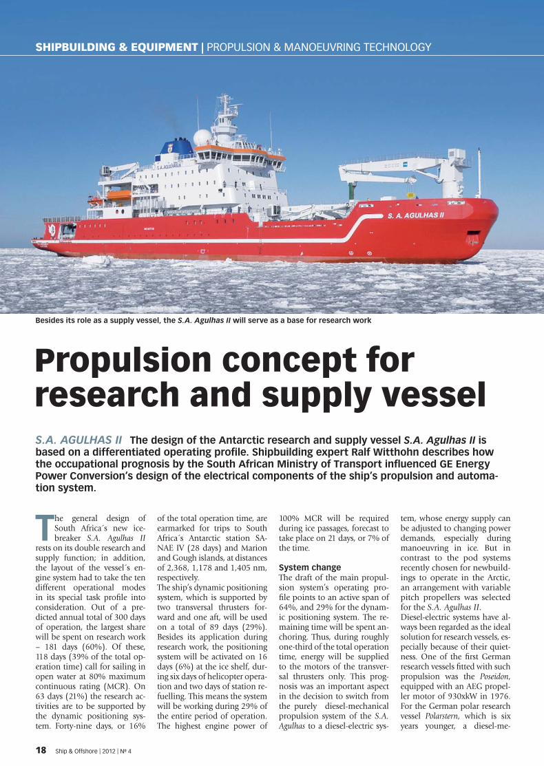
The general design of South Africa´s new ice-breaker S.A. Agulhas II
rests on its double research and supply function; in addition, the layout of the vessel´s en-gine system had to take the ten different operational modes in its special task profi le into consideration. Out of a pre-dicted annual total of 300 days of operation, the largest share will be spent on research work – 181 days (60%). Of these, 118 days (39% of the total op-eration time) call for sailing in open water at 80% maximum continuous rating (MCR). On 63 days (21%) the research ac-tivities are to be supported by the dynamic positioning sys-tem. Forty-nine days, or 16%
of the total operation time, are earmarked for trips to South Africa´s Antarctic station SA-NAE IV (28 days) and Marion and Gough islands, at distances of 2,368, 1,178 and 1,405 nm, respectively.The ship’s dynamic positioning system, which is supported by two transversal thrusters for-ward and one aft, will be used on a total of 89 days (29%). Besides its application during research work, the positioning system will be activated on 16 days (6%) at the ice shelf, dur-ing six days of helicopter opera-tion and two days of station re-fuelling. This means the system will be working during 29% of the entire period of operation. The highest engine power of
100% MCR will be required during ice passages, forecast to take place on 21 days, or 7% of the time.
System changeThe draft of the main propul-sion system’s operating pro-fi le points to an active span of 64%, and 29% for the dynam-ic positioning system. The re-maining time will be spent an-choring. Thus, during roughly one-third of the total operation time, energy will be supplied to the motors of the transver-sal thrusters only. This prog-nosis was an important aspect in the decision to switch from the purely diesel-mechanical propulsion system of the S.A. Agulhas to a diesel-electric sys-
tem, whose energy supply can be adjusted to changing power demands, especially during manoeuvring in ice. But in contrast to the pod systems recently chosen for newbuild-ings to operate in the Arctic, an arrangement with variable pitch propellers was selected for the S.A. Agulhas II. Diesel-electric systems have al-ways been regarded as the ideal solution for research vessels, es-pecially because of their quiet-ness. One of the fi rst German research vessels fi tted with such propulsion was the Poseidon, equipped with an AEG propel-ler motor of 930xkW in 1976. For the German polar research vessel Polarstern, which is six years younger, a diesel-me-
Propulsion concept for research and supply vessel
Besides its role as a supply vessel, the S.A. Agulhas II will serve as a base for research work
18 Ship & Offshore | 2012 | No 4
SPI_004-12_10_33_20120514132504_504942.indd 1 14.05.2012 13:2 :40
chanical system was chosen to secure its operational readiness during long supply voyages to the Antarctic and journeys into both polar zones. The fi rst ver-sion of the European icebreak-er design Aurora Borealis, com-pleted in 2008, was fi tted with three conventional propulsion propellers and six transversal thrusters based on a diesel-electric system able to supply 81,000 kW to the three main propellers. At the end of 2011, a smaller version of the Aurora Borealis with three 15,000 kW pod drives was tested as a model in a Finnish ice tank. A diesel-electric system will also drive the replacement of the German deep-sea research ves-sel Sonne, to be delivered to the German government by Nep-tun Werft in Rostock, Germany, in 2013.
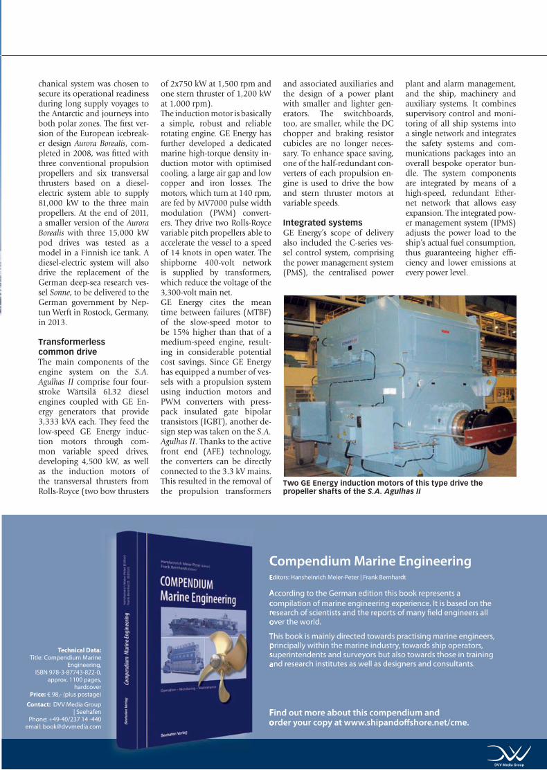
Transformerless common drive The main components of the engine system on the S.A. Agulhas II comprise four four-stroke Wärtsilä 6L32 diesel engines coupled with GE En-ergy generators that provide 3,333 kVA each. They feed the low-speed GE Energy induc-tion motors through com-mon variable speed drives, developing 4,500 kW, as well as the induction motors of the transversal thrusters from Rolls-Royce (two bow thrusters
of 2x750 kW at 1,500 rpm and one stern thruster of 1,200 kW at 1,000 rpm). The induction motor is basi cally a simple, robust and reliable rotating engine. GE Energy has further developed a dedicated marine high-torque density in-duction motor with optimised cooling, a large air gap and low copper and iron losses. The motors, which turn at 140 rpm, are fed by MV7000 pulse width modulation (PWM) convert-ers. They drive two Rolls-Royce variable pitch propellers able to accelerate the vessel to a speed of 14 knots in open water. The shipborne 400-volt network is supplied by transformers, which reduce the voltage of the 3,300-volt main net.GE Energy cites the mean time between failures (MTBF) of the slow-speed motor to be 15% higher than that of a medium-speed engine, result-ing in considerable potential cost savings. Since GE Energy has equipped a number of ves-sels with a propulsion system using induction motors and PWM converters with press-pack insulated gate bipolar transistors (IGBT), another de-sign step was taken on the S.A. Agulhas II. Thanks to the active front end (AFE) technology, the converters can be directly connected to the 3.3 kV mains. This resulted in the removal of the propulsion transformers
and associated auxiliaries and the design of a power plant with smaller and lighter gen-erators. The switchboards, too, are smaller, while the DC chopper and braking resistor cubicles are no longer neces-sary. To enhance space saving, one of the half-redundant con-verters of each propulsion en-gine is used to drive the bow and stern thruster motors at variable speeds.
Integrated systemsGE Energy’s scope of delivery also included the C-series ves-sel control system, comprising the power management system (PMS), the centralised power
plant and alarm management, and the ship, machinery and auxiliary systems. It combines supervisory control and moni-toring of all ship systems into a single network and integrates the safety systems and com-munications packages into an overall bespoke operator bun-dle. The system components are integrated by means of a high-speed, redundant Ether-net network that allows easy expansion. The integrated pow-er management system (IPMS) adjusts the power load to the ship’s actual fuel consumption, thus guaranteeing higher effi -ciency and lower emissions at every power level.
Two GE Energy induction motors of this type drive the propeller shafts of the S.A. Agulhas II
Compendium Marine EngineeringEditors: Hansheinrich Meier-Peter | Frank Bernhardt
According to the German edition this book represents a compilation of marine engineering experience. It is based on the research of scientists and the reports of many fi eld engineers all over the world.
This book is mainly directed towards practising marine engineers, principally within the marine industry, towards ship operators, superintendents and surveyors but also towards those in training and research institutes as well as designers and consultants.
Technical Data:
Title: Compendium Marine Engineering,
ISBN 978-3-87743-822-0, approx. 1100 pages,
hardcover Price: € 98,- (plus postage)
Contact: DVV Media Group | Seehafen
Phone: +49-40/237 14 -440email: [email protected]
Find out more about this compendium and order your copy at www.shipandoff shore.net/cme.
DVV Media Group
SPI_004-12_10_33_20120514132504_504942.indd 19 14.05.2012 13:2 :41
Hydrodynamic effects BIOFILMS Structural roughness of a vessel’s hull may be caused either by the type of con-struction, service condition, poor application of anticorrosive and antifouling paints or micro- and macrofouling. In this article, the fi rst of two parts, Bernd Daehne and Burkard Watermann from LimnoMar, the Laboratory for Aquatic Research, Hamburg, and Ulf Barkmann and Reinhard Schulze from the Ship Model Basin, Potsdam, give a comprehensive overview of the latest studies and fi ndings on the relationship between biofouling and ship resistance.
Hydrophobic surfaces are used as biocide-free coat-ings for the prevention or
reduction of fouling. Their mode of action is not based on the killing of settling stages of foul-ing organisms but is achieved by the reduction of adhesion, thus they are called foul-release or non-stick systems.The range of applications com-prises the hull and propeller of vessels, open cooling systems and aquaculture devices. Paint manufacturers claim a reduc-tion of friction directly after application and fuel savings of up to 6%. Despite these coat-ings’ mechanical fragility, in-terest in them has increased because they contain and leach no biocides. They can be used in sensitive marine areas by cruisers plying shallow waters with intact underwater marine communities. On the other hand, recommendations to reduce CO2 emissions by ship-
ping have focused on foul-free coating with low friction and incorporation into the Energy Effi ciency Design Index (EEDI) for newbuildings (IMO-MEPC, 2008; IMO-GHG, 2009). The smoothness of the hull in the building process (smooth-ing of the welded joints), appli-cation quality of anticorrosive coatings and the antifouling system are of crucial importance (Grigson, 1992). Hydrophobic silicone coatings in particular deserve a high-quality applica-tion. Most paint manufacturers recommend removal of existing anticorrosive and antifouling coatings as a prerequisite for the application of silicone coat-ings. Otherwise, the claimed re-duction in friction may not be achieved (Daehne et al., 2001; Watermann et al., 2000, 2003). Biofi lm formation was as-sumed to smooth welded joints and failures due to poor application. In contrast, Loeb
(1984) reported on increased friction on surfaces covered by biofi lms. Similar observa-tions were made on biocidal antifouling systems primarily based on copper and organotin that were free of macrofouling but sometimes densely cov-ered with biofi lms (Loeb et al., 1984; Jelic-Mrcelic et al., 2006). Consequently, foul-re-lease systems were designed to lower the adhesion of macro- and microfouling organisms to such a degree that they can be permanently cleaned of both types of fouling at serv-ice speed. Nevertheless, satis-factory performance of these coatings can only be achieved at a service speed of more than 20 knots and at activity levels of more than 80%. At a lower service speed and activity levels below 80%, biofi lm formation can be observed (op cit). Attempts to measure the contri-bution of biofi lms to the friction
of the hull are hampered by the fact that their composition can be very heterogenous, varying in species, in height and length of the organisms, in surface struc-ture and in topography. Bio-fi lms are predominantly com-posed of viruses, bacteria, fungi and unicellular algae – like dia-toms. Multicellular, fi lamentous algae occur on ship hulls and can contribute additional drag of 110-125% (Schultz, 2000). Furthermore, biofi lms incor-porate small particles like sand grains and suspended matter, which severely infl uence their consistency and surface topog-raphy. As bacteria in biofi lms produce extracellular polymer substances (EPS), some authors suggested a reduction in friction by continuous shedding of the surface layers of EPS (Schultz and Swain, 2000). These ex-pectations were nourished by laboratory experiments in pipes with added polymers like PEG, which reduced the friction at suffi cient concentrations near the pipe wall (Harder and Tied-ermann, 1991).
Measurement of surface roughness The sharp increase in fuel costs in the 1970s prompted several investigations on the effect of fouling and hull roughness on fuel consumption, speed and performance. It was estimated that the fl eet of the Royal Navy burned 20% more fuel because of fouling and consequent hull roughness. This led to forma-tion of the Ship Performance Group. Townsin and his co-workers focused on the rela-tionship between propulsion, speed and hull roughness. They introduced the term “mean
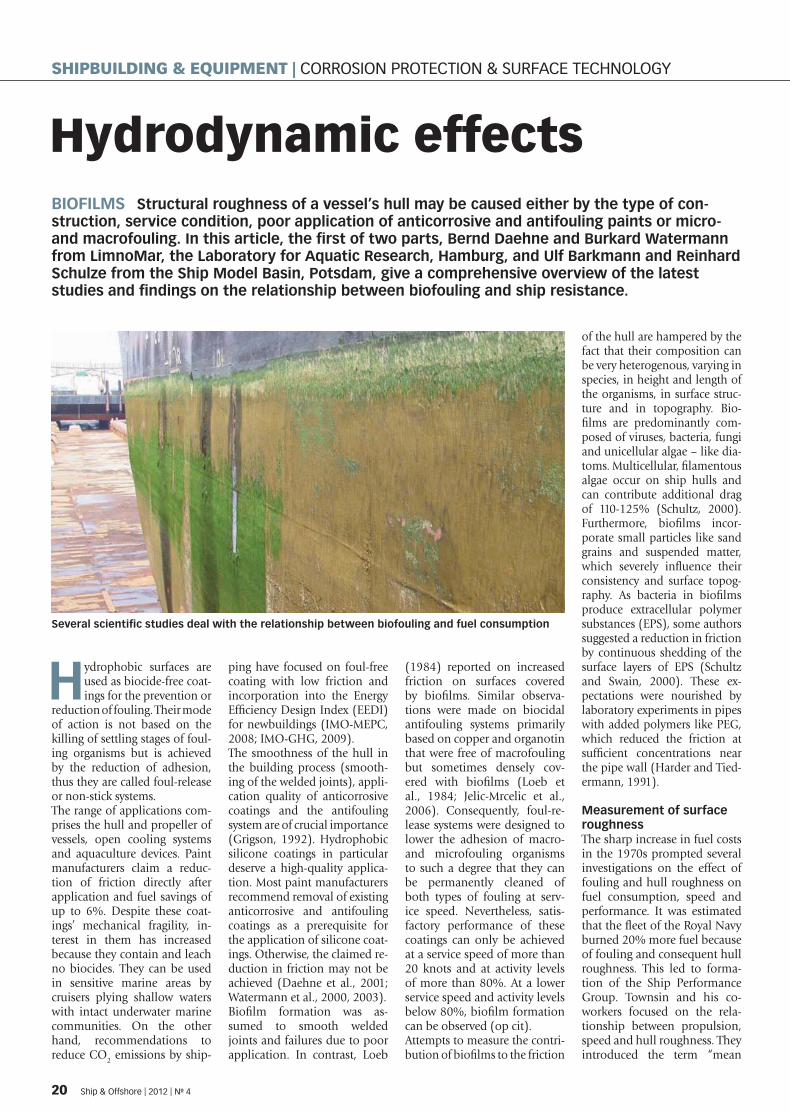
Several scientifi c studies deal with the relationship between biofouling and fuel consumption
20 Ship & Offshore | 2012 | No 4
SHIPBUILDING & EQUIPMENT | CORROSION PROTECTION & SURFACE TECHNOLOGY
SPI_004-12_10_33_20120514132504_504942.indd 20 14.05.2012 13:2 :43

hull roughness” (MHR), gained by measurements at more than 100 positions evenly spread over the hull wetted surface from a dozen 50mm-sampling lengths. The average of the MHR values is the average hull roughness (AHR).Townsin gave examples of measured hull roughness val-ues at various ages and condi-tions (Tab. 1).Measurements of hull rough-ness of ships in service revealed an increase of 2-4 μm/month given an antifouling system of low quality and mechanical damage, whereas a decrease was noted on ships with self-polishing antifouling systems (at that time TBT-based SPCs) of 3 μm/month.The results of the Ship Perform-ance Group initiated a broad discussion of quality improve-ment during the building phase and of paint application tech-niques (Townsin et al., 1980). In addition, the group proposed a separation of hull and propeller roughness due to their different contributions to ship perform-ance (Townsin et al., 1981). In the 1980s, several publications dealt with the theoretical basics of the fl ow regime on surfaces and appropriate methods for their determination (Musker 1981; Ligrani, 1982; Granville, 1987). More recently, Howell and Behrends (2006) pub-lished a comprehensive review of methods for measuring hull roughness and the measurabil-ity of surface roughness. The authors presented some basic assumptions as prerequisites: Viscous drag occurs in the layer of fl uid in the immediate vi-cinity of a bounding surface, known as a boundary layer. At high Reynolds numbers (the ratio of inertial forces to vis-cous forces), it is desirable to have a laminar boundary layer as this imparts less friction to the bounding surfaces and is a prerequisite for the effi cacy and leaching process of biocidal antifouling paints. As a fl uid fl ows along a surface, it inevita-bly becomes turbulent, impart-ing more drag, although the laminar sublayer remains in the range of 10–50 μm adjacent to the surface. On ship hulls, small
projections due to the building process, paint application and structure play an important role depending on their height. If the height of the projections is small in relation to the bound-ary sublayer, then the surface will remain smooth. At increas-ing Reynolds numbers, and a decrease in the thickness of the boundary layer, the rough-ness and the drag will increase. Nikuradse developed a concept for this transient condition, called the critical roughness height concept, which states that there is a critical roughness height below which there is no increase in drag: the “hydrody-namically smooth condition”. The hull of ships may have four types of roughness:
Structural roughness caused �by the type of construction (weld spots),Structural roughness caused �by service conditions (me-chanical damage, tug im-pact, berthing),Roughness caused by poor �application of anticorrosive and antifouling paints (sag-ging, orange peel, cratering, blistering, etc.),Micro- and macrofouling. �
To estimate the contribution of biofi lms/microfouling, the mi-cro-roughness is of crucial im-portance. The surface structure of an antifouling or anticorro-sive coating contributes with its properties like waviness, direc-tion of the surface texture, and failure. Especially the last of these favours the attachment of settling stages of fouling organ-isms including bacteria, thus increasing the roughness.It is evident that modelling the increase in roughness with computational fl uid dynam-ics programs is impossible on a unifactorial basis. Ow-
ing to these diffi culties, the values given in the literature are very heterogeneous. For a long time, it was assumed that an increase in roughness of 10 μm would lead to an increase in frictional resistance of 1% (Lackenby, 1962). Contrary to this assumption, Weinell et al. (2003) recorded an increase in frictional resistance of 4% at an increase of 5% in roughness in laboratory experiments.
Influence of microbial biofilms on hydrodynamic dragLewthwaite et al. (1984) con-ducted comprehensive trials and investigations on the con-tribution of biofi lms to the in-crease of frictional resistance on ship hulls. They published monitoring data gained on ships in service, which were scarce at that time in contrast to theoretical calculations. Sev-eral theoretical premises were included in the design of meas-urements: the law of the wall theory, boundary layer profi les of the free stream velocity and the sublayer cut-off, viscosity of the sea water depending on salinity and temperature. The vessel used for the trials was a 23m-long fl eet tender operat-ing around Portsmouth Har-bour. At the start of the trials, the vessel had just completed a refi t during which the hull was cleaned, shot-blasted and repainted with an anticorrosive coating and an eroding biocidal antifouling paint. Along with fouling sampling plates, a sea tube giving access for the probe equipment was welded into the hull 10.3m from the bow and 0.6m from the centreline of the keel. Twenty-nine sea tri-als started after four days afl oat from September 1979 to No-
vember 1981, covering 771 days in service. The condition of the hull was regularly surveyed by divers, who reported the foul-ing development and at inter-vals removed the fouling plates for the evaluation of fouling de-gree and composition. The sur-veys revealed that a biofi lm de-veloped rapidly on the hull and steadily increased in thickness up to 1000 μm, which was hard to measure due to its softness. The biofi lm was composed of bacteria and diatoms present in summer and autumn. After one year, brown algae and singular barnacles were observed. An initial roughness survey after the application of the antifouling paint resulted in a mean value of 198 μm and an average of 207 μm upstream of the probe position, indicat-ing that the probe position was representative of the general roughness state. An overall in-crease in Cf of about 25% after 240 days, and 80% after 771 days afl oat, was determined.Because of the increase in fuel consumption due to biofi lm formation, the US Navy con-ducted laboratory and fi eld-based investigations on the biofi lm effect on drag. As the docking interval for US Navy ships varied from four to six years, underwater cleaning was ordered when the macrofoul-ing covered 10% of the hull. For laboratory experiments, 24 antifouling paints were applied on rotating disks. The disks were evaluated in three conditions:
freshly painted, �after four to fi ve months of �exposure in brackish water,after removal of the slime �layer with a rubber squeegee.
Torque measurements were con-ducted using a friction disk ma-chine. Comparison of the labo-ratory results with those of the ship trials was done using the treatment of Granville (1978), allowing the interconversion of drag estimates among spinning disk fl ow and fl at plate fl ow. In addition, a full-scale trial was performed on a frigate, home-ported in Pearl Harbour and freshly painted with an ablative antifouling system based on cuprous oxide and tributyltin oxide as the main biocides.
Ship condition AHR (μm)
New ship during construction, plate wheel-abraded and primed
40 – 60
New ship coated with anticorrosive and antifouling paint
80 – 180
Ship after three years in service 110 – 350Ship after six years in service 130 – 650Ship after 14 years in service 380 – 1100
�Table 1: Hull roughness at various ages and conditions
Ship & Offshore | 2012 | No 4 21
SPI_004-12_10_33_20120514132504_504942.indd 21 14.05.2012 13:2 :45

To determine the effect of bio-fi lms on ship performance, an Accurex shaft torsion meter was installed. The hull was sur-veyed prior to trials by divers and the hull roughness was determined. Microfouling was removed by underwater hull cleaning using soft brushes. The presence of microbial bio-fi lms on the rotating disks was shown to increase drag signifi -cantly. The best three coatings showed only a 0-9% increase in drag, whereas one coating showed an increase of 21–30%. Most coatings performed with an increase of 10–19% at 25 knots. The biofi lm thickness, ranging from 1,200–2,700 μm, did not correlate with the increase in drag. The ship trial revealed that 8–18% less power was required to achieve a speed of 25 knots after removal of the microbial fi lm by cleaning.Candries et al. (2003) studied the frictional resistance of hy-drophobic foul-release coat-ings, comparing them with copper-based self-polishing coatings. Preliminary studies on silicones revealed a reduc-tion in friction of 2–20%. The difference was thought to be due to the elastic modulus and the smooth surface of the silicone. Rotor measurements were carried out using differ-ent cylinders coated with both paint types. A correlation be-tween drag and roughness characteristics clearly showed the infl uence of the surface tex-ture, which cannot suffi ciently be determined in one dimen-sion. The foul-release coating had a wavy texture, whereas the copper SPC displayed a surface with a narrow spiky texture. In addition, the mode of ap-plication played a signifi cant
role in the resulting surface topography. Application of the foul-release coating resulted in signifi cantly higher values for the amplitude parameters compared with the application by spraying.Due to the “waviness” instead of “spikiness”, foul-release coatings show a lower mean roughness. Leer-Andersen and Larsson (2003) conducted an experimental-numerical ap-proach to evaluate the skin friction on ships. They out-lined that the relationship between the geometry of a sur-face and its hydrodynamic fric-tion was fairly unknown. The fundamental diffi culty in this respect is that a non-smooth surface cannot be described solely by a single parameter as the average roughness height. Several other parameters are involved, such as arrange-ment, shape, micro-surface and density of rough elements. The common method based on the equivalent sand rough-ness of Schlichting may reveal non-comparable and non-re-alistic results (Schultz and My-ers, 2003). Leer-Andersen and Larsson conducted several ex-periments in pipes and trans-formed the results to full-scale Cf by SHIPFLOW calculations (boundary layer method, one of the three modules of the computational fl uid dynamics code). Measurements were performed in PVC pipes fouled by barna-cles of different densities and heights, and pipes coated with an antifouling system called fi -bre fl ock. The fi bre length was 1mm, and the orientation of fi bres varied between upright or tilted in the direction of fl ow. The results showed that
the performance of the best fi bre fl ock system was com-parable to a surface fouled by barnacles at low density and a roughness height of 0.7mm. In contrast to these fi ndings, they discovered that surfaces fouled by bryozoa decreased the fric-tion, but they did not quantify this effect. Pre-competition treatment of racing sailboats’ slightly rough hulls has been practised for decades. Sanding with 600-grit paper is said to reduce the friction. In another study, Schultz (2004) compared the hydro-dynamic properties of hydro-phobic foul-release coatings with an ablative copper-based antifouling paint and a trib-utyltin-based SPC applied on test plates. The plates were stat-ically exposed for 287 days and their hydrodynamic perform-ance was tested in the 115m-long towing tank of the US Naval Academy in Annapolis at speeds ranging from 2–3.8m/s, corresponding to 5–7 knots. At the lowest Reynolds number, the antifouling coatings tested showed an increase of 1% (sili-cones) and 4% (TBT-SPC) in Cf compared with the smooth control. The 60-grit and 220-grit sandpaper controls ex-hibited increases in Cf of 66% and 17%, respectively. At the highest Reynolds number, the increase in Cf ranged from 4% for the silicones to 1–8% for the TBT-SPC, whereas the 60-grit and 220-grit paper showed increases of 83% and 31%, re-spectively. Measurements of surface roughness revealed softer am-plitudes for the silicone surface compared with the SPCs. The ablative copper and SPC copper antifouling paint showed light
barnacle fouling with fouling degrees of 1–4%, resulting in an increase in Cf of 87–138%. The TBT-SPC showed an in-crease in Cf of 58–68% despite being covered with only a thin biofi lm. The results of the fric-tional resistance tests for the surfaces in a cleaned condi-tion revealed an increased Cf of 3% for the ablative copper antifouling and one silicone formulation, and of 7% for the TBT-SPC compared with the smooth control at the lowest Reynolds number. The increase in Cf for the foul-release coat-ings ranged from 5% for sili-cone one and 15% for silicone two compared with the smooth control at the highest Reynolds number. The extrapolation of the in-crease of frictional resistance of test plates to ship dimensions revealed an increase in Cf of 3% for the silicone one and 6% for the TBT-SPC. The respective values for the fouled condi-tion ranged from 50% for the TBT-SPC and 217% for the sili-cone two. The towing speed of 12 knots was not suffi cient to induce the self-cleaning mech-anism of the silicone to remove the macrofouling.Another comprehensive and detailed study on the relation-ship of biofouling on ship resistance was published by Schultz in 2007, in which the author made predictions of full-scale ship resistance and powering for antifouling coat-ing systems with a range of roughness and fouling condi-tions. His estimates are based on results from laboratory-scale drag measurements and boundary-layer similarity law analysis. His study is the fi rst presenting data of the increase
Description of condition
ΔRt15 knots
Ut = 7.7 m/sec (kN)
ΔRt30 knots
Ut = 15.4 m/sec (kN)
%ΔRt15 knots
Ut = 7.7 m/sec (kN)
%ΔRt30 knots
Ut = 15.4 m/sec (kN)
Hydraulically smooth surface – – – –
After application of AF 4.6 46 2 4
Light slime 23 118 11 10
Heavy slime 41 192 20 16
Small calcareous fouling or weed 69 305 34 25
Medium calcareous fouling 105 447 52 36
Heavy calcareous fouling 162 677 80 55
Table 2: Ship resistance and fouling (Schultz, 2007)
22 Ship & Offshore | 2012 | No 4
SHIPBUILDING & EQUIPMENT | CORROSION PROTECTION & SURFACE TECHNOLOGY
SPI_004-12_10_33_20120514132504_504942.indd 22 14.05.2012 13:2 :45

in resistance related to fouling corroborated by full-scale ship power trials. He presented data in relation to a variety of foul-ing conditions, from biofi lm formation to heavy calcareous fouling. Even the formation of light and heavy biofi lms can in-crease the resistance up to 20% (Tab. 2).Last year, Schultz et al. (2011) published a study on the eco-nomic impact of biofouling and concluded that increased fuel costs due to fouling for-mation are much higher than those related to hull cleaning and painting. A comparable study was published by Munk and Kane (2011) based on their own data collected with the CASPER system on tank-ers, concluding that hull man-agement costs are much lower than additional fuel costs caused by fouling.
A summary of this article was published in Ship&Offshore’s GreenTech Special Edition in 2011.
ReferencesCandries, M., Atlar, M., Mesbahi, E., Pazouk, P. (2003): “The measurement of the drag characteristics of tin-free self-polishing co-polymers and fouling release coatings usin g a rotor apparatus”. Biofouling, 19, 27-36.
Daehne, B., B. Watermann, M. Wiegemann, H. Michaelis, S. Sievers, R. Dannenberg, M. Lindeskog and O. Heemken (2002): “Perfor-mance of biocide-free antifouling paints – Trials on deep-sea going vessels”. Vol. II: Inspections and new applications of 2001 and ecotoxicological aspects.
WWF, Frankfurt, 88 S. + 51 S. Appendix.
Granville, P.S. (1978): “The frictional resi-stance and turbulent boundary layer of rough surfaces”. J. Ship Res. 12, 52–74.
Granville, P.S. (1987): “Three indirect me-thods for the drag characterization of arbi-trarily rough surfaces on flat plates”. J. Ship Res. 31, 1, 70–77.
Grigson, C. (1992): “Drag losses of new ships caused by hull finish”. J. ship Res. 36, 2, 182–196.
Harder, K.J., and Tiedermann, W.G. (1991): “Drag reduction and turbulent structure in two-dimensional channel flows”. Philos. Trans. R. Soc. 336, 19–34.
IMO (2008) “Prevention of air pollution from ships”. MEPC, 58/INF.7, 14S.
IMO (2009) “Consideration of the energy ef-ficiency design index for new ships”. Inter-sessional Meeting of Greenhouse Gas Wor-king Group, GHG-WG 2/2/22, 6S+Annexes
Jelic-Mrcelic, G., Sliskovic, M., Antolic, B. (2006): “Biofouling communities on test pa-nels coated with TBT and TBT-free copper based antifouling paints”. Biofouling, 22, 5/6, 293–302.
Lackenby, H. (1962): “Resistance of ships, with special reference to skin friction and hull surface condition”. Proc. Inst. Mech. Engin. 176, 981–1014.
Leer-Andersen, M., Larsson, L. (2003): “An experimental/numerical approach for evalu-ating skin friction on full-scale ships with sur-face roughness”. Mar. Sci. Technol. 8, 26–36.
Lewthwaite, J.C., Molland, A.F., Thomas, K.W. (1984): “An investigation into the vari-ation of ship skin frictional resistance with fouling”. RINA, 269–284.
Ligrani, P.M. (1989): “Structure of turbulent boundary layers”. In: Chereminosoff, N.P. (ed.). Encyclopedia of Fluid Mechanics, Gulf Publishing, 110–189.
Loeb, G.I., Laster, D., Gracik, T. (1984): “The influence of microbial fouling films on hy-drodynamic drag of rotating discs”. In: Co-stlow, J.D. and Tipper, R. (eds.): Marine Bi-odeterioration. An interdisciplinary study. Naval Inst. Press, Annapolis, 88–94.
Munk, T., Kane, D. (2011): “Technical fuel conservation policy and hull and propeller performance”. RINA, Design and Operation of Tankers Conference, June 2011, 7 pp.
Musker, AJ (1981) Universal roughness functions for naturally occurring surfaces. CSME, 6,1, 1-6.
Schultz, M.P. (2000:) “Turbulent boundary layers on surfaces covered with filamen-tous algae”. J. Fluid Engin. 122, 357–363.
Schultz, M.P. (2002): “The relationship be-tween frictional resistance and roughness for surfaces smoothed by sanding”. Trans. ASME, 124, 492–499.
Schultz, M.P. (2004): “Frictional resistance of an-tifouling systems”. J Fluid Engin. 126, 1039–147.
Schultz, M.P. (2007): “Effects of coating roughness and biofouling on ship resi-stance and powering”. Biofouling, 23(5), 331–341.
Schultz, M.P., Bendick, J.A., Holm, E.R., Her-tel, W.M. (2011): “Economic impact of bio-fouling on a naval surface ship”. Biofouling, 27(1), 87–98.
Schultz, M.P., Swain, G.W. (2000): “The in-fluence of biofilms on skin friction drag”. Biofouling, 15(1-3), 129–139.
Schultz, M.P., Myers, A. (2003): “Compari-son of three roughness function determi-nation methods”. Exp. Fluids, 35, 372–379.
Townsin, R.L., Byrne, D., Milne, A., Svensen, T. (1980): “Speed, power and roughness: The economics of outer bottom mainte-nance”. RINA, 123, 459–475.
Townsin, R.L., Byrne, D., Svensen, T., Milne, A. (1981): “Estimating the technical and economic penalties of hull and propeller roughness”. SNAME Trans. 89, 295–318.
Townsin, R.L., Dey, S.K. (1990): “The corre-lation of roughness drag with surface char-acteristics”. London. RINA, March 1990, 14p.
Watermann, B., B. Daehne, H. Michaelis, S. Sievers, R. Dannenberg and M. Wiegemann (2001): “Performance of biocide-free an-tifouling paints - Trials on deep-sea going vessels”. Vol. I: Application of test paints and inspections of 2000.
WWF, Frankfurt, p.101. + p.106 Appendix.
Watermann, B., B. Daehne, M.Wiegemann, M. Lindeskog and S. Sievers (2003): “Per-formance of biocide-free antifouling paints – Trials on deep-sea going vessels”. Vol III: Inspections and new applications of 2002 and 2003 and synoptical evaluation of re-sults (1998 - 2003). LimnoMar, Hamburg / Norderney, p. 125
Weinell, C.E., Olsen, K.N., Christoffersen, M.W., Kiil, S. (2003): “Experimental study of drag resistance using a laboratory scale ro-tary set-up”. Biofouling 19 (Suppl.) 45– 51.
In an uncertain economic environment, invest in proven performance
COATINGS TESTED BY REALITY SINCE 1915With nearly a century’s marine paint and coating experience, Hempel can always provide the protection you need to
keep business moving. We believe in working closely with you to understand your speci� c challenges. This enables us to
supply a solution that not only keeps your vessel in prime condition, but that also makes sound � nancial sense.
Find out more at www.hempel.com
Typ 02 (hor) - Marine Branding - 148x210.indd 1 2012-01-18 17:39:28SPI_004-12_10_33_20120514132504_504942.indd 23 14.05.2012 13:2 :4
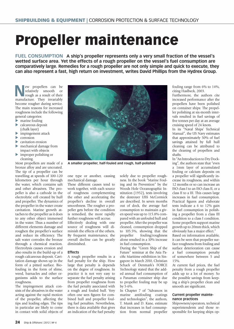
Propeller maintenance FUEL CONSUMPTION A ship’s propeller represents only a very small fraction of the vessel’s wetted surface area. Yet the effects of a rough propeller on the vessel’s fuel consumption are comparatively large. Remedies for a rough propeller are not only simple and quick to execute, they can also represent a fast, high return on investment, writes David Phillips from the Hydrex Group.
New propellers can be relatively smooth or rough as a result of their
manufacture. They invariably become rougher during service. The main reasons for increased roughness include the following general categories:
marine fouling �calcareous deposit �(chalk layer)impingement attack �corrosion �cavitation erosion �mechanical damage from �impact with objectsimproper polishing or �cleaning.
Most propellers are made of a bronze alloy and are uncoated. The tip of a propeller can be travelling at speeds of 100-120 kilometres per hour through the water, which contains salt and other abrasives. The pro-peller is also a cathode in the electrolytic cell created by hull and propeller. The dynamics of the propeller in the water create cavitation. Marine growth at-taches to the propeller as it does to any other object immersed in the water. Thus a number of different elements damage and roughen the propeller’s surface and reduce its effi ciency. The salt water corrodes the bronze through a chemical reaction. Electrolysis causes erosion and also results in the build-up of a rough calcareous deposit. Cavi-tation damage shows up in the form of a pitted surface. Bio-fouling in the form of slime, weed, barnacles and other or-ganisms adds to the surface roughness. The impingement attack con-sists of the abrasives in the water acting against the rapid motion of the propeller, affecting the tips and leading edges. The tips in particular are likely to come in contact with solid objects of
one type or another, causing mechanical damage. These different causes tend to work together, with each source of roughness complementing the other and accelerating the propeller’s decline in overall smoothness. The rougher a pro-peller gets before the condition is remedied, the more rapidly further roughness will accrue. Effectively dealing with one source of roughness will di-minish the effects of the others. By frequent maintenance, the overall decline can be greatly diminished.
EffectsA rough propeller results in a fuel penalty for the ship. How large that penalty is depends on the degree of roughness. In practice it is not very easy to separate the fuel penalty arising from propeller roughness from the fuel penalty associated with a rough and fouled hull. Very often one sees fi gures for com-bined hull and propeller foul-ing fuel penalties. Nevertheless, there is data available that gives an indication of the fuel penalty
solely due to propeller rough-ness. In the book “Marine Foul-ing and its Prevention” by the Woods Hole Oceanographic In-stitution (1952), tests involving the destroyer USS McCormick are described. In seven months out of dock, the average fuel consumption to maintain a giv-en speed was up to 115.8% com-pared with an unfouled hull and propeller. After the propeller was cleaned, consumption dropped to 105.5%, showing that the propeller fouling/roughness alone resulted in a 10% increase in fuel consumption. During the “Green Ship of the Future” seminar at the Asia Pa-cifi c Maritime exhibition in Sin-gapore in March 2010, Christian Schack of Denmark’s FORCE Technology stated that the add-ed annual fuel consumption of a Panamax container ship due to propeller fouling may be up by 5-6%. In Chapter 7 of “Advances in marine antifouling coatings and technologies”, the authors, T. Munk and D. Kane, estimate that increases in fuel consump-tion from normal propeller
fouling range from 6% to 14%, citing Haslbeck, 2003.Furthermore, the authors cite increased performance after the propellers have been polished on container ships: The propel-ler polishing at six-month inter-vals resulted in fuel savings of fi ve tonnes per day at an average cruising speed of 24 knots. In its “Naval Ships’ Technical Manual”, the US Navy estimates that approximately 50% of fuel savings attained by full hull cleaning can be attributed to the cleaning of propellers and shafts.In “An Introduction to Dry Dock-ing”, the authors state that “even a 1mm layer of accumulated fouling or calcium deposits on a propeller will signifi cantly in-crease its roughness, and within 12 months or so can increase an ISO class I to an ISO class II, or a class II to a III. This causes large increases in fuel consumption. Practical fi gures and elaborate tests indicate a 6 to 12% gain in fuel consumption in polish-ing a propeller from a class III condition to a class I condition. Some propellers support marine growth up to 20mm thick, which obviously has a major effect.” Based on information available, it can be seen that propeller sur-face roughness from fouling and surface deterioration can cause a fuel consumption penalty of somewhere between 5 and 15%.At current fuel prices, the fuel penalty from a rough propeller adds up to a lot of money. So the possible savings from keep-ing a ship’s propeller clean and smooth are signifi cant.
Current propeller mainte-nance practicesShipowners/operators, technical superintendents and those re-sponsible for keeping ships op-
A smaller propeller, half-fouled and rough, half-polished
24 Ship & Offshore | 2012 | No 4
SHIPBUILDING & EQUIPMENT | CORROSION PROTECTION & SURFACE TECHNOLOGY
SPI_004-12_10_33_20120514132504_504942.indd 24 14.05.2012 13:2 :4
erating effi ciently are aware that there is a fuel penalty associated with rough, fouled propellers. It is common for some mainte-nance measures to be in force to take care of this. These measures usually consist of scheduled propeller polish-ing. Often this is done only when a ship is dry-docked, which in most cases is too infre-quent to keep a propeller oper-ating at optimum effi ciency. Some vessel operators therefore schedule in-water propeller pol-ishing once or twice per year, which in most cases is still not frequently enough.While most ship propellers are bare metal, research has been done to try to remedy some of the propeller’s inherent prob-lems through the application of various coatings. While no uni-versal, fully workable and tested solution has yet been placed on the market, this line of research shows promise.If a propeller is not maintained frequently enough, economic and environmental problems ensue. The economic problem is the additional fuel penalty, which could have been avoided had the propeller been cleaned or polished sooner. This results in additional emissions of CO2, NOx, SOx and particulate matter. Restoring a very rough propeller to its original state (or close to it) requires grinding away a consid-erable amount of the material it-self, mostly copper but also zinc, nickel and other metals. While the amount of material removed from a single propeller may be relatively small, when multiplied across all the propellers used in the entire world fl eet, polishing can represent a signifi cant emis-sion of heavy metals and thus pollution and contamination of water column and sediment. Badly done polishing with a polishing disk or grinding wheel can create a rougher surface than that of the new propeller, leaving scratches that not only increase the propeller’s roughness but also facilitate attachment of foul-ing organisms. The infrequency and poor quality of cleaning or polishing are the major draw-backs of current propeller main-tenance practices.
If done early enough, the pro-peller can be cleaned with a ro-tating brush and abrasive mate-rial removing almost no metal, preventing the effects of cavita-tion damage from spiralling and avoiding the formation of cal-cium deposits. This early atten-tion can speed up the cleaning process considerably, extending the life span of the propeller and preventing the emission of heavy metals. This approach also eliminates the dangers of a roughened surface due to inex-pert grinding and polishing.Economically, the fuel saving from the timely cleaning of a propeller outweighs the cost. The cleaning can be combined with a general hull inspection by divers, making it even more economically viable. To establish the best practices for uncoated propeller mainte-nance, a routine for propeller cleaning must be found that per-mits rapid, easy (and therefore economical) propeller cleaning and is frequent enough to mini-mise the fuel penalty from pro-peller roughness and fouling. As stated in “Marine Propel-lers and Propulsion” by John Carlton, “With regard to the fre-quency of propeller polishing, there is a consensus of opinion between many authorities that it should be undertaken in ac-cordance with the saying ‘little and often’ by experienced and specialised personnel.” Of course propeller cleaning can be overdone. However, cleaning a propeller once every month or every two months would in many cases be optimal. If car-ried out this frequently, cleaning with a relatively soft brush and abrasives is adequate to keep a well-maintained propeller smooth enough for maximum fuel savings. It would prevent the accelerating spiral of cavi-tation damage plus corrosion plus fouling, which, if allowed to continue uninterrupted, re-quires major polishing with grinding or polishing wheel and the removal of a great deal of metal into the marine environ-ment should the polishing be carried out in the water. Clean-ing propellers “little and often” would be benefi cial to the envi-ronment as a minimum of cop-
per, zinc, nickel and other heavy metals would be ground off into the water.
Case study A recent experiment was car-ried out with a 134m-long cruise ship. The propellers were cleaned with a rotating brush alone, no grinding or polishing disk required, by a diver. It took him approximately 40 minutes to complete the cleaning of the ship’s two propellers. The foul-ing was not very heavy since the propeller is cleaned quite often. Calculations of subsequent fuel savings showed that on a 30-hour trip from Aruba to Barbados, the ship saved USD 2,100 com-pared with the same trip with a mildly fouled propeller. The ship consumes 1.6-1.7 tonnes of fuel/hour. The fuel saving as a result of cleaning the propeller was calculated at 6%. A 30-hour trip with an uncleaned propel-ler would have used 51 tonnes of fuel, equalling USD 35,700 at USD 700 per tonne. Six per cent of USD 35,700 is USD 2,142. In this case the propeller cleaning was carried out by a member of the crew. Had the propel-ler been cleaned by an outside company, it would not have cost more than about USD 2,000. So the cost of cleaning, even if car-ried out by a contractor, would have been recouped in the fi rst trip the ship took after cleaning. Since the propeller would not have had to be cleaned again for at least a month or two, the cost of the cleaning would have been recouped many times over.
Cost of cleaningObviously the cost of cleaning is a factor that cannot be overlooked. If the savings in fuel costs did not substantially outweigh the cost of propeller maintenance, then one would question the value of frequent propeller cleaning. The cost varies from one location to another and from one provider to another. The need for skilled and competent propeller clean-ing and polishing has already been stressed. Vendors usually charge per pro-peller size and number of blades. Polishing a four-blade, 6-metre propeller would cost somewhere between USD 1,900 and 3,000.
Polishing a six-blade, 8-metre propeller might cost between USD 3,100 and 4,000. One of the better propeller cleaning vendors charges 15-20% less for propeller cleaning (brush plus abrasives) than for full polishing with grinding or polishing disks. Which method is used depends on how rough the propeller is, and this is deter-mined largely by how often the propeller is polished or cleaned. As covered in the short case study above, the cost of the pro-peller cleaning can be recouped in the fi rst voyage the ship makes after the cleaning. Not only is it cheaper to clean than to polish, it also is economically advanta-geous. Cleaning takes less time than polishing.
ConclusionBest available practices for pro-peller effi ciency consist of the use of uncoated propellers with frequent, routine in-water clean-ing to prevent heavy fouling, the formation of a calcareous deposit layer and the spiralling damage of cavitation erosion and corrosion. Further research is needed into the use of strong-ly adherent, highly cavitation- and corrosion-resistant glass or ceramic reinforced coatings that can stand up to the extreme-ly challenging conditions in which propellers operate. Until such technologies have been perfected and proven in service, frequent light cleaning remains the best technology available.
ReferencesWoods Hole Oceanographic Institution: “Ma-rine Fouling and its Prevention“, US Naval In-stitute, (1952), pp 32-33
Christian Schack, FORCE Technology (presen-tation) March 2010. http://www.greenship.org/fpublic/green-ship/dokumenter/APM%20Singapore/7%20Force%20Technologies%20-%20Operation-al%20initiatives%20to%20reduce%20emis-sions%20from%20ships.pdf accessed 16 April 2012.
T. Munk, D. Kane, D. M. Yebra: “The effects of corrosion and fouling on the performance of ocean-going vessels: a naval architectural perspective,” Chapter 7 of “Advances in ma-rine antifouling coatings and technologies”, edited by Claire Hellio and Diego Yebra, Woodhead Publishing in Materials, (2009) p 161
Naval Sea Systems Command, Naval Ships’ Technical Manual, Chapter 081, “Waterborne Underwater Hull Cleaning of Navy Ships,” Re-vision 5, 1 Oct 2006, 081-2.1.1.1
David Martin et al. „An Introduction to Dry Docking“ http://www.angelfire.com/rnb/dry docking/home.htm, accessed March 2012.
John Carlton “Marine Propellers and Propul-sion (Second Edition)” Butterworth-Heine-mann Elsevier, (2007), p 383.
Ship & Offshore | 2012 | No 4 25
SPI_004-12_10_33_20120514132504_504942.indd 25 14.05.2012 13:2 :4
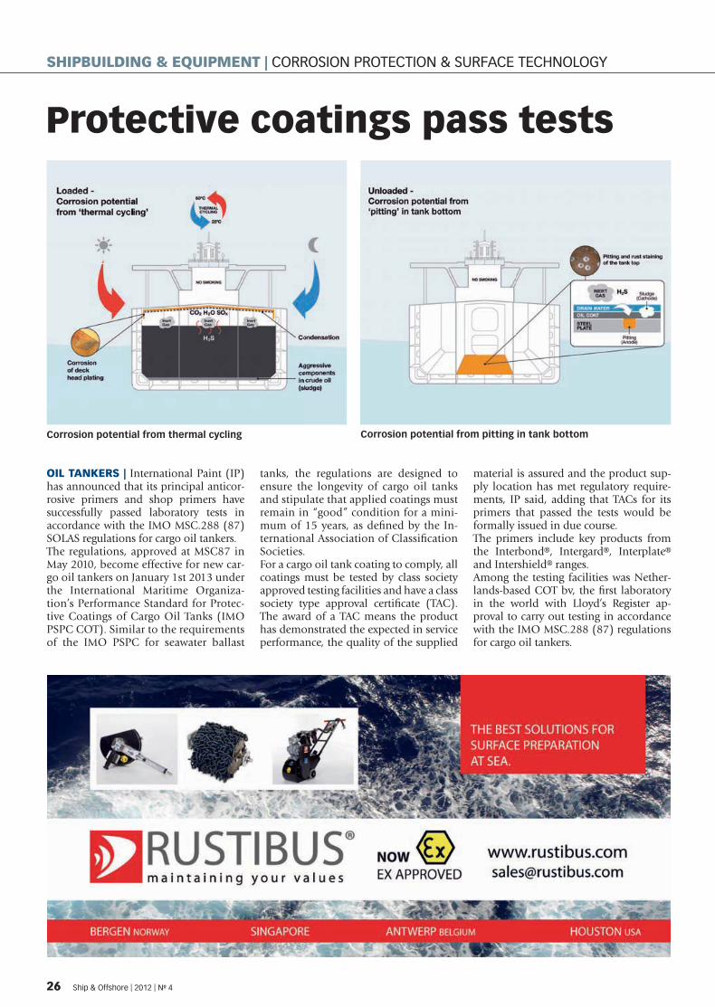
Protective coatings pass tests
OIL TANKERS | International Paint (IP) has announced that its principal anticor-rosive primers and shop primers have successfully passed laboratory tests in accordance with the IMO MSC.288 (87) SOLAS regulations for cargo oil tankers.The regulations, approved at MSC87 in May 2010, become effective for new car-go oil tankers on January 1st 2013 under the International Maritime Organiza-tion’s Performance Standard for Protec-tive Coatings of Cargo Oil Tanks (IMO PSPC COT). Similar to the requirements of the IMO PSPC for seawater ballast
tanks, the regulations are designed to ensure the longevity of cargo oil tanks and stipulate that applied coatings must remain in “good” condition for a mini-mum of 15 years, as defi ned by the In-ternational Association of Classifi cation Societies. For a cargo oil tank coating to comply, all coatings must be tested by class society approved testing facilities and have a class society type approval certifi cate (TAC). The award of a TAC means the product has demonstrated the expected in service performance, the quality of the supplied
material is assured and the product sup-ply location has met regulatory require-ments, IP said, adding that TACs for its primers that passed the tests would be formally issued in due course.The primers include key products from the Interbond®, Intergard®, Interplate® and Intershield® ranges. Among the testing facilities was Nether-lands-based COT bv, the fi rst laboratory in the world with Lloyd’s Register ap-proval to carry out testing in accordance with the IMO MSC.288 (87) regulations for cargo oil tankers.
Corrosion potential from thermal cycling Corrosion potential from pitting in tank bottom
26 Ship & Offshore | 2012 | No 4
SHIPBUILDING & EQUIPMENT | CORROSION PROTECTION & SURFACE TECHNOLOGY
SPI_004-12_10_33_20120514132504_504942.indd 2 14.05.2012 13:2 :4
Wet abrasion scrub testerQUALITY CONTROL | TQC (Thermimport Quality Control) has expanded its line of test equipment for the paint and coatings industry with a new wet scrub washability tester.Surfaces likely to be cleaned often such as table/desk tops, white goods, furniture, fl oors and walls, etc. need to be tested for their resistance against mechanical clean-ing with or without the use of detergents and checked on parameters including gloss retention, scratches, discolouration and other signs of mechanical wear, the Dutch company noted.It said the TQC scrub tester was a very fl ex-ible machine that could be used to test various materials, such as hiding power test charts, scrub panels, metal-, plastic-, or wood panels or parts, etc. For popular ISO and ASTM standards, the settings are preset in the machine but all parameters are fully fl exible. Cycle speed (1 to 60 str/min), stroke length (2 to 300mm), pump volume (0 to 3ml/min), number of cycles or test duration can all be set digitally by the operator. The machine has two separate dosing pumps, which allows simultaneous test-ing of two different media, according to TQC. The volume of the pumps can be set individually. An integrated marker makes it possible to set marks individually per channel to remind the operator when cer-tain damage on the surface has occurred. A fl exible acoustic signal is available to mark a (user preset) number of cycles. To meet the requirements of different stand-ards and tests, a wide range of tools such as wild boar brushes, nylon brush, spong-es, abrasive pad, etc. are available.
The TQC scrub tester
Bio-fouling controlECOSPEC | Singapore-based Ecospec has in-troduced what it calls the fi rst corrosion and bio-fouling control system using patented ultra-low-frequency (ULF) electromagnetic wave technology. This technology reduces energy consumption and lowers mainte-nance and operational costs with less envi-ronmental impact than alternate methods.Ecospec said its ElMag system was the fi rst corrosion control offering to use ULF elec-tromagnetic waves to promote a self-regener-ating, protective magnetite layer around sub-merged metal structures. When combined with BioMag (Ecospec’s ULF bio-fouling control system), the two fully protect against
corrosion and bio-fouling in the most envi-ronmentally friendly and cost-effective way available. According to Ecospec, the ElMag system is able to achieve the full “corrosion protection international acceptance criteri-on” of -800mV (against a Ag/AgCl electrode) with the following benefi ts over existing methods: cheaper installation and mainte-nance costs, less energy consumption, no consumable electrodes, no artifi cial coatings, no need for divers, less electrical current, easy one-point monitoring of equipment condi-tions, greater environmental sustainability and effectiveness in both freshwater and sea-water applications.
Hall A3 - 309
Are you looking for a lubricant helping rudder propellers achieve their full performance capacity and providing excellent protection of bearings, gear teeth and seals without harming the environment? Klüber Lubrication developed it: a gear oil complying with all requirements of leading thruster and propeller manufacturers. It is non-toxic, readily biodegradable, compatible with the sealing material and accepted for long-term use by a leading manufacturer of propeller shaft seals.
Klüberbio EG 2-150: the readily biodegradable high-tech lubricant.
www.klueber.com/[email protected]
High-performance oil to protect your seals and the environment.
your global specialist
Ship & Offshore | 2012 | No 4 27
SPI_004-12_10_33_20120514132504_504942.indd 2 14.05.2012 13:2 :0

Sophisticated FPSO unit for Brazilian oil fi eldCONVERSION FPSO (fl oating production, storage and offl oading) units used in Brazilian oil fi elds face harsh environments and operational challenges. The sophisticated FPSO Maersk Peregrino, which was converted from the VLCC tanker Maersk Nova, started operation in 2011 and now produces 100,000 barrels of oil per day.
T he one billion USD con-version of the tanker at Keppel Shipyard Ltd in
Singapore was completed in late 2010. Maersk Peregrino is chartered to Statoil for deploy-ment in the Peregrino fi eld in the Campos Basin, 85 km off the coast of Rio de Janeiro. First oil was produced in April 2011.Work on Maersk Peregrino in-volved the marine conversion of the Maersk Nova (built in 2008); installation and integra-
tion of the topside modules; assembly, installation and in-tegration of the APL internal turret; fabrication and installa-tion of the fl are tower, process pipe rack and helideck; and up-grading of the accommodation quarters.
Operational challengesOne reason for the complex-ity of the Maersk Peregrino is the texture of the oil extracted from the Peregrino fi eld. It is a
heavy viscous crude oil, which requires that production fa-cilities on board be highly spe-cialised. In simple terms, the Maersk Per-egrino must be able to heat up well fl uids to about 120°C to separate oil from gas, sand and water. When the oil is stored in the FPSO’s tanks, which have a total storage capacity of 1.6 million barrels (approximately. 250,000m³), it must be held at a temperature above 65°C
to keep from solidifying. This requires extreme amounts of power. To generate it, an opti-mised process unit with three steam boilers was installed on board. The power plant also supplies power to two Statoil drilling platforms in the Per-egrino oil fi eld.The boilers produce the equiva-lent of 72 MW of electricity, or approximately the daily power supply to more than 100,000 households. The unit’s big
The FPSO Maersk Peregrino is employed in Brazilian oil fi elds
28 Ship & Offshore | 2012 | No 4
SHIPBUILDING & EQUIPMENT | SHIP REPAIR & CONVERSION
SPI_004-12_10_33_20120514132504_504942.indd 2 14.05.2012 13:2 :12
need for electricity and steam does not mean that the Maersk Peregrino makes an oversize footprint on the environment, however. It has been construct-ed with an overall focus on safety and environmental legis-lation, according to its owner, Maersk FPSOs.
International projectThe conversion was super-vised by Copenhagen-based Maersk FPSOs and managed, both in Copenhagen and at the yard in Singapore, by Pe-ter Williams, senior director of special projects. Front-end engineering was carried out in Brazil, and the main engi-neering in Denmark, Norway, the UK, USA, India and Singa-pore. Parts for the processing facilities were supplied from the USA, Brazil and various European countries, and fab-ricated in Southeast Asia. The assembly and fi nal integra-tion of the hull, which was built in China, took place in Singapore.
Mooring The FPSO is moored using a submerged turret system, mounted forward with a moor-ing spread of 2 x 3 and 1 x 4 anchor piles connected to the turret table. The well fl uids and the produced water, gas and power for the wellhead plat-forms are transferred via the subsea risers and umbilicals through a swivel stack in the STP compartment, enabling the FPSO to freely weather-vane around the geostation-ary part of the turret under all conditions. The swivel stack includes three 12” production swivels, one 4” gas production swivel, three 10” water injec-tion swivels, one electrical swivel with fi ve 13.4Kv three-phase paths and one fi bre op-tic signal swivel.
Process facilitiesHeavy oil (14ºAPI) from each of the two wellhead platforms is pumped through two paral-lel fl owlines to the FPSO with suffi cient produced water to
be above the inversion point and keep viscosities low, thus aiding fl ow. Oil, gas and wa-ter are separated in two 50% parallel trains of three stages of separation and coalescing. The fi rst two stages are three-phase separators, with the oil pumped through an elec-trostatic coalescer and a low-pressure separator to meet the required crude product true vapour pressure and BS&W. Oil is metered before running down to the cargo tanks in the hull for later export via tank-ers. The off-gas is used as fuel gas, supplemented with diesel or crude to run the three boil-ers that produce steam, which drives the turbines for the main power generation and provides process heating. Produced wa-ter is de-oiled in hydrocyclones before being transferred back to the wellhead platforms for injection or recycling. If re-quired, the produced water is further cleaned in a compact fl otation unit for occasional disposal overboard.
Simulation studies of the hook-up procedureThe hook-up between the turret and the FPSO is a very critical and costly operation. To ensure a safe hook-up with Maersk Per-egrino, Maersk FPSOs assigned Denmark-based FORCE Tech-nology to evaluate and perform simulation studies of the proce-dure. The simulations were in-strumental in deciding the tug size needed during the hook-up between the FPSO and STP buoy at the Peregrino oil fi eld. They were performed with the help of in-house mathematical and visual simulator models of the FPSO.
Wind tunnel testingThe tests started in one of FORCE Technology’s fi ve wind tunnels, to determine the wind and current forces acting on the FPSO. This is crucial in the structural design of turret and moorings because the precision of the positioning is infl uenced by wind gusts and squall. In the study, the wind was mod- �
G+H Marine GmbHBredowstraße 10 | 22113 Hamburg
Phone: +49 40 73343-2200 | Fax: +49 40 73343-2299 | E-Mail: [email protected]
You will fi nd more activities on the internet.
• Engineering
• HVAC
• New building
• Conversion/repair
We solve problems all over the world – talk to us!
www.guh-marine.com | www.gruppe-guh.de
Your expert inship outfi tting
Ship & Offshore | 2012 | No 4 29
SPI_004-12_10_33_20120514132504_504942.indd 29 14.05.2012 13:2 :19

elled as gusty with a spectral density described by the Frøya spectrum.The original objective of the wind tunnel tests was to ob-tain wind and current loads for the structural design of turret and moorings; however, the results of the simulations were also needed to help establish a mathematical model of all en-vironmental forces acting on the vessel.
Establishing the mathematical modelTo establish the mathemati-cal model, the fi rst-order mo-tions and wave drift forces of the vessel were calculated using FORCE Technology’s in-house software: the 3D frequency do-main radiation-diffraction pro-gram S-OMEGA. This software uses a “Green Function ap-proach” with a linearised free surface to calculate the velocity potentials on the panels defi n-ing the underwater hull surface. The surface pressures are com-puted from the time derivatives of the velocity potentials at the hull surface and integrated to
compute the wave fi eld, wave excitation forces, added mass and wave radiation damping. The computations include the effect of fi nite water depth on both the relationship between wave frequency and length and the pressure refl ection at the sea bottom.By combining the aerodynam-ic data from the wind tunnel tests with the hydrodynamic forces acting on the FPSO, it was possible to develop two mathematical ship models of the Peregrino FPSO: one for the hook-up condition with a draught of 12m bow and aft, and another for the riser pull-in condition with a draught bow and aft of 6m and 10m, respectively. The models were generated using an in-house shipyard software – a ma-noeuvring prediction program whose models are based on a neural network trained upon a large number of ships in FORCE Technology’s database – along with wind tunnel tests and seakeeping calculations made for the present ship in the two draught conditions.
Fast-time simulationOnce the mathematical model was developed, fast-time simu-lations were carried out for the hook-up operation and riser pull-in operation. All state vari-ables were recorded during the simulations. Both the hook-up and riser pull-in simulations were done with initial operation criteria of two knots current going south/south-west, wind speed of 10 m/s and irregular waves with a signifi cant wave height of 2m, described through a double-peak spectrum. Simu-lations were also carried out for wind speeds of 12 m/s with unaltered waves and current compared with the operation criteria, in order to verify whether the operation criteria were close to the criti-cal limit.The hook-up simulations fo-cused on the ability to move the vessel to a fi xed position above the submerged turret and keep it there during the opera-tion. Making the scenarios as realistic as possible, the simula-tions covered three-hour peri-
ods to confi rm the tugs’ ability to bring the vessel in position above the turret and maintain the position for long intervals. As regards tolerance, the most critical phase is just before the connection starts since the tur-ret and its moorings, after con-nection, will gradually help in maintaining the position as it is being pulled in.Subsequently, FORCE Technol-ogy evaluated the tug size need-ed to perform the riser pull-in. This is the operation in which the vessel is connected to the turret and is pulling in and con-necting the risers. Maintaining heading during this operation is crucial. During simulation of the riser pull-in, the FPSO was moored to the turret, and its mooring system provided the right response in all degrees of freedom relevant to the assign-ment under the infl uences of wind, waves and current. Both the hook-up operation and evaluation of tug size were car-ried out based on detailed met-ocean data from the Peregrino fi eld for the time period of the installation.
Maersk Peregino Length overall 332.85m
Length overall incl. helideck 345.22m
Breadth 58m
Depth 31m
Deadweight 307,284 dwt
Hull Former double hull product tanker, Maersk NovaBuilt 2008 at Dalian Shipbuilding Industry Co Ltd, China
Converted to FPSO 2009-2010 at Keppel Shipyard, Singapore
Accommodation 100 persons
Primary lifesaving 2x100 persons lifeboat
Fassmer CL-T 13.2 with Nadiro davit
Helideck Sikorsky S-92
Cranes Three cranes with lifting capacity of 36 t @ 50m and 18 t @ 60m
One crane with lifting capacity of 15 t @ 30m and 10 t @ 40m
Storage 1,600,000 barrels
Liquid production 350,000 barrels per day
Oil production 100,000 barrels per day
Gas production 7.3 mmscf/day
Water injection 300,000 bw /day
Power generation 72 MW
TECHNICAL DATA �
The FPSO was converted in Singapore
30 Ship & Offshore | 2012 | No 4
SHIPBUILDING & EQUIPMENT | SHIP REPAIR & CONVERSION
SPI_004-12_10_33_20120514132504_504942.indd 30 14.05.2012 13:2 :22

As the premier ship repairer and market leader in FPSO, FSO and FSRU Conversions, we have come to be known for our flexibility, quality, innovation, safety excellence and commitment to customers.
Keppel Shipyard Limited (A member of Keppel Offshore & Marine Limited) 51 Pioneer Sector 1 Singapore 628437 Tel: (65) 68614141 Fax: (65) 68617767 Email: [email protected] www.keppelshipyard.com
Specialist in repair and conversion
SPI_004-12_10_33_20120514132504_504942.indd 31 14.05.2012 13:2 :2
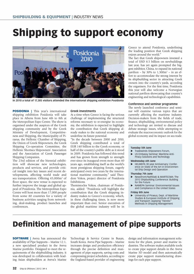
POSIDONIA | This year’s international shipping exhibition Posidonia will take place in Athens from June 4th to 8th at the Metropolitan Expo Centre. The show is organised under the auspices of the Greek shipping community and by the Greek Ministry of Development, Competitive-ness and Shipping, the Municipality of Pi-raeus, the Hellenic Chamber of Shipping, the Union of Greek Shipowners, the Greek Shipping Co-operation Committee, the Hellenic Shortsea Shipowners’ Association and the Association of Greek Passenger Shipping Companies. The 23rd edition of the biennial exhibi-tion will showcase new technologies, products and services, and provide criti-cal insight into key issues and recent de-velopments, affecting world trade and sea transportation. Offering 45,000m2 of fl oor space, the new venue is expected to further improve the image and global ap-peal of Posidonia. The Metropolitan Expo Centre will host more than 17,000 people from some 80 countries for a variety of business activities ranging from network-ing, deal-making, product launches and conferences.
Greek investments At a time when Greece is facing the serious challenge of implementing the structural reforms necessary to re-energise its econo-my, the exhibition is expected to highlight the contribution that Greek shipping al-ready makes to the national economy and underline its future potential. “In the decade between 2000 and 2010, Greek shipping contributed a total of EUR 140 billion to the Greek economy, or half of the country’s public debt as it stood in 2009. Posidonia has followed this trend and has grown from strength to strength ever since its inaugural event more than 40 years ago, establishing itself as the world’s most prestigious shipping forum, eagerly anticipated every two years by the interna-tional maritime community,” said Theo-dore Vokos, project director of Posidonia Exhibitions. Themistocles Vokos, chairman of Posido-nia, added: “Posidonia will highlight the contribution that the Greek shipping in-dustry makes to Greece’s economy, which, in these challenging times, is now more important than ever. Senior executives of the global maritime industry will be in
Greece to attend Posidonia, underlining the leading position that Greek shipping enjoys around the world.”The fact that Greek shipowners invested a total of USD 8.5 billion on newbuildings last year, has yet again prompted the big-gest exhibitor, China, to expand its national pavilion – by 30% to 1,300m2 – in an ef-fort to accommodate the strong interest by its shipbuilding sector in attracting Greek owners into the country‘s yards, according the organisers. For the fi rst time, Posidonia this year will also welcome a Norwegian national pavilion showcasing that country’s engineering and technological capabilities.
Conference and seminar programmeThe newly launched conference and semi-nar will examine various topics that are currently affecting the maritime industry. Decision-makers from the fi elds of trade, fi nance, shipbuilding, environmental policy and technology are invited to discuss and debate strategic issues, while attempting to evaluate the macroeconomic outlook for the global economy and its impact on sea trade.
In 2010 a total of 17,385 visitors attended the international shipping exhibition Posidonia
Shipping to support economy
Defi nition and management of pipe supports
SOFTWARE | Aveva has announced the availability of Pipe Supports – Marine 12.1, a new specialised product in the Aveva Marine portfolio. Designed to meet the re-quirements of the shipbuilding industry, it was developed in collaboration with lead-ing Asian shipbuilders at Aveva’s Marine
Technology & Service Centre in Busan, South Korea. Aveva Pipe Supports – Marine increases design and production effi ciency through the precise defi nition and man-agement of pipe supports, saving costs and compressing project schedules, according to the England-based provider of engineering
design and information management solu-tions for the plant, power and marine in-dustries. The software makes available tools to create pipe support details in the Aveva Marine 3D model and then automatically create pipe support manufacturing draw-ings for each pipe support.
Tuesday 5th June Tradewinds Shipowners Forum, �US Embassy Seminar: Maritime Anti- �Piracy Solutions and Technology
Wednesday 6th June HELMEPA 30 year Anniversary: Confer- �ence on State of the Art in Environmen-tal Ship Design and Operation
Thursday 7th June Newsfront/Naftiliaki & MARTECMA: The �2012 Shipbuilding Conference: Building for the FutureNAMEPA Seminar: Environmental Issues �and Compliance in the United States
Friday 8th June University of Piraeus, Dept. of Maritime �Studies & European Institute of Shipping and Transport: Applying “Heretic” Methods in Shipping Management
32 Ship & Offshore | 2012 | No 4
SHIPBUILDING & EQUIPMENT | INDUSTRY NEWS
SPI_004-12_10_33_20120514132504_504942.indd 32 14.05.2012 13:2 :2
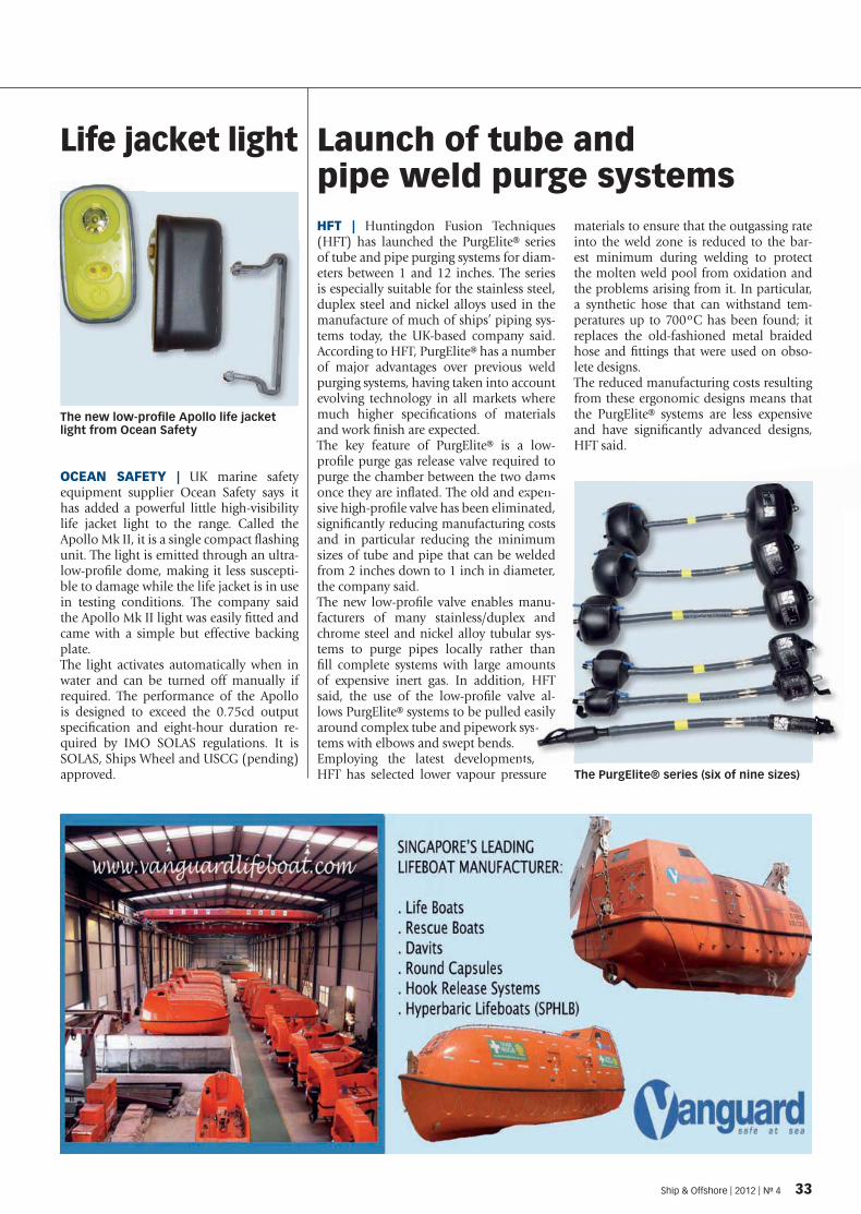
Launch of tube and pipe weld purge systems
The new low-profi le Apollo life jacket light from Ocean Safety
HFT | Huntingdon Fusion Techniques (HFT) has launched the PurgElite® series of tube and pipe purging systems for diam-eters between 1 and 12 inches. The series is especially suitable for the stainless steel, duplex steel and nickel alloys used in the manufacture of much of ships’ piping sys-tems today, the UK-based company said. According to HFT, PurgElite® has a number of major advantages over previous weld purging systems, having taken into account evolving technology in all markets where much higher specifi cations of materials and work fi nish are expected.The key feature of PurgElite® is a low-profi le purge gas release valve required to purge the chamber between the two dams once they are infl ated. The old and expen-sive high-profi le valve has been eliminated, signifi cantly reducing manufacturing costs and in particular reducing the minimum sizes of tube and pipe that can be welded from 2 inches down to 1 inch in diameter, the company said.The new low-profi le valve enables manu-facturers of many stainless/duplex and chrome steel and nickel alloy tubular sys-tems to purge pipes locally rather than fi ll complete systems with large amounts of expensive inert gas. In addition, HFT said, the use of the low-profi le valve al-lows PurgElite® systems to be pulled easily around complex tube and pipework sys-tems with elbows and swept bends.Employing the latest developments, HFT has selected lower vapour pressure
materials to ensure that the outgassing rate into the weld zone is reduced to the bar-est minimum during welding to protect the molten weld pool from oxidation and the problems arising from it. In particular, a synthetic hose that can withstand tem-peratures up to 700ºC has been found; it replaces the old-fashioned metal braided hose and fi ttings that were used on obso-lete designs.The reduced manufacturing costs resulting from these ergonomic designs means that the PurgElite® systems are less expensive and have signifi cantly advanced designs, HFT said.
Life jacket light
OCEAN SAFETY | UK marine safety equipment supplier Ocean Safety says it has added a powerful little high-visibility life jacket light to the range. Called the Apollo Mk II, it is a single compact flashing unit. The light is emitted through an ultra-low-profile dome, making it less suscepti-ble to damage while the life jacket is in use in testing conditions. The company said the Apollo Mk II light was easily fitted and came with a simple but effective backing plate.The light activates automatically when in water and can be turned off manually if required. The performance of the Apollo is designed to exceed the 0.75cd output specifi cation and eight-hour duration re-quired by IMO SOLAS regulations. It is SOLAS, Ships Wheel and USCG (pending) approved. The PurgElite® series (six of nine sizes)
amspenand exp
liminaturing cominimbe welddiame
es maplex a
ular her thamouon, Halve d easys-
nts,
pen-ted,osts
mumded eter,
anu-andsys-han untsHFT
al-asily -
Ship & Offshore | 2012 | No 4 33
SPI_004-12_10_33_20120514132504_504942.indd 33 14.05.2012 13:2 :32
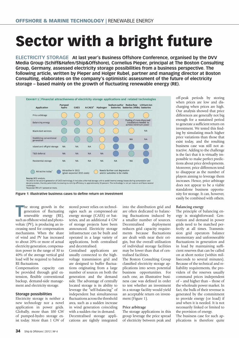
Sector with a bright futureELECTRICITY STORAGE At last year’s Business Offshore Conference, organised by the DVV Media Group (Schiff&Hafen/Ship&Offshore), Cornelius Pieper, principal at The Boston Consulting Group, Germany, assessed electricity storage possibilities from a business perspective. The following article, written by Pieper and Holger Rubel, partner and managing director at Boston Consulting, elaborates on the company’s optimistic assessment of the future of electricity storage – based mainly on the growth of fl uctuating renewable energy (RE).
The strong growth in the generation of fl uctuating renewable energy (RE),
such as offshore wind and photo-voltaic (PV), is producing an in-creasing need for compensation mechanisms. When the share of wind and PV has increased to about 20% or more of actual electricity generation, compensa-tion power in the range of 30 to 40% of the average vertical grid load will be required to balance RE fl uctuations.Compensation capacity can be provided through grid ex-tension, fl exible conventional backup, demand-side manage-ment and electricity storage.
Storage possibilitiesElectricity storage is neither a new technology nor a novel application in power grids. Globally, more than 100 GW of pumped-hydro storage ex-ist today. More than 1 GW of
stored power relies on technol-ogies such as compressed-air energy storage (CAES) or bat-teries, and an additional 4 GW of storage projects have been announced. Electricity storage infrastructure can be built and operated in a large variety of applications, both centralised and decentralised.Centralised applications are usually connected to the high-voltage transmission grid and are designed to buffer fl uctua-tions originating from a large number of sources on both the generation and the demand side. The advantage of centrally located storage is its ability to leverage the “self-balancing” of independent but simultaneous fl uctuations across the threshold area, such as a sudden increase in wind generation coinciding with a sudden rise in demand. Decentralised storage appli-cations are tightly integrated
into the distribution grid and are often dedicated to balanc-ing fl uctuations induced by a smaller number of sources. Decentralised deployment reduces grid capacity require-ments because fl uctuations are dealt with near their ori-gin, but the overall utilisation of individual storage facilities may be lower than that of cen-tralised facilities.The Boston Consulting Group classifi ed electricity storage ap-plications into seven potential business opportunities. For each one, an illustrative busi-ness case was defi ned in order to test whether an investment in a storage facility would yield an acceptable return on invest-ment (Figure 1).
Price arbitrageThe storage applications in this group leverage the price spread of electricity between peak and
off-peak periods by storing when prices are low and dis-charging when prices are high. Our analysis showed that price differences are generally not big enough for a sustained period to generate a suffi cient return on investment. We tested this fi nd-ing by simulating much higher price variations than those that exist today, and the resulting business case was still not at-tractive. Adding to the challenge is the fact that it is virtually im-possible to make perfect predic-tions about price developments. Moreover, price differences tend to disappear as the number of players aiming to leverage them increases. Hence, price arbitrage does not appear to be a viable standalone business opportu-nity for storage. It can, however, easily be combined with others.
Balancing energyThe principle of balancing en-ergy is straightforward: Gen-eration and demand in power grids need to be matched per-fectly at all times. Transmis-sion grid operators balance momentary and unforeseeable fl uctuations in generation and in load by maintaining suffi -cient reserves that can be called on at short notice (within mil-liseconds to several minutes). Because of the technical and re-liability requirements, the pro-viders of the reserves usually command prices independent of – and higher than – those of the wholesale power market. In fact, the bulk of their revenue is generated by the commitment to provide energy (or load) if and when it is needed. It is not necessarily linked or limited to the provision of energy. The business case for such ap-plications is therefore quite
Figure 1: Illustrative business cases to defi ne return on investment
34 Ship & Offshore | 2012 | No 4
OFFSHORE & MARINE TECHNOLOGY | RENEWABLE ENERGY
SPI_004-12_34_50_20120514145921_504941.indd 34 14.05.2012 14:59:42
attractive. At recent price lev-els, large storage facilities us-ing pumped hydro and CAES achieve an attractive return on investment, especially when they provide negative balanc-ing energy (for example, to mitigate a sudden electricity surplus). The storage facility can use surplus energy taken from the grid at night, for ex-ample, and sell it on the power market at peak prices at a later time. This option of being double-paid is not available to other providers of balancing energy. Although prices have fallen recently due to increas-ing competition, The Boston Consulting Group expects sta-ble price levels.
Black-start servicesBlack start refers to the initial power supply required to re-build a power grid after a full blackout. All highly developed power grids require dedicated, reliable power sources to pro-vide this emergency energy. Providing black-start services is not a prime business oppor-tunity. Some countries require certain power plants to provide their own black-start capacity, reducing the opportunities for external providers. However, it deserves consideration as a source of additional revenues. It is characterised by low-fre-quency utilisation but is tech-nically easy to implement.
Stabilising conventional generationAny energy-generation system must be able to react fl exibly to changes in load and genera-tion. Some of this fl exibility is provided by balancing energy, as described above. Longer fl uctuations — lasting hours or days — can be accommo-dated by ramping conventional power generation up and down or by throttling peaks in renew-able generation. But with RE-induced fl uctuations growing, these procedures are becoming increasingly uneconomical. Given the large amounts of power and energy required to buffer conventional genera-tion assets, large-scale storage is most appropriate for this appli-cation. For example, CAES can provide an IRR of more than 15% in certain scenarios by reducing ramping costs and by increasing uptime of conven-tional generation assets. Note that this calculation assumes an integrated view of several assets, rather than viewing each asset as an isolated profi t centre.
Island and off-grid storageToday, diesel generators ensure electricity generation in many island and off-grid settings, sim-ply because there is no feasible alternative. This is a sizable mar-ket, representing an installed fl eet of 600 GW of diesel gen-eration capacity [1]. Electricity
storage in combination with RE sources, especially wind and PV, not only offers an attractive fi -nancial upside but also entails an impressive reduction in CO2 emissions. Even when the cost of an emergency backup diesel generator is included, a positive return on the overall investment can be realised. Although bat-teries are well-positioned for this storage application, the ideal technology is likely to vary according to the specifi c on-site conditions.
T&D deferralTransmission and distribution (T&D) deferral uses electric-ity storage as a means of either avoiding or deferring an invest-ment in grid infrastructure. Generally, the additional ca-pacity required and the length of the power line needing upgrade determine whether setting up a storage facility is more attractive than upgrading the power line.Batteries are the technology of choice for this application. Installed near the load, they discharge at peak times and charge at off-peak times. Al-though particularly useful in lower-power situations, initial calculations have shown that this application can satisfy certain higher-power require-ments, such as optimising the linkage of a wind park to the transmission grid. Besides the
pure economics, government subsidies incentivising the feed-in of less-fl uctuating wind power are a key driver of such installations.
Residential storageResidential storage is frequent-ly discussed in connection with the development of residential PV installations. A small lith-ium-ion battery stores excess electricity that is generated at around noon and retains it for the afternoon and evening, in-creasing self-consumption and reducing the strain on the dis-tribution grid. It is unlikely that subsidies for self-consumption will increase relative to conventional feed-in. However, with cost degression in PV modules and batteries, and grid parity within reach in many countries, self-supply lev-eraging RE and batteries can be-come an attractive alternative to (increasing) retail energy costs. The fi rst products are on the market, and we expect related applications, such as neigh-bourhood storage, to emerge in the future. Although seem-ingly a small step forward, these business models stand to have a substantial impact on the cur-rent retail-power business.
Key insightsOnly a thorough assessment of specifi c projects can provide a reliable basis for invest- �
Leave your liabilities to the experts
Dynamic P&I solutions for a dynamic industry
www.shipownersclub.com
The Shipowners’ Club
Ship & Offshore | 2012 | No 4 35
SPI_004-12_34_50_20120514145921_504941.indd 35 14.05.2012 14:59:44

ment decisions; however, sev-eral key insights can be drawn from our analyses. Firstly, electricity storage ap-plications can, under favorable conditions, be profi table today. Cost degressions, especially in stationary batteries, will signifi -cantly improve profi tability in a number of applications. Secondly, although any storage technology can theoretically be used for almost any applica-tion, performance character-istics and costs point to some obvious combinations, such as off-grid settings and batteries. Additionally, under favorable conditions, large-scale stor-age technologies are already fi nancially attractive, while de-centralised applications using batteries will become so within the next fi ve years or so.Thirdly, the successful operation of a storage facility is a complex task. Making the most of such an investment requires sophis-ticated operational optimisa-tion and experience, suggesting strong fi rst-mover advantages for the operators of new facilities.
The market for storageTo forecast the potential of the seven business opportunities, the market potential of the electricity-storage applications through 2030 was calculated. On top of the approximately 100 GW of storage that exists today, we forecast an addition-al market potential for approxi-mately 330 GW. This translates
into an additional cumulated investment need of approxi-mately EUR 280 billion to 2030, including replacement. Balancing power will drive ap-proximately one-third of the market potential. Batteries will account for almost 50% of this market in terms of fi nancial investment, although they will represent a very small part of the storage capacity needed by 2030 (Figure 2).We believe that the storage busi-ness will gradually grow over the next few years, driven by the increasing penetration of RE generation and the need to manage fl uctuations, and by the maturity of the key storage technologies, especially batter-ies. Today, the storage market is worth about EUR 1 billion per year. We expect annual global market volumes of EUR 2 bil-lion to EUR 3 billion per year in the next few years, increasing to EUR 4 billion to EUR 6 bil-lion per year after 2015 and to more than EUR 10 billion per year after 2020.Our calculations were made purely from a cost perspective, omitting the potential ben-efi cial effects of storage-related regulation, which has the po-tential to boost the storage busi-ness well beyond the forecasted volumes if implemented.
Potential stakeholders Electricity storage offers numer-ous business opportunities to a wide range of stakeholders. Ob-
vious market participants are utilities and technology provid-ers. However, other players, in-cluding the following, may be attracted to a new segment of the energy business in which stakes have yet to be claimed.
Power generation players: �In addition to power genera-tion companies such as utili-ties, power system stakeholders such as municipalities and grid operators may benefi t from running electricity storage fa-cilities to mitigate grid bottle-necks or to better leverage their existing generation assets.
Suppliers: Business oppor- �tunities exist for raw-material sellers, battery producers, and technology companies that serve the energy industry.
End-product companies: �Energy storage capacity could enable these companies to pro-vide more innovative products to their clients and to enhance their own operations. In partic-ular, many automotive OEMs are considering decentralised e-car batteries as virtual storage facilities.
Identifying the opportunitiesAlthough each prospective stakeholder will identify and evaluate potential storage-relat-ed business opportunities from a different perspective, The Bos-ton Consulting Group proposes a general four-step approach:
Thoroughly understand the �storage technologies and their potential applications and op-
erational models. There are many independent parameters involved in determining the operational profi tability of in-dividual applications.
Analyse and quantify the �relevant end market. Assess key trends, market drivers, and growth factors. Then, realisti-cally quantify market demand, starting from the relevant ap-plications and taking into ac-count regional focus and spe-cifi c regulations.
Identify the technology that �best meets market demand. Given the technical require-ments of the particular appli-cation, select the most suitable storage technology. Alternative-ly, a company may choose to leverage a particular technolo-gy because of existing in-house capabilities or in response to external factors such as govern-ment or fi nancial incentives. In that case, the potential applica-tions of the chosen technology must be identifi ed.
Determine the implications �for the relevant market of each stakeholder. Technology pro-viders should analyse storage technology road maps in order to determine and assess the re-lated investment.Electricity storage offers an ex-citing option for a much wider range of stakeholders than is generally assumed. Corporate electricity-storage strategies based on a thorough assessment will have the best chance of suc-ceeding. Because the fi nancial return on a storage investment is strongly contingent on fi nd-ing a location with a suitable set of parameters, we believe there is a clear fi rst-mover advantage for the operators of storage fa-cilities. It is therefore essential to evaluate opportunities in this sphere quickly.
Remarks[1] This is the cumulated market for 1980 to 2010, representing an installed capacity of diesel gen-erators with a nominal power of 500 kW or greater and assum-ing a 30-year generator lifetime. See Power Systems Research at http://www.powersys.com/.
This article is based on “Revisiting Energy Storage: There Is a Business Case”, a BCG report, published in February 2011.
Figure 2: Market potential of storage technologies
36 Ship & Offshore | 2012 | No 4
OFFSHORE & MARINE TECHNOLOGY | RENEWABLE ENERGY
SPI_004-12_34_50_20120514145921_504941.indd 3 14.05.2012 14:59:45

Wind turbine project KONGSBERG | The Norwegian marine technology company Kongsberg Maritime is head-ing a 22 million NOK project aimed at developing a fl ex-ible instrumentation system for wind turbines to make offshore wind power more competitive. Called Windsense, the project was initiated in collaboration with the instrumentation clus-ter NCEI (Norwegian Centres of Expertise Instrumentation).It will make wind turbines more effective by reducing unplanned shutdowns, thereby enhanc-ing power plants’ reliability. It will also enable the turbines to be run temporarily at a lower capacity in anticipation of re-quired maintenance, further cutting expensive downtime.The three-year project, which got under way in February, has received a NOK 10 million grant from the Research Council of Norway’s RENERGI programme.
A key challenge is adapting the maritime oil and gas sector’s maintenance equipment and methods for use on offshore wind turbines, Kongsberg Mari-time said. Cost-effective opera-tion will require new technology enabling greater remote control and monitoring of the turbines. It will also require durable, re-liable instruments to monitor the operation and components in harsh environments at sea. “This system will primarily be an instrument for monitoring the technical condition of the wind turbine and the life cycle of the components used,” re-marked the project manager, Oddbjørn Malmo of Kongsberg Maritime, Lade. Along with Kongsberg Maritime, the participants of the Wind-sense collaboration are Statoil, NTE, Light Structures, Trollhet-ta, NTNU, HiST, SINTEF Energy Research and MARINTEK.
Jack-up barge craneDRYDOCKS WORLD | Pro-duction documentation and construction of a new jack-up barge crane for offshore build-ing duties is nearing com-pletion by UAE shipbuilder Drydocks World. FORAN, de-veloped by the Spanish engi-neering and technology group Sener, has been the CAD/CAM system used in the engi-neering.Called SEP – SAMRAT, the vessel is a non-propelled self-elevating platform having a total lifting capacity of almost 2,950 tonnes with the help of four legs and the correspond-ing jacking system, according to Sener. It is equipped with a central main crane and auxil-iary systems, such as mooring winches, diesel generators, hy-draulic power packs and trans-fer pumps.The offshore barge has a length overall of 49.5m, breadth of
25m and draught of 2.5m. It has been classifi ed by Bureau Veritas with class I �HULL �MACH, Offshore Self-Ele-vating Unit, Special Service/Construction Works, Indian Coastal – Summer Zone Tran-sit, �ALM.Leg height is 60m. The el-evating spuds, which are pipe sections with 2.2m of outer diameter and 45mm of thickness, are actuated individually by a hydraulic jacking system, each of them capable of 1,055 tonnes of lifting force. The main crane is a Manitowoc 1800, with a rated capacity of 600 tonnes and a boom length of 97.5m. There are two generators, rated 335kW each, as well as an emergency generator rated 130kVA. The mooring is en-sured by means of six winches, each one rated at 25 tonnes of pulling force.
keeping the course
hamburg4 – 7 sept 2012
You can also join us atSMM India 2013 4–6 april, mumbai
Book your stand now at smm-india.com/exhibit
facebook.com/SMMfair twitter.com/SMMfair youtube.com/SMMfair
SPI_004-12_34_50_20120514145921_504941.indd 3 14.05.2012 14:59:4

Analysis of lifting operations at offshore wind farms VESSEL OPTIMISATION Offshore wind turbines are becoming larger and more sophisticated, and they are being installed at ever greater water depths. So the monopiles carrying them must increase in size as well. This chain reaction also affects the vessels used in transport, installa-tion and lifting operations. It is thus vital that the cranes and vessels involved be modifi ed and optimised, writes Kristian Agdrup, head of department at OSK-Offshore, Denmark.
In 2010, the average offshore wind turbine capacity was 2.9 MW; today the fi gure is
3.6 MW. It is estimated that the average capacity of offshore wind turbines will be 6 MW by 2015.Despite the increase in size and water depths of wind farm installations, the range of available installation ves-sels has been rather limited, leaving operators little choice. Recently, however, many new crane vessels have been built or are under construction/con-version, so now installation vessels can compete not only in availability but also in per-formance. The requirements for the in-stallation vessels can vary from wind farm to wind farm and
location to location. The water depth, seabed, as well as wind, wave and current conditions infl uence the choice of vessel and determine whether a jack-up, heavy lift vessel (HLV) or a vessel equipped with dynamic positioning (DP) capability should be used. The load-off and lifting operations at sea require particular attention because of the large loads lift-ed, but it is usually the water depth that plays the decisive role when selecting the right vessel since jack-up vessels have a natural limit on the jacking height. Using the top-end software from ANSYS AQWA, a sea-keeping analysis can assess the lifting capacity and preci-sion when lifting and placing
the monopile, transition piece and turbine. With the right in-stallation vessel and a reliable seakeeping and a lifting capac-ity analysis, the operational window can be prolonged and the installation process can be carried out in a wide range of sea states.
Numerical seakeeping Classifi cation societies require documentation for safe opera-tion from the operator prior to the load-off/lifting opera-tion and installation at an off-shore wind farm. Since it is not viable to investigate the boundaries of such operations by on-site testing, this docu-mentation must be provided using simulations in a reliable computer model.
With the AQWA software from ANSYS it is possible to analyse the environmental conditions, predict the ship’s response, specify the performance cri-teria and optimise the design for a specifi c purpose. AQWA is a 3D diffraction multi-body panel code used for numeri-cal seakeeping analysis. A nu-merical seakeeping analysis in frequency and time domain can determine the conditions under which the vessel is able to perform a given operation. Additionally, the software can be used to study lifting opera-tions, perform mooring ana-lyse as well as calculate hook load forces for crane lifts. OSK-Offshore was recently asked to carry out the overall modifi cation design on an A-frame on board the heavy lift vessel Svanen. The A-frame was to be used to lift a mono-pile off a barge moored inside the horseshoe-shaped pon-toons of the HLV. By using the AQWA software, it was possi-ble to analyse the hook load forces and thereby determine the dynamic amplifi cation factor for the lift, and also to optimise the main lifting ar-rangement.
The complexity of load-off at seaThe challenge of load-off at sea is the multi-body motion and coordination between HLV/barge and crane – both of which are affected by wind, waves and current – as well as the dynam-ic loads from the cargo during the lifting operation.As mentioned above, the clas-sifi cation societies require
The heavy-lift vessel Svanen is used for the accurate installation of offshore wind parks
38 Ship & Offshore | 2012 | No 4
OFFSHORE & MARINE TECHNOLOGY | RENEWABLE ENERGY
SPI_004-12_34_50_20120514145921_504941.indd 3 14.05.2012 14:59:4
documentation of worst-case scenarios, i.e. the worst combi-nation of wind, waves and cur-rent occurring in the defi ned weather window with respect to impact on the lifting op-eration. The vessel and crane must be dimensioned in ac-cordance with the class rules. With AQWA it is possible to calculate environmental forces on complicated structures and thereby simulate motions and accelerations in the complex load-off situation; and it was possible for OSK-Offshore to optimise the design of the A-frame to meet these require-ments while at the same time minimising the amount of steel used in the modifi cation of the crane.
DP in offshore wind operationsThe possibility of using moor-ing lines to keep an HLV in po-sition should be investigated, as a mooring system must be
regarded as more robust than a DP system. The large thruster power needed to keep an HLV in position with DP can be very costly in fuel consumption compared with a mooring sys-tem. With a numerical moor-ing study, the optimal confi gu-ration of mooring lines can be found.A reliable DP system allows op-erations at sea that otherwise would be impossible due to deep water, unfavourable sea-bed conditions or congestion of the seabed by pipelines and cables, etc. Normally, the load-off and installation of wind tur-bines are carried out by a jack-up vessel, where the weight of the load can be distributed over the legs. Nowadays, some wind farms are placed in deep wa-ters where jack-up, anchoring or mooring of the installation vessel may not be an option. In operations of this type, a reli-able DP system can be used to maintain a fi xed position when
loading off the wind turbines or until the mooring lines are in place.An HLV has a slimmer hull form than the majority of crane vessels. The advantages of a more ship-like hull form are higher service speed and the vessel’s ability to collect and de-liver cargo from ports with lim-ited crane availability. Further-more, HLVs with DP2 notation have been successfully used to perform vessel-to-vessel trans-fers in rough seas. Due to the heave-compensation systems that have been added to these vessels, they will play a greater role in offshore wind projects in the future as offshore wind farms move into deeper waters. The DP system is a very useful tool because it allows the vessel to maintain its position within a limited area. Manoeuvrabil-ity is excellent and it is easy to change position when the vessel has arrived at the opera-tion position. Water depth is
no limitation. However, due to the greater fuel consumption and higher maintenance of the complex thruster and generator systems in connection with us-ing a DP system, a jack-up or anchoring of the vessel might be preferred for an operation running over several days. A vessel with a DP system does not depend on anchor-han-dling tugs and can easily set up and start an operation. When performing an offshore heavy-lift operation, the most reliable crane vessel is a jack-up, whereby the infl uence of environmental loads is limited. The complexity of the load-off situation can also be addressed by a moored HLV, whereas a DP system would normally be too costly due to fuel consumption. Irrespective of the method se-lected, a certain amount of nu-merical modelling is required to prove that the operation can be performed effi ciently and safely.
INTELLIGENT
INSURANCE
SOLUTIONS
SKULD.COM/OFFSHORE
+47 22 00 22 00
SPI_004-12_34_50_20120514145921_504941.indd 39 14.05.2012 14:59:50
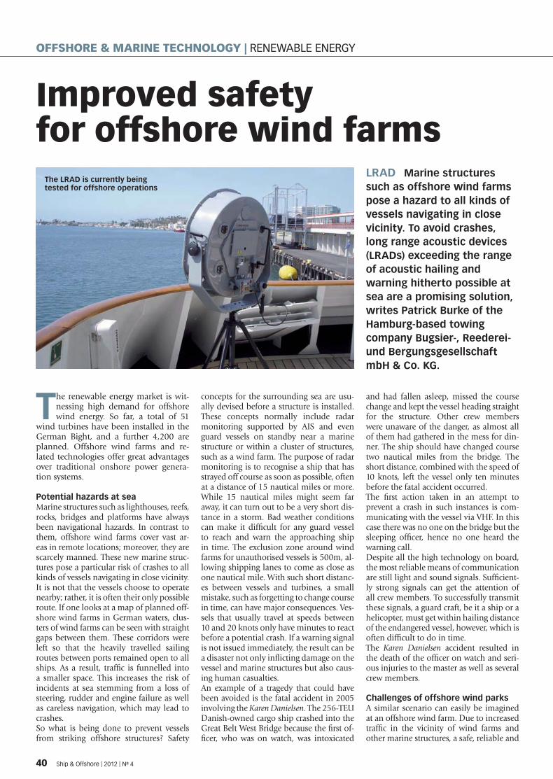
Improved safety for offshore wind farms
LRAD Marine structures such as offshore wind farms pose a hazard to all kinds of vessels navigating in close vicinity. To avoid crashes, long range acoustic devices (LRADs) exceeding the range of acoustic hailing and warning hitherto possible at sea are a promising solution, writes Patrick Burke of the Hamburg-based towing company Bugsier-, Reederei- und Bergungsgesellschaft mbH & Co. KG.
The renewable energy market is wit-nessing high demand for offshore wind energy. So far, a total of 51
wind turbines have been installed in the German Bight, and a further 4,200 are planned. Offshore wind farms and re-lated technologies offer great advantages over traditional onshore power genera-tion systems.
Potential hazards at seaMarine structures such as lighthouses, reefs, rocks, bridges and platforms have always been navigational hazards. In contrast to them, offshore wind farms cover vast ar-eas in remote locations; moreover, they are scarcely manned. These new marine struc-tures pose a particular risk of crashes to all kinds of vessels navigating in close vicinity. It is not that the vessels choose to operate nearby; rather, it is often their only possible route. If one looks at a map of planned off-shore wind farms in German waters, clus-ters of wind farms can be seen with straight gaps between them. These corridors were left so that the heavily travelled sailing routes between ports remained open to all ships. As a result, traffi c is funnelled into a smaller space. This increases the risk of incidents at sea stemming from a loss of steering, rudder and engine failure as well as careless navigation, which may lead to crashes.So what is being done to prevent vessels from striking offshore structures? Safety
concepts for the surrounding sea are usu-ally devised before a structure is installed. These concepts normally include radar monitoring supported by AIS and even guard vessels on standby near a marine structure or within a cluster of structures, such as a wind farm. The purpose of radar monitoring is to recognise a ship that has strayed off course as soon as possible, often at a distance of 15 nautical miles or more. While 15 nautical miles might seem far away, it can turn out to be a very short dis-tance in a storm. Bad weather conditions can make it diffi cult for any guard vessel to reach and warn the approaching ship in time. The exclusion zone around wind farms for unauthorised vessels is 500m, al-lowing shipping lanes to come as close as one nautical mile. With such short distanc-es between vessels and turbines, a small mistake, such as forgetting to change course in time, can have major consequences. Ves-sels that usually travel at speeds between 10 and 20 knots only have minutes to react before a potential crash. If a warning signal is not issued immediately, the result can be a disaster not only infl icting damage on the vessel and marine structures but also caus-ing human casualties. An example of a tragedy that could have been avoided is the fatal accident in 2005 involving the Karen Danielsen. The 256-TEU Danish-owned cargo ship crashed into the Great Belt West Bridge because the fi rst of-fi cer, who was on watch, was intoxicated
and had fallen asleep, missed the course change and kept the vessel heading straight for the structure. Other crew members were unaware of the danger, as almost all of them had gathered in the mess for din-ner. The ship should have changed course two nautical miles from the bridge. The short distance, combined with the speed of 10 knots, left the vessel only ten minutes before the fatal accident occurred. The fi rst action taken in an attempt to prevent a crash in such instances is com-municating with the vessel via VHF. In this case there was no one on the bridge but the sleeping offi cer, hence no one heard the warning call. Despite all the high technology on board, the most reliable means of communication are still light and sound signals. Suffi cient-ly strong signals can get the attention of all crew members. To successfully transmit these signals, a guard craft, be it a ship or a helicopter, must get within hailing distance of the endangered vessel, however, which is often diffi cult to do in time. The Karen Danielsen accident resulted in the death of the offi cer on watch and seri-ous injuries to the master as well as several crew members.
Challenges of offshore wind parksA similar scenario can easily be imagined at an offshore wind farm. Due to increased traffi c in the vicinity of wind farms and other marine structures, a safe, reliable and
The LRAD is currently being tested for offshore operations
40 Ship & Offshore | 2012 | No 4
OFFSHORE & MARINE TECHNOLOGY | RENEWABLE ENERGY
SPI_004-12_34_50_20120514145921_504941.indd 40 14.05.2012 14:59:52

economical way to protect them and pass-ing ships has to be developed. One of the envisaged measures is employ-ment of a helicopter that fl ies within hail-ing distance of the ship causing the threat. However, a helicopter is unreliable since it takes up to 45 minutes to reach some of the wind farms in the German Bight. Having the helicopter on standby near the wind farm would decrease the fl ight dis-tance, but – for mechanical as well as logis-tical reasons – reduce the availability, thus making it an inadequate solution. Keeping a guard vessel in the area of the wind farm is a better and more effi cient way of solving the problem. It would be able to remain at sea and within the wind farm 24/7, but the question is whether a single guard vessel could protect all sides of a wind farm. In the German Bight, wind farms can be up to ten nautical miles long. A guard vessel travelling at 20 knots would need approxi-mately 30 minutes to cross the farm. To ensure full safety, guard vessels would have to be stationed at every corner of the wind farm. This would increase traffi c, though, which would heighten the risk of accidents. Both options, helicopter and guard ves-sels, are costly and usually unappreciated
by wind farm operators. Wind farms and many other marine structures need spe-cialised vessels for the transfer of crew and supply of materials. The vessels could also be used for other duties such as guarding the structure. In case of a critical situation in which a ship heads towards the tur-bines, the specialised on-site vessels need to help evacuate personnel working there. The question is how close the guard vessel must get to the vessel causing the threat. What is the range of an acoustic hailing de-vice? How accurately can sound or light be aimed at a ship still a long way off? Had the Great Belt West Bridge been equipped with a long range hailing and beaming device, could the Karen Danielsen accident have been prevented?
Long range acoustic device communicationThe solution is to establish communica-tion with the threatening vessel as early as possible, either with light or sound. A long range communication device exceeding the distance of two nautical miles could be the answer to the problem. One of the most advanced communication devices on the market is the LRAD 2000x by the US-based LRAD Corporation. According
to the manufacturer, the device is capable of hailing with a 162dB source level at 1m, providing transmission of clear au-dio messages at ranges greater than 8km. Being able to communicate with a ship within this range, makes it possible for the guard vessel to be much more fl exible, enabling it to remain at a strategic point from which it can communicate through remote hailing. To improve the security of marine structures and wind farms, the tur-bines on the outskirts could be equipped with the LRAD 2000x. The device can be remotely controlled and thus aimed at a ship from an onshore radar monitoring centre. LRAD 2000x cannot be a replace-ment for a guard vessel but is the perfect complement in making the protection of offshore installations safer, simpler and more effi cient, reliable and economical.But the concept as well as the technology is still new. To date, the LRAD 2000x has been tested only for onshore purposes, where it achieved a range of 8km and be-yond. The device has yet to prove its off-shore capabilities. For offshore testing of the long range acoustic device, the LRAD Corporation is currently working with the Bugsier-, Reederei- und Bergungsgesells-chaft mbH & Co. KG.
SPI_004-12_34_50_20120514145921_504941.indd 41 14.05.2012 14:59:54
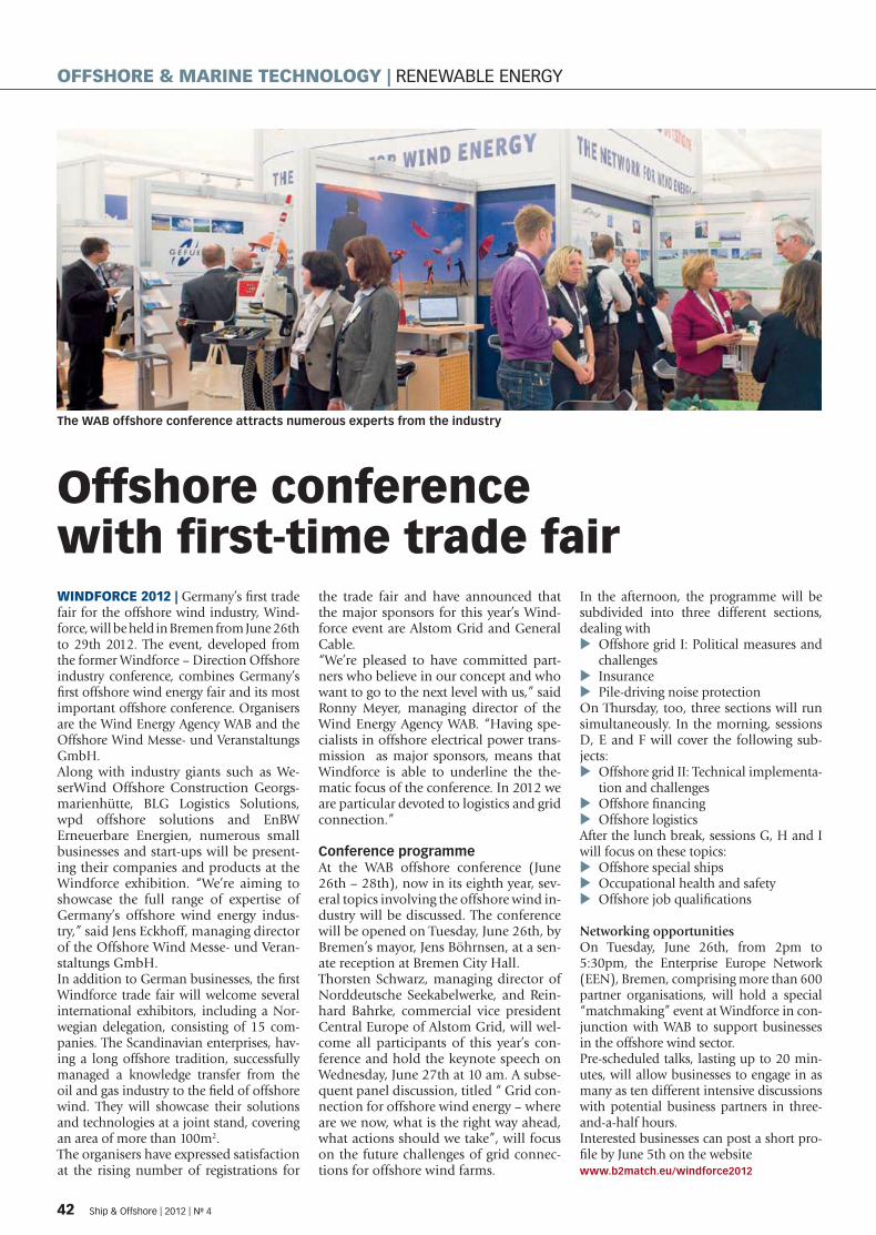
Offshore conference with fi rst-time trade fair WINDFORCE 2012 | Germany’s fi rst trade fair for the offshore wind industry, Wind-force, will be held in Bremen from June 26th to 29th 2012. The event, developed from the former Windforce – Direction Offshore industry conference, combines Germany’s fi rst offshore wind energy fair and its most important offshore conference. Organisers are the Wind Energy Agency WAB and the Offshore Wind Messe- und Veranstaltungs GmbH.Along with industry giants such as We-serWind Offshore Construction Georgs-marienhütte, BLG Logistics Solutions, wpd offshore solutions and EnBW Erneuerbare Energien, numerous small businesses and start-ups will be present-ing their companies and products at the Windforce exhibition. “We’re aiming to showcase the full range of expertise of Germany’s offshore wind energy indus-try,” said Jens Eckhoff, managing director of the Offshore Wind Messe- und Veran-staltungs GmbH.In addition to German businesses, the fi rst Windforce trade fair will welcome several international exhibitors, including a Nor-wegian delegation, consisting of 15 com-panies. The Scandinavian enterprises, hav-ing a long offshore tradition, successfully managed a knowledge transfer from the oil and gas industry to the fi eld of offshore wind. They will showcase their solutions and technologies at a joint stand, covering an area of more than 100m2. The organisers have expressed satisfaction at the rising number of registrations for
the trade fair and have announced that the major sponsors for this year’s Wind-force event are Alstom Grid and General Cable.“We’re pleased to have committed part-ners who believe in our concept and who want to go to the next level with us,” said Ronny Meyer, managing director of the Wind Energy Agency WAB. “Having spe-cialists in offshore electrical power trans-mission as major sponsors, means that Windforce is able to underline the the-matic focus of the conference. In 2012 we are particular devoted to logistics and grid connection.”
Conference programmeAt the WAB offshore conference (June 26th – 28th), now in its eighth year, sev-eral topics involving the offshore wind in-dustry will be discussed. The conference will be opened on Tuesday, June 26th, by Bremen’s mayor, Jens Böhrnsen, at a sen-ate reception at Bremen City Hall.Thorsten Schwarz, managing director of Norddeutsche Seekabelwerke, and Rein-hard Bahrke, commercial vice president Central Europe of Alstom Grid, will wel-come all participants of this year’s con-ference and hold the keynote speech on Wednesday, June 27th at 10 am. A subse-quent panel discussion, titled “ Grid con-nection for offshore wind energy – where are we now, what is the right way ahead, what actions should we take”, will focus on the future challenges of grid connec-tions for offshore wind farms.
In the afternoon, the programme will be subdivided into three different sections, dealing with
Offshore grid I: Political measures and �challengesInsurance �Pile-driving noise protection �
On Thursday, too, three sections will run simultaneously. In the morning, sessions D, E and F will cover the following sub-jects:
Offshore grid II: Technical implementa- �tion and challengesOffshore fi nancing �Offshore logistics �
After the lunch break, sessions G, H and I will focus on these topics:
Offshore special ships �Occupational health and safety �Offshore job qualifi cations �
Networking opportunitiesOn Tuesday, June 26th, from 2pm to 5:30pm, the Enterprise Europe Network (EEN), Bremen, comprising more than 600 partner organisations, will hold a special “matchmaking” event at Windforce in con-junction with WAB to support businesses in the offshore wind sector.Pre-scheduled talks, lasting up to 20 min-utes, will allow businesses to engage in as many as ten different intensive discussions with potential business partners in three-and-a-half hours.Interested businesses can post a short pro-fi le by June 5th on the websitewww.b2match.eu/windforce2012
The WAB offshore conference attracts numerous experts from the industry
42 Ship & Offshore | 2012 | No 4
OFFSHORE & MARINE TECHNOLOGY | RENEWABLE ENERGY
SPI_004-12_34_50_20120514145921_504941.indd 42 14.05.2012 14:59:54
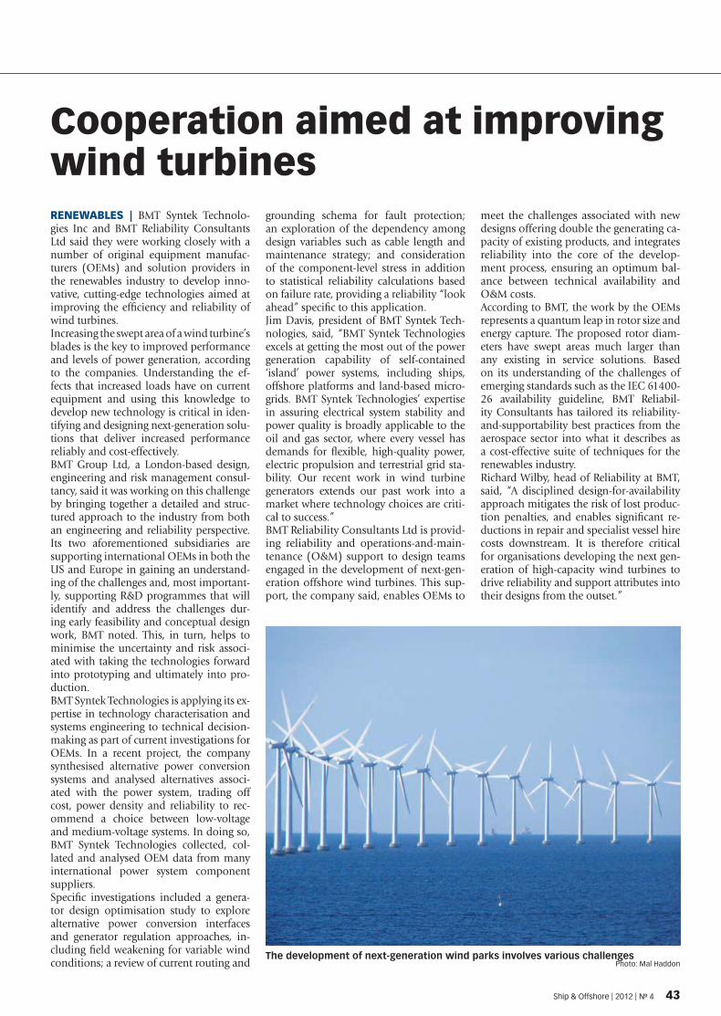
Cooperation aimed at improving wind turbinesRENEWABLES | BMT Syntek Technolo-gies Inc and BMT Reliability Consultants Ltd said they were working closely with a number of original equipment manufac-turers (OEMs) and solution providers in the renewables industry to develop inno-vative, cutting-edge technologies aimed at improving the effi ciency and reliability of wind turbines. Increasing the swept area of a wind turbine’s blades is the key to improved performance and levels of power generation, according to the companies. Understanding the ef-fects that increased loads have on current equipment and using this knowledge to develop new technology is critical in iden-tifying and designing next-generation solu-tions that deliver increased performance reliably and cost-effectively.BMT Group Ltd, a London-based design, engineering and risk management consul-tancy, said it was working on this challenge by bringing together a detailed and struc-tured approach to the industry from both an engineering and reliability perspective. Its two aforementioned subsidiaries are supporting international OEMs in both the US and Europe in gaining an understand-ing of the challenges and, most important-ly, supporting R&D programmes that will identify and address the challenges dur-ing early feasibility and conceptual design work, BMT noted. This, in turn, helps to minimise the uncertainty and risk associ-ated with taking the technologies forward into prototyping and ultimately into pro-duction.BMT Syntek Technologies is applying its ex-pertise in technology characterisation and systems engineering to technical decision-making as part of current investigations for OEMs. In a recent project, the company synthesised alternative power conversion systems and analysed alternatives associ-ated with the power system, trading off cost, power density and reliability to rec-ommend a choice between low-voltage and medium-voltage systems. In doing so, BMT Syntek Technologies collected, col-lated and analysed OEM data from many international power system component suppliers. Specifi c investigations included a genera-tor design optimisation study to explore alternative power conversion interfaces and generator regulation approaches, in-cluding fi eld weakening for variable wind conditions; a review of current routing and
grounding schema for fault protection; an exploration of the dependency among design variables such as cable length and maintenance strategy; and consideration of the component-level stress in addition to statistical reliability calculations based on failure rate, providing a reliability “look ahead” specifi c to this application.Jim Davis, president of BMT Syntek Tech-nologies, said, “BMT Syntek Technologies excels at getting the most out of the power generation capability of self-contained ‘island’ power systems, including ships, offshore platforms and land-based micro-grids. BMT Syntek Technologies’ expertise in assuring electrical system stability and power quality is broadly applicable to the oil and gas sector, where every vessel has demands for fl exible, high-quality power, electric propulsion and terrestrial grid sta-bility. Our recent work in wind turbine generators extends our past work into a market where technology choices are criti-cal to success.”BMT Reliability Consultants Ltd is provid-ing reliability and operations-and-main-tenance (O&M) support to design teams engaged in the development of next-gen-eration offshore wind turbines. This sup-port, the company said, enables OEMs to
meet the challenges associated with new designs offering double the generating ca-pacity of existing products, and integrates reliability into the core of the develop-ment process, ensuring an optimum bal-ance between technical availability and O&M costs.According to BMT, the work by the OEMs represents a quantum leap in rotor size and energy capture. The proposed rotor diam-eters have swept areas much larger than any existing in service solutions. Based on its understanding of the challenges of emerging standards such as the IEC 61400-26 availability guideline, BMT Reliabil-ity Consultants has tailored its reliability-and-supportability best practices from the aerospace sector into what it describes as a cost-effective suite of techniques for the renewables industry.Richard Wilby, head of Reliability at BMT, said, “A disciplined design-for-availability approach mitigates the risk of lost produc-tion penalties, and enables signifi cant re-ductions in repair and specialist vessel hire costs downstream. It is therefore critical for organisations developing the next gen-eration of high-capacity wind turbines to drive reliability and support attributes into their designs from the outset.”
The development of next-generation wind parks involves various challenges Photo: Mal Haddon
Ship & Offshore | 2012 | No 4 43
SPI_004-12_34_50_20120514145921_504941.indd 43 14.05.2012 14:59:5

Offshore frontiersDEEP WATER AND THE ARCTIC Oil and gas develop-ments are moving into a more and more challenging environment as “easy oil” discoveries decline, calling for new solutions and driving new technologies. The fron-tiers are in deep water, harsh environments and the Arctic, write Henrik Hannus and Per Kristian Bruun of Aker Solutions, Norway, reprising the presentation by Hannus at Ship&Offshore’s inaugural Business Offshore Conference in December 2011.
Deep-water oil and gas ex-ploration – from the Gulf of Mexico and offshore
Brazil to the North Sea – has some 20 years of history. A set of building blocks has evolved in terms of fl oating platform alternatives. Figure 1 shows the basic decision tree, starting with the take-off solution, then considering drilling/well inter-vention. The basic solutions are the FPSO (fl oating production, storage and offl oading), semi-submersible, TLP (tension leg platform) and SPAR. For fi nal selection, there are more subtle considerations such as delivery lead time, competitive situa-tion, client experience, etc.A typical modern-day plat-form is the Gjøa development off Norway, as illustrated in Figure 2, which shows the plat-form integration at the Stord yard. Ordinarily, the work is spread over different facilities before being brought together for integration. For deep wa-ter, the complications come in the mooring and riser systems. At water depths of more than 1,000m, the chain-wire-chain mooring is often replaced by chain-polyester rope-chain. The normal well connection
between seabed and fl oater is made with fl exible risers, but in deep water the riser weight and diameter are limiting. One solution is SCR (steel catenary risers), as used for the Blind Faith development in the Gulf of Mexico.The most common fl oating fa-cility is the ship-shape FPSO. For use in moderate environ-ments, the conversion of old tankers has been rather popu-lar.However, the requirements in harsh environments are very challenging because of the in-creased environmental loads and limited accessibility, and also because the high overall costs necessitate a large proc-ess and storage capacity, result-ing in a large topside. The lat-est harsh-environment FPSO currently operates in the Skarv fi eld, in the Norwegian Sea.When the reservoir requires sig-nifi cant well intervention, the dry tree and drilling concepts, TLPs and SPARs are favoured. However, the TLP has a limita-tion on the mooring system of about 1,500m. The SPAR has a cost step if the topsides ex-ceed the single lift capacity of the offshore crane vessels; i.e.
about 10,000 tonnes. For water depths of more than 1,500m and topsides larger than 10,000 tonnes, there is a gap in the concept portfolio. A new solu-tion under development is the dry tree semi-submersible. It is a modifi cation of the conven-
tional semi-submersible but with the wells on deck, con-nected to risers tensioned by long-stroke tensioners.The SPAR platform application has so far been limited to the Gulf of Mexico (and one in Ma-laysia). It has evolved from the
Figure 2: The Gjøa platform off Norway
Figure 1: Basic decision tree for fl oating structures
44 Ship & Offshore | 2012 | No 4
OFFSHORE & MARINE TECHNOLOGY | OIL & GAS
SPI_004-12_34_50_20120514145921_504941.indd 44 14.05.2012 14:59:5

classic SPAR to the truss SPAR and a special variant as the cell SPAR. When considering ap-plications for the harsh envi-ronment of the North Atlantic, special attention must be given to the long period seas and in-creased fatigue loading. A new concept for this application is the belly SPAR, as illustrated in Figure 3. The reduced diameter waterline increases the heave period, while the lower section is a plated cylinder so as to im-prove the fatigue redundancy over a truss structure. According to recent predic-tions for undiscovered oil re-serves, 25% can be found in arctic regions. Oil and gas de-velopment in the Arctic or in areas with arctic conditions is so far limited. Drilling cam-paigns were carried out in the Canadian Arctic in the 1980s using a fl oating moored buoy, spread moored drillships and gravity-based caisson struc-tures. Offshore production in the same areas has been per-formed using artifi cial islands and gravity-based structures. In the late 1990s, the fi rst fl oating moored production facilities were installed on the Grand Banks using turret moored FPSOs (no drifting sea ice, only icebergs), as the Sea Rose on the White Rose fi eld. The vessels are designed with a dis-connectable riser and mooring system so they can be discon-nected and moved off location in case of potential interaction with icebergs.In the Russian Arctic there have been a few offshore de-velopments. For the Sakha-lin II project, two gravity-based structures were installed east of the island of Sakhalin in the Russian Far East.For areas with drifting sea ice, drilling and developments have so far been limited to shallow waters using gravity-based structures since they can be designed to resist both the loads from drifting sea ice and impact with icebergs. As devel-opment in the Arctic moves to deeper water with drift ice and icebergs, there will be a need for a moored fl oating structure in both the drilling and pro-duction phase. At present there
is a gap in the existing technol-ogy. Development of oil and gas fi elds in these areas calls for new kinds of moored fl oating structures.A version of the SPAR platform adapted to the Arctic environ-ment has been developed. The Arctic SPAR differs from tradi-tional truss SPARs by having a downward breaking cone in the waterline to ensure that on-coming ice will fail in a fl exu-ral mode, thereby reducing the ice action (ice pressure – ice force) and the ice action effects (responses of the fl oating sys-tem). In the open water season, the SPAR is deballasted so the waterline is located at the verti-cal neck below the downward breaking cone. As there is limited agreement on how to analytically/nu-merically estimate the ice ac-tion and ice action effects on moored fl oating structures, ice model tests were performed at the Hamburg Ship Model Basin (HSVA). Tests were per-formed in several ice condi-tions, as shown in Figure 4. The objectives of the tests were to monitor the responses of the SPAR in various ice conditions for comparison with numerical pre-simulations, to calibrate the simulation models used and to improve understand-ing of how the broken ice will be transported vertically down and around the hull during the ice-structure interaction.Future Arctic drilling and pro-duction developments using moored fl oating structures call
for additional technical knowl-edge in order to increase safety and reduce environmental risk. To meet the new challenges, Aker Solutions proposes a step-wise approach in which the fi rst initiative is to learn more about moored fl oating structure be-haviour under real conditions in drift ice by installing a buoy structure in the Spitsbergen
area. The buoy will consist of a buoy structure, mooring system and monitoring equipment to perform continuous measure-ments of ice conditions and buoy responses simultaneous-ly. The objective of such a full-scale test is to provide a data set for comparison with existing simulation tools in order to calibrate and improve them.
Figure 4: Ice model tests at the Hamburg Ship Model Basin
Figure 3: The belly SPAR
Ship & Offshore | 2012 | No 4 45
SPI_004-12_34_50_20120514145921_504941.indd 45 14.05.2012 15:00:03

Need for investment in training and educationBRAZIL In 2011 Brazil became the world’s eleventh largest producer of oil. It is expected to become one of the top fi ve producers by 2020. In the following article, Ann-Charlotte Zervens, claims and contracts executive of Oslo-based Skuld Offshore, a specialist insurance provider to the offshore contracting industry, briefl y summarises the strict liability regime infl uencing hiring requirements for offshore professionals in the country.
With enactment of the Petroleum Law (Law No. 9,478/97)
in 1997, the Brazilian govern-ment broke the state monopoly on oil exploration and produc-tion exercised solely by Petro-bras, a semi-publicly owned company, since its founding in 1953. Since then, the number of international oil companies working in Brazil has grown rapidly, raising various labour issues.The law is also the reason that the number of foreigners en-tering Brazil for work or study exceeded the number of Brazil-ians leaving the country for the fi rst time in 20 years. Applica-tions for permanent work visas have increased by 68% since 2009, with Americans leading
the statistics, according to the Ministry of Justice. Brazil has strict restrictions on hiring foreign workers. In a company with more than three employees, at least two-thirds must be Brazilian nationals. In addition, the total amount of payable salaries must also ful-fi l the two-thirds requirement, which can pose a problem for international companies with well-paid foreign workers. This requirement is strictly mandated by law, and the government has proposed to expand it in certain areas by 2017, offshore pre-salt projects being one of them. The requirement to hire locals has posed a considerable prob-lem as the educational system for specialised workers cannot keep up with rapidly increas-
ing demand. Today the Brazil-ian Naval Academy is the main supplier of personnel to the oil industry, and due to high demand these inexperienced workers quickly become over-paid; unfortunately, the claims statistics follow the same pat-tern. Labour cost infl ation in Brazil is amongt the highest in Latin America. A lot of com-panies provide internships or in-house training to meet their own demands, but this is risky because under the law trainees cannot be contractually bound to hire on with the companies that trained them. The most sought-after employees are English-speaking engineers and managers, and an increase in work poaching has become a big issue.
In an attempt to overcome these issues, the government has introduced a new pro-gramme, called PROMINP (National Programme for the Mobilisation and Develop-ment of the Oil and Gas In-dustry), providing the industry with in-service training and certifi cation of professionals. However, the qualifi cations of many, who fi nish these cours-es, are still too low for the in-dustry. Most of the more ad-vanced trainees go directly to Petrobras, which currently em-ploys over 80,000 people and recently became the world’s tenth biggest corporation, ac-cording to the Forbes Global 2000 ranking of April 2012. As one of Brazil’s most prestig-ious companies, Petrobras so
Anyone who, through an illicit act (art. 186 and 187), causes damage to another is obliged to repair it.
Sole paragraph: The obliga-tion to repair the damage will exist, regardless of fault, in the cases specifi ed by Law or when the activity normally carried out by the party who caused the damage entails, by its nature, risk to the rights of others.
Case law rulings against the employer for strict liability have extended application of this liability regime even further – especially in the offshore industry, where any type of work can pose a high-er risk for the employee. Here strict liability has become the most common interpretation of the employer’s liability.
ARTICLE 927 �
The number of international oil companies working offshore Brazil has grown rapidly
46 Ship & Offshore | 2012 | No 4
OFFSHORE & MARINE TECHNOLOGY | HUMAN RESOURCES
SPI_004-12_34_50_20120514145921_504941.indd 4 14.05.2012 15:00:10
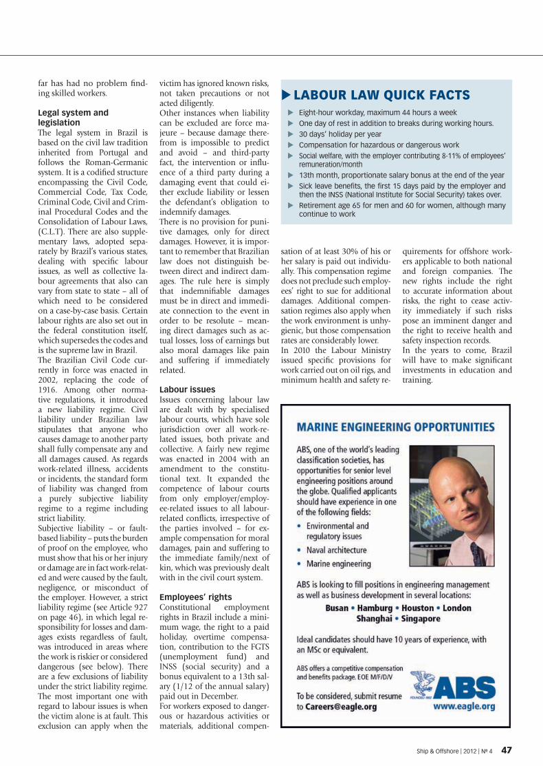
far has had no problem fi nd-ing skilled workers.
Legal system and legislationThe legal system in Brazil is based on the civil law tradition inherited from Portugal and follows the Roman-Germanic system. It is a codifi ed structure encompassing the Civil Code, Commercial Code, Tax Code, Criminal Code, Civil and Crim-inal Procedural Codes and the Consolidation of Labour Laws, (C.L.T). There are also supple-mentary laws, adopted sepa-rately by Brazil’s various states, dealing with specifi c labour issues, as well as collective la-bour agreements that also can vary from state to state – all of which need to be considered on a case-by-case basis. Certain labour rights are also set out in the federal constitution itself, which supersedes the codes and is the supreme law in Brazil.The Brazilian Civil Code cur-rently in force was enacted in 2002, replacing the code of 1916. Among other norma-tive regulations, it introduced a new liability regime. Civil liability under Brazilian law stipulates that anyone who causes damage to another party shall fully compensate any and all damages caused. As regards work-related illness, accidents or incidents, the standard form of liability was changed from a purely subjective liability regime to a regime including strict liability.Subjective liability – or fault-based liability – puts the burden of proof on the employee, who must show that his or her injury or damage are in fact work-relat-ed and were caused by the fault, negligence, or misconduct of the employer. However, a strict liability regime (see Article 927 on page 46), in which legal re-sponsibility for losses and dam-ages exists regardless of fault, was introduced in areas where the work is riskier or considered dangerous (see below). There are a few exclusions of liability under the strict liability regime. The most important one with regard to labour issues is when the victim alone is at fault. This exclusion can apply when the
victim has ignored known risks, not taken precautions or not acted diligently. Other instances when liability can be excluded are force ma-jeure – because damage there-from is impossible to predict and avoid – and third-party fact, the intervention or infl u-ence of a third party during a damaging event that could ei-ther exclude liability or lessen the defendant’s obligation to indemnify damages.There is no provision for puni-tive damages, only for direct damages. However, it is impor-tant to remember that Brazilian law does not distinguish be-tween direct and indirect dam-ages. The rule here is simply that indemnifi able damages must be in direct and immedi-ate connection to the event in order to be resolute – mean-ing direct damages such as ac-tual losses, loss of earnings but also moral damages like pain and suffering if immediately related.
Labour issuesIssues concerning labour law are dealt with by specialised labour courts, which have sole jurisdiction over all work-re-lated issues, both private and collective. A fairly new regime was enacted in 2004 with an amendment to the constitu-tional text. It expanded the competence of labour courts from only employer/employ-ee-related issues to all labour-related confl icts, irrespective of the parties involved – for ex-ample compensation for moral damages, pain and suffering to the immediate family/next of kin, which was previously dealt with in the civil court system.
Employees’ rightsConstitutional employment rights in Brazil include a mini-mum wage, the right to a paid holiday, overtime compensa-tion, contribution to the FGTS (unemployment fund) and INSS (social security) and a bonus equivalent to a 13th sal-ary (1/12 of the annual salary) paid out in December. For workers exposed to danger-ous or hazardous activities or materials, additional compen-
sation of at least 30% of his or her salary is paid out individu-ally. This compensation regime does not preclude such employ-ees’ right to sue for additional damages. Additional compen-sation regimes also apply when the work environment is unhy-gienic, but those compensation rates are considerably lower. In 2010 the Labour Ministry issued specifi c provisions for work carried out on oil rigs, and minimum health and safety re-
quirements for offshore work-ers applicable to both national and foreign companies. The new rights include the right to accurate information about risks, the right to cease activ-ity immediately if such risks pose an imminent danger and the right to receive health and safety inspection records.In the years to come, Brazil will have to make signifi cant investments in education and training.
Eight-hour work � day, maximum 44 hours a weekOne day of rest in addition to breaks during working hours. �30 days’ holiday per year �Compensation for hazardous or dangerous work �Social welfare, with the employer contributing 8-11% of employees’ �remuneration/month13th month, proportionate salary bonus at the end of the year �Sick leave benefi ts, the fi rst 15 days paid by the employer and �then the INSS (National Institute for Social Security) takes over.Retirement age 65 for men and 60 for women, although many �continue to work
LABOUR LAW QUICK FACTS �
Ship & Offshore | 2012 | No 4 47
SPI_004-12_34_50_20120514145921_504941.indd 4 14.05.2012 15:00:14

Rig type for increased oil recovery NORWAY | The international energy company Statoil has awarded Aker Solutions a con-tract to hire an entirely new type of rig, it describes as an impor-tant technological advance for the industry.The category B rig has been developed to increase recovery from existing fi elds.It is designed and equipped for the industrialisation of drilling and intervention services in ex-isting production wells and rep-resents a new sort of service. “This will be a very important part of the toolbox for in-creased recovery on the Norwe-gian continental shelf, making it possible to produce oil and gas that otherwise would be lost,” said Margareth Øvrum, Statoil’s executive vice presi-dent of Technology, Projects and Drilling. “The category B rig is the result of long-term, targeted technology develop-ment to increase subsea well recovery rates.” In cooperation with the supplier industry, Statoil has developed this new rig type and well-con-trol system, which is specially adapted to carry out well inter-vention and drilling operations in existing subsea wells.
It fi lls the gap between light in-tervention vessels (category A) and conventional rigs (category C). The category B rig, with associat-ed integrated services, is expected to reduce operating costs for well intervention by as much as 40%.
New technology Its design with integrated serv-ices is based on Aker Solutions’ own studies with a background in Statoil specifi cations. The rig type is designed for year-round well service in Statoil-operated activities.
It provides the option for a number of different types of well interventions using wireline and coiled tubing operations and is also designed to carry out side-track drilling from production tubing (through-tubing drilling – TTD) in a manner that allows simultaneous production from both the new sidetrack and exist-ing production tubing. The well services are conducted through existing subsea Christmas trees.“Statoil currently operates around 500 subsea wells, and we need effi cient tools to main-tain these. Collaboration be-tween many licences has been a precondition for establishing a long-term work programme,” said Ivar Aasheim, senior vice president of fi eld development at Statoil. Statoil and the licen-sees will enter into an eight-year contract with options for three times two years for the category B service. The estimated value of the contract is USD 1.9 bil-lion. In addition to rig rental, the contract includes rental of necessary equipment and serv-ices to carry out well interven-tion, sidetrack drilling, ROV operations, well testing and ce-menting. The rig will enter into service in 2015.The category B rig
Jack-up classifi cation Stern-fi rst navigationDNV | The classifi cation soci-ety Det Norske Veritas (DNV) has announced the launch of a dedicated rule book for self-el-evating units to help engineers and yards classing their designs and newbuilding projects. The rule book explains DNV and international regulations and standards. Adaptations from traditional offshore standards include additional class nota-tions and alignments of materi-al and jacking systems require-ments, based on feedback from industry experts and survey procedures. According to DNV,
the rule book for self-elevating units provides specifi c consid-erations, needed for jack-ups to prevent interpretations that could lead to imposing addi-tional requirements without any safety benefi ts. These con-siderations are especially rel-evant for jack-ups, taking into account their dual-fi xed and fl oating nature. Furthermore, the book introduces the new voluntary notation Enhanced Systems (ES). This notation covers industry’s needs to dem-onstrate safety and reliability beyond compliance.
LLOYD‘S REGISTER | The clas-sifi cation society Lloyd´s Register has issued new rules for stern-fi rst ice-class vessels in order to satisfy growing demand for technical support as the industry continues to explore the potential of polar transportation routes and new energy reserves in arctic regions. Lloyd’s Register said that the timely release of the rules came as more ships were being ordered with options such as podded propulsion systems and azimuth thrusters, allowing them to navi-gate stern fi rst in ice. According to the classifi cation society, develop-
ment of the rules was supported and validated by ice-class tanker designers, key regulators and operators. The interpretation of regulatory and other rule require-ments was confi rmed by a review of the current fl eet of double-act-ing ships, ensuring that practical experience supported the rules’ development. In addition to a framework for alternative-load scenarios when unusual opera-tions are envisaged, the guide-lines include interpretations of international regulations and classifi cation rules based on in-dustry precedents
48 Ship & Offshore | 2012 | No 4
OFFSHORE & MARINE TECHNOLOGY | INDUSTRY NEWS
SPI_004-12_34_50_20120514145921_504941.indd 4 14.05.2012 15:00:14
������������ �������������������������������������������������������� �����������
�����������, the ideal gateway to the maritime community, provides exclusive access to some of the key ��������� ��� ����������� �� �� ����������������������������������������������� �������� �����������
����������������������������������������������� ����������������� ������������������������marine technologies and equipment. Join the growing maritime community at ������������� !�!
������"��#�"��"����������#$�%��"
�!�&��'������(���� !����)�*���+����+��������,-��.��-/������0001����������012��32����
�"#$%& ���'()'�� ����������������������� �����*����������������For more information on how to secure your preferred location: 456�5'!7��558� �����2����9����12��1
:�2-���;�-�����<����+���2��������+�)=�+-���������������������� �� ������������������ ��������������+
>##?;#@�>##�%�#*=
ORGANISED AND MANAGED BY:SPONSORED BY:
CO-SPONSORED BY:
ENDORSED AND SUPPORTED BY:
Guangdong Economic and Information Commission The People’s Government of Guangzhou MunicipalityChinese Society of Naval Architects and Marine EngineersChina Association of the National Shipbuilding Industry
The Guangdong Society of NavalArchitects and Marine Engineers
Guangdong Association of Shipbuilding Industry Guangdong Maritime Safety Administration of P.R.C
Guangzhou Maritime Safety Administration of P.R.C
Guangzhou Port Authority China Classification Society, Guangzhou Branch
Fujian Association of ShipBuilding Industry
Guangdong Economic andInformation Commission
Holland Marine EquipmentPeople’s Government of Guangdong Province
The Society of Naval Architects &Marine Engineers, Singapore
The HongKong Joint Branch of the RoyalInstitution of Naval Architects and the
Institute of Marine Enggineers
The HongKong Institute of Marine TecTT hnology
The HongKong Institution of Engineer, MMNC Division
Marine Committee of China Electrotechical Society
Fujian Association of Ship Building Industry
The Norwegian Maritime ExportersChina State Shipbuilding Corporation
Ship & Offshore | 2012 | No 4 49
SPI_004-12_34_50_20120514145921_504941.indd 49 14.05.2012 15:00:15

Crane system deliveredOFFSHORE DRILLING | The largest crane system construct-ed to date by Germany-based J.D. Neuhaus (JDN) has been delivered to Westcon Loftete-knikk AS (WCL) of Norway for use on an offshore drilling rig. The semi-portal design com-prises an A-frame support-ing twin overhead horizontal track beams providing a 7.5m span.The crane has an approximate height of 11.5m with a total weight of 32 t. It is equipped with JDN hydraulic EH 40-H monorail hoists operating on each of the twin beams, each hoist providing an individual lift capacity of 40 t, JDN said. These hoists can be operated individually or simultaneously from one control, and when used in conjunction a total lift of 80 t is possible with a 12m-lift height available. A JDN Profi 6 TI-H hoist with 6 t lift
capacity is also provided to cov-er other operational or service requirements.The whole energy supply sys-tem, which was designed and manufactured by JDN, incor-porates four hydraulic drives provided for the crane travel movements. An electro-hy-draulic switch cabinet is also mounted on the access gang-way. The primary radio crane controls also have a back-up system fi tted to cover any radio control panel failure. Manual operation is also accommodat-ed to cover any unscheduled loss or failure of the electric power supply.The crane has been designed to comply with offshore op-eration, at temperatures down to -20ºC. Survival conditions can also be maintained in the event of inclines from the horizontal of the rig of 3º with the crane loaded or 27º when
unloaded. Operation in poten-tially hazardous environments is accommodated with an EX classifi cation of EX II 3 GD IIB T4. A special safety feature is incorporated with the crane to cover any disruption to or total loss of the main power supply. This feature comprises a back-up hydraulic pump with fl uid
reservoir tank to provide emer-gency lowering of suspended loads, together with safe posi-tioning of both hoist trolleys and crane.JDN added that the design, manufacture and performance of the crane complied with relevant standards and regula-tions.
Introduction of effi ciency-enhancing solutionsOIL AND GAS MARKET | At this year’s Offshore Tech-nology Conference (OTC) in Houston, Dresser-Rand, a glo-bal supplier of rotating equip-ment solutions to the oil, gas, petrochemical, power, and process industries, introduced product lines designed to both improve effi ciency and be customised according to client needs for the upstream, midstream and downstream onshore and offshore oil and gas markets.In addition to new magnetic bearings, Dresser-Rand has added to its product portfolio through its recent acquisition of Synchrony®, Inc, the DATUM® I Integrated Compression Sys-tem, a unit engineered with centrifugal separator technol-ogy to provide alternatives for
clients requiring a more com-pact solution to compression system design, while maintain-ing the DATUM line’s effi ciency standards.
Synchrony® magnetic bearings The use of magnetic bearings reduces environmental foot-print by eliminating ancil-lary equipment, including oil lubrication systems, and has been shown to help reduce energy consumption. By reduc-ing bearing losses, eliminating gearbox losses and improving aerodynamic effi ciency, Dress-er-Rand says, improvements in energy effi ciency greater than 10% can often be achieved in rotating machinery.By switching from oil-lubricated bearings to magnetic bearings,
clients could reduce their foot-print and weight in platform and FPSO applications that generate overall CAPEX savings in the construction phase, ac-cording to the company.
DATUM® ICS Building on its successful line of DATUM® compres-sors, Dresser-Rand recently developed a new compression concept – the DATUM® I in-tegrated compression system (ICS). Designed for onshore, off-shore, and subsea applications, the new system is engineered with centrifugal separator technology, incorporated on the compressor’s rotor to provide an effi cient, compact solution to compression sys-tem design. Maintaining the
reliability and effi ciency of the original DATUM compressor and reducing the size and cost, the DATUM ICS features cen-trifugal separation technology, a high-speed, close-coupled, gas-cooled motor, dedicated unit controls, process coolers, valves, instrumentation and interconnecting piping, ac-cording to Dresser-Rand. The DATUM ICS is said to pro-vide an effi cient and compact method of gas-liquid separa-tion that uses centrifugal force to separate oil, gas and water from the fl ow. The separation process protects the compres-sion fl ow-path from potential damage by removing free liq-uids, which can cause subse-quent fouling during the com-pression process, from the gas stream.
At the Westcon yard in Norway, the A-frame and track beams were assembled before the crane system was transported to its designated location on the rig
50 Ship & Offshore | 2012 | No 4
OFFSHORE & MARINE TECHNOLOGY | INDUSTRY NEWS
SPI_004-12_34_50_20120514145921_504941.indd 50 14.05.2012 15:00:1

Ship&Offshore
Buyer´s Guide
1 Shipyards
9 Navigation + communication
2 Propulsion plants
10 Ship´s operation systems
3 Engine components
11 Deck equipment
4 Corrosion protection
12 Construction + consulting
5 Ships´equipment
13 Cargo handling technology
6 Hydraulic + pneumatic
14 Alarm + security equipment
7 On-board power supplies
15
17
Port construction
Maritime services8 Measurement + control devices
16
18
Offshore + Ocean Technology
Buyer‘s Guide Information
The Buyer‘s Guide serves as market review and source of supply listing. ������������������ ����� ������������� ��������� ������ ��������� ���shipbuilding and supporting industry in the following columns.

II
1.06 Repairs + conversions
1 Shipyards
2.03 Couplings + brakes
2.01 Engines
2 Propulsion plants
1.10 Equipment for shipyards
2.02 Gears
2.05 Propellerswww.shipandoffshore.net
www.shipandoffshore.net
1.09 Offshore vessels
2.04 Shaft + shaft systemsHeise Schiffsreparatur & Industrie Service GmbHHoebelstrasse 55
D-27572 Bremerhaven
��������� �������������������� ������������
e-mail: [email protected]
Internet: www.heise-schiffsreparatur.de
Steel Construction, Pipe Works, Mechanical Engineering, Machining Technology, Berth: 220 m
Repairs and Conversions
Dockstraße 19���D-27572 BremerhavenTel. +49 (471)7997-10������ +49 (471)7997-18
����������������www.bredo.de
MWB Motorenwerke Bremerhaven AG Barkhausenstraße 60D 27568 Bremerhaven�������� ���!���"���������� ���!���"�
E-Mail: [email protected]: www.mwb.ag2 floating docks 167m x 24m, +PANMAX size,
1.000m pier facilities
www.stxosv.com
AVEVA Group plcHigh Cross, Madingley RdCambridge CB3 0HBEnglandTel: +44 1223 556655������#�#��$�%���www.aveva.com
Engineering design and information managementsolutions for the Plant and Marine industries
Cummins Deutschland GmbH
Peter-Traiser-Straße 1
64521 Gross-Gerau
GERMANY
Telefon:+49 6152 174-0
Telefax: +49 6152 174-141
Engine Hotline: +49 1520 9191000
www.cummins.de
Diesel engines for main and auxiliary drivesfrom 78 to 1.900 kW
Propulsion systems with power ratings from 250 up to 30,000 kW
REINTJES GmbHEugen-Reintjes-Str. 7D-31785 HamelinTel. +49 (0)5151 104-0 �������� !�!�����&��[email protected]���www.reintjes-gears.de
highly flexible, flexible and rigid couplings
REICH-KUPPLUNGENDipl.-Ing. Herwarth Reich GmbH'�����*;;<��=��!&���>�����F�$�*%Tel. +49 (0)234 959 16 0�������� �&�!��"��"e-mail: [email protected]
www.reich-kupplungen.de
Couplings, hydraulic components, brake systems
KTR Kupplungstechnik GmbHJ������>�%%���������>��&��J�����Tel. +49(0)59 71 798 0 ������� !�������"���%���O�%����P<��$�%�����www.ktr.com
Ortlinghaus, a leading specialist forplates, clutches, brakes and systems.
Ortlinghaus-Werke GmbHQ��P��*;���U<�����!���>����V��%��;P��$���Tel.: ����"����!��������O�����"����!�!
�������<���W��*;�$�%���www.ortlinghaus.com
Couplings, seawater resistent
R+W Antriebselemente GmbH X���������V��W����U<��=���D-63911 Klingenberg / Germany���O����� &����"4-0���O +49 (0)9372-9864-20email: [email protected]
Voith Turbo GmbH & Co. KGVoithstr. 174564 Crailsheim/GermanyTel. +49 (0)7951 32 - 0�������� �!��&��!��E-mail: [email protected]: www.voithturbo.com/industry
Fluid, Torque-limiting and Highly flexible couplings, Universal joint shafts and Hirth couplings
X�<�����Z[��;�V�W��D-22523 HamburgTel. +49 40 - 41 91 88 46������������������e-mail: [email protected]
�������������� ���� ����������������for drive shafts
Controllable-pitch propeller systems,Shaft lines
SCHOTTEL-Schiffsmaschinen GmbHSchottelweg 1 >��&���V�;%��Tel. �+49 (0) 3841 / 20 40���� +49 (0) 3841 / 20 43 33��%���O������;;\�;$��<<��������www.schottel.de
ANDRITZ HYDRO GmbH];$����V^;;�V�W��D-88212 RavensburgTel. +49(0)751 29511 0�������� �!���!���"�e-mail: [email protected]
Controllable Pitch Propellers
Controllable-pitch propeller systems,Shaft lines
SCHOTTEL-Schiffsmaschinen GmbHSchottelweg 1 >��&���V�;%��Tel. �+49 (0) 3841 / 20 40�����+49 (0) 3841 / 20 43 33��%���O������;;\�;$��<<��������www.schottel.de
Fixed and Controlable Pitch Propellers,Shaft Gears, Gearboxes
X%�X�<�����$���&���>��!&��_�`$P;<��<�������� �����"������������� ���&���"e-mail: [email protected]: www.piening-propeller.de

III
2.06 Rudders + rudder systems
2.12 Service + spare parts
2.07 Manoeuvring aids
2.10 Special propulsion units
2.11 Water jet propulsion units
3 Engine components
3.01 Heat exchangers
Your representative forDenmark, Finland, Norway and Sweden
ÖRN MARKETING AB ������������� ������������� ���
E-mail: [email protected]
Voith Schneider Propeller
Voith Turbo Schneider Propulsion GmbH & Co. KGPostfach 20 11D-89510 Heidenheim/GermanyTel.����&���&��"!!����������&���&�����!E-Mail: [email protected]/marine
V�����%�F��W����U<����!���>���!��_���������O��������������������O�������������"
e-mail: [email protected]
BARKE® Rudders and COMMANDER Steering Gears- High-Tech Manoeuvring Equipment -
Rudderpropellers, Transverse Thrusters, Pump-Jets
SCHOTTEL GmbHMainzer Str. 99D-56322 Spay/RheinTel. + 49 (0) 2628 / 6 10��������� ��"���|�"��&�����%���O������;$��<<����������www.schottel.de
2.09 Exhaust systems
PM, SOx and NOx reduction according to IMO regulations (MARPOL Annex VI)
Couple Systems GmbH Hamburger Landstr. 49D-21357 BardowickTel. +49 (0) 40 526000900��� +49 (0) 40 526000939e-mail: [email protected]
�� ����� �������� ��������������Diesel Particulate Filters / SCR Catalysts
Hug Engineering AG}%�_���������~���&!��]�;�*Phone +41 52 368 20 20������������!��&"�������������*W���W�$����www.hug-eng.ch
Complete SCR and Oxidation Catalyst-Systems
Johnson Matthey Catalysts (Germany) GmbHF������;<���&���"�!��J��\�<��|�_��%��^
�������!�����������������!������������%���O�;�����%�<<�� �̂$�%
www.jmcatalysts.com
Rudderpropellers, Twin-Propellers,Navigators, Combi-Drives, Pump-Jets
SCHOTTEL GmbHMainzer Str. 99D-56322 Spay/RheinTel. + 49 (0) 2628 / 6 10��������� ��"���|�"��&�����%���O������;$��<<����������www.schottel.de
Pump-Jets for main and auxiliary propulsion
SCHOTTEL GmbHMainzer Str. 99D-56322 Spay/RheinTel. + 49 (0) 2628 / 6 10��������� ��"���|�"��&�����%���O������;$��<<����������www.schottel.de
Hudong Heavy Machinerysee NIPPON Diesel ServiceHHM
KOBE DIESELsee NIPPON Diesel Service
MITSUBISHI DIESEL/TURBOCHARGERsee NIPPON Diesel Service
MOTOR-SERVICE SWEDEN ABZ[���������P;#�W��SE-610 72 VAGNHÄRADUV]>]����O��"��!"�&���������O��"��!"�����www.motor-service.se�� [email protected]
WORLDWIDE SPARE PART DELIVERIES
Auxiliary- / Emergency- /Containerized- Generating SetsExhaust Gas Silencers / Service / Spare Parts
Lindenberg-Anlagen GmbH�����*�W;<������U<��=������>�!����#���<�Tel.: +49 (0) 2204 48103-155���O����� ��������&��"[email protected]
spare parts for main and auxiliary engines
X�<�����Z[��;�V�W����>���!�&���%�*�WTel. +49 40 - 41 91 88 46������������������e-mail: [email protected]
Marine Engineering GmbH
Maintenance + repair of diesel engines, turbochargers, injection systems, on site and in harbour
����� ����������������������� ������������
Pol. Industrial de Guarnizo 18 39611 Guarnizo (Cantabria) / SpainTel. +34 942 558 600�����&���!!��&"�e-mail: [email protected]
www.mindasa.es
MWB Motorenwerke Bremerhaven AG Barkhausenstraße 60D 27568 Bremerhaven�������� ���!��������������� ���!���"�
E-Mail: [email protected]: www.mwb.ag
Development, modification and maintenance of engines
YANMAR DIESELsee NIPPON Diesel Service
TAIKO KIKAI INDUSTRIES CO.,LTDsee NIPPON Diesel Service
NIPPON Diesel ServiceHermann-Blohm-Strasse 1
D-20457 Hamburg
Tel. +49 (0)40 31 77 10-0
�������� ��&���!��
��%���O��������;�%������$�%���www.nds-marine.com
After Sales Service - Spare PartsDistribution - Technical Assistance
SCHIFFSDIESELTECHNIK KIEL GmbHKieler Str. 177D-24768 RendsburgTel. +49(0)4331 / 4471 0 �������� &&��|�������%���O�������;�<�P�������������www.sdt-kiel.de
Repairs - Maintenanceon-board service - after sales
Spare Parts for Marine, Mining, Industrial
SIWO GmbHSpare Parts Center�;<;<��;;���D-22844 NorderstedtTel. +49 (0)40 51 31 88-02 �������� ��!��&������[email protected]���www.siwo.eu
Shell & Tube Heat Exchanger, Air-Cooled Heat Exchanger, Pressure Vessel & Modular Structure
18 Tuas Avenue 18ASingapore 638868Tel: +65 68611433 ·����O���"!�"�"��&�[email protected] · www.heatec.com.sg
Maintenance and optimisation of plate heat exchangers, separators and fresh water generators
��*�<;<��=�������>�&�����F����$P��;<��<Tel. +49 (0)5062 899 25 0
���� +49 (0)5062 899 25 28��%���O�������;�;��#�$�������www.is-service.de
IV
3.13 Preheaters
3.12 Indicators
3.06 Turbochargers
3.05 Starters
3.07 Filters 3.09 Fuel treatment plants
4 Corrosion protection
4.02 Coatings
3.03 Pistons + cylinder liners
3.02 Guide + roller bearings
Special bronzes for plain bearings and sliding platesSelf lubricating plain bearings
PAN-METALLGESELLSCHAFT Baumgärtner GmbH & Co. KGAm Oberen Luisenpark 3D-68165 Mannheim / GermanyPhone: +49 (0)621 42303-0e-mail: [email protected]
since 1931
X�<�����Z[��;�V�W����>���!�&���%�*�WTel. +49 (0)40 570 30 33Fax +49 (0)40 570 30 32e-mail: [email protected]
Agent: DAROS Piston Rings
DÜSTERLOH Fluidtechnik GmbHAbteilung Pneumatik StarterIm Vogelsang 105>�!!�����<<��W����������&���������������������&���������]�%���O�������*�;<�����������www.duesterloh.de
Air Starters for Diesel andGas Engines up to 9.000 kW
ABB Turbochargingmore than 100 service stations world-wide
ABB Turbo Systems Ltd (head office)
F�*WW��;<��;;�������~��!���F����
���������!��!�!���������������!��!�!�!�
<*���$���W��W�$������$�%���www.abb.com/turbocharging
Service for ABB and BBC turbochargersOriginal ABB spare parts
FIL-TEC Rixen GmbH�;<��������"���>����&����%�*�WTel. +49 (0)40 656 00 61 +49 (0)40 656 856-0Fax +49 (0)40 656 57 31
���������<�$�������$�%���www.fil-tec-rixen.com
Filter spare parts and accessories, bilge waterelements, maintenance, repair and service.
Automatic, duplex and simplex filters for lubrication oil, fuel oil and sea water
BOLL & KIRCH Filterbau GmbHU��%��;;<����������>�!�����Q���������O������&�!"���������O������&�!"����&������������<����������www.bollfilter.de
Automatic, single and duplex filters for lubrica-ting oil, fuel, hydraulic and cooling water simplex, duplex and back-flushing filters + special systems for lubricating oil, fuel and heavy oil
MAHLE Industriefiltration GmbHSchleifbachweg 45 ��>��"�&������W������������"���������������"���&�E-mail: [email protected]: www.mahle-industrialfiltration.com
Fuel treatment systemsFilter/water separators
MAHLE Industriefiltration GmbH���������W�&��&&�����>�������%�*�WTel. +49 40 530040-0 Fax +49 40 530040-24193E-mail: [email protected]: www.mahle-industriefiltration.com
ELWA ELEKTRO WÄRME MÜNCHENA.HILPOLTSTEINER GMBH & CO. KGPostfach 0160 | D-82213 Maisachtel +49 (0)8141 22866-0 fax +49 (0)8141 22866-10email: [email protected] | www.elwa.com
Viscosity Control Systems EVM 3Standard Booster Modules
LEHMANN & MICHELS GmbH Sales & Service CenterU��%��;;<������>��!"��J�����W��Tel. +49 (0)4101 5880-0 Fax +49 (0)4101 5880-129e-mail: [email protected] www.lemag.de
Engine heaters for diesel engines and dual fuel electric driven propulsion systems
Hotstart GmbHAm Turm 8653721 Siegburg / GermanyTel. +49 (0) 2241 12734 10Fax +49 (0) 2241 12734 29e-mail: [email protected]
ELWA ELEKTRO WÄRME MÜNCHENA.HILPOLTSTEINER GMBH & CO. KGPostfach 0160 | D-82213 Maisachtel +49 (0)8141 22866-0 fax +49 (0)8141 22866-10email: [email protected] | www.elwa.com
Oil and Cooling Water Preheating
Steelpaint GmbH · Am Dreistock 9
D-97318 Kitzingen · Tel.: +49 (0) 9321/3704-0
Fax: +49 (0) 9321/[email protected] · www.steelpaint.com
1-component polyurethane corrosion protectionsystems for ports, sheet pilings, bridges,
shipbuilding, ballast tanks.
Your representative for Germany Austria and Switzerland
Friedemann StehrTel. +49 6621 9682930
E-mail: [email protected]
Oil Filtration & Water Separation Systems
C.C.JENSEN A/SLøvholmen 13 | DK-5700 Svendborg | DenmarkPhone: +45 6321 2014 | Fax: +45 6222 4615
[email protected] | www.cjc.dk
Clean Oil - Bright Ideas
Oil Filtration & Water Separation Systems
C.C.JENSEN A/SLøvholmen 13 | DK-5700 Svendborg | DenmarkPhone: +45 6321 2014 | Fax: +45 6222 4615
[email protected] | www.cjc.dk
Clean Oil - Bright Ideas
3.08 Separators
Maintenance and optimisation of plate heat exchangers, separators and fresh water generators
��*�<;<��=�������>�&�����F����$P��;<��<Tel. +49 (0)5062 899 25 0
Fax +49 (0)5062 899 25 28��%���O�������;�;��#�$�������www.is-service.de
Treatment plants for fuel and lube oil
GEA Westfalia Separator Group GmbH
Werner-Habig-Straße 1 · 59302 Oelde (Germany)Phone +49 2522 77-0 · Fax: +49 2522 77-1778Internet: www.westfalia-separator.com
Oil Filtration & Water Separation Systems
C.C.JENSEN A/SLøvholmen 13 | DK-5700 Svendborg | DenmarkPhone: +45 6321 2014 | Fax: +45 6222 4615
[email protected] | www.cjc.dk
Clean Oil - Bright Ideas

V
���������������� �������
5 Ships´equipment
4.05 Anodic protection
5.01 Sheet- + profile steel
5.06 Furniture + interior fittings
www.shipandoffshore.net
5.08 Supply equipment
4.03 Surface treatment
www.shipandoffshore.net
5.02 Insulating technology
5.07 Ship’s doors + windows WIWA Wilhelm Wagner GmbH & Co. KGGewerbestr. 1-3 D-35633 LahnauTel. +49 (0)6441 609-0 �������� "��"��!���%���O�������\�\�������www.wiwa.de
G.THEODOR FREESE GMBH & CO.KGCarl-Benz-Str. 29
D-28237 Bremen / Germany
Tel. +49(0)421 396 08-0
������� ���&"����!!�
��%���O�$��<�$<�W<������;�������www.gtf-freese.de
coatings, corrosion protection
TILSE Industrie- und Schiffstechnik GmbHSottorfallee 12D-22529 HamburgTel. +49 (0)40 432 08 08 0�������� ��&����������]�%���O�<��;��<��;��$�%�����www.tilse.com
Anti marine growth and corrosion systemMARELCO
Steel and FRP gratingIndustrial racking systems
SIN HIAP CHUANHARDWARE & ENGINEERING PTE LTDCo. Reg. No. 199801942M��*�;�V�;<�U<���<��U��W������"&��Tel. +65 6897 8860 ·���� +65 6897 [email protected] · www.singrating.com
G.THEODOR FREESE GMBH & CO.KGCarl-Benz-Str. 29
D-28237 Bremen / Germany
Tel. +49(0)421 396 08-0
������� ���&"����!!�
��%���O�$��<�$<�W<������;�������www.gtf-freese.de
insulating ship floors, A-60, A-30
FreudenbergFiltration Technologies KG
Tel.+49 (0)6201/80-6264 | �������� "���|���"��V������%�|�_��%��^[email protected]
Filters for intake air filtration of gas turbines,turbo chargers and HVAC systems
Axial fans & centrifugal fans www.pollrichdlk.com
����������� ���������������������������!����"� �#$%�����&'"()*� ���)'"()*�
Air conditioning and refrigeration
5.05 Galleys + stores
The world´s No. 1 supplier of marine foodserviceequipment, laundry systems and pantry appliances.
www.loipart.com
Lock and Hardware Concepts for Ship & Yachtbuilders
G. Schwepper Beschlag GmbH & Co.Velberter Straße 83D 42579 Heiligenhaus Tel. +49 2056 58-55-0���������!"�!��!!��e-mail: [email protected] www.schwepper.com
Ship, boat and yacht hardwareIn brass and stainless steel material
S&B Beschläge GmbHGießerei und MetallwarenfabrikIllingheimer Str. 10D-59846 Sundern��������� �&&������������ +49 (0)2393 [email protected]
Design & Function
Billstraße 217 · D-20539 HamburgTel: 0049-40-819 785 [email protected]
G.THEODOR FREESE GMBH & CO.KGCarl-Benz-Str. 29
D-28237 Bremen / Germany
Tel. +49(0)421 396 08-0
������� ���&"����!!�
��%���O�$��<�$<�W<������;�������www.gtf-freese.de
primary deck coverings, floor coverings
A-, B-, C- and H-class doors
Podszuck GmbHQ��*;�������V�W��"&�� 24148 Kiel ��Germany
Tel. +49 (0) 431 6 6111-0 ���������� �&��"�"������E-mail: [email protected] � www.podszuck.eu
Steel Doors - Fire Doors - Ship DoorsEstablished in 1919
®
TILSE Industrie- und Schiffstechnik GmbHSottorfallee 12D-22529 HamburgTel. +49 (0)40 432 08 08 0�������� ��&����������]�%���O�<��;��<��;��$�%�����www.tilse.com
FORMGLAS SPEZIAL Yacht glazingbent and plane, with installation
®
��<<�������Q��$�\�W������>�������U��#�<�����������!�!�"���������������!�!�"������%���O����;���;�<���%�����Internet: \\\�<���%�����
glare protectionsun protection and black-outs
DVZ-SERVICES GmbHBoschstrasse 9D-28857 SykeTel. +49(0)4242 16938-0������� ����"&��e-mail: [email protected]: www.dvz-group.deOily Water Seperators, Oil-in-Water - Monitors, Sewage Treatment
Plants, Ballast Water Treatment, R/O - Systems
Water treatment systems for theinternational maritime and oil&gas industry
ENWA Water Treatment ASF����!�����*;����""�U<�#��W���NorwayTel. +47 5163 4300������ +47 5163 [email protected]���www.enwa.com
Fresh water generation by MF/RO systems
Pall GmbH Marine Office Hamburg��%��\��P���W�����>��������%�*�W�������� ���!��������������� ���!����������;����P��<����*����������$�%���www.pall.com

VI
6.01 Pumps
6 Hydraulic+ pneumatic
5.15 Other marine equipment
5.11 Ballast water management
5.10 Oil separation
5.12 Yacht equipment
Your representative for Eastern EuropeWladyslaw JaszowskiPROMARE Sp. z o.o.Tel.: +48 58 6 64 98 47�������������� ��
E-mail: [email protected]
5.09 Waste disposal systems
5.14 ������� �!� Noise reducing systems
Your representative forDenmark, Finland, Norway and Sweden
ÖRN MARKETING AB ������������� ������������� ���
E-mail: [email protected]
ROCHEM UF-Systeme GmbH Seegelkenkehre 4 � D-21107 Hamburg
Tel. +49 (0)40 374 952 20 �������� ��&��!��!!
�������$��%������www.rochem.de
ROCHEM Membrane Systems for pure water generation by reverse osmosis
DVZ-SERVICES GmbHBoschstrasse 9D-28857 SykeTel. +49(0)4242 16938-0������� ����"&��e-mail: [email protected]: www.dvz-group.deOily Water Seperators, Oil-in-Water - Monitors, Sewage Treatment
Plants, Ballast Water Treatment
ROCHEM UF-Systeme GmbH Seegelkenkehre 4 � D-21107 Hamburg
Tel. +49 (0)40 374 952 20 �������� ��&��!��!!
�������$��%������www.rochem.de
ROCHEM Membrane Systems for purification of gray- and blackwater acc. IMO MEPC.159(55)
Ocean Clean GmbH�*%�Q`����*;�!D-18069 RostockTel.: +49(0)381 8112930���O����� &�������&��%���O�������$���$����������www.oceanclean.de
Membrane Supported Biological Sewage Treatment Plants
DECKMA HAMBURG GmbHKieler Straße 316, D-22525 HamburgTel: +49 (0)40 548876-0��������� ��!���"����eMail: [email protected] Internet: www.deckma.com
15ppm Bilge Alarm, Service + Calibration
DVZ-SERVICES GmbHBoschstrasse 9D-28857 SykeTel. +49(0)4242 16938-0������� ����"&��e-mail: [email protected]: www.dvz-group.deOily Water Seperators, Oil-in-Water - Monitors, Sewage Treatment
Plants, Ballast Water Treatment
MAHLE Industriefiltration GmbH���������W�&��&&�����>�������%�*�WTel. +49 40 530040-0 ��� +49 40 530040-24193E-mail: [email protected]: www.mahle-industriefiltration.com
Bilge water deoiling systems acc. MEPC.107(49), deoiler 2000 < 5 ppm & membrane deoiling systems of 1 ppm, oil monitors, oil treatment systems
Ocean Clean GmbH�*%�Q`����*;�!D-18069 RostockTel.: +49(0)381 8112930���O����� &�������&��%���O�������$���$����������www.oceanclean.de
Oily Water Separator
DVZ-BALLAST-SYSTEMS GmbHBoschstrasse 9D-28857 SykeTel. +49(0)4242 16938-0������� ����"&��e-mail: [email protected]: www.dvz-group.de
N.E.I. VOS Venturi Oxygen StrippingBallast Water Treatment
Ballast Water Treatment
BOLL & KIRCH Filterbau GmbHU��%��;;<����������>�!�����Q���������O������&�!"���������O������&�!"����&������������<����������www.bollfilter.de
MAHLE Industriefiltration GmbH���������W�&��&&�����>�������%�*�WTel. +49 40 530040-0 ��� +49 40 530040-24193E-mail: [email protected]: www.mahle-industriefiltration.com
Ballast water treatment (Ocean Protection System - OPS)
Ballast water treatment systems
GEA Westfalia Separator Group GmbH
Werner-Habig-Straße 1 · 59302 Oelde (Germany)Phone +49 2522 77-0 · Fax: +49 2522 77-1778Internet: www.westfalia-separator.com
3D Sonar SystemForward Looking Sonar System
Veinland GmbH Pappelallee 19>��!!�U��������U��������*;�������_��%��^Tel.: +49 33205 26 97-0���O���&&��!��"����e-mail: [email protected]
www.veinland.net
More than 25 years experiencein shock and vibration systems
Sebert Schwingungstechnik GmbHHans-Böckler-Str. 35D-73230 KirchheimTel. +49 (0)7021 50040�������� �����!����]�%����������;����<���W�����www.sebert.de
;*�;�������;����F��%��������$�����<�������;��J*%����
Excellent noise reducing technologyCalmmoon marine - self-adhesive - instant effect
SEKISUI CHEMICAL GmbHCantadorstraße 3>������>`;;������Tel. +49 (0)211 36977-0 �������� ����&"���&��[email protected] www.calmmoon.de
Noise Damping Sheet
� ��� �������������� ����� ������� ��� � ���� �pumps, boilers and E-motors
X�<�����Z[��;�V�W����>���!�&���%�*�WTel. +49 40 - 41 91 88 46������������������e-mail: [email protected]
Marine Engineering GmbH
Twin-Screw Pumps, Progressive CavityPumps, High Pressure Pumps
Bornemann GmbH}��*;<���;<��=������>�&�"�&������P��$����
Phone: ���� !���&���������O����� !���&��������������%����$�%���www.bornemann.com
#�����`����U<������D-28307 Bremen�����������"������������������"������e-mail: [email protected]: www.behrenspumpen.de
Ship Centrifugal Pumps

Water- and air-cooled compressors
VII
6.02 Compressors
6.05 Piping systems
www.shipandoffshore.net
"��#�����$��
6.03 Hydraulic systems
6.07 Remote controlled valve systems
! ����"����"�������#�$������"������
Körting Hannover AGBadenstedter Str. 56D-30453 HannoverTel. +49 511 2129-247 ��������!���������&Internet: www.koerting.deF`���U$������*O����������&����������O�����&�"�& e-mail: [email protected]
KRACHT GmbH_�\����;<��������>�!����V������
�������� �&��&!������������ �&��&!��������P��$�<��*���www.kracht.eu
Transfer pumps – Flow measurementMobile hydraulics – Industrial hydraulics
KRAL AGBildgasse 40, 6890 Lustenau, Austria
www.kral.at, e-mail: [email protected] Screw Pumps for Low Sulfur Fuels.
Magnetic Coupled Pumps.
TORNADO® Rotary Lobe Pumps and NEMO® Progressing Cavity Pumps as customized solutions
NETZSCH Mohnopumpen GmbHGeretsrieder Straße 1 ����V���P����*�W�|�_��%��^Tel. +49 (0)�"&��"&�������� +49 (0)8638 [email protected]���www.netzsch.com
BE > THINK > INNOVATE >
Grundfos A/SPoul Due Jensens Vej 7DK-8850 Bjerringbro, DenmarkTel: +45 87501400������O +45 [email protected] www.grundfos.com/marine
Neuenhauser Kompressorenbau GmbHHans-Voshaar-Str. 5D-49828 Neuenhaus
�������� !��"������������� !��"�����e-mail: [email protected]
www.neuenhauser.de � www.nk-air.comAir- and water-cooled compressors, air receivers
with valve head, bulk head penetrations
U<���<��;<���&�����>�&���!�>*���;<��<��������� !!�����!��������������� !!�����!"�
e-mail: [email protected]
Spare parts for water and air-cooled compressors
Filtration components and systems,Monitoring systems
Pall GmbH Marine Office Hamburg��%��\��P���W�����>��������%�*�W�������� ���!��������������� ���!����������;����P��<����*����������$�%���www.pall.com
Wafer Type Check Valves, Wafer Type Duo Check Valves, Special Valves
Ritterhuder Armaturen GmbH & Co. Armaturenwerk KGIndustriestr. 7-9 >��������;<�������U$���%��$P����������������������������������!��%���O�$��<�$<���<�W�$�%���www.ritag.com
Marine valves, indication,remote controls, ship spare parts
FAK-ARMATUREN GmbHLademannbogen 53D-22339 HamburgTel. +49 40 538949-0��������!&���E-mail: [email protected]: www.fak-armaturen.de
Quick Couplings & Multicouplers for shipbuilding, offshore & deepwater applications
WALTHER-PRÄZISION Carl Kurt Walther GmbH & Co. KG V�;<�����;<��=���42781 Haan, GermanyTel. +49(0)2129 567-0������ +49(0)2129 567-450e-mail: [email protected]
www.walther-praezision.de
MESON AB - THE VALVE SPECIALISTS OF SCANDINAVIA
Marine Engineering GmbH
MESON AB
X�<�����Z[��;�V�W��D-22523 HamburgTel. +49 40 - 41 91 88 46������������������e-mail: [email protected]
}��*;<���;<��=����>��!�!�V�����W;<��<��������� ����&��������������� ����&���������W������<��W�$�% ���www.goepfert-ag.com
% ����� �������������������������
aquatherm GmbHBiggen 5D-57439 Attendorn������������!�����������������!�����e-mail: [email protected]: www.aquatherm.de
fusiotherm® piping systems for shipbuilding- Approval by GL, RINA + BV
Heise Schiffsreparatur & Industrie Service GmbHHoebelstrasse 55
D-27572 Bremerhaven
��������� �������������������� ������������
e-mail: [email protected]
Internet: www.heise-schiffsreparatur.de
Steel Construction, Mechanical EngineeringPipe Works on ships, Repair + Newbuilding
Pipes and Fittings of CuNi10Fe1,6Mn
EUCARO BUNTMETALL GMBHU���<������%P���U<���&���>������F��%��Tel. �����!�����!��������������!�����!E-mail: [email protected]: www.eucaro.de
Straub Werke AGStraubstrasse 13~���&�&�V��W;�������������!����������������������!�����E-mail: [email protected]: www.straub.ch
STRAUB - With a Holistic View For The Right Connection
����������� ���������������������������!����"� �#$%�����&'"()*� ���)'"()*�
Piping systems: New building, conversion, repair.
����������������������&����' ��� ����������� �� ������ �HVAC, discharging and concealed cisterns for toilets.
Geberit International AG Q��������;<�������>���"����W������
Tel. +49 (0) 2173 285 310 ��� +49 (0) 2173 285 309
[email protected]�����www.geberit.com
F����;<`$P����������!���%�*�W��������� ���""�!&!������������� ���""�!&!��
info@goepfert-maritime-systems.comwww.goepfert-maritime-systems.com
Your specialist for automation, valve remote control and tank measurement

VIII
8.05 Flow measurement
8.06 Automation equipment
8.04 Level measurement systems
7.06 Cable + pipe transits
8 Measurement + control devices
8.02 Pressure monitoring
8.03 Temperature monitoring
www.shipandoffshore.net
7 On-board power supplies
7.01 Generating sets
7.04 Switch boards + control consoles
Emergency power plants, generators, transformers 5 - 2000 kVA, 400 V - 20 kV, 50/60 Hz
%����������#�%��& ���#��������
Jürgen Thiet GmbH _*<�����W;<���&������""&��}���\�J�����|�_��%��^��������������������������������
]�Z���O������<���<��������www.thiet.de
Auxiliary- / Emergency- /Containerized- Generating SetsExhaust Gas Silencers / Service / Spare Parts
Lindenberg-Anlagen GmbH�����*�W;<������U<��=������>�!����#���<�Tel.: +49 (0) 2204 48103-155���O����� ��������&��"[email protected]
Bridge Control Console, Engine Control ConsoleSwitchboard plant
INTERSCHALT maritime systems AG/�;����<<'�����D-22869 Schenefeldtel. +49 (0) 40 83033-0fax +49 (0) 40 8302617www.interschalt.de
GEAQUELLO® + FLAMMADUR®
Fire protection systems
AIK Flammadur Brandschutz GmbH�<<�������U<��;;��!D-34123 KasselPhone : +49(0)561-5801-0������ : +49(0)561-5801-240 e-mail : [email protected]
Druck- und DifferenzdruckmessumformerPressure and differential pressure transmitters
VEGA Grieshaber KGAm Hohenstein 113D-77761 Schiltach�������� ��&"�!������������� ��&"�!�������%���O����������#�W��$�%���www.vega.com
Exhaust Gas Thermometers, Temperature Sensors and Indicators
SIKA Dr. Siebert & Kühn GmbH & Co. KGStruthweg 7-9D-34260 Kaufungen�������!"�! ���&�����������!"�! ���&�!��%���O������;�P����<���www.sika.net
Sensors & Switches to controlPressure, Temperature, Level, Flow
Barksdale GmbHDorn-Assenheimer Strasse 27D-61203 ReichelsheimTel: +49 (0) 6035-949-0���O����� �"�&!�����e-mail: [email protected]
www.barksdale.de
TILSE Industrie- und Schiffstechnik GmbHSottorfallee 12D-22529 HamburgTel. +49 (0)40 432 08 08 0�������� ��&����������]�%���O�<��;��<��;��$�%�����www.tilse.com
pneumatic, electric und el.-pn. tank level gauging with online transmission
Füllstandssensoren für Flüssigkeiten & SchüttgutLevel sensors for all solids & liquids
VEGA Grieshaber KGAm Hohenstein 113D-77761 Schiltach�������� ��&"�!������������� ��&"�!�������%���O����������#�W��$�%���www.vega.com
%�'���� ������������ ����'�������������� ������������� � ��� ���*;%=�strictly according to makers specifications and your instructions.
X�<�����Z[��;�V�W��D-22523 HamburgTel. +49 40 - 41 91 88 46������������������e-mail: [email protected]
Official member of the Honeywell Enraf Tanksystem?��$����@��[ �\�� ��� ��������*;%��� ������$����
F����;<`$P����������!���%�*�W��������� ���""�!&!������������� ���""�!&!��
info@goepfert-maritime-systems.comwww.goepfert-maritime-systems.com
Your specialist for automation, valve remote control and tank measurement
KRAL AGBildgasse 40, 6890 Lustenau, Austria
www.kral.at, e-mail: [email protected] Consumption and Lube Oil
Measurement for Diesel Engines.
KRACHT GmbH_�\����;<��������>�!����V������
�������� �&��&!������������ �&��&!��������P��$�<��*���www.kracht.eu
Transfer pumps – Flow measurementMobile hydraulics – Industrial hydraulics
Fuel consumption measurement and monitoring systems.
Aquametro AGRingstrasse 75 · 4106 Therwil / SwitzerlandTel. +41 61 725 11 22 [email protected] · www.aquametro.com
Automation solutions for ships and offshore installations
Bachmannelectronic GmbHQ��*��$P��\�W�&&"��������P��$���X*;<���Tel. +43 / 55 22 / 34 97-0��� +43 / 55 22 / 34 97-102�������$�%�����������www.bachmann.info
F������;<�������>������J�;��W��<���Q��$P���������� ��!�"!�"������������� ��!�"!�"���!�������$P%��W%��������www.deckma-gmbh.de
Signal Light Columns, General-, Watch-, Hospitalalarm, Backup Engine Telegraph
Automation Systems, Voyage Data Recorder,Reefer Container Monitoring Systems, Ship Safety Systems
INTERSCHALT maritime systems AG/�;����<<'�����D-22869 Schenefeldtel. +49 (0) 40 83033-0fax +49 (0) 40 8302617www.interschalt.de
Oil Mist Detection and Propulsion Condition Monitoring for Diesel- and Gas Engines
MSS AGV�;;��<*�%;<��;;��&�>�""!����%�;��;�V������Tel. +49 (0)6331 14376-0�������� "&&���&�"����%���O������%;;����$�% www.mss-hx.com
IX
9.08 Telephone systems
9.11 Bridge equipment
10 Ship‘s operation systems
9.04 Navigation systems
9.02 Satellite + radio communication
8.09 Test kits
10.03 Loading + stability computer systems9 Navigation +
communication
9.09 Communication networks
Your representative forDenmark, Finland, Norway and Sweden
ÖRN MARKETING AB ������������� ������������� ���
E-mail: [email protected]
10.01 Fleet management systems
www.shipandoffshore.net
www.shipandoffshore.net
8.11 Tank level gauging systems
VISATRON Oil Mist Detection Systems against Engine Crankcase Explosions
Schaller Automation GmbH & Co. KG}��*;<������W�����>�""��F���;P�;<���
��������� "���!��������������� "���!����"���%���O������;$������������www.schaller.de
Test kits, autom. monitoring systems,sampling devices, ultrasonic cleaning
Martechnic GmbHAdlerhorst 4D-22459 HamburgTel. +49 (0)40 85 31 28-0�������� ���!�&������"E-mail: [email protected]: www.martechnic.com
F����;<`$P����������!���%�*�W��������� ���""�!&!������������� ���""�!&!��
info@goepfert-maritime-systems.comwww.goepfert-maritime-systems.com
Your specialist for automation, valve remote control and tank measurement
Connecting people and businesses at sea
Marlink���$�;���O��;��������������%�*�W�Brussels, Athens, Dubai, Mumbai,U��W���������P^���V�;���W<���>�~��������*;<��Tel.(24/7)O��&������&&����������O��&���&�&�&�&��$*;<�%���;��#�$��%�����P�$�%���www.marlink.com
Maritime Communication: a cost-efficient solution for communication over HF, satellite & GSM
networks incl. crew mail application
Swisscom Broadcast AGMaritime Communication�;<��%*���W��;<��;;���CH-3050 BernTel. +41 800 817 620 E-mail: [email protected] www.swisscom.ch/maritime
Manufacturers of Nautical Equipment
Am Lunedeich 131D-27572 BremerhavenTel.: +49 (0)471-483 999 0���O����� ����&����e-mail: [email protected]
Manufacturer of finest marine chronometers,clocks and electrical clock systems
Gerhard D. WEMPE KGDivision Chronometerwerke U<���;<��=���&���>����!���%�*�WTel.: + 49 (0)40 334 48-899���O������ ��&&���"�"E-mail: [email protected]
D-24100 Kiel, Tel +49(0)4 31-3019 - 0, Fax - 291
Email [email protected]
Neue A-TECHAdvanced Technology GmbHLitzowstr. 15D-22041 Hamburg�������� ��&�����"���������� ��&��"��e-mail: [email protected]
Communication Systems
Maritime Communication: a cost-efficient solution for communication over HF, satellite & GSM
networks incl. crew mail application
Swisscom Broadcast AGMaritime Communication�;<��%*���W��;<��;;���CH-3050 BernTel. +41 800 817 620 E-mail: [email protected] www.swisscom.ch/maritime
Marine seat systems for yachts and commercial ships
Pörtner GmbHV��<����U<������D-33619 BielefeldTel. +49 (0) 521 10 01 09 �������� �!����"���"�E-Mail: [email protected] internet: www.poertner-gmbh.de
Integrated Fleet/Ship Management SystemSafety and Quality Management Maintenance
CODie software products e.K.�;%���$�����$�%���www.codie-isman.com
ISM Software SystemPerformance Indicator Monitor
Veinland GmbH Pappelallee 19>��!!�U��������U��������*;�������_��%��^Tel.: +49 33205 26 97-0���O���&&��!��"����e-mail: [email protected]
www.veinland.net
Fleet Management Systems, Terminal Management Systems
INTERSCHALT maritime systems AG/�;����<<'�����D-22869 Schenefeldtel. +49 (0) 40 83033-0fax +49 (0) 40 8302617www.interschalt.de
C3-Obi – the onboard systemLocal Interface – Baplie/read and write
Müller+Blanck Software GmbHGutenbergring 3822848 Norderstedt / GermanyPhone : +49 (0) 40 500 171 0����O��������� ���!���������]�Z����O������Z��*;F������www.Capstan3.com
Capstan3 – the planners best friend
Loading ComputerCargo Handling Simulator
Veinland GmbH Pappelallee 19>��!!�U��������U��������*;�������_��%��^Tel.: +49 33205 26 97-0���O���&&��!��"����e-mail: [email protected]
www.veinland.net
Loading and Stability Computer Systems
INTERSCHALT maritime systems AG/�;����<<'�����D-22869 Schenefeldtel. +49 (0) 40 83033-0fax +49 (0) 40 8302617www.interschalt.de

X
12.02 Ship model basins
12.04 Research + development
12.01 Consulting engineers
12 Construction + consulting
11.06 Container cell guides
Your representative for Eastern EuropeWladyslaw JaszowskiPROMARE Sp. z o.o.Tel.: +48 58 6 64 98 47�������������� ��
E-mail: [email protected]
11.01 Cranes
11 Deck equipment
11.03 Lashing + securing equipment
12.03 Classification societies
www.shipandoffshore.net
Global Davit GmbH Graf-Zeppelin-Ring 2 D-27211 BassumTel. +49 (0)4241 93 35 0 �������� ���&�&!��!e-mail: [email protected]: www.global-davit.de
Survival- and Deck Equipment
d-i davit international gmbhSandstr. 20D-27232 Sulingen���������� ��&���������������� �&������e-mail: [email protected]: www.davit-international.de
Cranes, davits and free-fall systems
GERMAN LASHING Robert Böck GmbHZ��$*;���������>���&!�F��%��Tel. +49 (0)421 17 361-5���O +49 (0)421 17 361-99E-Mail: [email protected]: www.germanlashing.de
SEC Ship's Equipment Centre Bremen GmbHSpeicherhof 5 D-28217 BremenTel. ���� �&�"�������������� �&��!&��e-mail: [email protected]: www.sec-bremen.de
For container, RoRo and timber cargoLayout and optimization of lashing systems
SEC Ship's Equipment Centre Bremen GmbHSpeicherhof 5D-28217 BremenTel. ���� �&�"�������������� �&��!&��e-mail: [email protected]: www.sec-bremen.deLayout, 3D-design, delivery and installations
of container related constructions
Design – Construction – ConsultancyStability calculation – Project management
SDC SHIP DESIGN & CONSULT GMBHNaval Architectural Consultant and Calculation Services
www.shipdesign.dee-mail: [email protected]
Bramfelder Str. 164 - D-22305 HamburgT.:+49(40)6116209-0 -�����O��� "��"���9-18
Ship Design since 1981
Tel. +49 (0) 4921 9277 0 ����� +49 (0) 4921 9277 26
www.abh-emden.com
INGENIEUR-TECHNIK GMBH
Contract management, engineering and consultingservices for Marine and Offshore industries
Deltamarin Ltd.Purokatu 1�}�������JX}U}�����������O��&!����&&"�&��������O��&!����&���&����������<�%�����$�%���www.deltamarin.com
Your R&D partner for plant construction,maritime industry, offshore industryand steel construction
Brunel Transport & Energy, Rostockt. +49 381 857 63 05-0
www.brunel.de/brunel-transport-energy.php
Advice, concepts and concept/design reviewsfor offshore systems in ice and/or open waters
SEA2ICE LTD. & CO. KG��*���V�����������&!���%�*�W��_��%��^��
Tel. ������"�"&&�����*;<�����������"&�&��#�$��;����$��$�%���www.sea2ice.com
S.M.I.L.E.��$����F`���_%��V��P�������>����"����P������Tel. +49 (0)431 21080 10�������� &���������e-mail: [email protected]: www.smile-consult.de
Basic Design - Detailed DesignOutfitting - CAD/CAM - Technical Documentation
S.M.I.L.E. FEM GmbHV��P�������>����"����P������
Tel. +49 (0)431 21080 20
�������� &���������
e-mail: [email protected]
Internet: www.smile-fem.de
FEM - Coupling - OptimizationCFD - FSI - SHOCK - CRASH
THE HAMBURG SHIP MODEL BASIN
F��%�������U<����"����>���&�!���%�*�WTel. +49 (0) 40 69 20 30
�������� ���"����&�&!��%���O��������;#�������www.hsva.de
DNV Germany GmbH
Tel.: :
Classification and service beyond class
MANAGING RISK
(�������#�)������#������ �*���+���������#�,����' ����!���!������
F��%P�%�\�W����>����X%%��;��PTel. +49 (0)4102 23180
��������� �����&����E-mail: [email protected]
Internet: www.nordseetaucher.eu
NORDSEETAUCHER GmbHNORDSEETAUCHER GmbH
KBN Konstruktionbüro GmbHTheodor-Neutig-Str. 41D-28757 BremenTel. +49 421 66 09 6-0����������""���"���e-mail: [email protected]: www.kbn-cad.de
�����������#�-������������#�*������� ����
Dipl.-Ing. Wolfgang Schindler GmbHIngenieurbüro für SchiffbauZ`����\�W��"���>���&������\�<<Tel. (04608) 60 95-0������"�� �"��!�!�e-mail: [email protected]
FULL AHEAD! Marine Engineering GmbHBrauhausstieg 21D-22041 HamburgTel. +49 (0) 40 6003875-0��� +49 (0) 40 6003875-15e-mail: [email protected]
www.fullahead-engineering.com
14.06 Searchlights
XI
14 Alarm + safety equipment
14.01 Lifeboats + davits
13.03 Grabs
13 Cargo handling technology
14.02 Life jackets
14.04 Fire protection
14.09 Gas detection + alarmsystems
16 Offshore + OceanTechnology
16.07 Arctic + polar technology
16.08 Subsea technology
14.03 SOLAS Equipment
13.02 Cranes
13.01 Material handling equipment
www.shipandoffshore.net
Rope Grabs, Hydraulic Grabs, Motor Grabs with Electro Hydraulic Drive
MRS Greifer GmbH���\�W������>��������%;<��<Tel. +49 7263 91 29 0��������"&�������e-mail: [email protected]: www.mrs-greifer.de
Drahtseilwerk GmbHAuf der Bult 14-16D-27574 Bremerhaven Tel. +49 471 931 89 0 ���������&����&%��������<;���\��P������www.drahtseilwerk.de
Steel wire ropes up to 84 mm,special ropes for hoisting and luffing
Scheuerle Fahrzeugfabrik GmbH��;<��$�������>��"�����������$�����������"����������������"���������;$��*����������www.scheuerle.com
Global Davit GmbH Graf-Zeppelin-Ring 2 D-27211 BassumTel. +49 (0)4241 93 35 0 �������� ���&�&!��!e-mail: [email protected]: www.global-davit.de
Survival- and Deck Equipment
d-i davit international gmbhSandstr. 20D-27232 Sulingen���������� ��&���������������� �&������e-mail: [email protected]: www.davit-international.de
Cranes, davits and free-fall systems
Lifeboats, SPHL, Rescue Boats, Patrol Boats & Davit Systems
Vanguard Composite Engineering Pte Ltd tel. +65 6887 5034��� +65 6887 5043e-mail: [email protected] www.vanguardlifeboat.com
BETTER SOLUTIONS FOR SAFETY AT SEA
CM Hammar ABAugust Barks gata 15U]����&��'�;<�����[�*����������"�&�����"!�!���������"�&�������&�����$%��%%���$�%���www.cmhammar.com
Your One-Stop Solutions Provider for the Marine & Offshore Markets For Fire, Rescue & Safety Services
GLOBAL MARINE SAFETY (SINGAPORE) PTE LTDNo. 6, Gul Street 3, Singapore 629264Tel. +65 6897 7086��� +65 6897 8930E-mail: [email protected]��;�<�O�www.gms.com.sg
Liferafts, boats and special productsfor shipping and offshore industry
DSB Deutsche Schlauchboot GmbH & Co. KGX�W��\�W�!���>�&�"&��];$���;��*;��Tel. +49(0) 5534 301-0���� ��� �!!&�&������[email protected]
Neue A-TECH Advanced Technology GmbHLitzowstr. 15D-22041 Hamburg�������� ��&�����"���������� ��&��"��e-mail: [email protected]
.����*�����������������#�� ������������
F������;<�������>������J�;��W��<���Q��$P���������� ��!�"!�"������������� ��!�"!�"���!�������$P%��W%��������www.deckma-gmbh.de
Fire-, Smoke-, FWBLAFFS Systems,/��������������
Uffelnsweg 1020539 Hamburg
+49 (40)78 12 [email protected] � www.k-j.de
Fire Protection: KJ FireOff Systems, Sprinkler, CO2
��<<�������Q��$�\�W������>�������U��#�<�����������!�!�"���������������!�!�"������%���O����;���;�<���%�����Internet: \\\�<���%�����
UV- and whitelight searchlights
Handheld & Portable DevicesMonitoring with user identified locations
SIKA Dr. Siebert & Kühn GmbH & Co. KGStruthweg 7-9D-34260 Kaufungen�������!"�! ���&�����������!"�! ���&�!��%���O������;�P����<���www.sika.net
Advice, concepts and concept/design reviewsfor offshore systems in ice and/or open waters
SEA2ICE LTD. & CO. KG��*���V�����������&!���%�*�W��_��%��^�
Tel. ������"�"&&�����*;<�����������"&�& ��#�$��;����$��$�%���www.sea2ice.com
Diving- Salvage & Average ServiceHydraulic Engineering - Maritime Services
Baltic Taucherei- undBergungsbetrieb Rostock GmbHX�<���������U`��&���>����"�J�;<�$PTel.: +49 (0)381- 811 1000���O����� &������������E-mail: [email protected]
Price per entry per issue:
Size I H 30/B 58mm
Size II H 40/B 58mm
1 Keyword € 90,– € 120,–2 Keywords each € 85,– each € 115,–
3 Keywords each € 80,– each € 110,–
4 Keywords each € 75,– each € 105,–
5 Keywords each € 70,– each € 100,–
from 6 Keywords each € 65,– each € 95,–
Online: The premium online entry, including an active link, logo and e-mail, is free of charge for all customers of the Buyer’s Guide print issue.
Time span and discounts:Minimum time span for your booking is one year in one tar-get region! Each target region can be booked individually. For bookings in several regions, we offer the following rebate off the total price:Two target regions/year: 10%
Three target regions/year: 20%
The Buyer’s Guide provides a market overview and an index of supply sources. Every entry in the Buyer’s Guide includes your company logo (4 colour), address and communications data plus a concise description of product or services offered.
Europe International Select
Target
regions
Germany/ Central Europe Worldwide Vietnam, China,
Special GreenTech
Issues
January January –– – February/Vietnam
March – –– April –
May – May/China– June –
July – –– – August/Special GreenTech
September September –– – October/China
November November –– December –
1ShipyardsWerften
2Propulsion systemsAntriebsanlagen
3Engine componentsMotorenkomponenten
4Corrosion protectionKorrosionsschutz
5Ship's equipment
6Hydraulic & pneumatic equipmentHydraulik & Pneumatik
7On-board networksBordnetze
8Measurement & control devicesMess- und Regeltechnik
9Navigation & communicationsNavigation & Kommunikation
10Ship´s operation systems
Hệ thống điều khiển tàu
11Deck equipmentDecksausrüstung
12Construction & consultingKonstruktion & Consulting
13Cargo handling technologyUmschlagtechnik ?B;$�I;JI�$K�$$K�$L�
14Alarm and safety equipmentWarn- und Sicherheitsausrüstung
15Port constructionHafenbau
1617
Maritime servicesMaritime DienstleistungenDịch vụ hàng hải
You can advertise in these categories:
17.06 Professional Commercial Diver
17 MaritimeServices16.09 Marine equipment
+ components
17.05 Insurance
Your representative for Germany Austria and Switzerland
Friedemann StehrTel. +49 6621 9682930
E-mail: [email protected]
18 Buyer‘s Guide Information
XII
(�������#�)������#������ �*���+���������#�,����' ����!���!������
F��%P�%�\�W����>����X%%��;��PTel. +49 (0)4102 23180
��������� �����&����E-mail: [email protected]
Internet: www.nordseetaucher.eu
NORDSEETAUCHER GmbHNORDSEETAUCHER GmbH
Production of elements and mipulatorson offshore platforms and vessels
CEMET LTD SP. Z O.O.�QVWX?"Z/[V\Qtel. +48 58 301-41-68�"��%�])�����*<��'%&#���;)#<�)^� www.cemet.com.pl
ON LINE Safety Equipment "one stop" Shop
��$����}FJ]��U ��<���<�tel. +65 6266 1412��� +65 6266 1435
e-mail: [email protected]
Insurance Brokerfor seagoing- and inland shipping and fishery
�������;<���U<��=�����>�������U��#�<������<<���� Tel. +49 (0)4105 77028-0 (24 hour service)��� +49 (0)4105 77028-18�����~����J�������������www.Carl-Rehder.de
(�������#�)������#������ �*���+���������#�,����' ����!���!������
F��%P�%�\�W����>����X%%��;��PTel. +49 (0)4102 23180
��������� �����&����E-mail: [email protected]
Internet: www.nordseetaucher.eu
NORDSEETAUCHER GmbHNORDSEETAUCHER GmbH
Diving- Salvage & Average Service Hydraulic Engineering - Maritime Services
Baltic Taucherei- undBergungsbetrieb Rostock GmbHX�<���������U`��&���>����"�J�;<�$PTel.: +49 (0)381- 811 1000���O����� &������������E-mail: [email protected]
Hydrex provides fast on site repair solutions to underwater problems encountered by ships.
Hydrex NVHaven 292030 Antwerp / BelgiumTel. +32 3 213 53 00�����&��&���&�!&�����%���O��^������^������� www.hydrex.be
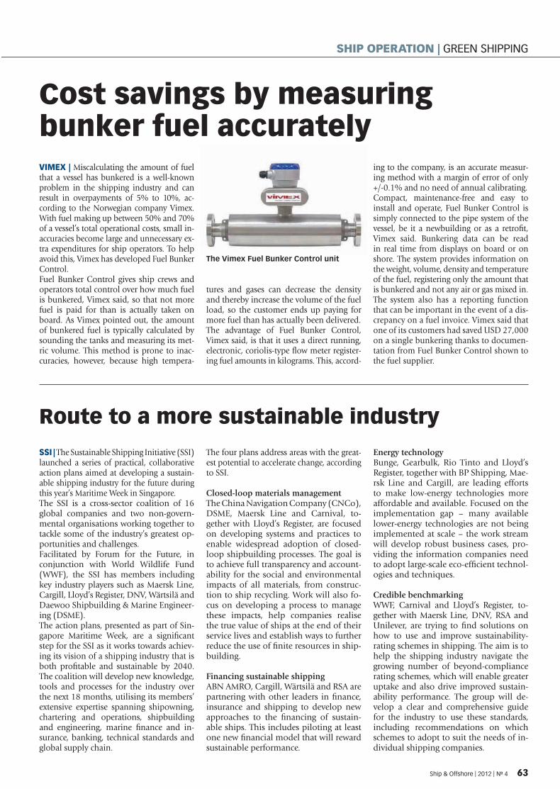
Cost savings by measuring bunker fuel accurately
Route to a more sustainable industry
VIMEX | Miscalculating the amount of fuel that a vessel has bunkered is a well-known problem in the shipping industry and can result in overpayments of 5% to 10%, ac-cording to the Norwegian company Vimex. With fuel making up between 50% and 70% of a vessel’s total operational costs, small in-accuracies become large and unnecessary ex-tra expenditures for ship operators. To help avoid this, Vimex has developed Fuel Bunker Control.Fuel Bunker Control gives ship crews and operators total control over how much fuel is bunkered, Vimex said, so that not more fuel is paid for than is actually taken on board. As Vimex pointed out, the amount of bunkered fuel is typically calculated by sounding the tanks and measuring its met-ric volume. This method is prone to inac-curacies, however, because high tempera-
tures and gases can decrease the density and thereby increase the volume of the fuel load, so the customer ends up paying for more fuel than has actually been delivered.The advantage of Fuel Bunker Control, Vimex said, is that it uses a direct running, electronic, coriolis-type fl ow meter register-ing fuel amounts in kilograms. This, accord-
ing to the company, is an accurate measur-ing method with a margin of error of only +/-0.1% and no need of annual calibrating.Compact, maintenance-free and easy to install and operate, Fuel Bunker Control is simply connected to the pipe system of the vessel, be it a newbuilding or as a retrofi t, Vimex said. Bunkering data can be read in real time from displays on board or on shore. The system provides information on the weight, volume, density and temperature of the fuel, registering only the amount that is bunkered and not any air or gas mixed in. The system also has a reporting function that can be important in the event of a dis-crepancy on a fuel invoice. Vimex said that one of its customers had saved USD 27,000 on a single bunkering thanks to documen-tation from Fuel Bunker Control shown to the fuel supplier.
SSI | The Sustainable Shipping Initiative (SSI) launched a series of practical, collaborative action plans aimed at developing a sustain-able shipping industry for the future during this year’s Maritime Week in Singapore.The SSI is a cross-sector coalition of 16 global companies and two non-govern-mental organisations working together to tackle some of the industry’s greatest op-portunities and challenges. Facilitated by Forum for the Future, in conjunction with World Wildlife Fund (WWF), the SSI has members including key industry players such as Maersk Line, Cargill, Lloyd’s Register, DNV, Wärtsilä and Daewoo Shipbuilding & Marine Engineer-ing (DSME).The action plans, presented as part of Sin-gapore Maritime Week, are a signifi cant step for the SSI as it works towards achiev-ing its vision of a shipping industry that is both profi table and sustainable by 2040. The coalition will develop new knowledge, tools and processes for the industry over the next 18 months, utilising its members’ extensive expertise spanning shipowning, chartering and operations, shipbuilding and engineering, marine fi nance and in-surance, banking, technical standards and global supply chain.
The four plans address areas with the great-est potential to accelerate change, according to SSI.
Closed-loop materials managementThe China Navigation Company (CNCo), DSME, Maersk Line and Carnival, to-gether with Lloyd’s Register, are focused on developing systems and practices to enable widespread adoption of closed-loop shipbuilding processes. The goal is to achieve full transparency and account-ability for the social and environmental impacts of all materials, from construc-tion to ship recycling. Work will also fo-cus on developing a process to manage these impacts, help companies realise the true value of ships at the end of their service lives and establish ways to further reduce the use of fi nite resources in ship-building.
Financing sustainable shippingABN AMRO, Cargill, Wärtsilä and RSA are partnering with other leaders in fi nance, insurance and shipping to develop new approaches to the fi nancing of sustain-able ships. This includes piloting at least one new fi nancial model that will reward sustainable performance.
Energy technologyBunge, Gearbulk, Rio Tinto and Lloyd’s Register, together with BP Shipping, Mae-rsk Line and Cargill, are leading efforts to make low-energy technologies more affordable and available. Focused on the implementation gap – many available lower-energy technologies are not being implemented at scale – the work stream will develop robust business cases, pro-viding the information companies need to adopt large-scale eco-effi cient technol-ogies and techniques.
Credible benchmarkingWWF, Carnival and Lloyd’s Register, to-gether with Maersk Line, DNV, RSA and Unilever, are trying to fi nd solutions on how to use and improve sustainability-rating schemes in shipping. The aim is to help the shipping industry navigate the growing number of beyond-compliance rating schemes, which will enable greater uptake and also drive improved sustain-ability performance. The group will de-velop a clear and comprehensive guide for the industry to use these standards, including recommendations on which schemes to adopt to suit the needs of in-dividual shipping companies.
The Vimex Fuel Bunker Control unit
Ship & Offshore | 2012 | No 4 63
SHIP OPERATION | GREEN SHIPPING
SPI_004-12_ 3_ _20120514132 04_50 25.indd 3 14.05.2012 13:31:41

Global C/Ku VSAT system introduced
INS type approval for bridge control system
CONNECTIVITY | To address commercial maritime busi-nesses’ growing need for af-fordable high-quality, end-to-end broadband connections, KVH Industries has introduced a “fi rst-of-a-kind” unifi ed dual-band maritime satellite com-munications solution that it says will reduce the complexity of bringing affordable offshore connectivity to vessels, almost anywhere they travel.The US-based company said the next-generation system of-fered a dual-band network with seamless switching between
C and Ku-bands for full glo-bal coverage serving all of the world’s major shipping routes, offshore oil fi elds, and com-mercial fi shing grounds, along with spread spectrum technol-ogy for faster speeds and wider coverage at a fraction of the price of competitive services.The new, one-metre Trac-Phone® V11 antenna is 85% smaller and lighter than most stand-alone C-band antennas, according to KVH Industries, which described the system as a hassle-free, fully integrated and unifi ed solution.
SYNAPSIS | Raytheon Anschütz has announced that its Synapsis Bridge Control, the new genera-tion of the German company’s bridge system, is the world’s fi rst navigation system that has been type approved under IMO’s new performance standards for inte-grated navigation systems (INS). The INS performance standards are specifi ed in the IMO resolu-tion MSC.252(83) and have ap-plied to all newbuildings with integrated navigation systems since January 1st 2011. Accord-ing to the standards, an INS is required to integrate the tasks of
collision avoidance, route moni-toring, route planning, naviga-tion control data display, status and data display and a central-ised human-machine interface for alert management on multi-functional displays. Raytheon Anschütz says that one key element of its Synapsis Bridge Control is a new multi-functional workstation that can replace stand-alone displays like ARPA radars, ECDIS or conning displays. Standardised hardware and software are said to allow customising bridge systems for any ship’s requirements.
Enhanced ECDIS launchedFURUNO | The marine elec-tronics manufacturer Furuno has announced the imminent launch of an ECDIS, in two models, that it said offered an enhanced user interface and functionality: the FMD-3200 (19” LCD) and FMD-3300 (23.1” LCD). Complying with the performance standard stipulated in IMO resolution MSC.232(82), the new ECDIS is suitable for both newbuilds and retrofi ts in fulfi lment of ECDIS mandatory carriage re-quirements to be phased in from July 2012 onwards, Fu-runo said. The new ECDIS, the com-pany added, will provide easy, streamlined chart management independent of chart providers. It is compatible with Jeppesen Dynamic Licensing and sup-ports the Admiralty Informa-tion Overlay (AIO). What is more, its network expandabil-ity fully satisfi es provisos for vessels’ paperless operation.As Furuno describes them, the FMD-3200 and FMD-3300 al-low the operator quick access to tasks to be performed dur-ing a vessel’s operation. The
new ECDIS has intelligently arranged graphic user interface elements: a status bar and in-stant access bar. The status bar, at the top of the screen, gives the operating status, includ-ing modes of operation and presentation. The instant ac-cess bar, on the left edge of the screen, provides quick access to functions available in each of the ECDIS operating modes. The contents of the instant ac-cess bar change according to
the operating modes selected on the status bar.The combination of status bar and instant access bar covers virtually all operational pro-cedures, eliminating the need to dig into an intricate menu tree, Furuno said. This stream-lines navigation monitoring procedure, reducing the risk of confusion and erroneous operation as well as enhancing situation awareness. The new ECDIS also employs a cutting-
edge chart-drawing engine that delivers instantaneous chart redraw with seamless zoom-ing and panning, thus making ECDIS operation stress-free, ac-cording to the manufacturer.Moreover, ECDIS operation is based on the same mouse scheme that people are used to with a PC, and all opera-tions can be controlled with a trackball in the control unit by means of left-clicking, right-clicking and use of a thumb-wheel. A full QWERTY-style keyboard is available in the ECDIS control unit for easy route, event and waypoint naming.By default, ECDIS functions as well as conning information display are available in the FMD-3200 and FMD-3300. In addition, both models can be extended to operate as radar/chart radar and alert manage-ment system, once activated. These functions can be in-stantly switched on by left-clicking the operating mode selector on the status bar. This expanded functionality pro-vides bridge operation fl ex-ibility, Furuno said.
The new ECDIS is said to offer enhanced functionality
64 Ship & Offshore | 2012 | No 4
SHIP OPERATION | NAVIGATION & COMMUNICATION
SPI_004-12_ 3_ _20120514132 04_50 25.indd 4 14.05.2012 13:31:41

Florian VisserAdvertising DirectorTel.: +49 – (0)40 / 237 14 –117Fax: +49 – (0)40 / 237 14 –236 E-Mail: fl [email protected]
If you are interested in placing your advertisement in one or more issues of SMM Daily News, please contact your local representative or our offi ce directly:
Concept & facts you should know:The SMM Daily News will appear every show day and will be distributed daily to visitors and exhibitors at the SMM. At breakfast time, the SMM-Daily will provide the latest news from the maritime industry to the international trade fair visitors in English language straight from the printers.
SMM Daily News Advertisement
Full colour rates+VAT
Bookable days are:Tuesday, September 4th 2012
Wednesday, September 5th 2012
Thursday, September 6th 2012
Friday, September 7th 2012
The 25th Shipbuilding, Machinery & Marine Technology International (SMM) trade fair will be staged at Hamburg Exhibition Centre from September 4th-7th 2012. Leading ship building companies and maritime equipment suppliers will present many innovations at this SMM.As usual, DVV Media will produce the daily trade fair newspaper SMM Daily News from Tuesday to Friday!
Here are the rates for your advertisement:
183 x 63 mm1/4-page
€ 1,390
183 x 251 mm1/1-page
€ 4,850
183 x 83 mm1/3-page
€ 1,790
183 x 125 mm1/2-page
€ 2,620
183 x 30 mm1/8-page
€ 850
I n a s s o c i a t i o n w i t h
No 1 | 7 September 2010
Recovery in shipbuilding
industry is now visible
A recovery in the shipbuilding
industry is now arriving follow-
ing two tough years, the Ger-
man government’s minister re-
sponsible for shipbuilding said
at the start of the SMM.
“The upturn has now arrived
in an initial form in some
shipyards,” said Hans-Joachim
Otto, State Secretary in Ger-
many’s federal Economics
Ministry and the German gov-
ernment’s coordinator for the
maritime industry. An increase
in world trade was expected
by the German government in
2011 which would in turn help
yards to recover, Otto told the
SMM opening press confer-
ence. “The recovery will come
in stages,” he said. “Firstly liner
shipping services followed by
ship owners involved in char-
tering will feel the benefi t.
German Economics Ministry State Secretary Hans-Joachim Otto (left), the German minister responsible for the shipbuilding industry, and
Bernard Meyer, chairman of the Community of European Shipyards’ Associations, at the SMM opening press conference Photo: HMC/Maack
GL – Y
our
competit
ive edge
www.gl-group.com/more-miles
Delivering more miles for your fleet
More miles through efficient ship management
} GL ShipManager
More miles between repairs through 3-D hull modelling
} GL HullManager
More miles per fuel-tonne through optimised trim
} ECO-Assistant
+ + + Visit us at Hall B4 GF, Stand 150 + + +
Liebherr-Werk Nenzing GmbH, a specialist for ship and mobile port cranes, is presenting its extensive range of heavy lift cranes at the SMM 2010. This includes the current Liebherr CBB Series with capacities of up to 450 tonnes.
The current Liebherr CBB se-ries of ship cranes are based on Liebherr’s proven design which has been progressed to include
technical features unique to Liebherr equipment. These cranes are also equipped with Liebherr’s own Litronic control system which not only increas-es efficiency but also provides for safer crane operation. Recent deliveries include two CBB heavy lift cranes for the vessel “Rolldock Sun” belong-ing to the Dutch heavy lift transport specialists Rolldock N.V. This ship is the first of a
number of sister vessels cur-rently on order. Each crane has a capacity of 350 tonnes at an outreach of 18 metres and 200 tonnes at an outreach of 33 metres.The cranes for the third heavy lift vessel in a larger series for the German shipowner Harren & Partner have just been deliv-ered. Each vessel is equipped with two CBB cranes with ca-pacities of 450 tonnes at 17 metres and 250 tonnes at 30 metres. The vessels “Palmer-ton” and “Palembang”, oper-ated by the Danish company K/S CombiLift, were delivered in 2009 and early 2010. Simultaneous operation of the CBB heavy lift cranes pro-vides capacities of up to 900 tonnes. They are controlled using the patented control sys-tem Sycratronic (simultaneous lifts) combined with the Dy-namic Anti Collision Control System (DACS) which ensures the highest possible perform-
ance and protection for the cranes. DACS prevents colli-sion between the crane booms and or fixed obstacles. When a number of cranes are operat-ing simultaneously, the action of each crane can be controlled based on information of the current position of the neigh-bouring cranes. The unique feature of DACS is that the sys-tem automatically calculates actual position, speed and the acceleration of each crane as well as the load moment limi-tation. This provides the crane driver with maximum flex-ibility backed with full safety. Conventional anti-collision systems define a virtual border in order to prevent the cranes from colliding. However, this results in a restriction of the working radius of each crane. With DACS the working radii are not restricted.
Liebherr at the SMM 2010: Hall A1 / Stand 352
Liebherr presents 450 tonne heavy lift cranes
M/S “Palmerton” is fitted with two CBB cranes from Liebherr Photo: Liebherr
REPAIR, CONVERSION & MAINTENANCEVisit us
in Hall B4.EG,
Booth 461
ABB Turbocharging.
Setting a new
standard.ABB Turbocharging introduces the all-new
A100 turbocharger generation as a significant
step in the development of single-stage, high-
efficiency, high-pressure turbocharging.
www.abb.com/turbocharging
14 SMM Daily News | 7 September 2010 | No 1
SMM DAILY NEWS | CRANES
Liebherr at the SMM 20110: Halll A1 / Stand 352
ts 450craness
Vissit us
inn Hall B4.E
BBooth 461
www.abb.com/turbocharging
JUST FOR FUN: �Illuminated water concertIn the centre of Hamburg next to the SMM fairground is the city’s famous and beauti-ful park Planten un Blomen. Here you will find a large bo-tanical garden with a tropical hothouse and Europe’s largest Japanese garden: A quiet but impressive attraction after a hectic day at the trade fair. In the summer, the illuminated water concert every evening on the park’s lake is an especially-loved attraction. As darkness falls, local people and tourists take a seat around the lake and admire the fountains of water which are shot into the evening air in illuminated timing with the music. During the SMM, Bolero from Ravel is on the programme. The show begins every evening at 21 hours and entry is free. www.plantenunblomen.hamburg.de
WINE AND DINE: �Restaurant VletPerhaps there is nowhere else in Hamburg where you get the impression that time has stood still than in the historic Speicherstadt. This is an area with tall former warehouses built in red brickwork sited be-tween canals, small alleyways and many bridges. But be-hind the historic brick build-ings there is a pulsating life-style, with some of the most fascinating aspects of the city. For over 100 years this area was a freeport, storing valu-able goods such as coffee, tea, spices and tobacco behind its imposing brick walls. Today,
in a restored warehouse build-ing yo will find the Restau-rant Vlet. The restaurant con-vinces with its combination of a modern and historic at-mosphere plus modern north German cuisine. The famous Gault Millau restaurant guide heaped praise on the restau-rant and gave it 14 points in its latest edition.
Restaurant Vlet Am Sandtorkai 23/24 Hamburg Tel +49-(0)40-33475375-0 www.vlet.de
What’s upPlanten un Blomen Park Photo: www.mediaserver.hamburg.de
Restaurant Vlet
There is nothing like SMM…...with SMM Daily News
� Visit us at A1.534 and book your advertisement!
With a daily circulation of 10,000 copies the newspaper is distributed to exhibitors and visitors at the fair and to affi liated hotels “hot off the press”.
Why not try out this last minute opportunity to reach more than 53,000 visitors and 1,900 exhibitors.
Visit us! Stand A1.534
30 SMM Daily News | 7 September 2010 | No 1
SMM DAILY NEWS | WHAT´S UP IN HAMBURG
JUST FORR FUN�
wwww.plantenunblomenn.hamburg.d
WINE AND DINE:
Restaurant VletAm Sandtorkai 23/244HamburgTel +49-(0)40-334753775-0 www.vlet.de
What’s up
ThereSMM Daily Ne
� Visit us at A1.534 aand book your advertisement!
Visit usus! Stand AA1.534
M DAILY NEWS |
I n a s s o c i a t i o n w i t h
YOUR logo
FOR YOUR INFO: �HafenCityAn impressive example of Hamburg’s dynamism is the HafenCity. This is currently Europe’s largest inner city development project which will create a new milestone in the city’s history. An en-tirely new city district on a space of 157 hectares is be-ing built next to the histor-ic Speicherstadt area. In a fascinating mix of historic buildings and modern archi-tecture, homes for 12,000 people and a business area for 40,000 jobs are being cre-ated. The pulsating HafenC-ity with its many attractions
is a magnet for the people of Hamburg and tourists to wonder around and enjoy. The highlights include the massive Elbphilharmonie which is a concert hall with revolutionary architecture now being built on the site of a former port warehouse, the Margellan and Marco Polo terraces and the cruise ship terminal where during the SMM the two German cruise vessels Astor and Deutsch-land will be moored.
www.hafencity.com
Magellan-Terrassen at Hamburg’s HafenCity
Photo: www.mediaserver.hamburg.de
Booking Centre for maritime business & professional events
Hamburg Messe und Con-gress (HMC) has set up a specialist centre at the SMM 2010 which offers information about the wide range of maritime and professional events organised by the HMC.
All those interested can also make their bookings for the events and trade fairs. The counter is at the central entrance, upper fl oor, between Halls A1 und A4.
SMM Istanbul 26-28 January 2011www.smm-istanbul.com
SMM India, Mumbai7-9 April 2011www.smm-india.com
MS&D, HamburgInternational Conference and Exhibition on Mari-time Security and Defence15-17 June 2011www.msd-hamburg.com
Seatrade Europe, HamburgCruise and Rivercruise Convention27-29 September 2011www.seatrade-europe.com
SMM Hamburg4-7- September 2012www.smm-hamburg.com
Book tip of the day: The German Merchant Fleet 2010/2011A completely revised edi-tion has been published of a reference work with a long tradition, “The Ger-man Merchant Fleet – Die Deutsche Handelsflotte 2010l11”. No other work offers such comprehensive facts about the entire German merchant fleet. The 53rd edition contains updated data and facts about some 4,000 ships and approxi-
mately 1,650 detailed ship illustrations plus the con-tact addresses of the ship owners.
Together with this edition the reader obtains access to an online database. In this database the com-plete editorial content of the book plus photographs of the ships can be found. “The German Merchant Fleet – Die Deutsche Han-delsflotte” is an indis-pensable working aid for all those whose work in-volves merchant shipping.
THE MARITIME BOOKSTORE RECOMMENDS
Author: Jan MordhorstPublisher: DVV Media GroupISBN: 978-3-87743-421-5
Subscription price up to 15 September 2010: 380 Euro (incl. VAT., excl. shipping costs)Price from 16 September 2010: 480 Euro (incl. VAT., excl. shipping costs)
SMM DAILY NEWS | WHAT´S UP IN HAMBURG
Just drop off your business card at stand A1.534.Daily draw prize – one Seehafen Verlag bookWeekly draw prize – one iPad
Win an iPad! Enter our lucky draw!
SMM Daily News | 7 September 2010 | No 1 31
FORR YOUR INFOO: ��
www.hafencity.com
Bomapro
ww
ww
ww
ww
ww
BBook tip of the day:
THE MARITIMEBOOKSTTORE RECOMMENDS
SMM DAAILY NEWS |
WWin an iPadd! Enter our lucky draw!
Germany’s Nobiskrug Werft, based in Rendsburg, is currently carrying out a re-fit of the German navy Class 123 frigate “Mecklenburg-Vorpommern” it its dock in Kiel. Along with the usual overhaul work on the ship superstructure and pro-pulsion system, a wide range of technical alterations are involved. These include the refitting of the cooling system with
an environmentally-friendly coolant, the rebuilding of the fire-fighting system and expansion of the on-board communica-tions systems. The Nobiskrug yard has in past years made a name for itself in construction of luxury motorised me-gayachts from a length of 60 metres. But repairs remain an important business sector: Nobiskrug offers rebuilding, re-
pairs, refits, lengthening, installation of new engines and restoring of all types of ships, especially naval vessels and yachts. The yard can also undertake a wide range of worldwide ad hoc repair work thanks to a flexible mobile task force.
Nobiskrug-Werft at the SMM 2010: Hall B4.EG / Stand 230
The “Mecklenburg-Vorpommern“ in the Nobiskrug yard’s Kiel dock Photo: Nobiskrug
Nobiskrug makes frigate fit
environ
mentally-friendly
be
cker productsinnovation
press
conferen
ce
SMM Daily News | 7 September 2010 | No 1 15
SMM DAILY NEWS | SHIPREPAIR
NNobiskrug
SSMM DAILY NEWS |
SPI_004-12_ 3_ _20120514132 04_50 25.indd 5 14.05.2012 13:31:45

Call for EU tonnage tax stabilityMOORE STEPHENS | International ac-countant and shipping adviser Moore Stephens, whose headquarters are in Lon-don, has urged stability for European ton-nage tax regimes now that the European Commission (EC) has begun its review of the European Union’s Guidelines on State Aid to Maritime Transport.The start of the EC’s review of the EU guide-lines was announced in mid-February. The guidelines cover European tonnage tax re-gimes as well as other state aid to the mari-time sector. The EC, the EU’s executive arm, has published a detailed and very compre-hensive questionnaire regarding these state aid guidelines, inviting responses from citi-zens, organisations and public authorities. The EC says the objective of the consul-tation is to invite member states, other
institutions and stakeholders to provide information on industry developments, feedback on the application of the 2004 Community Guidelines on State Aid to Maritime Transport (due for review within seven years of their date of appli-cation) and their effects, as well as any comments and proposals regarding state aid for maritime transport. The EC will analyse the outcome of the consultation before deciding to what extent changes to the current rules are necessary and, if ap-propriate, come forward with a proposal for revised guidelines. At this stage, the EC has not taken a position concerning a possible modifi cation of the existing guidelines.Moore Stephens tax partner Sue Bill said, “We hope the EC will bear in mind the im-
portance of stability to European tonnage tax regimes. This is particularly impor-tant given the current diffi cult economic climate, and the fact that EU tonnage tax regimes are competing with other jurisdic-tions, such as Singapore, which offer very attractive tax breaks to the shipping sector. It will be important for all interested par-ties in the EU to ensure that they are in-volved as much as possible in the consulta-tion process.”In a separate development, shipowners in the UK tonnage tax regime were recently encouraged by positive remarks made at the UK Chamber of Shipping’s recent an-nual dinner by Shipping Minister Mike Penning, who said the UK government had no intention of touching the UK tonnage tax regime.
Pinpoint positioning improves cargo handling productivity
ARC | Cargotec says it has developed a new cargo handling tool, the MacGregor Active Rotation Control (ARC). It is designed to assist crane operators by enabling about 20 to 30% faster cargo cycle times, along with improving safety standards.In addition to faster cargo positioning times, the device improves safety and reduces the risk of cargo, gear and ship damage.“Cargo positioning or spotting may easily account for as much as 40% of the total crane cycle time, especially when slotting unit loads such as containers and pulp spreaders,” explained Magnus Södersten, sales and technical support manager for Cargotec marine cranes. “The ARC consists of an electrically driven power swivel with the latest frequency control system. A motion reference sensor in the power swivel continuously meas-ures the relative position between the cargo unit and the crane. Based on this in-formation, the ARC system calculates and transmits a signal to the variable frequency drive power swivel, which then adjusts the electrical motor to the new position. It is also possible to manually adjust the power swivel if necessary. “High-performance, high-precision cranes are the basic requirement for fast, effective
cargo handling. However, the attainment of maximum output also depends on the use of suitable cargo handling tools for the type of goods and units concerned. Also, the skills of the crane driver are an impor-tant factor, which is refl ected not least in the speed with which the cargo is spotted when slotting it in the ship or landing it on the quay,” said Södersten.Traditionally, power swivels have been used to assist crane cargo alignment. They do not require manual intervention and therefore can reduce labour demands and improve safety; but they do require consid-erable skill on the part of the driver, espe-cially when manoeuvring at speed.
Cargo positioning or spotting may easily account for as much as 40% of the total crane cycle time
The new MacGregor Active Rotation Control (ARC) provides about 20 to 30% faster cargo cycle times
66 Ship & Offshore | 2012 | No 4
SHIP OPERATION | INDUSTRY NEWS
SPI_004-12_ 3_ _20120514132 04_50 25.indd 14.05.2012 13:31:4

www.shipandoffshore.net www.dvvmedia.com The international publication for Offshore & Marine Technology
EDITOR IN CHIEFDr.-Ing. Silke Sadowski
+49 40 237 [email protected]
EDITORKathrin Lau
+49 40 237 [email protected]
SUBEDITORTim Obojski
CONSULTANT OFFSHOREDr.-Ing. Walter L. Kuehnlein
+49 40 2261 [email protected]
PUBLISHER DVV Media Group GmbH
Postbox 10 16 09, D-20038 HamburgNordkanalstraße 36, D-20097 Hamburg
+49 40 2 37 14 - 02
Dr. Dieter Flechsenberger (Managing Partner)Martin Weber (Managing Director)
Detlev K. Suchanek (Publishing Director)[email protected]
ADVERTISINGFlorian Visser
+49 40 2 37 14-117 fl [email protected]
Ilkay Gülgün+49 40 2 37 14 - 302
[email protected] rate card: No 4 valid from January, the 1st, 2012
READERS‘ AND SUBSCRIBERS‘ SERVICE+49 40 2 37 14-260
ANNUAL SUBSCRIPTION RATESGermany EUR 76.00 (plus 7% VAT), Europe EUR 80.50
and rest of the world EUR 84.50 per year;single copy EUR 15 (incl. VAT).
GMT members receive the magazine within their membership.
PRINTING HOUSEL. N. Schaffrath GmbH & Co. KG, Geldern
COPYRIGHTby DVV Media Group, Hamburg, Germany
ISSN: 2191-0057
ADVERTISING REPRESENTATIVESGermany, Austria, SwitzerlandFriedemann Stehr+49 6621 9682930, [email protected]Örn Marketing AB+46 411 18400, [email protected], IrelandBernard Steel+44 1444 414293, [email protected] Durand+33 6 11729019, [email protected], Eastern EuropeWladyslaw JaszowskiPhone: +48 58 6649847, [email protected] Kovalcikova+49 441 7770240, [email protected], CanadaBrett Keil+1 954 8489955, [email protected], MalaysiaWinnie Low+65 6271 7884, [email protected] Fang Simin, Shanghai+86 21 54590766, simin [email protected]
MEMBER
Center of Maritime Technologies e. V.
German Association for Marine Technology
Ship&Offshore is Offi cial Organ of the Associations:
German Bureau of Audit Circulations
ADVERTISERS �
ABS, USA-Houston . . . . . . . . . . . . . . . . . . . . . . . . . . . . . . . . 47
ABS, UK-London . . . . . . . . . . . . . . . . . . . . . . . . . . . . . . . . .FC
DVV Media Group GmbH, D-Hamburg . . . . . . . . . . . . . . . . . . . 4.19,65
Fil-Tec Rixen GmbH, D-Hamburg. . . . . . . . . . . . . . . . . . . . . . . . . 5
G+H Marine GmbH, D-Hamburg . . . . . . . . . . . . . . . . . . . . . . . . . 29
Hamburg Messe und Congress GmbH, D-Hamburg . . . . . . . . . . . . IFC,37
C.M. Hammar, S-Västa Frölunda . . . . . . . . . . . . . . . . . . . . . . . . . 13
Hempel Marine Paints A/S, DK-Lyngby. . . . . . . . . . . . . . . . . . . . . . 23
IIR Exhibitions, Singapore . . . . . . . . . . . . . . . . . . . . . . . . . . . . 49
C.C. Jensen A/S, DK-Svendborg . . . . . . . . . . . . . . . . . . . . . . . . . 16
Keppel Shipyard Limited, Singapore . . . . . . . . . . . . . . . . . . . . . . . 31
Klüber Lubrication München KG, D-München . . . . . . . . . . . . . . . . . . 27
Loipart AB/Electrolux, S-Alingsas . . . . . . . . . . . . . . . . . . . . . . . . 11
Mahle Industriefi ltration GmbH, D-Hamburg . . . . . . . . . . . . . . . . . . 17
MAN Diesel & Turbo SE, DK-Copenhagen . . . . . . . . . . . . . . . . . . . . 15
Navis Engineering Oy, FIN-Vantaa . . . . . . . . . . . . . . . . . . . . . . . . 41
Rustibus®, Singapore . . . . . . . . . . . . . . . . . . . . . . . . . . . . . . 26
Severn Trent De Nora, Singapore . . . . . . . . . . . . . . . . . . . . . . . . 7
The Shipowners Protection Ltd., UK-London . . . . . . . . . . . . . . . . . . 35
Skuld Offshore Assuranceforeningen, N-Oslo . . . . . . . . . . . . . . . . . . 39
Vanguard Composite Engineering Pte., Singapore . . . . . . . . . . . . . . . 33
Windenergie Agentur Bremerhaven Bremen e.V., D-Bremerhaven . . . . . .OBC
SPI_004-12_ _ _20120514132 05_50 24.indd 14.05.2012 13:32:53
WINDFORCE 2012 Your key to offshore wind energy!Showcase your enterprise where the sector is at home. 200 businesses from home and abroad show the diversity of the offshore industry.
GERMANY’S FIRST OFFSHORE TRADE FAIR 8. WAB Offshore Conference – closing date for conference attendees: 31 May 2012
RECHARGEThe global source for renewable energy news
DVV MARITIME JOURNALS
© Norddeutsche Seekabelwerke GmbH
join us in bremen!
Exhibitor information and booking:
www.windforce2012.com
With the kind support of:
Media partners:
SPI_004-12_ _ _20120514132 05_50 24.indd 14.05.2012 13:32:5