
The innovative, quick-fit choice
9
236 237 The innovative, quick-fit choice The distinctive slot pattern on Swifts cable tray systems provides installers with total flexibility for the positioning of nuts and bolts, cable ties and all ancillary items. Products and systems [ SWIFTS CABLE TRAY ] SSL - LIGHT DUTY MRF - MEDIUM DUTY RETURN FLANGE SRF - HEAVY DUTY RETURN FLANGE Available in three types, from light through to heavy duty, each system is supported by a fully integrated range of time saving fixings and fittings. ■ Quick-fit couplers available for straight lengths on MRF and SRF tray systems ■ Unique adjustable bends ■ All tray fittings have an integral coupler system to save time and money >>> Swifts ® cable tray systems ■ Ordering Information Cat. Nos. are generated by replacing the red letters in the product code with the relevant width, angle, branch and finish (where needed) Examples are provided below and in the selection charts in the following pages SS light duty Standard widths : 50, 75, 100, 150, 225 and 300 Key to selecting SS light duty fittings (see selection chart p. 238) Examples : For a hot dip galvanised SS straight length, 300 mm wide : Product code = SSL 300 F – Cat. No. = SSL 300 G For a hot dip galvanised SS 45° flat bend, 300 mm wide : Product code = SSB 300 AF – Cat. No. = SSB 300 45 G Note : All SS straight lengths and accessories have integral couplings, no additional couplers are required When placing orders for 50 to 225 mm widths in S finish, please contact us on 0845 605 4333 MRF general purpose Standard widths : 50, 75, 100, 150, 225, 300, 450 and 600 mm Key to selecting MRF general purpose fittings (see selection chart p. 238) Examples : For a hot dip galvanised MRF straight length, 600 mm wide : Product code = MRFL 600 F – Cat. No. = MRFL 600 G For a hot dip galvanised MRF 45° flat bend, 600 mm wide : Product code = MRFB 600 AF – Cat. No. = MRFB 600 45 G Note : Widths up to 150 mm wide in G and 225 mm wide in PG finishes have slots in side flanges. MRF 50 mm wide straight lengths and accessories are not available in D or S finishes SRF heavy duty Standard widths : 75, 100, 150, 225, 300, 450, 600, 750 and 900 mm Key to selecting SRF heavy duty fittings (see selection chart p. 240) Examples : For a hot dip galvanised SRF straight length, 600 mm wide : Product code = SRFL 600 F – Cat. No. = SRFL 600 G For a hot dip galvanised SRF 45° flat bend, 600 mm wide : Product code = SRFB 600 AF – Cat. No. = SRFB 600 45 G FINISHES Standard Stocked Finish : G Hot dip galvanised after manufacture to BS EN ISO 1461 PG Pre-galvanised steel to BS EN 10327 grade DX51D Additional Finishes to special order : D Deep galvanised steel made from BS EN 10025-5 grade S355JOWP (finish with extra zinc coating) S Stainless steel to BS EN 10088 Number 1·4401 finish 2B (equivalent to 316S31) E Plastic coated (or to customer's specification) Range Finishes available SSL G PG D S – MRF G PG D S E SRF G PG D S E Sheared steel (particularly stainless steel) does have relatively sharp edges and protective gloves must be worn during handling See below for finish details
Transcript of The innovative, quick-fit choice

236
237
Th
e in
no
vati
ve,
qu
ick
-fit
ch
oic
eT
he
dis
tin
cti
ve s
lot
pa
tte
rn o
n S
wif
ts c
ab
le t
ray
sys
tem
s p
rovi
de
s i
nsta
lle
rsw
ith
to
tal
fle
xib
ilit
y fo
r th
e p
osit
ion
ing
of
nu
ts a
nd
bo
lts,
ca
ble
tie
s a
nd
all
an
cil
lary
ite
ms.
Pro
du
cts
an
d s
yste
ms
[SWIFTSCABLETRAY]
SS
L -
LIG
HT
DU
TY
MR
F -
MED
IUM
DU
TY R
ETU
RN
FLA
NG
E
SR
F -
HEA
VY
DU
TY R
ETU
RN
FLA
NG
E
Ava
ila
ble
in
th
ree
typ
es,
fro
m l
igh
t th
rou
gh
to
he
avy
du
ty,
ea
ch
sys
tem
is s
up
po
rte
d b
y a
fu
lly
inte
gra
ted
ran
ge
of
tim
e s
avi
ng
fix
ing
s a
nd
fit
tin
gs.
nQ
uic
k-f
it c
ou
ple
rs a
vail
ab
le f
or
str
aig
ht
len
gth
s o
n
MR
F a
nd
SR
F t
ray
sys
tem
s
nU
niq
ue
ad
justa
ble
be
nd
s
nA
ll t
ray
fitt
ing
s h
ave
an
in
teg
ral
co
up
ler
sys
tem
to
sa
ve t
ime
an
d m
on
ey
>>>
Sw
ifts
®ca
ble
tra
y sy
ste
ms
nO
rderi
ng
In
form
ati
on
Cat.
Nos.
are
genera
ted
by r
ep
lacin
g t
he r
ed
letters
in t
he p
rod
uct
cod
e w
ith t
he r
ele
vant
wid
th,
ang
le,
bra
nch a
nd
fin
ish (
where
need
ed
) E
xam
ple
s a
re p
rovid
ed
belo
w a
nd
in t
he s
ele
ction c
hart
s in t
he
follo
win
g p
ag
es
SS
lig
ht
du
tyS
tan
dard
wid
ths :
50,
75,
100,
150,
225 a
nd
300
Key t
o s
ele
cti
ng
SS
lig
ht
du
ty f
itti
ng
s
(see s
ele
ction c
hart
p.
238)
Exam
ple
s :
For
a h
ot
dip
galv
anis
ed
SS
str
aig
ht
leng
th,
300 m
m w
ide :
Pro
duct
cod
e =
SS
L 3
00 F
–C
at.
No.
= S
SL 3
00 G
For
a h
ot
dip
galv
anis
ed
SS
45
°flat
bend
,300 m
m w
ide :
Pro
duct
cod
e =
SS
B 3
00 A
F–
Cat.
No.
= S
SB
300 4
5 G
No
te :
All
SS
str
aig
ht
leng
ths a
nd
accessories h
ave
inte
gra
l coup
ling
s,
no a
dd
itio
nal coup
lers
are
req
uired
When p
lacin
g o
rders
for
50 t
o 2
25 m
m w
idth
s in S
finis
h,
ple
ase
conta
ct
us o
n 0
845 6
05 4
333
MR
F g
en
era
l p
urp
ose
Sta
nd
ard
wid
ths :
50,
75,
100,
150,
225,
300,
450 a
nd
600 m
mK
ey t
o s
ele
cti
ng
MR
F g
en
era
l p
urp
ose f
itti
ng
s
(see s
ele
ction c
hart
p.
238)
Exam
ple
s :
For
a h
ot
dip
galv
anis
ed
MR
F s
traig
ht
leng
th,
600 m
m w
ide :
Pro
duct
cod
e =
MR
FL 6
00 F
–C
at.
No.
= M
RFL 6
00 G
For
a h
ot
dip
galv
anis
ed
MR
F 4
5°
flat
bend
,600 m
m w
ide :
Pro
duct
cod
e =
MR
FB
600 A
F–
Cat.
No.
= M
RFB
600 4
5 G
No
te :
Wid
ths u
p t
o 1
50 m
m w
ide in G
and
225 m
m w
ide in P
Gfinis
hes h
ave
slo
ts in s
ide f
lang
es.
MR
F 5
0 m
m w
ide s
traig
ht
leng
ths a
nd
accessories a
re n
ot
availa
ble
in D
or
Sfinis
hes
SR
F h
eavy d
uty
Sta
nd
ard
wid
ths :
75,
100,
150,
225,
300,
450,
600,
750 a
nd
900 m
mK
ey t
o s
ele
cti
ng
SR
F h
eavy d
uty
fit
tin
gs
(see s
ele
ction c
hart
p.
240)
Exam
ple
s :
For
a h
ot
dip
galv
anis
ed
SR
F s
traig
ht
leng
th,
600 m
m w
ide :
Pro
duct
cod
e =
SR
FL 6
00 F
–C
at.
No.
= S
RFL 6
00 G
For
a h
ot
dip
galv
anis
ed
SR
F 4
5°
flat
bend
,600 m
m w
ide :
Pro
duct
cod
e =
SR
FB
600 A
F–
Cat.
No.
= S
RFB
600 4
5 G
FIN
ISH
ES
Sta
nd
ard
Sto
cked
Fin
ish
:G
Hot
dip
galv
anis
ed
afte
r m
anufa
ctu
re t
o B
S E
N I
SO
1461
PG
Pre
-galv
anis
ed
ste
el to
BS
EN
10327 g
rad
e D
X51D
Ad
dit
ion
al
Fin
ish
es t
o s
pecia
l o
rder
:D
Deep
galv
anis
ed
ste
el m
ad
e f
rom
BS
EN
10025-5
gra
de
S355JO
WP
(finis
h w
ith e
xtr
azin
c c
oating
)S
Sta
inle
ss s
teel to
BS
EN
10088 N
um
ber
1·4
401 f
inis
h 2
B(e
quiv
ale
nt
to 3
16S
31)
EP
lastic c
oate
d (
or
to c
usto
mer's s
pecific
ation)
Ran
ge
Fin
ish
es a
vaila
ble
SS
LG
PG
DS
–
MR
FG
PG
DS
E
SR
FG
P
G
DS
E
Sh
ea
red
ste
el
(pa
rtic
ula
rly
sta
inle
ss s
tee
l) d
oe
sh
ave
re
lati
vely
sh
arp
ed
ge
s a
nd
pro
tect
ive
glo
ves
mu
st b
e w
orn
du
rin
g h
an
dli
ng
See b
elo
w f
or
finis
h d
eta
ils
MRFGENERALPURPOSE
MR
FT 5
0 F
MR
FUT
50 B
F–
MR
FT 7
5 F
MR
FUT
75 B
FM
RFR
75
KF
MR
FT 1
00 F
MR
FUT
100
BF
MR
FR 1
00 K
F
MR
FT 1
50 F
MR
FUT
150
BF
MR
FR 1
50 K
F
MR
FT22
5 F
MR
FUT
225
BF
MR
FR 2
25 K
F
MR
FT 3
00 F
MR
FUT
300
BF
MR
FR 3
00 K
F
MR
FT 4
50 F
MR
FUT
450
BF
MR
FR 4
50 K
F
MR
FT 6
00 F
MR
FUT
600
BF
MR
FR 6
00 K
F
50M
RFL
50
FM
RFC
50 F
MR
FB 5
0 A
FM
RFA
B 5
0 F
MR
FIR
50
90F
MR
FOR
50
90F
MR
FAR
50
FM
RFX
50
F
75M
RFL
75
FM
RFC
FM
RFB
75
AF
MR
FAB
75
FM
RFI
R 7
5 90
FM
RFO
R 7
5 90
FM
RFA
R 7
5 F
MR
FX 7
5 F
100
MR
FL 1
00 F
MR
FC F
MR
FB 1
00 A
FM
RFA
B 1
00 F
MR
FIR
100
90
FM
RFO
R 1
00 9
0F
MR
FAR
100
FM
RFX
100
F
150
MR
FL 1
50 F
MR
FC F
MR
FB 1
50 A
FM
RFA
B 1
50 F
MR
FIR
150
90
FM
RFO
R 1
50 9
0F
MR
FAR
150
FM
RFX
150
F
225
MR
FL 2
25 F
MR
FC F
MR
FB 2
25 A
FM
RFA
B 2
25 F
MR
FIR
225
90
FM
RFO
R 2
25 9
0F
MR
FAR
225
FM
RFX
225
F
300
MR
FL 3
00 F
MR
FC F
MR
FB 3
00 A
FM
RFA
B 3
00 F
MR
FIR
300
90
FM
RFO
R 3
00 9
0F
MR
FAR
300
FM
RFX
300
F
450
MR
FL 4
50 F
MR
FC F
MR
FB 4
50 A
F–
MR
FIR
450
90
FM
RFO
R 4
50 9
0F
MR
FAR
450
FM
RFX
450
F
600
MR
FL 6
00 F
MR
FC F
MR
FB 6
00 A
F–
MR
FIR
600
90
FM
RFO
R 6
00 9
0F
MR
FAR
600
FM
RFX
600
F
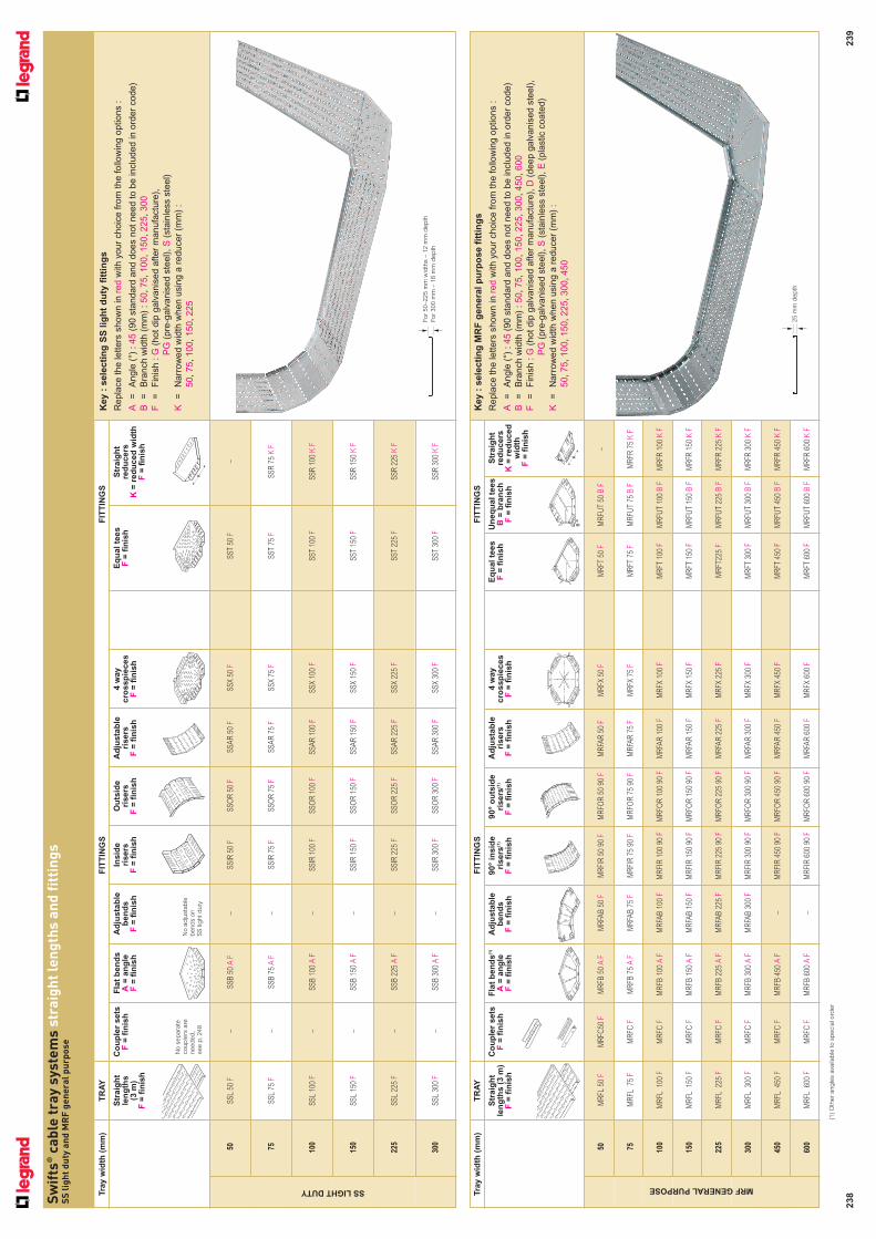
238Sw
ifts
®c
ab
le t
ray
sy
ste
ms
str
aig
ht
len
gth
s a
nd
fit
tin
gs
S
Sli
gh
t d
uty
an
d M
RF
ge
ne
ral
pu
rpo
se
239
TR
AY
TR
AY
FIT
TIN
GS
FIT
TIN
GS
FIT
TIN
GS
FIT
TIN
GS
Str
aig
ht
len
gth
s
(3 m
)F
=fi
nis
h
Co
up
ler
sets
F=
fin
ish
No
sep
ara
tecoup
lers
are
need
ed
,see p
.248
Fla
t b
en
ds
A=
an
gle
F=
fin
ish
Ad
justa
ble
ben
ds
F=
fin
ish
No a
dju
sta
ble
bend
s o
n
SS
lig
ht d
uty
Insid
e
risers
F=
fin
ish
Ou
tsid
e
risers
F=
fin
ish
Ad
justa
ble
risers
F=
fin
ish
4w
ay
cro
ssp
ieces
F=
fin
ish
Eq
ual te
es
F=
fin
ish
Str
aig
ht
red
ucers
K=
red
uced
wid
thF
=fi
nis
h
Tra
y w
idth
(m
m)
Tra
y w
idth
(m
m)
Key :
sele
cti
ng
SS
lig
ht
du
ty f
itti
ng
s
Re
pla
ce
th
e le
tte
rs s
ho
wn
in
re
dw
ith
yo
ur
ch
oic
e f
rom
th
e fo
llow
ing
op
tio
ns :
A=
An
gle
(°)
: 4
5(9
0 s
tan
da
rd a
nd
do
es n
ot
ne
ed
to
be
in
clu
de
d in
ord
er
co
de
)
B=
Bra
nch
wid
th (
mm
) : 5
0,7
5,1
00,1
50,2
25,3
00
F=
Fin
ish
: G
(ho
t d
ip g
alv
an
ise
d a
fte
r m
an
ufa
ctu
re),
PG
(pre
-ga
lva
nis
ed
ste
el), S
(sta
inle
ss s
tee
l)
K=
Na
rro
we
d w
idth
wh
en
usin
g a
re
du
ce
r (m
m)
:
50,7
5,1
00,1
50,2
25
SSLIGHTDUTY
SS
T 50
F–
SS
T 75
FS
SR
75
KF
SS
T 10
0 F
SS
R 1
00 K
F
SS
T 15
0 F
SS
R 1
50 K
F
SS
T 22
5 F
SS
R 2
25 K
F
SS
T 30
0 F
SS
R 3
00 K
F
50S
SL
50 F
–S
SB
50
AF
–S
SIR
50
FS
SO
R50
FS
SA
R 5
0 F
SS
X 5
0 F
75S
SL
75 F
–S
SB
75
AF
–S
SIR
75
FS
SO
R75
FS
SA
R 7
5 F
SS
X 7
5 F
100
SS
L 10
0 F
–S
SB
100
AF
–S
SIR
100
FS
SO
R 1
00F
SS
AR
100
FS
SX
100
F
150
SS
L 15
0 F
–S
SB
150
AF
–S
SIR
150
FS
SO
R 1
50F
SS
AR
150
FS
SX
150
F
225
SS
L 22
5 F
–S
SB
225
AF
–S
SIR
225
FS
SO
R 2
25F
SS
AR
225
FS
SX
225
F
300
SS
L 30
0 F
–S
SB
300
AF
–S
SIR
300
FS
SO
R 3
00F
SS
AR
300
FS
SX
300
F
Str
aig
ht
len
gth
s (
3 m
)F
=fi
nis
h
Co
up
ler
sets
F=
fin
ish
Fla
t b
en
ds
(1)
A=
an
gle
F=
fin
ish
Ad
justa
ble
ben
ds
F=
fin
ish
90°
insid
e
risers
(1)
F=
fin
ish
90°
ou
tsid
eri
sers
(1)
F=
fin
ish
Ad
justa
ble
risers
F=
fin
ish
4w
ay
cro
ssp
ieces
F=
fin
ish
Eq
ual te
es
F=
fin
ish
Un
eq
ual te
es
B=
bra
nch
F=
fin
ish
Str
aig
ht
red
ucers
K=
red
uced
wid
thF
=fi
nis
h
Key :
sele
cti
ng
MR
F g
en
era
l p
urp
ose f
itti
ng
s
Re
pla
ce
th
e le
tte
rs s
ho
wn
in
re
dw
ith
yo
ur
ch
oic
e f
rom
th
e fo
llow
ing
op
tio
ns :
A=
An
gle
(°)
: 4
5(9
0 s
tan
da
rd a
nd
do
es n
ot
ne
ed
to
be
in
clu
de
d in
ord
er
co
de
)
B=
Bra
nch
wid
th (
mm
) : 5
0,7
5,1
00,1
50,2
25,3
00
,4
50,6
00
F=
Fin
ish
: G
(ho
t d
ip g
alv
an
ise
d a
fte
r m
an
ufa
ctu
re),
D(d
ee
p g
alv
an
ise
d s
tee
l),
PG
(pre
-ga
lva
nis
ed
ste
el), S
(sta
inle
ss s
tee
l), E
(pla
stic c
oa
ted
)
K=
Na
rro
we
d w
idth
wh
en
usin
g a
re
du
ce
r (m
m)
:
50,7
5,1
00,1
50,2
25,3
00,4
50
(1)
Oth
er
ang
les a
vaila
ble
to s
pecia
l ord
er
K
KB
For
50–225 m
m w
idth
s –
12 m
m d
ep
th
For
300 m
m –
18 m
m d
ep
th
25 m
m d
ep
th

Swifts® cable tray systemsMRF general purpose return flange
Pack Cat. Nos. MRF general purpose return flange
Straight lengths – 3 m
1 MRFL 50 F 50 x 251 MRFL 75 F 75 x 251 MRFL 100 F 100 x 251 MRFL 150 F 150 x 251 MRFL 225 F 225 x 251 MRFL 300 F 300 x 251 MRFL 450 F 450 x 251 MRFL 600 F 600 x 25
Coupler and coupler sets
Use to join straight lengths
Standard couplers
1 MRFC 50 F 50 mm wide tray1 MRFC F 75 - 900 mm wide tray
Supplied in pairs
Quick bolt couplers
Supplied in packs containing 25 pairs ofcouplers and 100 coach bolts. For traywidths 300 mm and above use twoadditional coach bolts (QBF) per coupler Not available in S or D
1 MRQBC F 75 - 900 mm wide tray1 QBF Pack of 100 M6 x 12 coach bolts
Used to secure fittings to straight lengthsand used with quick bolt couplers on 300 mm and above tray widths
Fittings
All fittings have integral coupling tabs andfishplates. No couplers required
1 MRFBWF 90° bends
1 MRFBW A F 45° bends
For 50 - 300 mm wide,adjustable bends can also be used
1 MRFABW F Adjustable bends
50 - 300 mm wide only
1 MRFIRWF 90° inside riser
For other angles, useadjustable risers. Fixedangles available to special order
1 MRFORW F 90° outside riser
Pack Cat. Nos. Fittings (continued)
1 MRFAR W F Adjustable risers(inside or outside)
1 MRFXWF 4 way crosspieces
1 MRFTWF Equal tees
1 MRFUTW B F Unequal tees
1 MRFRW K F Reducers
Dimensions and technical information (p. 249-250)See selection chart (p. 238-239)
W
W
B
W
K
243
Key : selecting MRF general purpose fittings. Replace the letters shown
in red with your choice from the following options :
W= Widths (mm) : 50, 75, 100, 150, 225, 300, 450, 600
A = Angle (°) : 45 (90 does not need to be included in order code)
B = Branch width (mm) : 50, 75, 100, 150, 225, 300, 450, 600
F = Finish : G (hot dip galvanised after manufacture),
D (deep galvanised), PG (pre-galvanised steel),
S (stainless steel), E (plastic coated)
K = Narrowed width when using a reducer (mm) :
50, 75, 100, 150, 225, 300, 450
90° inside riser
MRFIR 300 PG
Straight length
MRFL 300 PG
Straight length
MFRL 300 PG
90° bend
MRFB 300 PG
D and S finishes not available in 50 mm
Additional gauges and finishes available
to special order
Contact us on 0845 605 4333
For other angles, useadjustable risers. Fixedangles available to special order

245
Pack Cat. Nos. Supports
Light duty cantilever arms
Supplied singly without fasteningsFit horizontal runs of tray and light duty(Opal) ladder to flat surfaces and Swiftrack channel. Suitable for all traywidths, as shown
1 LCA 100 F 100 mm1 LCA 150 F 150 mm1 LCA 225 F 225 mm1 LCA 300 F 300 mm1 LCA 450 F 450 mm1 LCA 600 F 600 mm 1 LCA 750 F 750 mm1 LCA 900 F 900 mm
Light duty cantilever brackets
Supplied singly without fasteningsFit horizontal runs of lightly loaded tray upto 150 mm wide to flat surfaces andSwiftrack channel50 - 75 mm not available in D finish100 - 150 mm not available in D, PG or S finishes
1 LCB 50 F 50 mm 1 LCB 75 F 75 mm 1 LCB 100 F 100 mm 1 LCB 150 F 150 mm
Easi-clip
50 CKP 25 Used to connect MRF tray to Swiftrack channelZinc coated finish
Overhead hangers
Supplied singly without fasteningsSupport horizontal runs of lightly loadedtray up to 150 mm wide from overhead structuresUse M10 threaded rod
1 OH 50 F 50 mm1 OH 75 F 75 mm1 OH 100 F 100 mm1 OH 150 F 150 mm
Pack Cat. Nos. Supports (continued)
Light duty trapeze hangers
Supplied singly without fasteningsSupport horizontal runs of tray and lightduty (Opal) ladder from overhead structuresUp to 450 mm wide use M10 threadedrods. For 600 mm wide and above use M12 threaded rods
1 LTH 50 F 50 mm 1 LTH 75 F 75 mm 1 LTH 100 F 100 mm 1 LTH 150 F 150 mm
1 LTH 225 F 225 mm 1 LTH 300 F 300 mm 1 LTH 450 F 450 mm 1 LTH 600 F 600 mm 1 LTH 750 F 750 mm 1 LTH 900 F 900 mm
Stand-off brackets
Supplied singly without fasteningsFit vertical or horizontal runs of tray to vertical surfaces,floors and Swiftrack channel
1 STB 50 F 50 mm1 STB 75 F 75 mm1 STB 100 F 100 mm 1 STB 150 F 150 mm 1 STB 225 F 225 mm 1 STB 300 F 300 mm
1 STB 450 F 450 mm 1 STB 600 F 600 mm 1 STB 750 F 750 mm 1 STB 900 F 900 mm
Dimensions and technical information (p. 251)
Swifts® cable tray systemssupports
Key : selecting supports. Replace the letters shown in red with your
choice from the following options :
F = Finish : G (hot dip galvanised after manufacture),
D (deep galvanised), PG (pre-galvanised)
S (stainless steel), E (plastic coated)
LCB 150 G
LCA 300 G
OH 150 PG LTH 300 PG
STB 300 PG
STB 450 PG
CKP 25
60 mm
40 mm

246
Swifts® cable tray systemsancillary items
Pack Cat. Nos. Ancillary items
Dividers – 3 m
Supplied singly without fasteningsUsed to separate different types or groups ofcable within one cable tray run
1 MRFDV F For MRF1 SRFDV F For SRF
Earth continuity connectors
20 PTFEB Fastenings not includedUse M6 x 12 mm roofing nuts and boltsCopper braid and copper lugs both inelectrotinned finishLength between centres : 93 mmConductor area : 4 mm2
Straight closed covers
Supplied singly with fastenings andbrackets3 m lengths
1 SSCC W F For SS1 MRFCC W F For MRF1 SRFCC W F For SRF
Straight ventilated covers
Supplied singly with fastenings andbrackets3 m lengths
1 SSCV W F For SS1 MRFCV W F For MRF1 SRFCV W F For SRF
Accessory closed covers
Supplied singly with fastenings and bracketsAdd CC before the width of your completed accessory Cat. No.Examples shown are for an unequal tee with a 150 branch off a300 run, hot dip galvanised
1 SS - For SSExample : SSUT CC 300 150 G
1 MRF - For MRFExample : MRFUT CC 300 150 G
1 SRF - For SRFExample : SRFUT CC 300 150 G
Pack Cat. Nos. Ancillary items (continued)
Accessory ventilated covers
Supplied singly with fastenings and bracketsAdd CV before the width of your completedaccessory Cat. No.Examples shown are for an unequal teewith a 150 branch off a 300 run, hot dipgalvanised
1 SS - For SSExample : SSUT CV 300 150 G
1 MRF - For MRFExample : MRFUT CV 300 150 G
1 SRF - For SRFExample : SRFUT CV 300 150 G
Fishplates
Fishplates are designed for extra strengthwhen joining cable tray bedsSupplied singly without fasteningsFor assembly options(see p. 251)
1 F F For SS and SRF
1 WF F For SS, MRF and SRF
Finish renovation materials
1 AGALVPAINT Galvafroid paint 400 ml1 AEPOXYPAINT 2-pack Epoxy paste 1 litre
Dimensions and technical information (p. 251)
Key : selecting ancilliary items. Replace the letters shown in red with
your choice from the following options :
W= Widths (mm) : 50, 75, 100, 150, 225, 300, 450, 600, 750, 900
B = Branch width (mm) : 50, 75, 100, 150, 225, 300, 450, 600, 750, 900
F = Finish : G (hot dip galvanised after manufacture)
D (deep galvanised), PG (pre-galvanised)
S (stainless steel), E (plastic coated)
K = Narrowed width when using a reducer (mm) :
50, 75, 100, 150, 225, 300, 450, 600, 750
Earth continuity
PTFEB
Divider
MRFDV G
Wide fishplate
WF G
Straight closed cover
MRFCC 300 G 90° bend ventilated cover
MRFBCV 300 G
Straight ventilated cover
MRFCV 300 G

248
Swifts® cable tray systemsloading graphs
n Loading graphs
n Tray section
0·5 1·0 1·5
0
50
100
150
200
Span (m)
Max
imu
msafe
wo
rkin
glo
ad
(kg
/m)
150
300
250
The loads shown on all graphs are the safe recommended maximum loads that can be appliedand must include wind, snow and any other external forces in addition to the cable load
The graphs show the maximum load for tray installed at a support spacing within itsrecommended range
When the graph line is above the intersection of the required load and span lines, the supportequipment is suitable for use within those load and span conditions
On wider MRF and SRF trays themaximum safe working load can beincreased by fitting an appropriatefishplate across the underside ofeach tray-to-tray joint
unacceptable
acceptable
Example
8
4
SS
SRF
(1) W = For widths see selection charts (p. 238-241)
(2) SRFL 600 – tested with fishplates
1·0 1·5 2·00
Span (m)
Maxim
um
safe
wo
rkin
glo
ad
(kg
/m)
50
100
200
250
150
150
600
300
MRF25 mm depth
W(1)
For 50–225 mm widths – 12 mm depth
For 300 mm and above – 18 mm depth
W(1)
(2)
1·5 2·0 2·50
Span (m)
Max
imu
msafe
wo
rkin
glo
ad
(kg
/m)
150
300
600150
50
100
200
250
W(1)
50 mm depth

249
Swifts® cable tray systemsSS and MRF
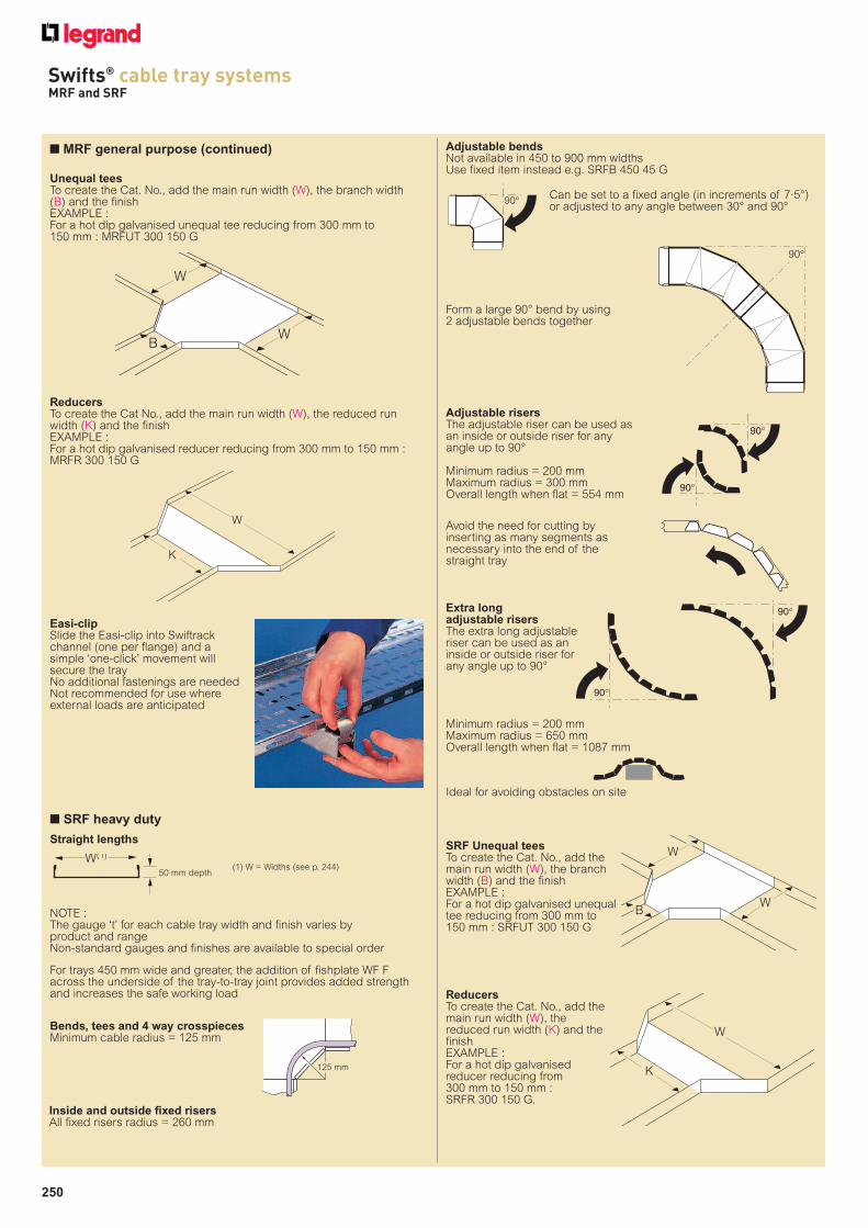
n MRF general purpose
NOTE :The gauge ‘t’ for each cable tray width and finish varies by product and rangeNon-standard gauges and finishes are available to special order
For trays 450 mm wide and greater, the addition of fishplate WF Facross the underside of the tray-to-tray joint provides added strengthand increases the safe working loadNOTE :
The gauge ‘t’ for each cable tray width and finish varies by product and rangeNon-standard gauges and finishes are available to special order
Adjustable risersThe adjustable riser can be used asan inside or outside riser for anyangle up to 90°
Minimum radius = 200 mmMaximum radius = 300 mmOverall length when flat = 554 mm
Adjustable bendsNot available in 450 mm widths and aboveUse fixed item instead e.g. MRFB 450 30 G
Can be set to a fixedangle (in incrementsof 7·5°) or adjustedto any angle between30° and 90°
Form a large90° bend by using2 adjustable bendstogether
Avoid the need for cutting byinserting as many segments asnecessary into the end of thestraight tray
90°
90°
90°
90°
Straight lengths
n SS light duty
Straight lengths
t
50 to 225 mm
12
t
18
300 mm
For SS tray cut to length use fishplates across tray-to-tray joint (see p. 251)
50 - 300 mm width fishplate F F
Bends, tees and 4 way crosspiecesAll bends, tees and crosspieces have 50 mm radius
Adjustable risersThe adjustable riser can be used as an inside or outside riser for anyangle up to 90°
Minimum radius = 200 mmMaximum radius = 300 mmOverall length when flat = 554 mm
90°
90°
Inside and outside fixed risersInside and outside risers are not available in PG finish, use adjustablerisers for all angles from 0° to 90°, reference SSAR W F
Inside and outside fixed risersAll fixed risers radius = 260 mm
ReducerTo create the Cat. No., add the main run width (W), to the reduced runwidth (K) and the finishEXAMPLE :For a hot dip galvanised reducer reducing from 300 mm to 150 mm :SSR 300 150 G.
Bends, tees and 4 way crosspiecesMinimum cable radius = 125 mm
125 mm
Width (mm) Radius (R) (mm)
50 to 150 75
225 to 300 150
For 50–225 mm widths – 12 mm depth
For 300 mm – 18 mm depth
W(1)
W
K
25 mm depth
W(1)
(1) W = Widths (see p. 243)
(1) W = Widths (see p. 242)
250
Swifts® cable tray systemsMRF and SRF
Inside and outside fixed risersAll fixed risers radius = 260 mm
NOTE :The gauge ‘t’ for each cable tray width and finish varies by product and rangeNon-standard gauges and finishes are available to special order
Ideal for avoiding obstacles on site
Avoid the need for cutting byinserting as many segments asnecessary into the end of thestraight tray
Extra long adjustable risersThe extra long adjustableriser can be used as aninside or outside riser forany angle up to 90°
Minimum radius = 200 mmMaximum radius = 650 mmOverall length when flat = 1087 mm
Bends, tees and 4 way crosspiecesMinimum cable radius = 125 mm
125 mm
Adjustable risersThe adjustable riser can be used asan inside or outside riser for anyangle up to 90°
Minimum radius = 200 mmMaximum radius = 300 mmOverall length when flat = 554 mm
90°
90°
90°
90°
Adjustable bendsNot available in 450 to 900 mm widthsUse fixed item instead e.g. SRFB 450 45 G
Can be set to a fixed angle (in increments of 7·5°)or adjusted to any angle between 30° and 90°
Form a large 90° bend by using2 adjustable bends together
90°
90°
n SRF heavy duty
Straight lengths
For trays 450 mm wide and greater, the addition of fishplate WF Facross the underside of the tray-to-tray joint provides added strengthand increases the safe working load
Unequal teesTo create the Cat. No., add the main run width (W), the branch width(B) and the finishEXAMPLE :For a hot dip galvanised unequal tee reducing from 300 mm to 150 mm : MRFUT 300 150 G
ReducersTo create the Cat No., add the main run width (W), the reduced runwidth (K) and the finishEXAMPLE :For a hot dip galvanised reducer reducing from 300 mm to 150 mm :MRFR 300 150 G
Easi-clipSlide the Easi-clip into Swiftrackchannel (one per flange) and asimple ‘one-click’ movement willsecure the trayNo additional fastenings are neededNot recommended for use whereexternal loads are anticipated
W
BW
K
W
50 mm depth
W(1)
(1) W = Widths (see p. 244)
SRF Unequal teesTo create the Cat. No., add themain run width (W), the branchwidth (B) and the finishEXAMPLE :For a hot dip galvanised unequaltee reducing from 300 mm to 150 mm : SRFUT 300 150 G
W
BW
ReducersTo create the Cat. No., add themain run width (W), thereduced run width (K) and thefinishEXAMPLE :For a hot dip galvanisedreducer reducing from 300 mm to 150 mm :SRFR 300 150 G.
K
W
n MRF general purpose (continued)

251
Swifts® cable tray systemssupports
SWL (kgf(1))Cat. Nos. A L surface
LCA 100 F 30 140 120(2)
LCA 150 F 30 190 120(2)
LCA 225 F 45 265 150
LCA 300 F 45 340 150
LCA 450 F 75 490 150
LCA 600 F 125 640 300
LCA 750 F 175 790 300
LCA 900 F 225 940 300
n Light duty cantilever arms
n Light duty cantilever brackets
n Overhead hangers
n Light duty trapeze hangers
n Stand-off brackets
Supplied singly without fasteningsFit horizontal runs of tray and light duty (Opal) ladder to flat surfacesand Swiftrack channel. Suitable for all tray widths
Supplied singly without fasteningsFit horizontal runs of lightly loaded tray up to 150 mm wide to flatsurfaces and Swiftrack channel
Supplied singly without fasteningsSupport horizontal runs of lightly loaded tray up to 150 mm wide fromoverhead structure. Use M10 threaded rod
Supplied singly without fastenings. Support horizontal runs of tray andlight duty (Opal) ladder from overhead structures. Up to 450 mm wideuse M10 threaded rods. For 600 mm wide and above use M12threaded rods
Supplied singly without fastenings. Fit vertical or horizontal runs of trayto vertical surfaces, floors and Swiftrack channel
Central hole in flangeequispaced on 600 to900 mm wide brackets
(8) Per stand-off bracket for load uniformlydistributed across the tray
(1) Per cantilever arm for load uniformlydistributed across complete armusing two fixing holesSafety factor : 2
(2) When one fixing hole is used therecommended safe working load = 100 kgf
(3) 50 - 75 mm not available in D finish
(4) 100 - 300 mm not available inD, PG and S
(5) Per bracket for load uniformlydistributed across completebracket
(6) Per hanger for load uniformlydistributed across tray widthSafety factor : 2
Trapeze hanger to threadedrod fixing
(7) Per hanger for load uniformlydistributed across complete hangerSafety factor : 2
40
L
A
Ø11 HOLES
A
50-300 mm 450-900 mm
Ø11 HOLES
IN CENTRE
SLOTS
450-900 mm
A
Ø11 HOLESØ11 HOLES
L
AA
50-75 mm 100-150 mm
Ø11 HOLES
IN CENTRE SLOTS
25x8 SLOTS
S
50-150 mm
225-450 mm
A
A
Ø11 HOLES
IN CENTRE SLOTS
Ø11 HOLES
600-900 mm Ø14 HOLES
SWL (kgf(5))Cat. Nos. A L surface Swiftrack
LCB 50(3) F 37 50 15 15
LCB 75(3) F 37 75 15 15
LCB 100(4) F 45 105 20 20
LCB 150(4) F 45 150 20 20
A SWL, Cat. Nos. (kgf(7))
LTH 50 F 75 100
LTH 75 F 112 100
LTH 100 F 150 100
LTH 150 F 187 100
LTH 225 F 280 200
LTH 300 F 355 270
LTH 450 F 505 300
LTH 600 F 660 300
LTH 750 F 810 300
LTH 900 F 960 300
Tray range Tray width Cat. No.
SS 50–300 F F
MRF 450–600 WF F
SRF 450–900 WF F
SWL (kgf(8))Cat. Nos. A horizontal vertical
tray run tray run
STB 50 F 82 40 –
STB 75 F 120 40 –
STB 100 F 157 40 –
STB 150 F 195 40 –
STB 225 F 273 100 –
STB 300 F 349 100 –
STB 450 F 485 150 150
STB 600 F 635 150 150
STB 750 F 785 150 150
STB 900 F 935 150 150
Cat. Nos. SWL (kgf(6))
OH 50 F 25
OH 75 F 50
OH 100 F 50
OH 150 F 50
n Ancillary items and standard fastenings
DividersSupplied singly without fastenings. Used to separate different types orgroups of cable within one cable tray run
Earth continuity connectorsFastenings not included. Use M6 x 12 mm roofing nuts and boltsCopper braid and copper lugs both in electrotinned finish.Length between centres : 93 mm. Conductor area : 4 mm2
Straight closed coversSupplied singly with fastenings and brackets. Covers 600 mm andabove are overlap jointed and dimpled for rigiditySSL light duty tray closed covers are only available in widths 300 mm and above
Straight ventilated covers
Accessory closed coversSupplied singly with fastenings and bracketsSSL light duty tray closed covers are only available in widths 300 mm and above
Accessory ventilated coversSupplied singly with fastenings and bracketsSS ventilated covers are only available in widths 75 mm and above
FishplatesSupplied singly without fastenings.Fishplates are designed for usewhen joining larger widths of MRFand SRF cable tray and all widthsof SS cable tray which have beencut to length.They fit across the underside ofthe tray joint to provide addedstrength and increase the safeworking load. They also greatlyenhance the lateral rigidity of thejoint and prevent unevenness inthe bed between adjacent trays
Supplied singly with fastenings3 m lengthsCovers 600 mm and above are overlapjointed and dimpled for rigiditySS ventilated covers are only available inwidths 75 mm and above