
Fuzzy Description Logics Javad Abdollahi Department of Computer Science Wayne State University.
Upload
truongduongCategory
view
216download
0
Contents lists available at ScienceDirect
Acta Astronautica
journal homepage: www.elsevier.com/locate/actaastro
The influence of coolant jet direction on heat reduction on the nose conewith Aerodome at supersonic flow
R. Moradia, M. Mosavatb, M. Barzegar Gerdroodbaryc,∗, A. Abdollahid, Younes Aminie
a Department of Chemical Engineering, School of Engineering & Applied Science, Khazar University, Baku, AzerbaijanbDepartment of Mechanical Engineering, Amirkabir University of Technology, Tehran, Iranc Department of Mechanical Engineering, Babol University of Technology, Babol, Irand Department of Mechanical Engineering, Najafabad Branch, Islamic Azad University, Najafabad, Irane Department of Chemical Engineering, Isfahan University of Technology, Isfahan, Iran
A R T I C L E I N F O
Keywords:Supersonic jetNumerical simulationCFDCoolant jetSpike
A B S T R A C T
Reduction of aerodynamic heating is a critical issue for the development of the hypersonic vehicles. In this study,a computational fluid dynamic is applied to study the effect of location of coolant jet in the vicinity of theaerodome on the heat reduction of the nose cone at M=5. In addition, the influence of the gas types (Air, Heand CO2) on the cooling performance is investigated. This research mainly focused the flow feature and massdistributions of various coolant jets. In order to study these effects, a two-dimensional model with spike is chosento simulate the various shocks in the vicinity of the nose cone. The effect of significant parameters is studied byusing the Reynolds-averaged Navier–Stokes equations with Menter's Shear Stress Transport (SST) turbulencemodel. Results show that the injection of the coolant gas from the top of aerodome significantly decreases theheat load on the nose cone. In addition, injection of the coolant jet from the top is more efficient on the re-circulation region on the top of spike. The obtained results reveal that the injection of coolant from the front ofthe aerodome does not reduce the heat load substantially. In addition, the cooling performance of helium jet asthe lateral jet is 15% more than other gases.
1. Introduction
Heat load reduction of the nose cone in the supersonic flow has beenthe main concern of the researchers to increase the speed of the hy-pervelocity vehicles. Since the aeroheating occurs due to the transfor-mation of the high enthalpy flow to stagnation point in the front of thenose cone, scientists have tried to dissipate the energy to decrease thetemperature and consequently avoid the burning of the front of the nosecone [1–5].
There are several various methods to decrease the thermal load infront of the nose cone. Some researchers [6–10] applied spike as themain simple approach to declines the heat in front of the nose cone. Theinjection of the coolant jet in front of the nose cone was also anotherefficient technique for the reduction of the heat load [11–15]. Energydeposition has also recognized as a good method for the reduction ofthe heat in the vicinity of the nose cone in the hypersonic flow [16,17].
Recently, researchers have combined the various techniques topresent a new approach for this issue. Eghlima et al. [18] investigatedheat transfer reduction using a combination of spike and counterflowjet on the blunt body at high Mach number flow. Huang [19] presented
a survey of drag and heat reduction in supersonic flows by a counter-flowing jet and its combinations. Deng et al. [20] studied drag reduc-tion investigation for hypersonic lifting-body vehicles with aerospikeand long penetration mode counterflowing jet. Huang et al. [21] stu-died drag and heat flux reduction mechanism of blunted cone withaerodisk. Sun et al. [22] presented multiobjective design optimizationof the hypersonic combinational novel cavity and the opposing jetconcept.
Among various studies, the application of the jets in front of thespike seems the most efficient approach for the reduction of the heat.Qin et al. [23] studied various injection of the coolant gas in front of thespike. They just studied flux distributions along the fluid–structuralinterfaces. This technique applied the coolant jet for pushing the frontbow shock ahead and disperse the heating of the nose of the spike. Asshown in Fig. 1, the three positions of Lateral/Oblique/Opposing jet onAerodome are close to the front of the spike and they are applied for thefront bow shock.
Previous studies performed various numerical and experimentalworks to study the main mechanism of cooling on the nose cone withspike [24–29]. Although their works are significant, they have tried to
https://doi.org/10.1016/j.actaastro.2018.06.026Received 27 May 2018; Accepted 10 June 2018
∗ Corresponding author.E-mail address: [email protected] (M. Barzegar Gerdroodbary).
Acta Astronautica 151 (2018) 487–493
Available online 15 June 20180094-5765/ © 2018 IAA. Published by Elsevier Ltd. All rights reserved.
T

present the main feature of the flow in the vicinity of the nose cone.Although these works are significant, the present of the jet in front ofthe spike induce a new flow feature that could be also significant forthis topic.
The purpose of this work is to investigate the effects of coolant in-jection in three different positions (Lateral/Oblique/Opposing) of thejet in the vicinity of the tip of the spike. In order to simulate the flowfeature and heat distribution, a computational fluid dynamic method isused to solve the Navier-Stocks equations. Also, extensive parametricstudies are performed to reveal the effects of various parameters such asthe type of coolant jet, the pressure of the jet and free stream flow.Finally, the heat performance of each position is compared and theefficient technique is comprehensively studied.
2. Numerical approach
2.1. Geometry and grid
The main geometry of the present study is obtained from the ex-perimental work of Qin [23]. The generated grid for geometry is pre-sented in Fig. 2 The diameter of the nose cone is 10 cm and the length ofspike is equal to the nose diameter. Since the model is axisymmetric,only half of the model is simulated. The size of domain in X and Ydirection is 27 cm and 10 cm, respectively. Since the main interactionsoccur in the vicinity of the aerodome, the proper grid should be gen-erated in this section. Fig. 2 illustrates the grid of the domain andpresented the close-up view to show the detail of the grid. In this study,three different grids as rough, fine and very fine grid with 10800(180×60), 14600 (220× 68) and 18400 (250× 75) are generated. Inorder to keep the quality of the grid, the height of the first layer of thegrid is kept less than 0.1mm.
2.2. Freestream and boundary condition
The freestream conditions and material properties are consistentwith those in Refs. [26,27]. The spiked blunt body is considered iso-thermal with an initial temperature of 300 K. A zero angle of attack isfixed. The inflow supersonic airstream was chosen to have the staticpressure of pascals12076 , static temperature K216 and Mach number
=∞M 5. Boundary conditions were applied to the freestream inflow(pressure far field); walls include body, spike and aerodome (no-slipwith constant temperature of 300 K); both lateral sides and top plane(symmetry planes); and outflow (pressure outlet equal to ambientpressure); injector inflow (total pressure and temperature respect tosonic inflow).
As shown in Fig. 3, the coolant gas was injected from the threedifferent regions in front, top and back wall of aerodome. The pressureof the injected coolant was selected to correspond to a total pressureratio of Jet–Air total pressure. In this study, two jet pressure ratios of0.3 and 0.6 are investigated and the jet Mach number is one.
2.3. Treatment of numerical
The simulations were performed using an implicit CFD home code[30–40]. In this code, the Navier–Stokes equations are solved by usingcell centered finite volume approach. A second-order upwind schemewas used to discretize both momentum and continuity equations with acoupled solver. The convective fluxes were treated using the Roe Flux-Difference Splitting Scheme, which has been shown to improve treat-ment and accuracy at shocks [41]. Furthermore, mesh refinement wasused to ensure proper resolution. Turbulence was modeled usingMenter's two-equation shear stress transport (SST) k-ω model [42–50].The details of SST model are presented as follows:
⎜ ⎟∂∂
+ ∂∂
= ∂∂
⎛⎝
∂∂
⎞⎠
+ − +∼ρkx
ρkux
kx
G Y St
( ) ( ) Гi
ij
kj
k k k(1)
⎜ ⎟∂∂
+ ∂∂
= ∂∂
⎛⎝
∂∂
⎞⎠
+ − + +ρωx
ρωux
ωx
G Y D St
( ) ( ) Гi
ij
ωj
ω ω ω ω(2)
The compressibility takes part in dissipation terms such as Yk andYω and partically in the production of turbulence kinetic energy isdefined as follows:
= ∗Y ρβ kωk (3)
=Y ρβωω2 (4)
Herein, β* and β are functions of F(Mt).
= +∗ ∗ ∗β β ζ F M[1 ( )]i t (5)
Fig. 1. Schematic representation of the nose cone with spike and various po-sitions of the jet injections.
Fig. 2. Generated grids.
R. Moradi et al. Acta Astronautica 151 (2018) 487–493
488

= ⎡⎣⎢
− ⎤⎦⎥
∗∗β
ββ
ζ F Mβ 1 ( )ii
it
(6)
ζ* = 1.5, and the compressibility function F(Mt) is defines as fol-lows:
= ⎧⎨⎩
≤− >
MM M
M M M MF( )
0t
t t
t t t t
02
02
0 (7)
Where,
=M kα2
t2
2 (8)
=M 0.25t0 (9)
= γRTα (10)
The term∼Gk represents the production of turbulence kinetic energy,and it is affected by compressibility as well. The equation of ∼Gk is de-fined as follows:
=∼ ∗G G ρβ kωmin( , 10 )k k (11)
In order to obtain steady state results, both the numerical residualsand the average mass fraction of a plane at 5mm at the downstream ofthe cavity are monitored. The convergence standard is based on thedifference in density values, ρ, at any grid point between two successiveiterations i.e. − ≤+ −ρ ρ 10n 1 n 4 , where n is the iteration index. Thedetail of the tuning of CFL number to obtain converged and steadyresults was comprehensively explained in our previous studies [20–26].
3. Results and discussion
In our previous studies [11–15], we comprehensively explained thatthe applied approach is inconsistent with experimental data and ob-tained results agree well with experimental data. Hence, reviewers arereferred to these paper for the validation. In order to ensure the quality
Fig. 3. Applied boundary conditions.
Fig. 4. Grid analysis.
Fig. 5. Comparison of Mach and stream line for different jet injections in Pressure Ratio of PR=0.3.
R. Moradi et al. Acta Astronautica 151 (2018) 487–493
489

of the grid and evaluate the precision of the results, three grids of ourmodel are chosen to ensure the quality of the generated grid. Accordingto obtained results in Fig. 4, the fine and very fine grid with total ele-ments of 14600 and 18400, respectively, present similar pressure var-iations on the nose cone. Therefore, fine grid is chosen for the furtherinvestigations.
3.1. Flow feature analysis of various jet positions
In order to recognize the main difference of jet injection on thecooling performance of the nose cone, the flow feature and Mach dis-tribution of these models for pressure ratio of 0.3 are compared inFig. 5. As shown in the figure, the injection of the opposing jet in frontof the aerodome does not change the flow feature and on the re-circulation region and bow shock. The injection of the oblique jet in theback of aerodome just remove the small circulation in that region andpush the bow shock away from the nose. In this model, jet could easily
extend behind the main shock and push the front shock far from theaerodome. As the jet injected from the top of aerodome, the angle ofbow shock significantly increases. Among these configurations, thismodel seems more efficient on the front bow shock.
One of the main physics associated to the different injections is thecirculation strength. In fact, this parameter significantly influences onthe flow feature and heat transfer rate in different model. Obtainedresults confirm that injection of the jet in front of the aerodome has theless effect on the circulation in the main circulation.
In order to evaluate the main effects of these arrangements, theMach contour of these models are also compared when the PR=0.6. Asshown in Fig. 6, the increasing of the total pressure of the jet sig-nificantly augments the effects and the injection of the top jet has themost effective influence on the main stream.
Fig. 6. Comparison of Mach and stream line for different jet injections in Pressure Ratio of PR=0.6.
Fig. 7. Effect of coolant jet (left CO2 and Right He) on the flow feature and Mach distribution (PR=0.6).
R. Moradi et al. Acta Astronautica 151 (2018) 487–493
490
3.2. Effect of various coolant jets
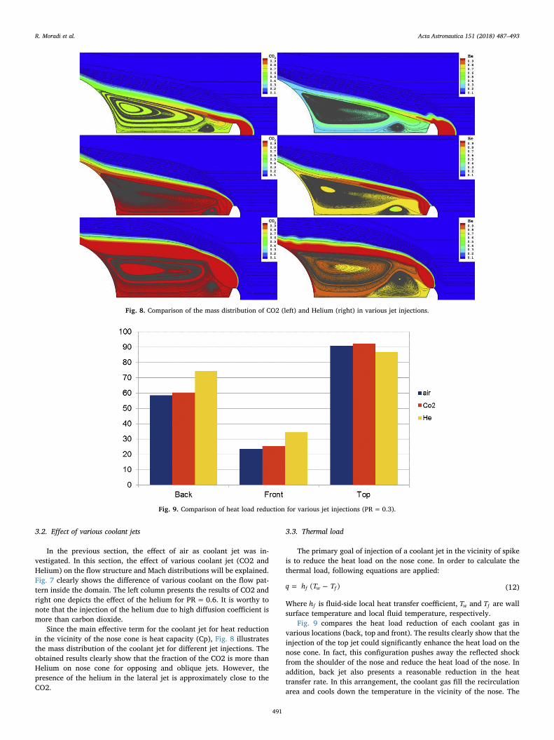
In the previous section, the effect of air as coolant jet was in-vestigated. In this section, the effect of various coolant jet (CO2 andHelium) on the flow structure and Mach distributions will be explained.Fig. 7 clearly shows the difference of various coolant on the flow pat-tern inside the domain. The left column presents the results of CO2 andright one depicts the effect of the helium for PR=0.6. It is worthy tonote that the injection of the helium due to high diffusion coefficient ismore than carbon dioxide.
Since the main effective term for the coolant jet for heat reductionin the vicinity of the nose cone is heat capacity (Cp), Fig. 8 illustratesthe mass distribution of the coolant jet for different jet injections. Theobtained results clearly show that the fraction of the CO2 is more thanHelium on nose cone for opposing and oblique jets. However, thepresence of the helium in the lateral jet is approximately close to theCO2.
3.3. Thermal load
The primary goal of injection of a coolant jet in the vicinity of spikeis to reduce the heat load on the nose cone. In order to calculate thethermal load, following equations are applied:
= −q h T T( )f w f (12)
Where hf is fluid-side local heat transfer coefficient, Tw and Tf are wallsurface temperature and local fluid temperature, respectively.
Fig. 9 compares the heat load reduction of each coolant gas invarious locations (back, top and front). The results clearly show that theinjection of the top jet could significantly enhance the heat load on thenose cone. In fact, this configuration pushes away the reflected shockfrom the shoulder of the nose and reduce the heat load of the nose. Inaddition, back jet also presents a reasonable reduction in the heattransfer rate. In this arrangement, the coolant gas fill the recirculationarea and cools down the temperature in the vicinity of the nose. The
Fig. 8. Comparison of the mass distribution of CO2 (left) and Helium (right) in various jet injections.
Fig. 9. Comparison of heat load reduction for various jet injections (PR=0.3).
R. Moradi et al. Acta Astronautica 151 (2018) 487–493
491

comparison of the type of coolant gas shows that there is not a sig-nificant difference in the heat load reduction except for the back jet.Indeed, the jet could fill the recirculation in this condition and increasethe heat capacity which decrease the heat load on the nose cone.
4. Conclusion
The primary goal of this research was to investigate the effect ofdifferent jet injections on the heat load of the nose cone. Numericalsimulations are performed to study the flow field and streamline invarious configurations. This work studied the efficient position ofcoolant gas in the nose cone. Moreover, the effect of the gas type on theflow feature and heat load reduction was comprehensively investigated.
The results display that the bow shock in front of the aerodomeplays key roles in the heat load of the nose cone. Among the variousarrangements, the injection of the coolant jet in the top of the aerodomedecrease the heat load up to 90%. According to the flow feature ana-lysis, the lateral jet pushes away the front shock and the attached wavedoes not reach to the shoulder of the nose cone. Therefore, the mainsource of the aero heating was removed from the main body and theheat load decreases. In addition, the size of the recirculation playssignificant roles in the characteristics and the cooling performance ofthe jet. Our findings show that injection from the top of the aerodomenoticeably enlarges the circulations and this is the main reason for thebetter cooling performance of this model to other ones.
References
[1] Min Ou, Yan Li, Wei Huang, Shi-bin Li, Lang-quan Li, Detailed parametric in-vestigations on drag and heat flux reduction induced by a combinational spike andopposing jet concept in hypersonic flows, Int. J. Heat Mass Tran. 126 (2018) 10–31.
[2] Tian-tian Zhang, Zhen-guo Wang, Wei Huang, Li Yan, A review of parametric ap-proaches specific to aerodynamic design process, Acta Astronaut. 145 (2018)319–331.
[3] Wei Huang, Liang Jin, Li Yan, Jian-guo Tan, Influence of jet-to-crossflow pressureratio on nonreacting and reacting processes in a scramjet combustor with back-ward-facing steps, Int. J. Hydrogen Energy 39 (2014) 21242–21250.
[4] W. Huang, L. Yan, J.G. Tan, Survey on the mode transition technique in combinedcycle propulsion systems, Aero. Sci. Technol. 39 (2014) 685–691.
[5] M. Barzegar Gerdroodbary, Numerical analysis on cooling performance of coun-terflowing jets over aerodisked blunt body, Shock Waves 24 (2014) 537–543.
[6] Shibin Li, Zhenguo Wang, Wei Huang, Shenren Xu, Li Yan, Aerodynamic perfor-mance investigation on waverider with variable blunt radius in hypersonic flows,Acta Astronaut. 137 (2017) 362–372.
[7] Tian-tian Zhang, Zhen-guo Wang, Wei Huang, Shi-bin Li, A design approach ofwide-speed-range vehicles based on the cone-derived theory, Aero. Sci. Technol. 71(2017) 42–51.
[8] M. Barzegar Gerdroodbary, S.M. Hosseinalipour, Numerical simulation of hy-personic flow over highly blunted cones with spike, Acta Astronaut. 67 (2010)180–193.
[9] Y. Amini, M. Mokhtari, M. Haghshenasfard, M. Barzegar Gerdroodbary, Heattransfer of swirling impinging jets ejected from Nozzles with twisted tapes utilizingCFD technique, Case Stud. Therm. Eng 6 (2015) 104–115.
[10] Rui-rui Zhang, Wei Huang, Li Yan, Lang-quan Li, Shi-bin Li, R. Moradi, Numericalinvestigation of drag and heat flux reduction mechanism of the pulsed counter-flowing jet on a blunt body in supersonic flows, Acta Astronaut. 146 (2018)123–133.
[11] M.B. Gerdroodbary, M. Imani, D.D. Ganji, Investigation of film cooling on nose coneby a forward facing array of micro-jets in Hypersonic Flow, Int. Commun. HeatMass Tran. 64 (2015) 42–49.
[12] M.B. Gerdroodbary, Shervin Bishesari, S.M. Hosseinalipour, K. Sedighi, Transientanalysis of counterflowing jet over highly blunt cone in hypersonic flow, ActaAstronaut. 73 (2012) 38–48.
[13] M. Barzegar Gerdroodbary, M.A. Fayazbakhsh, Numerical study on heat reductionof various counterflowing jets over highly blunt cone in hypersonic, Int JHypersonics 2 (1) (2011) 1–13.
[14] M.B. Gerdroodbary, M. Imani, D.D. Ganji, Heat reduction using conterflowing jetfor a nose cone with Aerodisk in hypersonic Flow, Aero. Sci. Technol. 39 (2014)652–665.
[15] M. Barzegar Gerdroodbary, D.D. Ganji, Y. Amini, Numerical study of shock waveinteraction on transverse jets through multiport injector arrays in supersoniccrossflow, Acta Astronaut. 115 (2015) 422–433.
[16] A. Hassanvand, M. Barzegar Gerdroodbary, Keivan Fallah, Rasoul Moradi, Effect ofdual micro fuel jets on mixing performance of hydrogen in cavity flameholder atsupersonic flow, Int. J. Hydrogen Energy 43 (2018) 9829–9837.
[17] M. Ashwin Ganesh, Bibin John, Concentrated energy addition for active drag re-duction in hypersonic flow regime, Acta Astronaut. 142 (2018) 221–231.
[18] Z. Eghlima, K. Mansour, Drag reduction for the combination of spike and coun-terflow jet on blunt body at high Mach number flow, Acta Astronaut. 133 (2017)103–110.
[19] Wei Huang, A survey of drag and heat reduction in supersonic flows by a coun-terflowing jet and its combinations, J. Zhejiang Univ. - Sci. 16 (7) (2015) 551–561.
[20] Fan Deng, Feng Xie, Ning Qin, Wei Huang, Lansong Wang, Hongyu Chu, Drag re-duction investigation for hypersonic lifting-body vehicles with aerospike and longpenetration mode counterflowing jet, Aero. Sci. Technol. 76 (2018) 361–373.
[21] Wei Huang, Lang-quan Li, Li Yan, Tian-tian Zhang, Drag and heat flux reductionmechanism of blunted cone with aerodisks, Acta Astronaut. 138 (2017) 168–175.
[22] Xi-wan Sun, Wei Huang, Zhen-yun Guo, Yan Li, Multiobjective design optimizationof hypersonic combinational novel cavity and opposing jet concept, J. SpacecraftRockets (2017) 1–10.
[23] Qihao Qin, Jinglei Xu, Shuai Guo, Reduction of aeroheating and drag using lateral/oblique/opposing jet on aerodome, J. Spacecraft Rockets 55 (2) (2017) 523–527.
[24] Tian-tian Zhang, Zhen-guo Wang, Wei Huang, Li Yan, Parameterization and opti-mization of hypersonic-gliding vehicle configurations during conceptual design,Aero. Sci. Technol. 58 (2016) 225–234.
[25] Wei Huang, Zhen-tao Zhao, Li Yan, Yun Zhou, Rui-rui Zhang, Parametric study onthe drag and heat flux reduction mechanism of forward-facing cavity on a bluntbody in supersonic flows, Aero. Sci. Technol. 71 (2017) 619–626.
[26] S. Guo, J. Xu, Q. Qin, R. Gu, Fluid–thermal interaction investigation of spiked bluntbodies at hypersonic flight condition, J. Spacecraft Rockets 53 (4) (July–Aug. 2016)629–643.
[27] Wei Huang, Yan Li, Jun Liu, Liang Jin, Jian-guo Tan, Drag and heat reductionmechanism in the combinational opposing jet and acoustic cavity concept for hy-personic vehicles, Aero. Sci. Technol. 42 (2015) 407–414.
[28] M.B. Gerdroodbary, M. Mokhtari, K. Fallah, H. Pourmirzaagha, The influence ofmicro air jets on mixing augmentation of transverse hydrogen jet in supersonicflow, Int. J. Hydrogen Energy 41 (2016) 22497–22508.
[29] M.B. Gerdroodbary, K. Fallah, H. Pourmirzaagha, Characteristics of transverse hy-drogen jet in presence of multi air jets within scramjet combustor, Acta Astronaut.132 (2017) 25–32.
[30] M. Barzegar Gerdroodbary, Younes Amini, D.D. Ganji, M. Rahimi Takam, The flowfeature of transverse hydrogen jet in presence of micro air jets in supersonic flow,Adv. Space Res. 59 (2017) 1330–1340.
[31] A. Anazadehsayed, M.B. Gerdroodbary, Y. Amini, R. Moradi, Mixing augmentationof transverse hydrogen jet by injection of micro air jets in supersonic crossflow,Acta Astronaut. 137 (2017) 403–414.
[32] M.B. Gerdroodbary, M. Mokhtari, S. Bishehsari, K. Fallah, Mitigation of ammoniadispersion with mesh barrier under various atmospheric stability conditions, AsianJ Atmos Environ 10 (3) (2016) 125–136.
[33] Keivan Fallah, M. Barzegar Gerdroodbary, Atena Ghaderi, Javad Alinejad, The in-fluence of micro air jets on mixing augmentation of fuel in cavity flameholder atsupersonic flow, Aero. Sci. Technol. 76 (May 2018) 187–193.
[34] M.B. Gerdroodbary, M.R. Takami, H.R. Heidari, K. Fallah, D.D. Ganji, Comparisonof the single/multi Transverse jets under the influence of shock wave in SupersonicCrossflow, Acta Astronaut. 123 (2016) 283–291.
[35] M. Barzegar Gerdroodbary, O. Jahanian, M. Mokhtari, Influence of the angle ofincident shock wave on mixing of transverse hydrogen micro-jets in supersoniccrossflow, Int. J. Hydrogen Energy 40 (2015) 9590–9601.
[36] M. Barzegar Gerdroodbary, Mohsen Sheikholeslami, S. Valiallah Mousavi,A. Anazadehsayed, Rasoul Moradi, The influence of non-uniform magnetic field onheat transfer intensification of ferrofluid inside a T-junction, Chem. Eng. Process:Process Intensification 123 (2018) 58–66.
[37] Mohsen Sheikholeslami, M. Barzegar Gerdroodbary, S. Valiallah Mousavi,D.D. Ganji, Rasoul Moradi, Heat transfer enhancement of ferrofluid inside an 90°elbow channel by non-uniform magnetic field, J. Magn. Magn Mater. 460 (2018)302–311.
[38] S. Valiallah Mousavi, M. Barzegar Gerdroodbary, Mohsen Sheikholeslami,D.D. Ganji, The influence of a magnetic field on the heat transfer of a magneticnanofluid in a sinusoidal channel, Eur. Phys. J Plus 131 (9) (2016) 347.
[39] A. Hassanvand, M. Barzegar Gerdroodbary, Rasoul Moradi, Younes Amini,Application of Knudsen thermal force for detection of inert gases, Results in Phys 9(2018) 351–358.
[40] M. Gerdroodbary, A. Anazadehsayed Barzegar, A. Hassanvand, R. Moradi,Calibration of low-pressure MEMS gas sensor for detection of hydrogen gas, Int. J.Hydrogen Energy 43 (2018) 5770–5782.
[41] Wei Huang, Lang-quan Li, Li Yan, Tian-tian Zhang, Drag and heat flux reductionmechanism of blunted cone with aerodisks, Acta Astronaut. 138 (2017) 168–175.
[42] F.R. Menter, M. Kuntz, R. Langtry, Ten years of experience with the SST turbulencemodel, Heat Mass Tran. 4 (2003) 625–632 Begell House Inc.
[43] Wei Huang, Jian-guo Tan, Jun Liu, Yan Li, Mixing augmentation induced by theinteraction between the oblique shock wave and a sonic hydrogen jet in supersonicflows, Acta Astronaut. 117 (2015) 142–152.
[44] Wei Huang, Shi-bin Li, Li Yan, Zhen-guo Wang, Performance evaluation andparametric analysis on cantilevered ramp injector in supersonic flows, ActaAstronaut. 84 (2013) 141–152.
[45] Wei Huang, Wei-dong Liu, Shi-bin Li, Zhi-xun Xia, Jun Liu, Zhen-guo Wang,Influences of the turbulence model and the slot width on the transverse slot in-jection flow field in supersonic flows, Acta Astronaut. 73 (2012) 1–9.
[46] Shi-bin Li, Zhen-guo Wang, Wei Huang, Jun Liu, Effect of the injector configurationfor opposing jet on the drag and heat reduction, Aero. Sci. Technol. 51 (2016)78–86.
[47] Shi-bin Li, Zhen-guo Wang, Wei Huang, Li Yan, Analysis of flowfield characteristicsfor equal polygon opposing jet on different freeflow conditions, Acta Astronaut. 133
R. Moradi et al. Acta Astronautica 151 (2018) 487–493
492
(2017) 50–62.[48] Li Shi-bin, Zhen-guo Wang, Wei Huang, Jun Liu, Drag and heat reduction perfor-
mance for an equal polygon opposing jet, J. Aero. Eng. 30 (1) (2016) 04016065.[49] Shi-bin Li, Zhen-guo Wang, George N. Barakos, Wei Huang, Rene Steijl, Research on
the drag reduction performance induced by the counterflowing jet for waverider
with variable blunt radii, Acta Astronaut. 127 (2016) 120–130.[50] Mojtaba Mokhtari, M. Barzegar Gerdroodbary, Rezvan Yeganeh, K. Fallah,
Numerical study of mixed convection heat transfer of various fin arrangements in ahorizontal channel, Eng. sci. techn, int. j 20 (3) (2017) 1106–1114.
R. Moradi et al. Acta Astronautica 151 (2018) 487–493
493


![Endosperm and Imprinting, Inextricably Linked1[OPEN] · In maize, endosperm is de-fined asESR(embryosurroundingregion, analogousto micropylar), starchy, aleurone, or BETL (basal](https://static.fdocuments.net/doc/165x107/60981ac179887c077266e563/endosperm-and-imprinting-inextricably-linked1open-in-maize-endosperm-is-de-ined.jpg)
