A Review on Immobilization of Phosphate Containing High Level Nuclear Wastes Within Glass Matrix
JOURNAL OF MATERIALS SCIENCE 32 (1997) 5851–5887
ReviewThe immobilization of high level radioactivewastes using ceramics and glasses
I . W. DONALD, B. L. METCALFE, R. N. J. TAYLORAtomic Weapons Establishment, Aldermaston, UK
An overview is given of the immobilization of high level radioactive waste (HLW) and surplus
materials from a variety of commercial and defence sources employing glass and ceramic
hosts. A number of specific host materials are reviewed, including borosilicate and
phosphate glasses, glass-ceramics and crystalline ceramics. Topics covered include
wasteform processing and manufacture, in addition to wasteform stability, durability and
mechanical behaviour. Although, at the present time, borosilicate glass is the generally
accepted first generation wasteform for the immobilization of HLW, the emergence of new
sources of radioactive materials requiring immobilization has renewed interest in many of
the alternative candidates. These include, in particular, titanate, zirconate and phosphate
based ceramics, together with iron phosphate based glasses and basaltic glass-ceramics.
The relative merits and limitations of each host material are compared and discussed, with
particular reference to processing considerations and to current and likely future
requirements.
1. IntroductionThe immobilization of highly radioactive waste mater-ials in glass or ceramic hosts has been under investiga-tion for many years (e.g. [1—38]). Until recently, mostof the available data have related to the developmentof materials for the long term storage or disposal ofhigh level nuclear waste materials either from thereprocessing of spent commercial reactor fuels, orfrom a number of defence reprocessing operations.More recently, driven partly by public concern overthe safety of nuclear power plants, particularlysince the accidents at Three Mile Island in 1979 andChernobyl in 1986, many governments have aban-doned or restricted their plans for future nuclearplants. Consequently, materials that would have beenemployed in new power plants are now less likely to berequired; therefore there is an increasing interest inimmobilizing or disposing of excess commercial stocksof uranium and plutonium fuel [39, 40]. In addition,with the ending of the Cold War, interest has alsorecently been shown in the immobilization of surplusplutonium and related materials from dismantlednuclear weapons [41—45].
Although many different types of glass and ceramicmaterials have been investigated as possible candi-dates for the immobilization of HLW, at the presenttime borosilicate glass is the generally accepted firstgeneration wasteform (e.g. [46]). As a result of thisdecision, many commercial vitrification plants arenow in operation throughout the world using borosili-cate glass as the first generation host for the immobil-ization of HLW. With the increasing demand for the
0022—2461 ( 1997 Chapman & Hall
immobilization of large quantities of HLW from manyadditional and diverse sources, there is, however,a strong incentive to reconsider many of the alterna-tive types of wasteform and to identify new candidatematerials, in particular, alternative glass composi-tions, glass-ceramic materials, and titanate and relatedceramics.
The present contribution reviews and compares themore important glass and ceramic based materialsand processes considered for the immobilization ofHLW and surplus materials, and discusses the meritsand limitations of each.
2. Types of wasteRadioactive waste is generated from a number ofsources including the reprocessing of spent fuel, cer-tain defence reprocessing operations, hospital, univer-sity and commercial research activities, industrial useof isotopes, and mining and refining of uranium ore[4, 31]. Unprocessed spent nuclear fuel may itselfrequire immobilization if the U is not to be recovered.More recently, a requirement has arisen for the immo-bilization of certain surplus materials. Some of themore important high level waste and surplus nuclearmaterials are discussed below. Typical waste constitu-ents are summarized in Tables I and II.
2.1. Nuclear reactor wastesFollowing commissioning in the UK of the first com-mercial reactor for the generation of electricity in 1956
5851

TABLE I Compos
Component Sav Sallugia Sicral 1 La Hague Magnox THORP HEWC HAWC-WAK WIP(US (Italy) (France) (France) (UK) (UK) (Belgium) (Germany) (India)
H` — 1.3M — — — — — — —Al 7 20.4 32.5 — 26.0 — 44.0 0.2 —Na 5 — 20.5 — — 0.1 1.9 16.0 6.6K 0 — — — — — — 0.4 0.2Mg 0 — 4.0 — 30.0 — — 0.2 —Fe 29 0.6 16.0 20.0 13.0 4.0 1.3 5.2 0.5Ni 2 — 1.5 3.2 1.4 — — 1.2 0.1Cr 0 — 1.5 3.4 1.6 — 0.1 1.3 0.1Mo 0 — — — 10.8 18.3 — — —Zr 0 — — — 11.8 20.1 — — —Hg 1 1.0 — — — — 2.8 — —Cl 0 — — — — — — — —SO
40 0.6 — — — — 3.2 — 0.5M
NO3
4 — — — 11.0M — — — 4.1MFPs" (3 — 24.5 87.0 — — 0.5 40.5 1.1TRUs# (0 — 3.0 5.1 2.0 4.5 0.1 6.9 7.6
!Data from [46]."FPs, fission produc#TRUs, transuranicM"Molar.THORP"ThermalHEWC"Highly enHAWC"Highly acWIP"Waste immo
58
52
ition of high level liquid wastes! (g l~1)
annah River Hanford West Valley Idaho Falls Tokai LanchowA) (USA) (USA) (USA) (Japan) (China)
— — — 2.5M 1.5M.7 1.5 3.9 4.2 — 4.5.9 4.1 10.3 3.1 44.5 31.0.3 — 0.1 0.9 — 0.6.2 — 0.3 — — —.7 6.1 20.6 — 8.4 13.5.8 0.6 0.5 — 2.2 2.9.3 0.1 0.3 — 2.2 1.2.2 0.2 — — — 0.7.6 3.4 0.4 11.4 — 0.7.8 — — — — —.9 0.1 — — — —.8 0.2 1.1 2.6 — 4.8.2 2.8 20.6 12.5 — —.0 (2.5 (1.5 (1.0 49.0 2.7.2 (0.1 (0.2 (0.1 12.6 17.9
ts.elements.
oxide reprocessing plant.riched waste concentrate.tive waste concentrate.bilization plant.
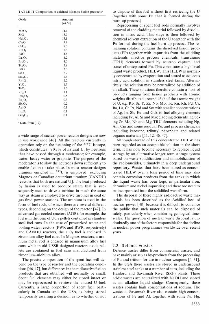
TABLE II Composition of calcined Magnox fission products!
Oxide Amount(wt %)
MoO3
14.4ZrO
213.9
Nd2O
313.1
Cs2O 9.4
CeO2
8.5RuO
27.8
BaO 4.6La
2O
34.2
Pr6O
114.0
Tc2O
73.8
PdO 3.3SrO 2.9Sm
2O
32.6
Rh2O
32.2
Y2O
31.7
TeO2
1.6Rb
2O 1.1
Pm2O
30.5
Eu2O
30.3
Sb2O
30.2
Ag2O 0.1
In2O
30.1
Gd2O
30.1
!Data from [12].
a wide range of nuclear power reactor designs are nowin use worldwide [46]. All the reactors currently inoperation rely on the fissioning of the 235U isotope,which constitutes +0.7% of natural U, by neutronsthat have passed through a moderator; for example,water, heavy water or graphite. The purpose of themoderator is to slow the neutrons down sufficiently toenable fission to take place. In most reactor designsuranium enriched in 235U is employed [excludingMagnox or Canadian deuterium uranium (CANDU)reactors that both use natural U]. The heat producedby fission is used to produce steam that is sub-sequently used to drive a turbine, in much the sameway as steam is employed to drive turbines in coal orgas fired power stations. The uranium is used in theform of fuel rods, of which there are several differenttypes, depending on the design of the reactor [47]. Inadvanced gas cooled reactors (AGR), for example, thefuel is in the form of UO
2pellets contained in stainless
steel fuel cans. In the case of pressurized water andboiling water reactors (PWR and BWR, respectively)and CANDU reactors, the UO
2fuel is enclosed in
zirconium alloy fuel cans. In Magnox reactors, a ura-nium metal rod is encased in magnesium alloy fuelcans, while in old USSR designed reactors oxide pel-lets are contained in fuel cans manufactured fromzirconium—niobium alloy.
The precise composition of the spent fuel will de-pend on the type of reactor and the operating condi-tions [46, 47], but differences in the radioactive fissionproducts that are obtained will normally be small.Spent fuel elements may either be stored intact ormay be reprocessed to retrieve the unused U fuel.Currently, a large proportion of spent fuel, parti-cularly in Canada and the USA, is being storedtemporarily awaiting a decision as to whether or not
to dispose of this fuel without first retrieving the U(together with some Pu that is formed during theburn-up process.)
Reprocessing of spent fuel rods normally involvesremoval of the cladding material followed by dissolu-tion in nitric acid. This stage is then followed bychemical solvent extraction of the U together with thePu formed during the fuel burn-up process. The re-maining solution contains the dissolved fission prod-ucts (FP) together with impurities from the claddingmaterials, inactive process chemicals, transuranic(TRU) elements formed by neutron capture, andtraces of unseparated Pu. This constitutes a high levelliquid waste product, HLLW. This HLLW is normal-ly concentrated by evaporation and stored as aqueousnitric acid solution in stainless steel tanks. Alterna-tively, the solution may be neutralized by addition ofan alkali. These solutions therefore contain a host ofproducts ranging from fission products with atomicweights distributed around 46 (half the atomic weightof U; e.g. Rb, Sr, Y, Zr, Nb, Mo, Tc, Ru, Rh, Pd, Cs,Ba, La, Ce Pr, Nd and Sm with smaller concentrationsof Ag, In, Sb, Eu and Gd); to fuel alloying elementsincluding Fe, Al, Si and Mo; cladding elements includ-ing Zr, Mo, Nb and Mg; TRU elements including Np,Am, Cm and some residual Pu; and process chemicalsincluding kerosene, tributyl phosphate and relatedorganic materials [11, 12, 46, 47].
Although storage of this concentrated HLLW hasbeen regarded as an acceptable solution in the shortterm, it has now become necessary to replace liquidstorage by an alternative longer term storage systembased on waste solidification and immobilization ofthe radionuclides, ultimately in a deep undergroundrepository. Wastes that have been stored as concen-trated HLLW over a long period of time may alsocontain corrosion products from the tanks in whichthe liquid waste has been kept, in particular iron,chromium and nickel impurities; and these too need tobe incorporated into the solidified wasteform.
The disposal of these highly radioactive waste ma-terials has been described as the Achilles’ heel ofnuclear power [48] because it is difficult to convincethe public that such materials can be disposed ofsafely, particularly when considering geological time-scales. The question of nuclear waste disposal is un-doubtedly one of the factors responsible for the declinein nuclear power programmes worldwide over recentyears.
2.2. Defence wastesDefence wastes differ from commercial wastes, andhave mainly arisen as by-products from the processingof Pu and tritium for use in nuclear weapons [4, 31].In the USA these wastes are stored in undergroundstainless steel tanks at a number of sites, including theHanford and Savannah River (SRP) plants. Theseacidic wastes are neutralized with NaOH and storedas an alkaline liquid sludge. Consequently, thesewastes contain high concentrations of sodium. Thewastes at Savannah River also contain high concen-trations of Fe and Al, together with some Ni, Hg,
5853

chloride, sulphate and nitrate; while the wastes atHanford contain Fe, Zr, Al and nitrate. Smaller quant-ities of waste from the reprocessing of fuel from navalreactors are stored as calcined products at the Idahochemical processing plant (ICPP). These wastes con-tain high concentrations of nitrate, together with Zr,Na, Al and sulphate. With the exception of the navalreactor waste, the defence wastes do not in generalcontain high concentrations of fission products, andthey may therefore be considerably less radioactivethan their commercial equivalents.
2.3. Surplus materialsInterest in the immobilization of excess stocks of com-mercial and military materials, including uranium andplutonium, has grown considerably in recent years,particularly with the ending of the Cold War. Both theUSA and former USSR currently have comprehensiveprogrammes aimed at examining methods that may besuitable for the immobilization of these excess mater-ials in a safe, proliferation-resistant form that willprevent their recovery for weapon use. In the USAa number of immobilization strategies have been ad-dressed for this special category of material [49—57].The most important include storing the material in itscurrent form in safe guarded vaults, using the materialas a mixed oxide (MOX) fuel in nuclear reactors,irradiation of material in a fission reactor to producealternative less radioactive wasteforms, vitrifying thematerial in a borosilicate glass, and immobilization asan oxide ceramic wasteform.
3. Immobilization of radioactive wasteIn general, UK commercial wastes contain high con-centrations of Al, Mg, Zr, Mo and Fe, while materialsfrom the USA, which mainly consist of defence wastes,contain high concentrations of nitrate, Fe, Na and Al.French waste products can also be high in Al, Na andFe; while Chinese waste is high in Na, TRU elements,Fe and sulphate; and Indian waste is high in Na,nitrate, phosphate and TRU elements. Japanese ma-terials are particularly high in Na and TRU elements.Details of waste compositions are summarized inTables I and II.
The rationale behind the immobilization of radioac-tive waste materials in glass or ceramic hosts is toprovide a solid, stable and durable material that canbe more easily stored or disposed of than the currentliquid wastes. Immobilization may be accomplishedeither by dissolution of the waste elements on anatomic scale within the host lattice, or by encapsula-tion of the waste within an inert matrix. Wasteformscan be temporarily stored at the solidification process-ing plant (during which time the heat generated by thedecay of the fission products decreases), but the longerterm strategy is to dispose of them permanently in anunderground repository as part of a multibarrier ap-proach. The immobilized waste would therefore formonly one part of an engineered system designed toprevent contamination of the biosphere with radioac-tive elements.
5854
Figure 1 Schematic illustrations of different wasteforms: (a) homo-geneous glass, with some bubbles and inclusions; (b) waste particlesencapsulated in a glass matrix; (c) ceramic wasteform with wastephases in solution; and (d) ceramic with encapsulated waste phases.
Proposed repository or vault designs consist ofa number of deep boreholes (at a depth of around300—1000m), possibly including interconnected galle-ries, in which the solidified waste contained in metalcanisters would be buried [12, 18]. The canisterswould be surrounded by an overpack material that inturn would most probably be surrounded by an inertoverfill. Three types of geological formations havebeen suggested as suitable for the construction ofa repository, namely salt, clay and hard rock (graniteor basalt). The rationale behind the choice of salt isthat there are salt deposits throughout the world thathave remained stable for millions of years. Clay offersthe advantage of being extremely impervious to water,while granite or basaltic rock formations are found indeep geologically stable environments. The overpackmaterial would consist of a corrosion resistant metal,such as Ti, or a thicker layer of an iron alloy thatwould corrode at a slow, predictable rate. The backfillis likely to be composed of a clay with a low permeab-ility to water or, alternatively, a cementitious material.Assuming the resulting vault remains undisturbed (i.e.there are no earthquakes or related phenomena), theonly mechanism by which radionuclides could reachthe biosphere would be by dissolution of the waste-form in groundwater, followed by migration of theradioactive solution to the surface. It follows that oneof the major factors in selecting a wasteform materialfor ultimate disposal in an underground repository isits resistance to leaching by groundwater that mayeventually penetrate the repository environment.
Many different types of glass and ceramic waste-forms have been studied over a long period oftime, and a number of evaluation studies have beenconducted around the world. Some of the wasteformsconsidered include borosilicate, aluminosilicate,high silica and phosphate glasses, silicate-based glass-
ceramics, titanate-based crystalline ceramics, alumina-based ceramics, clay-based materials, and variousforms of cement and concrete. Wasteforms have beenexamined in which the radionuclides and other wasteelements are incorporated directly into the wasteformlattice on an atomic scale as solid solutions, in addi-tion to forms in which the wastes are incorporatedmacroscopically into a separate matrix phase, whichmay be either metallic or non-metallic, to form a com-posite material. Some generic forms are shownschematically in Fig. 1.
4. Immobilization as a vitreouswasteform
4.1. BackgroundImmobilization of high level nuclear wastes by vitrifi-cation is a well established process that has beenstudied extensively over the last 40 years in the UK,Germany, Italy, Canada, USA, former USSR, Indiaand Japan [10, 12, 18, 46]. A suitable glass host is usedto dissolve the HLW to form a glassy (vitreous) homo-geneous product that can be cast into suitable forms,including large glass blocks. Under suitable condi-tions, it is possible to incorporate up to 25—30 wt%HLW into a glass. The choice of glass composition isa compromise between high HLW solubility, manage-able glass formation temperature, and low leachabilityin repository environments. Various glass systemshave been shown to be suitable for producing wasteglass forms that are thermally and mechanically stableand exhibit good chemical durability. The main ad-vantages of the vitrification route include the fact thatglass is a good solvent for HLW; glass can be pro-cessed at reasonably low temperatures; glass is verytolerant of variations in waste composition; glass ex-hibits reasonable chemical durability; and glass isradiation resistant and can accommodate changes oc-curring during radioactive decay of HLW constitu-ents. The technology for preparing glass wasteforms,both in laboratory size samples and multitonne forms,is well established and vitrification plants are opera-tional throughout the world. Many tonnes of HLWimmobilized in glass are currently in interim storage atvarious vitrification plants awaiting the constructionof suitable underground repositories for their perma-nent disposal.
The potential use of glass as a nuclear wasteformwas initially investigated in the early 1950s in Canadausing a natural silicate mineral, nepheline syenite, asthe starting material [10]. This was mixed with anacidic solution of the waste material together withlime, and the mixture melted at 1250—1350 °C in a fire-clay crucible. An active pilot plant was subsequentlyconstructed at Chalk River in order to demonstratethe feasibility of the vitrification process on a largerscale. Radioactive blocks of glass were producedbetween 1958 and 1960. The development of glasswasteforms was terminated in 1960 because no fuelreprocessing was foreseen in Canada at that time;a new programme was not initiated until 1976.
In the UK also, work started in the 1950s, initiallyusing natural soils as the base material for glass
formation [10]. These glasses had to be melted at veryhigh temperatures (about 1500 °C) in order to producehomogeneous, bubble-free products. Subsequently, al-kali borosilicate glass compositions were developedthat could dissolve up to 30% waste oxides and thatcould be melted at lower temperatures. Between 1958and 1962 a vitrification pot process was developed atthe UK Atomic Energy Authority’s Harwell laborat-ory called the fixation in glass of active liquors(FINGAL) process. This process involved calciningand then melting HLW together with glass frit ina stainless steel crucible or pot, with the pot sub-sequently serving as the storage container. After theglass and waste had been calcined, melted and hom-ogenized, the pot was removed and replaced withanother pot containing waste and frit ready to becalcined and melted. The FINGAL process was latermodified and scaled up, becoming known as the high-ly active residue vitrification experimental studies(HARVEST) process.
Although these and other related glass wasteformpot manufacturing processes were successful in pilotplant trials, batch processing considerations ledFrance to choose a continuous melting process for fullscale development. The French process has the addi-tion of a separate calcining stage [46]. Waste is firstcalcined employing a rotary kiln before being fedunder gravity into a metallic pot heated inductively.This is a continuous process with new glass frit andwaste material being supplied to the furnace and mol-ten glass being fed from the furnace via a freeze—thawvalve directly into a separate storage canister. Themajor advantage of this process is that much higherthroughputs can be achieved. Radioactive operationof an industrial pilot plant initially commenced in1968 at Marcoule in France, and full scale operationstarted in 1978. This particular method is now knownas the atelier de vitrification de Marcoule (AVM)process. Similar plants have since been built at LaHague in France. The advantages offered by the AVMprocess, coupled with its successful full scale operationin France, led the UK (British Nuclear Fuels Limited,BNFL) to choose this process, in preference to theHARVEST method, for its commercial waste vitrifica-tion plant at Sellafield [58].
An alternative continuous process has been de-veloped using a Joule-heated ceramic melter [46]. Inthis process the glass is melted in a tank constructedfrom refractory ceramic blocks by passing an electriccurrent through the molten glass using submergedelectrodes. Calcined HLW mixed with glass frit maybe fed into the furnace from a rotary calciner, similarto the AVM method, or, alternatively, a slurry ofwaste and frit may be added directly to the furnace,with evaporation and calcination occurring within thefurnace environment, as in the pot process. A highlyviscous glassy layer forms at the walls of the ceramiccontainment vessel so that, in effect, the glass itself actsas its own crucible. A major advantage of this methodis that it does not produce a large number of con-taminated crucibles or furnaces. In addition, becausecold material covers the surface of the molten glass,evaporation losses, particularly from volatile fission
5855
elements, such as Ru and Cs, are minimized. The firstlarge scale development of a ceramic melter for vitrifi-cation of HLW was carried out at Battelle PacificNorthwest Laboratories (PNL) in the USA wherea pilot plant was commissioned for radioactive use in1984. A ceramic melter was also commissioned forradioactive work in 1985 at Mol in Belgium. Furtherlarge scale ceramic melters are under construction atSavannah River and West Valley in the USA andTokai in Japan. A related process employs a coldcrucible induction melter. In this method the glass fritis melted in a water cooled metal crucible. As in thecase of Joule heating, the melt does not come intodirect contact with the crucible.
More recently, attention has been turned to theimmobilization of excess uranium and plutoniumfrom commercial operations and dismantled nuclearweapons using glass or ceramic hosts. Articles on thepotential use of vitrification techniques for the immo-bilization of weapons plutonium have recently ap-peared in the popular press, including New Scientist[41, 42]. Immobilization of fissile materials introducesadditional considerations, in particular the question ofcriticality, which are discussed later.
Many different families and compositions of glasshave been studied since the 1950s, when the idea ofusing glass as a wasteform host was first considered.Some of the more important of these are discussed inthe following sections.
4.2. Glass requirements4.2.1. Glass-forming abilityIt is now generally recognized from the kinetic theoryof glass formation that most materials are glass form-ing, providing that the cooling rate is high enough toavoid crystallization, and the final ambient temper-ature on cooling is below the glass transition temper-ature, ¹
', of the material (see e.g. [59]). There are,
however, a number of categories of material that willform glasses readily without having to impose a rapidquench rate, including certain oxides, chalcogenidesand salts. In fact, many of these materials will formglasses at very low cooling rates, often (0.1K s~1,and these materials can be produced in bulk form byconventional casting routes. An important parameterin glass technology is the critical cooling rate for glassformation, R
#, that for any given material is the min-
imum cooling rate required to avoid crystallization.This can be calculated from kinetic data, usually byconstructing time—temperature—transformation (TTT)or continuous cooling transformation (CCT) curves.The value of R
#is given by the minimum cooling rate
required in order just to by-pass the nose of the TTTor CCT curve. The smaller the value of R
#, the larger
the cross-section of material that can be producedin a glassy form without crystallization occurring.Glasses for the immobilization of HLW must ingeneral be capable of being cast into relatively largeblanks without crystallizing, so that candidate glassesmust possess low critical cooling rates for glassformation. These topics are considered more fully inSection 9.1.
5856
4.2.2. Thermal stabilityGlassy materials are, of course, metastable with re-spect to temperature and time (see e.g. [59]). Thethermal stability of a glass is therefore of additionalpractical importance. The glass must be sufficientlystable to enable the glass to be annealed withoutcrystallization occurring. In general, all glasses willcrystallize if heated at a sufficiently high temperaturefor a sufficiently long period of time. Usually thiscrystallization proceeds in an uncontrolled manner bynucleation of large crystals from external surfaces, andthis leads to the formation of undesirable stresses thatmay cause the glass to crack. Thermal stability isparticularly important in the case of glasses to be usedfor the immobilization of HLW because poor stabilitymay lead to the formation of crystals either duringannealing of the glass, or during its time in storage. Ifserious cracking of the glass subsequently occurs,leaching rates may be significantly enhanced. This isalso considered more fully in Section 9.1.
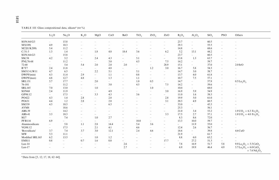
4.3. Types of glass4.3.1. Borosilicate glassesSilicate glasses have long been the preferred waste-form for the immobilization of HLW. This is becausethey readily dissolve a wide range of waste composi-tions and they can be easily modified in order tooptimize their properties. In addition, they form thebasis of the commercial glass industry, and have beenstudied extensively for many years. They are, there-fore, well characterized and their properties are wellknown and understood.
Ideally, the most durable wasteform would be vit-reous silica, but this material requires too high a pro-cessing temperature. Commercial glass compositionstherefore reflect a compromise between glass durabil-ity, processing ability and economics. Boric oxide ismost commonly employed to modify the behaviour ofsilica, this additive substantially lowering the process-ing temperatures required for glass formation andworkability, while maintaining good durability withingiven composition ranges. As a result of a number ofearly studies, borosilicate glass has become the firstchoice of material worldwide for the immobilization ofnuclear waste materials, and it is the only qualified‘‘reference’’ HLW wasteform at the present time. Thisselection was based on the flexibility of borosilicateglass with regards to waste loading and the ability toincorporate many different kinds of waste elements,coupled with good glass-forming ability, chemicaldurability, mechanical integrity, and excellent thermaland radiation stability. Compositions studied havegenerally concentrated on the sodium borosilicate sys-tem with minor additions of other modifying oxides,including alumina, lithia, calcia and zinc oxide. A verylarge data base has now been established for borosili-cate glasses for the immobilization of HLW, withextensive information available on the processingcharacteristics, durability and corrosion behaviour,mechanical performance, thermal stability includingdevitrification behaviour, and radiation stability (e.g.[10, 12, 60, 61]).
More recently, attention has been turned to thepossible use of borosilicate glass as a host for highconcentrations of actinides, in particular surplusplutonium and uranium from both civil and militaryoperations. For example, Taylor et al. [40] have sum-marized the findings of a study aimed at identifyingmaterials for the disposal of stocks of waste plutoniumfrom civil operations. A number of different waste-forms were considered in this study. It was concludedthat borosilicate glass offered the preferred wasteformoption for applications involving the immobilizationof plutonium. This was despite the fact that theseglasses have been designed specifically as solvents toaccommodate high concentrations of reactor fuelelements and fission products, and the solubility ofactinide elements was relatively low, i.e. (3 wt%.Use of borosilicate glass has also been proposed forthe immobilization of excess Pu from dismantled nu-clear weapons [50].
Compositional data and selected properties fora number of borosilicate glasses that have been con-sidered for the immobilization of HLW are sum-marized in Tables III, IV and V, respectively.
4.3.2. Phosphate glassesAlthough the majority of glasses studied to date forthe immobilization of HLW have been based onborosilicate compositions, some work has also beenreported on phosphate systems [65—72]. The atomicbonding characteristics of phosphate glasses in manyrespects more closely resemble organic polymers thansilicate networks, and this leads to many differences inproperties between the two families of glasses [73]. Ingeneral, phosphate based glasses are less stablethermally than their silicate equivalents and they areconsiderably less durable, particularly in aqueous en-vironments, although there are some notable excep-tions. They also exhibit lower melting temperatures,lower melt viscosities and substantially different tem-perature—viscosity behaviour.
Interest in phosphate glasses was high during theearly immobilization studies, due in part to the rela-tively low formation temperatures required, coupledwith their high solubility for sulphates and metal ox-ides (sulphates cause phase separation of silicate glass-es and lead to a decrease in durability due to theformation of a soluble phase). Interest in phosphateglasses quickly declined, however, due to a combina-tion of factors. These included the very poor chemicaldurability of the early compositions, coupled withtheir low thermal stability. In addition, phosphatemelts are normally highly corrosive in nature, signifi-cantly more so than their silicate equivalents, and thisis a factor that would seriously limit melter lifetime.Improved reprocessing also led to HLLW low insulphate, so that high sulphate solubility was nolonger required. Some work did continue, however,mainly in Europe (and particularly in the formerUSSR). A number of sodium aluminophosphate, ironaluminophosphate and zinc phosphate compositionswere subsequently developed that exhibited improvedchemical durabilities, although their thermal stabili-
ties were still relatively low and they remained highlycorrosive.
More recently, a new family of lead iron phosphateglasses has been developed at Oak Ridge NationalLaboratory in the USA. These glasses have beenshown to exhibit good glass-forming characteristics,together with reasonable thermal stabilities andexcellent chemical durabilities. In addition, thesenewer melts are not as corrosive as the earlierphosphate compositions. Lead iron phosphate glassescan be prepared at temperatures in the range800—1000 °C, which is some 100—250 °C lower thanthe borosilicate compositions currently employedfor immobilization of HLW, although it has beenreported that a temperature of at least 1000 °Cis required in order to dissolve HLW fully. It hasbeen noted that the thermal stabilities of these glasses,although improved, are still not as good as those ofthe borosilicates. It is therefore unlikely that canisterssimilar in size to those currently used for borosilicateimmobilized HLW could be employed withoutcrystallization of the phosphate glass occurring.Although leach rates have been reported to be10—1000 times lower than for the borosilicate com-positions, once some initial crystallization of thesephosphate glasses has been allowed to occur durabil-ity decreases markedly. In addition, durability inaqueous solutions also decreases markedly at temper-atures '100 °C, which may be important when con-sidering repository environments where temperaturesmay significantly exceed this figure. There is someevidence to suggest that increasing the Fe
2O
3content
of the glass, while reducing PbO, increases the glassdurability, particularly in saline solutions, but morework is required in this area before definitive con-clusions may be drawn. It has also been noted thataddition of CaO to iron phosphate glasses improveddurability [74].
The solubilities of actinide oxides in phosphateglasses are significantly higher than the solubilitiesassociated with borosilicate compositions. Phosphateglasses, particularly those based on lead iron phos-phate, would therefore appear to offer considerablepromise for the newer applications involving immobil-ization of plutonium both from dismantled nuclearweapons and from curtailed civil operations.
Compositional data and selected properties fora number of phosphate glasses considered for theimmobilization of HLW are summarized in Tables III,IV and V, respectively.
4.3.3. Rare earth oxide glassesOnly limited work has been reported in the area ofrare earth oxide glasses for immobilization applica-tions, but one commercial lanthanide borosilicatecomposition has been considered. This glass, de-scribed as ‘‘Loffler’’ glass, was developed originally asan optical glass in the 1930s and contained 55wt% oflanthanide oxides. It has recently been suggested asa potential host for the immobilization of U, Pu andAm [62], exhibiting a higher solubility for theseelements than conventional borosilicate glass.
5857
TA
ZnO B2O
3Al
2O
3SiO
2PbO Others
SO — 23.7 — 60.5 — —M5 — 29.3 — 55.5 — —M2 — 14.8 — 68.6 — —C/3 6.2 5.2 13.1 44.2 — —SO — 23.7 — 60.5 — —SM — 13.8 1.3 63.7 — —PN 7.5 14.2 — 59.7 — —72- 28.9 15.1 — 37.0 — 2.0 SrOR7 3.0 16.7 5.8 54.3 — —SM — 14.7 3.0 58.7 — —DW — 13.7 4.0 61.8 — —DW — 10.7 7.5 57.1 — —SR — 14.7 — 57.9 — 0.5La
2O
376- 7.5 14.2 — 59.6 — —SR — 10.0 — 68.0 — —SO 3.0 16.9 5.9 54.9 — —GP — 11.0 1.6 58.5 — —PO 2.8 19.9 5.0 61.0 — —PO 3.1 20.3 4.9 60.5 — —SM — 33.0 — 45.5 — —AV — 25.3 — 56.1 — —AB — 21.0 3.4 53.2 — 1.9UO
2#6.3 Fe
2O
3AB 3.3 17.5 2.7 57.1 — 1.8UO2#4.0 Fe
2O
3SG — 8.3 8.6 72.0 — —PF — 13.3 10.0 59.7 — —Alu — — 11.9 55.0 — —VG — 12.4 2.6 56.7 — —‘Bo — 18.6 — 39.8 4.6CuOMW — 21.9 — 61.7 — —Mo — 8.8 6.0 63.2 — —EM 17.7 — 27.2 51.3 — —Lan — 7.8 16.9 51.7 5.8 9.9La
2O
3#5.5CeO
2Lan — 6.9 19.9 46.4 4.9 5.7La
2O
3#6.0CeO
2#7.6Nd
2O
3
!D
58
58
BLE III Glass compositional data, silicate! (wt %)
Li2O Na
2O K
2O MgO CaO BaO TiO
2ZrO
2
N/64/G3 — 15.8 — — — — — —(189) 4.9 10.3 — — — — — —2(UK209) 5.4 11.2 — — — — — —1-3 1.3 1.4 — 1.8 4.8 18.4 3.6 —N/64-G3 — 15.8 — — — — — —/58 4.2 5.2 — 2.4 4.3 — 5.1 —L76-68 — 11.2 — — 3.0 — 4.5 —68 — 5.4 5.4 2.0 2.0 2.0 — —T7 2.4 11.8 — — 4.8 — — 1.2513-LW11 4.7 6.5 — 2.2 5.1 — 5.1 —PF(min) 4.3 11.4 2.9 — 1.1 — 0.8 —PF(max) 4.8 12.7 4.8 — 1.3 — 1.1 —
L131 5.7 17.7 — 2.0 — — 1.0 0.5101 — 11.2 — — 3.0 — 4.5 —L165 7.0 13.0 — 1.0 — — — 1.0N68 2.4 11.9 — — 4.9 — — —98/12 — 17.5 — 3.3 4.5 — 3.6 —422 4.3 1.4 2.8 — 2.8 — — —631 4.4 1.2 2.8 — 2.8 — — —539 4.5 10.5 — — 6.5 — — —M8 — 18.6 — — — — — —S-39 — 14.2 — — — — — —S-41 3.3 10.3 — — — — — —7 — 7.4 — 1.0 2.7 — — —R116 6.9 — — — — — 10.0 —minosilicate — 5.8 1.1 2.8 14.4 — 5.4 3.698/12 — 17.5 — 2.1 4.1 — 4.6 —rosilicate’ 3.7 7.4 3.7 3.0 12.1 — 2.4 4.6
5.3 11.1 — — — — — —dified SRL165 6.2 13.5 — 1.0 1.2 — — —S11 0.8 — 0.7 1.6 0.8 — — —-14 — — — — — 2.6 — —-17 — — — — — 2.7 — —
ata from [5, 12, 17, 18, 62—64].
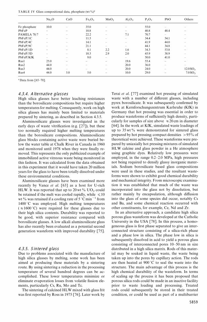
TABLE IV Glass compositional data, phosphate (wt%)!
Na2O CaO Fe
2O
3MnO
2Al
2O
3P2O
5PbO Others
Fe phosphate 10.0 — 35.0 — — 55.0 — —PbFeP — — 10.8 — — 40.8 48.4 —PAMELA 78/7 — — 22.2 — 7.1 70.7 — —PbFeP/1C — — 11.5 — — 34.4 54.1 —PbFeP/4C — — 14.1 — — 41.9 44.0 —PbFeP/9C — — 21.1 — — 44.1 34.8 —PbFeP/1D — — 8.1 2.2 1.6 34.3 53.8 —PbFeP/5D — — 10.3 2.9 2.0 45.9 38.9 —PbFeP/KfK — — 9.0 — — 50.0 41.0 —Rus1 25.0 — — — 19.6 55.4 — —Rus2 44.0 — — — 20.0 36.0 — —Rus3 44.0 — — — 20.0 24.0 — 12.0SO
3Rus4 44.0 5.0 5.0 — 10.0 29.0 — 7.0 SO
3
!Data from [65—70].
4.3.4. Alternative glassesHigh silica glasses have better leaching resistancesthan the borosilicate compositions but require highertemperatures for melting. Consequently, work on highsilica glasses has mainly been limited to materialsprepared by sintering, as described in Section 4.3.5.
Aluminosilicate glasses were investigated in theearly days of waste vitrification (e.g. [27]), but thesetoo normally required higher melting temperaturesthan the borosilicate compositions. Aluminosilicateglass blocks containing active waste were buried be-low the water table at Chalk River in Canada in 1960and monitored until 1978 when they were finally re-moved. This represents the only publicized example ofimmobilized active vitreous waste being monitored inthis fashion. It was calculated from the data obtainedin this experiment that it would have taken 20 millionyears for the glass to have been totally dissolved underthese environmental conditions.
Aluminosilicate glasses have been examined morerecently by Vance et al. [63] as a host for U-richHLW. It was reported that up to 20wt% UO
2could
be retained if the melt was cooled rapidly, while )10wt% was retained if a cooling rate of 5 °Cmin~1 from1400 °C was employed. High melting temperatures(+1600 °C) were required for these glasses due totheir high silica contents. Durability was reported tobe good, with superior resistance compared withborosilicate glasses. A low alkali aluminosilicate glasshas also recently been evaluated as a potential secondgeneration wasteform with improved durability [75].
4.3.5. Sintered glassDue to problems associated with the manufacture ofhigh silica glasses by melting, some work has beenaimed at producing these materials by a sinteringroute. By using sintering a reduction in the processingtemperature of several hundred degrees can be ac-complished. These lower temperatures minimize oreliminate evaporation losses from volatile fission ele-ments, particularly Cs, Ru, Mo and Tc.
The sintering of calcined HLW mixed with glass fritwas first reported by Ross in 1975 [76]. Later work by
Terai et al. [77] examined hot pressing of simulatedwaste with a number of different glasses, includingpyrex borosilicate. It was subsequently confirmed bywork at Kernforschungszentrum Karlsruhe (KfK) inGermany that hot pressing was essential in order toproduce wasteforms of sufficiently high density, parti-cularly for samples of size above +20 cm in diameter[64]. In the work at KfK, simulated waste loadings ofup to 35 wt% were demonstrated for sintered glassprepared by hot pressing; compact densities '95% oftheoretical were achieved. These wasteforms were pre-pared by uniaxially hot pressing mixtures of simulatedHLW calcine and glass powder in a He atmosphereusing graphite dyes. Relatively low pressures wereemployed, in the range 0.2—2.0 MPa, high pressuresnot being required to densify glassy inorganic mater-ials. Sodium borosilicate based glass compositionswere used in these studies, and the resultant waste-forms were shown to exhibit good chemical durabilityand mechanical integrity. From microscopic examina-tion it was established that much of the waste wasincorporated into the glass not by dissolution, butrather mainly by encapsulation, although diffusioninto the glass of some species did occur, notably Csand Ba, and some chemical reaction occurred withother constituents, for example, Ce, Nd and Zr.
In an alternative approach, a candidate high silicaporous glass wasteform was developed at the CatholicUniversity in the USA [78]. In this process, a homo-geneous glass is first phase separated to give an inter-connected structure consisting of a silica-rich phaseand a phase low in silica. The phase low in silica issubsequently dissolved in acid to yield a porous glassconsisting of interconnected pores 10—50 nm in sizedistributed in a high silica matrix. Rods of this mater-ial may be soaked in liquid waste, the waste beingtaken up into the pores by capillary action. The rodsare then heated at 900 °C to seal the waste into thestructure. The main advantage of this process is thehigh chemical durability of the wasteform. In termsof scaling up the process it has been proposed thatporous silica rods could be made in an inactive facilityprior to waste loading and processing. Treatedrods could subsequently be stored in their treatedcondition, or could be used as part of a multibarrier
5859
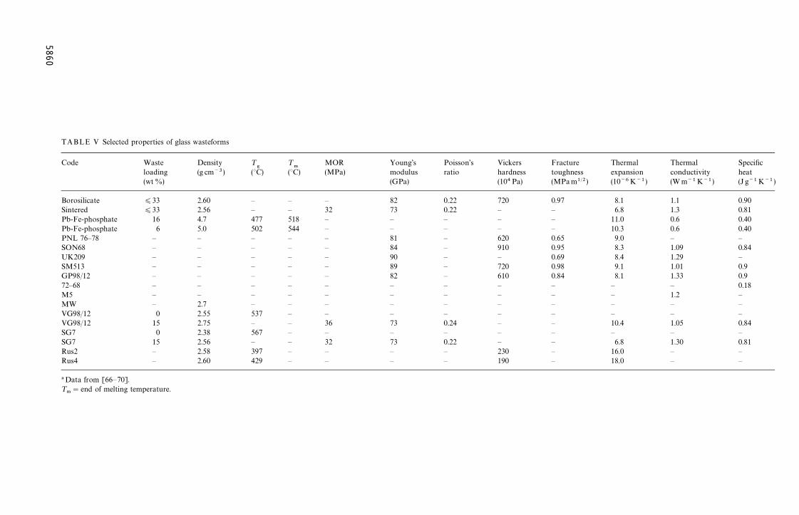
TABLE V Selected
Code g’s Poisson’s Vickers Fracture Thermal Thermal Specificlus ratio hardness toughness expansion conductivity heat) (104Pa) (MPam1@2) (10~6K~1) (Wm~1K~1) (J g~1 K~1 )
Borosilicate 0.22 720 0.97 8.1 1.1 0.90Sintered 0.22 — — 6.8 1.3 0.81Pb-Fe-phosphate — — — 11.0 0.6 0.40Pb-Fe-phosphate — — — 10.3 0.6 0.40PNL 76—78 — 620 0.65 9.0 — —SON68 — 910 0.95 8.3 1.09 0.84UK209 — — 0.69 8.4 1.29 —SM513 — 720 0.98 9.1 1.01 0.9GP98/12 — 610 0.84 8.1 1.33 0.972—68 — — — — — 0.18M5 — — — — 1.2 —MW — — — — — —VG98/12 — — — — — —VG98/12 0.24 — — 10.4 1.05 0.84SG7 — — — — — —SG7 0.22 — — 6.8 1.30 0.81Rus2 — 230 — 16.0 — —Rus4 — 190 — 18.0 — —
!Data from [66—70].¹
."end of melting
58
60
properties of glass wasteforms
Waste Density ¹
'¹
.MOR Youn
loading (g cm~3) (°C) (°C) (MPa) modu(wt %) (GPa
)33 2.60 — — — 82)33 2.56 — — 32 73
16 4.7 477 518 — —6 5.0 502 544 — —
— — — — — 81— — — — — 84— — — — — 90— — — — — 89— — — — — 82— — — — — —— — — — — —— 2.7 — — — —0 2.55 537 — — —
15 2.75 — — 36 730 2.38 567 — — —
15 2.56 — — 32 73— 2.58 397 — — —— 2.60 429 — — —
temperature.
approach by encapsulation in a suitable matrixmaterial.
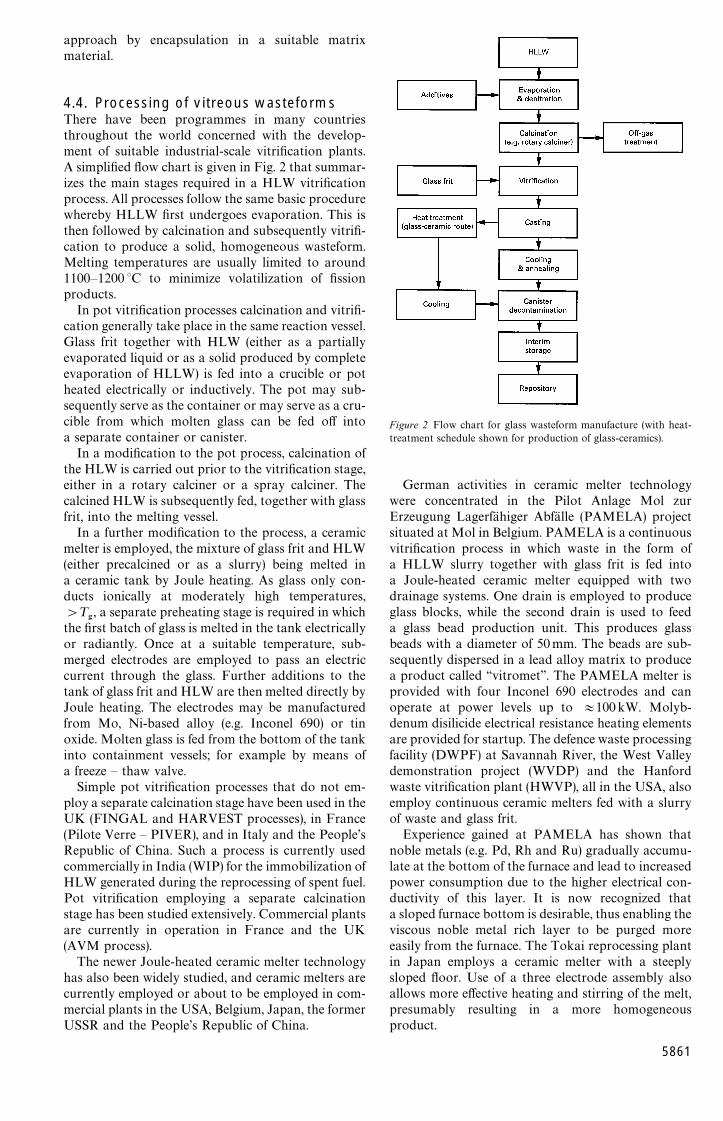
4.4. Processing of vitreous wasteformsThere have been programmes in many countriesthroughout the world concerned with the develop-ment of suitable industrial-scale vitrification plants.A simplified flow chart is given in Fig. 2 that summar-izes the main stages required in a HLW vitrificationprocess. All processes follow the same basic procedurewhereby HLLW first undergoes evaporation. This isthen followed by calcination and subsequently vitrifi-cation to produce a solid, homogeneous wasteform.Melting temperatures are usually limited to around1100—1200 °C to minimize volatilization of fissionproducts.
In pot vitrification processes calcination and vitrifi-cation generally take place in the same reaction vessel.Glass frit together with HLW (either as a partiallyevaporated liquid or as a solid produced by completeevaporation of HLLW) is fed into a crucible or potheated electrically or inductively. The pot may sub-sequently serve as the container or may serve as a cru-cible from which molten glass can be fed off intoa separate container or canister.
In a modification to the pot process, calcination ofthe HLW is carried out prior to the vitrification stage,either in a rotary calciner or a spray calciner. Thecalcined HLW is subsequently fed, together with glassfrit, into the melting vessel.
In a further modification to the process, a ceramicmelter is employed, the mixture of glass frit and HLW(either precalcined or as a slurry) being melted ina ceramic tank by Joule heating. As glass only con-ducts ionically at moderately high temperatures,'¹
', a separate preheating stage is required in which
the first batch of glass is melted in the tank electricallyor radiantly. Once at a suitable temperature, sub-merged electrodes are employed to pass an electriccurrent through the glass. Further additions to thetank of glass frit and HLW are then melted directly byJoule heating. The electrodes may be manufacturedfrom Mo, Ni-based alloy (e.g. Inconel 690) or tinoxide. Molten glass is fed from the bottom of the tankinto containment vessels; for example by means ofa freeze — thaw valve.
Simple pot vitrification processes that do not em-ploy a separate calcination stage have been used in theUK (FINGAL and HARVEST processes), in France(Pilote Verre — PIVER), and in Italy and the People’sRepublic of China. Such a process is currently usedcommercially in India (WIP) for the immobilization ofHLW generated during the reprocessing of spent fuel.Pot vitrification employing a separate calcinationstage has been studied extensively. Commercial plantsare currently in operation in France and the UK(AVM process).
The newer Joule-heated ceramic melter technologyhas also been widely studied, and ceramic melters arecurrently employed or about to be employed in com-mercial plants in the USA, Belgium, Japan, the formerUSSR and the People’s Republic of China.
Figure 2 Flow chart for glass wasteform manufacture (with heat-treatment schedule shown for production of glass-ceramics).
German activities in ceramic melter technologywere concentrated in the Pilot Anlage Mol zurErzeugung Lagerfahiger Abfalle (PAMELA) projectsituated at Mol in Belgium. PAMELA is a continuousvitrification process in which waste in the form ofa HLLW slurry together with glass frit is fed intoa Joule-heated ceramic melter equipped with twodrainage systems. One drain is employed to produceglass blocks, while the second drain is used to feeda glass bead production unit. This produces glassbeads with a diameter of 50mm. The beads are sub-sequently dispersed in a lead alloy matrix to producea product called ‘‘vitromet’’. The PAMELA melter isprovided with four Inconel 690 electrodes and canoperate at power levels up to +100kW. Molyb-denum disilicide electrical resistance heating elementsare provided for startup. The defence waste processingfacility (DWPF) at Savannah River, the West Valleydemonstration project (WVDP) and the Hanfordwaste vitrification plant (HWVP), all in the USA, alsoemploy continuous ceramic melters fed with a slurryof waste and glass frit.
Experience gained at PAMELA has shown thatnoble metals (e.g. Pd, Rh and Ru) gradually accumu-late at the bottom of the furnace and lead to increasedpower consumption due to the higher electrical con-ductivity of this layer. It is now recognized thata sloped furnace bottom is desirable, thus enabling theviscous noble metal rich layer to be purged moreeasily from the furnace. The Tokai reprocessing plantin Japan employs a ceramic melter with a steeplysloped floor. Use of a three electrode assembly alsoallows more effective heating and stirring of the melt,presumably resulting in a more homogeneousproduct.
5861
A very large ceramic melter facility was constructedin the former USSR in the 1980s for vitrification ofphosphate and borosilicate wasteforms. Molybdenumelectrodes were used and the maximum power re-quirement of the melter was around 1.5MW. It wasreported that over an 18 month period this facilityincorporated almost 1 km3 of radioactive solutionsinto phosphate glass.
A high temperature melter has been proposed [79]aimed at increasing the solubility of HLW in borosili-cate glass from around 30 to 45% simply by increasingthe melting temperature. This would offer the advant-age that it would lead to a reduction in the overallvolume of the wasteform and consequently lead tolower disposal costs. The higher temperatures in-volved would, however, require the use of a morecomplex melter design due to the increased volatiliz-ation of a number of waste species, in particular Cs;and this would add to the capital costs of the melter inaddition to increasing the overall running costs. Otherstudies have suggested that HLW concentrations ashigh as 45 wt% can be incorporated into borosilicatewasteforms at temperatures as low as 1100—1150 °C(e.g. [80]).
5. Immobilization as a ceramicwasteform
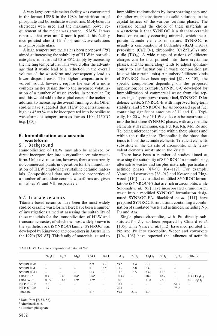
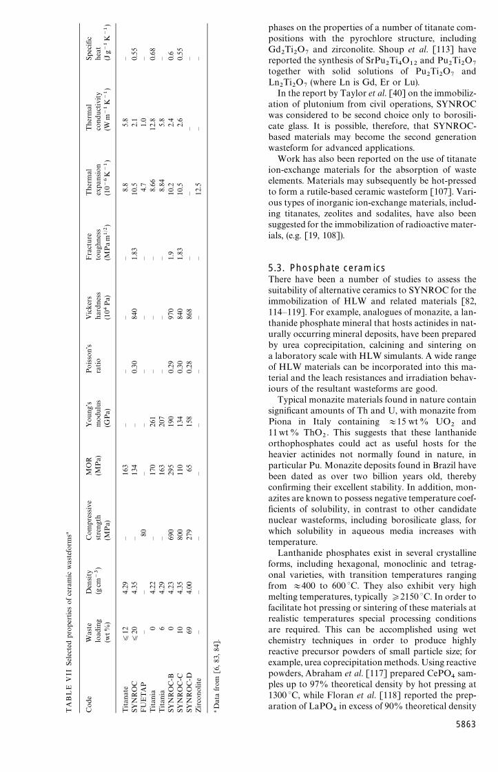
5.1. BackgroundImmobilization of HLW may also be achieved bydirect incorporation into a crystalline ceramic waste-form. Unlike vitrification, however, there are currentlyno commercial plants in operation for the immobiliz-ation of HLW employing crystalline ceramic mater-ials. Compositional data and selected properties ofa number of candidate ceramic wasteforms are givenin Tables VI and VII, respectively.
5.2. Titanate ceramicsTitanate-based ceramics have been the most widelystudied ceramic wasteform. There have been a numberof investigations aimed at assessing the suitability ofthese materials for the immobilization of HLW andtransuranic wastes, of which the most widely known isthe synthetic rock (SYNROC) family. SYNROC wasdeveloped by Ringwood and coworkers in Australia inthe 1970s [85—87]. This family of materials is used to
5862
immobilize radionuclides by incorporating them andthe other waste constituents as solid solutions in thecrystal lattices of the various ceramic phases. Therationale behind the choice of these materials asa wasteform is that SYNROC is a titanate ceramicbased on naturally occurring minerals, which incor-porate actinide elements in nature. SYNROC isusually a combination of hollandite (BaAl
2Ti
2O
6),
perovskite (CaTiO3), zirconolite (CaZrTi
2O
7) and
rutile (TiO2). A wide range of cations of different
charges can be incorporated into these crystallinephases, and the mineralogy tends to adjust spontan-eously to any fluctuations in waste composition (atleast within certain limits). A number of different kindsof SYNROC have been reported [81, 88—103], thespecific composition depending on the proposedapplication; for example, SYNROC-C developed forimmobilization of commercial waste from the rep-rocessing of spent power reactor fuel, SYNROC-D fordefence waste, SYNROC-E with improved long-termstability, and SYNROC-F for unprocessed spent fuelcontaining significant amounts of U and Pu. Typi-cally, 10—20wt % of HLW oxides can be incorporatedinto the first three SYNROC phases, with any metallicelements still remaining, e.g. Pd, Ru, Rh, Mo, Re andTc, being microencapsulated within these phases andwithin the rutile phase. Zirconolite is the phase thattends to host the actinide elements. Trivalent elementssubstitute in the Ca site of zirconolite, while tetra-valent elements substitute in the Zr site.
There have been a number of studies aimed atassessing the suitability of SYNROC for immobilizingalternative wastes and surplus materials, particularlyactinide phases [87—90, 104—112]. For example,Vance and coworkers [88—91] and Kesson and Ring-wood [110] have studied modified SYNROC formu-lations (SYNROC-F) that are rich in zirconolite, whileSolomah et al. [95] have incorporated uranium-richwaste into a modified SYNROC formulation desig-nated SYNROC-FA. Blackford et al. [111] haveprepared SYNROC formulations containing a combi-nation of simulated waste and actinides, including Np,Pu and Am.
Single phase zirconolite, with Pu directly sub-stituted for Zr, has been prepared by Clinard et al.[105], while Vance et al. [112] have incorporated U,Np and Pu into zirconolite. Weber and coworkers[104, 106] have reported the influence of actinide
TABLE VI Ceramic compositional data (wt%)!
Na2O K
2O MgO CaO BaO TiO
2ZrO
2Al
2O
3SiO
2P2O
5Others
SYNROC-B — — — 15.9 7.2 59.5 11.4 6.0 — — —SYNROC-C — — — 11.1 5.5 71.2 6.8 5.4 — — —SYNROC-D — — — 10.3 — 31.8 8.5 33.6 15.8 — —DR-FBR" 0.4 0.4 0.45 0.45 — 0.45 — 78.6 18.7 — 0.45 Fe
2O
3DR-LWR" 0.65 0.65 1.95 1.95 — 0.3 — 71.8 22.3 — 0.3 Fe
2O
3NTP 10—21# 7.3 — — — — 38.4 — — — 54.3 —NTP 60—28# 1.7 — — — — 20.1 — — — 78.2 —Titanate — — — 11.7 — 59.1 27.3 1.9 — — —
!Data from [6, 81, 82]."Aluminosilicate.#Titanium phosphate.
TA
BL
EV
IISel
ecte
dpro
pert
ies
ofce
ram
icw
aste
form
s!
Cod
eW
aste
Den
sity
Com
pre
ssiv
eM
OR
You
ng’
sPoisso
n’s
Vic
kers
Fra
cture
Ther
mal
Ther
mal
Spec
ific
load
ing
(gcm
~3)
stre
ngt
h(M
Pa)
modu
lus
ratio
har
dne
ssto
ugh
nes
sex
pan
sion
conduct
ivity
heat
(wt%
)(M
Pa)
(GPa)
(104
Pa)
(MP
am
1@2)
(10~
6K
~1)
(Wm
~1K
~1)
(Jg~
1K
~1)
Titan
ate
)12
4.29
—16
3—
——
—8.
85.
8—
SYN
RO
C)
204.
35—
134
—0.
3084
01.
8310
.52.
10.
55FU
ETA
P—
—80
——
——
—4.
71.
0—
Titan
ia0
4.22
—17
026
1—
——
8.66
12.8
0.68
Titan
ia6
4.29
—16
320
7—
——
8.84
5.8
—SY
NR
OC
-B0
4.23
690
295
190
0.29
970
1.9
10.2
2.4
0.6
SYN
RO
C-C
104.
3580
011
013
40.
3084
01.
8310
.52.
60.
55SY
NR
OC
-D69
4.00
279
6515
80.
2886
8—
——
—Zirco
nolit
e—
——
——
——
—12
.5—
—
!D
ata
from
[6,83
,84]
.
phases on the properties of a number of titanate com-positions with the pyrochlore structure, includingGd
2Ti
2O
7and zirconolite. Shoup et al. [113] have
reported the synthesis of SrPu2Ti
4O
12and Pu
2Ti
2O
7together with solid solutions of Pu
2Ti
2O
7and
Ln2Ti
2O
7(where Ln is Gd, Er or Lu).
In the report by Taylor et al. [40] on the immobiliz-ation of plutonium from civil operations, SYNROCwas considered to be second choice only to borosili-cate glass. It is possible, therefore, that SYNROC-based materials may become the second generationwasteform for advanced applications.
Work has also been reported on the use of titanateion-exchange materials for the absorption of wasteelements. Materials may subsequently be hot-pressedto form a rutile-based ceramic wasteform [107]. Vari-ous types of inorganic ion-exchange materials, includ-ing titanates, zeolites and sodalites, have also beensuggested for the immobilization of radioactive mater-ials, (e.g. [19, 108]).
5.3. Phosphate ceramicsThere have been a number of studies to assess thesuitability of alternative ceramics to SYNROC for theimmobilization of HLW and related materials [82,114—119]. For example, analogues of monazite, a lan-thanide phosphate mineral that hosts actinides in nat-urally occurring mineral deposits, have been preparedby urea coprecipitation, calcining and sintering ona laboratory scale with HLW simulants. A wide rangeof HLW materials can be incorporated into this ma-terial and the leach resistances and irradiation behav-iours of the resultant wasteforms are good.
Typical monazite materials found in nature containsignificant amounts of Th and U, with monazite fromPiona in Italy containing +15 wt% UO
2and
11wt% ThO2. This suggests that these lanthanide
orthophosphates could act as useful hosts for theheavier actinides not normally found in nature, inparticular Pu. Monazite deposits found in Brazil havebeen dated as over two billion years old, therebyconfirming their excellent stability. In addition, mon-azites are known to possess negative temperature coef-ficients of solubility, in contrast to other candidatenuclear wasteforms, including borosilicate glass, forwhich solubility in aqueous media increases withtemperature.
Lanthanide phosphates exist in several crystallineforms, including hexagonal, monoclinic and tetrag-onal varieties, with transition temperatures rangingfrom +400 to 600 °C. They also exhibit very highmelting temperatures, typically *2150 °C. In order tofacilitate hot pressing or sintering of these materials atrealistic temperatures special processing conditionsare required. This can be accomplished using wetchemistry techniques in order to produce highlyreactive precursor powders of small particle size; forexample, urea coprecipitation methods. Using reactivepowders, Abraham et al. [117] prepared CePO
4sam-
ples up to 97% theoretical density by hot pressing at1300 °C, while Floran et al. [118] reported the prep-aration of LaPO
4in excess of 90% theoretical density
5863
by hot pressing or sintering at 1100 °C. Dense samplesof lanthanide phosphates loaded with up to 50%simulated wastes have also been prepared successfullyby cold pressing and sintering at temperatures as lowas 900 °C [117].
Other phosphates investigated (e.g. [8, 115, 116,120]) have included a single phase sodium zirconiumphosphate (NZP) with the composition NaZr
2(PO
4)3.
The structure of NZP contains three types of crystal-lographic sites and exhibits great compositional flex-ibility. Waste loadings up to 20wt% have beenincorporated into this structure using sol—gel andsintering techniques while maintaining a single phasematerial. For loadings '20% it has been observedthat a two-phase material is formed, with monazite asthe second phase. Work has also been reported onsubstitution of Ti for Zr to yield a sodium titaniumphosphate (NTP), which under suitable conditionscan accommodate up to 60% waste loadings [82].
Work has also been reported on the direct synthesisof Th and U phosphates employing a wet chemistryand sintering route [119, 120]. It was noted thatTh
3(PO
4)4
was produced as expected, but that theanalogous U compound was not formed; insteada mixed valence compound was formed that was iden-tified as U(UO
2)(PO
4)2.
5.4. Alternative ceramicsSome of the earliest work on the immobilization ofHLW in ceramics, which predated the SYNROC con-cept, produced materials described as ‘‘supercalcine’’,which were generally based on calcium silicate [121].Early work also assessed the feasibility of utilizingnatural clays for the immobilization of HLW [122].A number of alternative mineral phases, includingperovskite, pyrochlore, monazite and nepheline havesince been examined for specific HLW compositions,and high HLW loadings and densities achieved usinghot isostatic pressing techniques [9].
Recently crichtonite, SrM21
O38
(M"Ti, Fe, Mg,Mn, Zn, Cr, Al, Zr, Hf, U, V, Nb, Sn, Cu, Ni), has beenproposed as a host for both actinide and fission prod-uct phases [123]. A wasteform consisting of cubiczirconia, Fe
3O
4and BaZrO
3crystalline phases has
also recently been proposed [124] for immobilizingpurex wastes containing high concentrations of Feand Zr. The material can be made by a wet chemistryroute to produce precursor powders. After calcinationthese powders may be cold pressed and sintered. Lan-thanum zirconate, La
2Zr
2O
7, together with a number
of alternative pyrochlore phases have been suggestedas prospective hosts both for actinide and lanthaniderich phases [125, 126]. Mixed La
2Zr
2O
7—2CeO
2. 2ZrO
2phases have also been prepared [125] by cold pressingand sintering at 1400 °C in air or reducingatmosphere. It was noted that actinide elements couldbe accommodated in either 3` or 4` lattice sitesdepending on the reducing conditions employed.
There are few details at present on alternatives toSYNROC as crystalline ceramic hosts for the immo-bilization of uranium or plutonium from dismantlednuclear weapons or from civil operations. In one
5864
study, however, Ewing et al. have proposed the use ofzircon [127]. Zircon, ZrSiO
4, is a stable, naturally
occurring mineral that contains radioactive U and Thin nature. Zircon is commonly employed in the datingof mineral samples (from the U/Pb ratio present) andconsequently its mineralogy has been studied inten-sively. It has been noted that Pu can substitute directlyfor Zr and the pure end-compound PuSiO
4has been
successfully synthesized. Several processing opera-tions have been demonstrated on a laboratory scalefor the preparation of zircon and Pu substitutedzircon, including sol—gel and hot pressing. Other com-plex rare earth silicates have also been investigated asactinide host phases [106], including Ca
2Nd
8(SiO
4)6O
2.
5.5. Processing of ceramic wasteformsThe most widely studied ceramic material has beenSYNROC [6], and there have been many studiesaimed at the development of processing routes for themanufacture of SYNROC and related wasteforms.
Early work on SYNROC processing relied onpreparing precursor materials by conventional or tra-ditional powder methods; for example, mechanicalgrinding and mixing. Later work has concentrated onthe use of wet chemistry processes; for example, use ofhydroxide and alkoxide precursors, and by sol—gelmethods. These wet chemistry routes have been shownto be superior and more reliable and efficient than theconventional methods in achieving well reacted andhomogeneous end products. In addition, use of highlyreactive precursor powders allows lower sintering orhot pressing temperatures to be used.
For example, a method developed at SandiaNational Laboratory (SNL) in the USA [101], em-ploys reactive precursors with high specific surfaceareas. This technology was subsequently transferredand used as the reference process for precursor mater-ials employed in the Australian SYNROC demonstra-tion plant. In the later hydroxide process, methanolwas added to a mixture of titanium isopropoxide,zirconium n-butoxide and aluminium sec-butoxide inthe appropriate proportions [6]. This alkoxide feed-stock was then hydrolysed and the resultant precursorwas mixed with HLW in the form of a slurry. At theAtomic Energy Authority (AEA), Harwell, UK,a sol—gel process has also been used in which nitrate-stabilized titania and zirconia sols have been mixedwith dispersible alumina together with barium andcaesium nitrate solutions [96]. The resultant mixturewas subsequently spray dried to produce a free-flow-ing powder.
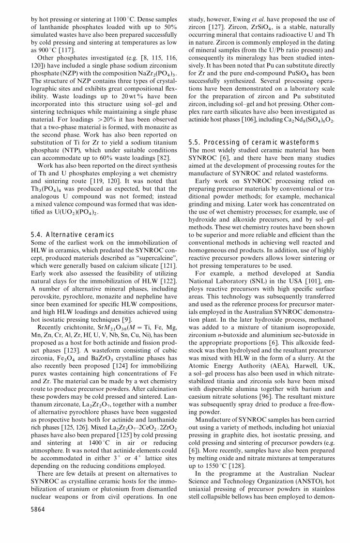
Manufacture of SYNROC samples has been carriedout using a variety of methods, including hot uniaxialpressing in graphite dies, hot isostatic pressing, andcold pressing and sintering of precursor powders (e.g.[6]). More recently, samples have also been preparedby melting oxide and nitrate mixtures at temperaturesup to 1550 °C [128].
In the programme at the Australian NuclearScience and Technology Organization (ANSTO), hotuniaxial pressing of precursor powders in stainlessstell collapsible bellows has been employed to demon-

Figure 3 Flow chart for SYNROC manufacture.
strate the fabrication of SYNROC on a commercialscale. A simplified flow chart showing the generalstages in hot pressing of SYNROC is shown in Fig. 3(it should be noted, however, that SYNROC has not,to date, been employed for the commercial immobiliz-ation of active HLW). In this operation the precursoris mixed with simulated HLLW to form a slurry that issubsequently fed to a rotary calciner where it is driedand calcined in a reducing atmosphere. The calcinedproduct is then mixed with 2 wt% titanium metalpowder to act as an oxygen getter before being fed intothe bellows. After filling, a plug is welded over the feedhole and the bellows evacuated. The closed bellowsis then cold pressed to approximately two-thirds itsoriginal height before loading into a hot press andpressing at +1150 °C and 14—21 MPa pressure. Theprocess has gradually been scaled up to produce sam-ples 436mm in diameter. In an active commercial op-eration it is likely that a number of compressed bellowswould be loaded into suitable canisters for disposal.
A comparison has been made of SYNROC pre-pared both by hot pressing and cold pressing andsintering routes [129]. It was concluded that, as longas an appropriate binder burn-out stage was incorpor-ated, the sintering route gave good results comparableto those achieved by hot pressing.
6. Immobilization as a glass-ceramicwasteform
6.1. BackgroundMany ceramic phases are known to possess superiorchemical durabilities to borosilicate glasses under
typical repository conditions. Ceramics, however, aregenerally multiphase systems containing many minorphases in addition to the major crystalline phases, andit can be difficult to predict long term behaviour inrepository environments. In addition, the technologyassociated with the manufacture of crystalline ceram-ics is, in general, more complex than that associatedwith the production of glasses (particularly with therequirement for remote handling facilities in a nuclearenvironment). It has, therefore, been proposed thatglass-ceramics may offer a useful compromise betweenglasses and ceramics, being easier and less expensiveto prepare than conventional ceramics, but offeringhigher durability than glasses.
Glass-ceramics are defined as polycrystalline ce-ramic materials prepared by the controlled bulk crys-tallization of suitable glasses [130]. Crystallization ofconventional glasses normally occurs by the nuclea-tion of crystals at external surfaces. This crystall-ization behaviour generally gives rise to a coarsemicrostructure with large anisotropic crystals thatgrow inwards from the surfaces of the glass. Suchmaterials are usually weak mechanically. The successof the glass-ceramic process in producing mechan-ically strong, fine-grained polycrystalline ceramic ma-terials depends on inducing a high crystal nuleationdensity within the bulk of the glass by providing a verylarge number of internal heterogeneities from whichthe major crystalline phases can form and grow. Thiscan be achieved in practice by the use of specificnucleating agents that are added to the glass batch.Nucleating agents act either by inducing the glass tophase separate on a very fine scale, or by formingsmall crystallites (of the nucleating phase itself or ofsome compound formed by reaction with the constitu-ents in the glass). In either case, many small heterogen-eities are produced, onto which the major crystallinephases can nucleate and grow [130, 131].
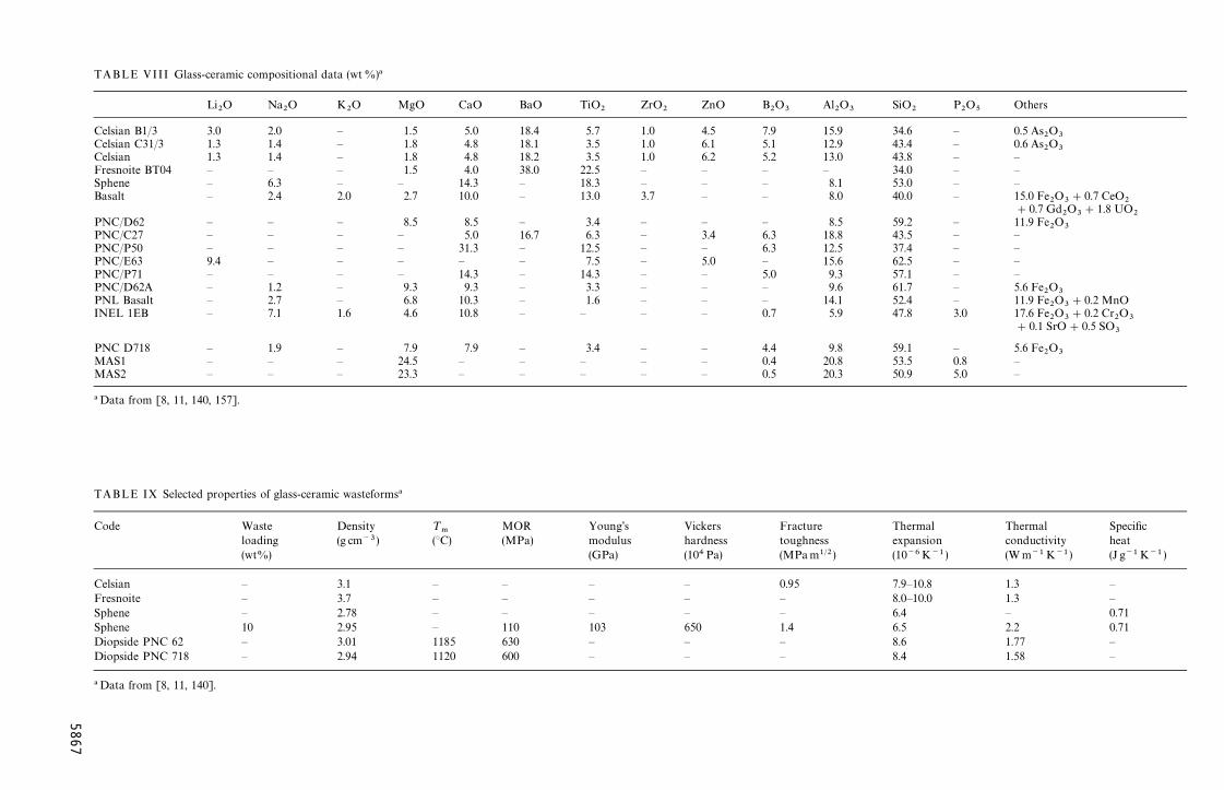
Proposed modifications of the vitrification processfor the immobilization of HLW include use of aglass-ceramic as the host for the waste materials. Vit-reous blanks may be produced employing standardvitrification procedures. The glass blank can then besubjected to an additional heat treatment schedule inorder to crystallize the glass into the glass-ceramicform.
In addition to offering ease of manufacture relativeto conventional ceramics, coupled with higher dura-bility than glasses, a number of further potentialadvantages have been associated with the use of glass-ceramics as HLW wasteforms. These include higherthermal stabilities than borosilicate glass, superiormechanical properties, and an ability to tailor many oftheir properties to meet the challenges of specificapplications. In addition, glass-ceramics are moretolerant of variations in waste composition than arecorresponding crystalline ceramics prepared by con-ventional routes. Glass-ceramics do, however, requirean additional heat treatment relative to conventionalglasses, thus leading to greater processing complexity,as discussed more fully later.
A number of different glass-ceramic families havebeen proposed for the immobilization of HLW
5865
[132—157]. Much of the work is based on pioneeringstudies at the Hahn-Meitner Institute (HMI) in Berlin,the Whiteshell Nuclear Research Establishment(WNRE) in Canada, the Battelle Pacific NorthwestLaboratory (PNL) in the USA, and the Power Reac-tor and Nuclear Fuel Development Corporation(PNC) in conjunction with the Nippon Electric GlassCo. in Japan. Compositional data and selected prop-erties of the glass-ceramics considered for the immo-bilization of HLW are summarized in Tables VIII andIX, respectively. Work in this area is summarizedbelow.
6.2. Barium aluminosilicate glass-ceramicsA number of modified borosilicate based waste glasscompositions containing simulated waste were cry-stallized in the pioneering HMI studies to yield aselection of specific crystalline phases, including glass-ceramics with celsian (BaAl
2Si
2O
8) as the major phase
[154]. Other phases present in these celsian glass-ceramics included pyrochlore (RE
2Ti
2O
7; RE"rare
earth), scheelite (BaMoO4), pollucite (CsAlSi
2O
6) and
molybdenum-nosean [Na8Al
6MoO
4(SiO
4)6]. It was
noted that the pyrochlore phase acted as a host foractinides and Sr, while the host for Cs and Rb waspollucite. Noble metal fission products were observedto precipitate out as small metallic droplets. Meltingtemperatures in the range 1175—1250 °C were em-ployed to produce the precursor glasses. The glasseswere subsequently nucleated and crystallized at+620 ° and 800 °C, respectively.
Radiation damage of celsian glass-ceramics hasbeen measured directly by doping with Pu or Cm[8, 11]. Mechanical properties have also been studied.The leaching characteristics of the celsian glass-ceram-ics have been measured in a number of comprehensivestudies (see [8, 11]) and have been noted to be compa-rable to the borosilicate glasses. The leach rates are infact higher than many other glass-ceramics due to therelatively high boron content. As there is no signifi-cant advantage in the durability of celsian glass-cer-amics over borosilicate glasses, additional work in thisarea has subsequently been limited.
6.3. Barium titanium silicate glass-ceramicsStudies at HMI have also included the productionof fresnoite (BaTiSi
2O
8) glass-ceramics [154]. The
aim of this work was to produce a glass-ceramicwasteform lower in boron than the celsian materialsand consequently of greater durability. Additionalphases in these glass-ceramics included Ba-priderite(BaFe
2Ti
6O
16), pyrochlore and scheelite. It was noted
that the scheelite phase acted as host to Ba and Sr,while Cs remained in the residual glassy phase.A melting temperature of 1200 °C was employed toproduce the precursor glasses. The glasses were sub-sequently nucleated at temperatures of the orderof 700 °C and crystallized in the range 900—960 °C.Although these materials were found to exhibit im-proved mechanical properties relative to borosilicateglasses, unfortunately their durabilities were not
5866
enhanced. Consequently, additional work on thesematerials has also been limited.
6.4. Calcium magnesium silicateglass-ceramics
Glass-ceramics containing diopside (CaMgSi2O
6) as
the major crystalline phase have been produced atHMI [154]. Glass-ceramics based on the calciummagnesium silicate system containing diopside,powellite (CaMoO
4) and perovskite have also been
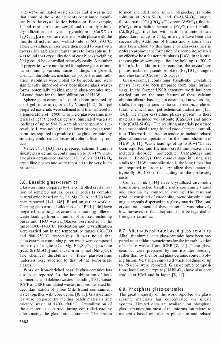
reported by workers in Japan at the Nippon ElectricGlass Co. [148]. Simulated waste loadings of up to30 wt% could be achieved using these materials. Theglasses were melted at 1300 °C. Crystallization wascarried out at temperatures in the range 800—1100 °C,usually during controlled cooling of the melt, withoutthe inclusion of a separate nucleation stage. Thismethod of processing eliminated the requirement fora separate additional heat treatment schedule, therebysimplifying the manufacturing process. A bulk diop-side glass-ceramic sample has been prepared witha diameter of 30 cm and weighing 65 kg.
Relatively low leach rates have been noted for someof these glass-ceramics, making them useful potentialcandidates for the immobilization of HLW.
6.5. Calcium titanium silicateglass-ceramics
Work at HMI has also included the preparation ofperovskite (CaTiO
3) based glass-ceramics; again this
work was later abandoned due to durability consider-ations.
On the other hand, glass-ceramics from the calcuimtitanium silicate system with sphene (CaTiSiO
5) as the
major crystalline phase have been extensively studiedby Hayward and coworkers at WNRE as a candidatefor the immobilization of potential CANDU wastes[8, 11, 135, 137, 138, 141]. The rationale behind thechoice of these materials lies in the fact that sphene isa common constituent of many types of rocks, andcalculations have shown that sphene is stable inthe saline environment likely to be found within theCanadian Shield.
In the work reported by Hayward, compositionswithin the Na
2O—Al
2O
3—CaO—TiO
2—SiO
2system
were chosen for detailed study because these glasseswere thermally stable and were therefore more recep-tive to controlled bulk crystallization. In addition, theresidual aluminosilicate glassy phases were likely to bechemically durable. Numerous compositions wereexamined in this work. Glasses were melted in thetemperature range 1250—1450 °C, and nucleated at650—1050 °C and crystallized at 950—1050 °C for vary-ing periods of time. It was noted that sphene was themajor, or in fact the only, crystalline phase formed,together with a residual aluminosilicate glass matrixphase. It was observed, however, that crystallizationoccurred in an uncontrolled manner by nucleation atexternal surfaces and internal heterogeneities, and thisresulted in a coarse microstructure. Glass-ceramicswere subsequently prepared containing up to
ZnO B2O
3Al
2O
3SiO
2P2O
5Others
4.5 7.9 15.9 34.6 — 0.5 As2O
36.1 5.1 12.9 43.4 — 0.6 As
2O
36.2 5.2 13.0 43.8 — —— — — 34.0 — —— — 8.1 53.0 — —— — 8.0 40.0 — 15.0 Fe
2O
3#0.7 CeO
2#0.7 Gd
2O
3#1.8 UO
2— — 8.5 59.2 — 11.9 Fe
2O
33.4 6.3 18.8 43.5 — —— 6.3 12.5 37.4 — —5.0 — 15.6 62.5 — —— 5.0 9.3 57.1 — —— — 9.6 61.7 — 5.6 Fe
2O
3— — 14.1 52.4 — 11.9 Fe
2O
3#0.2 MnO
— 0.7 5.9 47.8 3.0 17.6 Fe2O
3#0.2 Cr
2O
3#0.1 SrO#0.5 SO
3
— 4.4 9.8 59.1 — 5.6 Fe2O
3— 0.4 20.8 53.5 0.8 —— 0.5 20.3 50.9 5.0 —
kers Fracture Thermal Thermal Specificdness toughness expansion conductivity heat4Pa) (MPam1@2) (10~6K~1) (W m~1 K~1) (J g~1K~1 )
0.95 7.9—10.8 1.3 —— 8.0—10.0 1.3 —— 6.4 — 0.711.4 6.5 2.2 0.71— 8.6 1.77 —— 8.4 1.58 —
TABLE VIII Glass-ceramic compositional data (wt%)!
Li2O Na
2O K
2O MgO CaO BaO TiO
2ZrO
2
Celsian B1/3 3.0 2.0 — 1.5 5.0 18.4 5.7 1.0Celsian C31/3 1.3 1.4 — 1.8 4.8 18.1 3.5 1.0Celsian 1.3 1.4 — 1.8 4.8 18.2 3.5 1.0Fresnoite BT04 — — — 1.5 4.0 38.0 22.5 —Sphene — 6.3 — — 14.3 — 18.3 —Basalt — 2.4 2.0 2.7 10.0 — 13.0 3.7
PNC/D62 — — — 8.5 8.5 — 3.4 —PNC/C27 — — — — 5.0 16.7 6.3 —PNC/P50 — — — — 31.3 — 12.5 —PNC/E63 9.4 — — — — — 7.5 —PNC/P71 — — — — 14.3 — 14.3 —PNC/D62A — 1.2 — 9.3 9.3 — 3.3 —PNL Basalt — 2.7 — 6.8 10.3 — 1.6 —INEL 1EB — 7.1 1.6 4.6 10.8 — — —
PNC D718 — 1.9 — 7.9 7.9 — 3.4 —MAS1 — — — 24.5 — — — —MAS2 — — — 23.3 — — — —
!Data from [8, 11, 140, 157].
TABLE IX Selected properties of glass-ceramic wasteforms!
Code Waste Density ¹.
MOR Young’s Vicloading (g cm~3) (°C) (MPa) modulus har(wt%) (GPa) (10
Celsian — 3.1 — — — —Fresnoite — 3.7 — — — —Sphene — 2.78 — — — —Sphene 10 2.95 — 110 103 650Diopside PNC 62 — 3.01 1185 630 — —Diopside PNC 718 — 2.94 1120 600 — —
!Data from [8, 11, 140].
586
7
+25wt % simulated waste oxides and it was notedthat some of the waste elements contributed signifi-cantly to the crystallization behaviour. For example,U and rare earth ions were found to catalyse bulkcrystallization to yield pyrochlore [Ca(RE,U)Ti
2O
7$x], a mixed rare-earth/U oxide phase with the
fluorite structure, and wollastonite at 800—900 °C.These crystalline phases were then noted to react withexcess silica at higher temperatures to form sphene. Itwas found that crystallization of cast blocks weighing20 kg could be controlled relatively easily. A numberof properties were monitored for sphene glass-ceram-ics containing various waste loadings. In general,chemical durabilities, mechanical properties and radi-ation stabilities were noted to be good, and weresignificantly improved over borosilicate glass waste-forms, potentially making sphene glass-ceramics use-ful candidates for the immobilization of HLW.
Sphene glass-ceramics have also been prepared bya sol—gel route, as reported by Vance [142]. Sol—gelprepared materials were calcined and then sintered ata temperature of )900 °C to yield glass-ceramic ma-terials of near theoretical density. Simulated wastes atloadings of up to 5wt % were also incorporated suc-cessfully. It was noted that the lower processing tem-peratures required to produce these glass-ceramics bysintering could reduce losses of volatile fission prod-ucts.
Vance et al. [63] have prepared calcium titaniumsilicate glass-ceramics containing up to 50wt % UO
2.
The glass-ceramics contained CaUTi2O
7and UTi
2O
6crystalline phases and were reported to be very leachresistant.
6.6. Basaltic glass-ceramicsGlass-ceramics prepared by the controlled crystalliza-tion of remelted natural basaltic rocks (a complexnatural oxide based on Si, Ca, Mg, Fe, Al and Ti) havebeen reported [141, 146]. Based on earlier work atCorning glass works, Lokken et al. of PNL [146] haveprepared basaltic glass-ceramics containing differentwaste loadings from a number of sources, includingpurex and TRU wastes. Glasses were melted in therange 1300—1400 °C. Nucleation and crystallizationwere carried out in the temperature ranges 670—700and 900—950 °C, respectively. It was noted thatglass-ceramics containing purex waste were composedprimarily of augite [(Ca, Mg, Fe)
2Si
2O
6], powellite
[(Ca, Sr) MoO4] and nickel-iron spinel (NiFe
2O
4).
The chemical durabilities of these glass-ceramicmaterials were superior to that of the borosilicateglasses.
Work on iron-enriched basaltic glass-ceramics hasalso been reported for the immobilization of bothcommercial and defence wastes, including TRU waste,ICPP and SRP simulated wastes, and zeolites used fordecontamination of Three Mile Island containmentwater together with core debris [8, 11]. Glass-ceram-ics were prepared by melting batch materials andcalcined waste at 1400—1500 °C. Crystallization ofthese materials occurred during controlled coolingafter casting the glass into containers. The phases
5868
formed included iron spinel, plagioclase (a solidsolution of NaAlSi
3O
8and CaAl
2Si
2O
8), augite,
fluoroapatite [Ca5(PO
4)3F], zircon (ZrSiO
4), fluorite
(CaF2), cristobalite, hematite (Fe
2O
3) and mullite
(Al6Si
2O
13), together with residial aluminosilicate
glass. Samples up to 75 kg in weight have been castsuccessfully. Additions of titania and zirconia havealso been added to this family of glass-ceramics inorder to promote the formation of zirconolite, which isan effective host for actinide phases [143]. In this case,the cast glasses were crystallized by holding at 1200 °Cfor 16 h. In addition to zirconolite, the crystallizedphases included pseudobrookite (Fe
2TiO
5), augite
and chevkinite (Ce4Fe
2Ti
3Si
4O
22).
Glass-ceramics containing basalt-like crystallinephases have also been prepared from blast furnaceslags. In the former USSR extensive work has beencarried out on the manufacture of these calciumaluminosilicate based glass-ceramics, known as slagsitalls, for applications in the construction, architec-tural, chemical and petrochemical industries [155,156]. The major crystalline phases present in thesematerials included wollastonite (CaSiO
3) and anor-
thite (CaAl2Si
2O
8). The resulting materials possessed
high mechanical strengths and good chemical durabil-ities. This work has been extended to include relatedglass-ceramic compositions for the immobilization ofHLW [8, 11]. Waste loadings of up to 50wt% havebeen reported, and the main crystalline phases haveincluded diopside, montecellite (CaMgSiO
4) and
fayalite (Fe2SiO
4). One disadvantage in using slag
sitalls for HLW immobilization is the long times thatare required in order to crystallize these materials(typically 50—100h), this adding to the processingcosts.
Conley et al. [144] have crystallized zirconolitefrom iron-enriched basaltic melts containing titaniaand zirconia by controlled cooling. The resultantproduct consisted of zirconolite, pseudobrookite andaugite crystals dispersed in a glassy matrix. The totalcrystalline content of these materials was relativelylow, however, so that they could not be regarded astrue glass-ceramics.
6.7. Alternative silicate based glass-ceramicsAlkali titanium silicate glass-ceramics have been pre-pared as candidate wasteforms for the immobilizationof defence wastes from ICPP [8, 11]. These glass-ceramics were prepared by hot isostatic pressing,rather than by the normal glass-ceramic route involv-ing fusion. Very high simulated waste loadings of upto 75wt % were reported. Glass-ceramic composi-tions based on eucryptite (LiAlSi
2O
6) have also been
studied at HMI and in Japan [8, 11].
6.8. Phosphate glass-ceramicsThe great majority of the work reported on glass-ceramic materials has concentrated on silicatesystems. Limited data are available on phosphateglass-ceramics, but most of the information relates tomaterials based on calcium phosphate and related
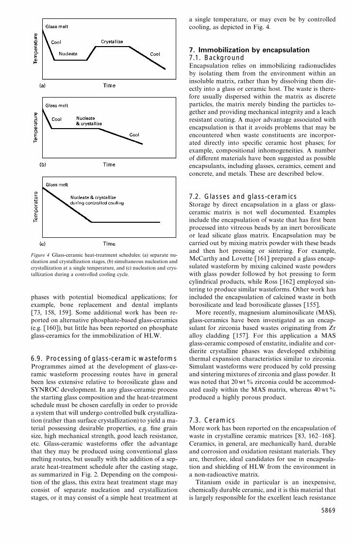
Figure 4 Glass-ceramic heat-treatment schedules: (a) separate nu-cleation and crystallization stages, (b) simultaneous nucleation andcrystallization at a single temperature, and (c) nucleation and crys-tallization during a controlled cooling cycle.
phases with potential biomedical applications; forexample, bone replacement and dental implants[73, 158, 159]. Some additional work has been re-ported on alternative phosphate-based glass-ceramics(e.g. [160]), but little has been reported on phosphateglass-ceramics for the immobilization of HLW.
6.9. Processing of glass-ceramic wasteformsProgrammes aimed at the development of glass-ce-ramic wasteform processing routes have in generalbeen less extensive relative to borosilicate glass andSYNROC development. In any glass-ceramic processthe starting glass composition and the heat-treatmentschedule must be chosen carefully in order to providea system that will undergo controlled bulk crystalliza-tion (rather than surface crystallization) to yield a ma-terial possessing desirable properties, e.g. fine grainsize, high mechanical strength, good leach resistance,etc. Glass-ceramic wasteforms offer the advantagethat they may be produced using conventional glassmelting routes, but usually with the addition of a sep-arate heat-treatment schedule after the casting stage,as summarized in Fig. 2. Depending on the composi-tion of the glass, this extra heat treatment stage mayconsist of separate nucleation and crystallizationstages, or it may consist of a simple heat treatment at
a single temperature, or may even be by controlledcooling, as depicted in Fig. 4.
7. Immobilization by encapsulation7.1. BackgroundEncapsulation relies on immobilizing radionuclidesby isolating them from the environment within aninsoluble matrix, rather than by dissolving them dir-ectly into a glass or ceramic host. The waste is there-fore usually dispersed within the matrix as discreteparticles, the matrix merely binding the particles to-gether and providing mechanical integrity and a leachresistant coating. A major advantage associated withencapsulation is that it avoids problems that may beencountered when waste constituents are incorpor-ated directly into specific ceramic host phases; forexample, compositional inhomogeneities. A numberof different materials have been suggested as possibleencapsulants, including glasses, ceramics, cement andconcrete, and metals. These are described below.
7.2. Glasses and glass-ceramicsStorage by direct encapsulation in a glass or glass-ceramic matrix is not well documented. Examplesinclude the encapsulation of waste that has first beenprocessed into vitreous beads by an inert borosilicateor lead silicate glass matrix. Encapsulation may becarried out by mixing matrix powder with these beadsand then hot pressing or sintering. For example,McCarthy and Lovette [161] prepared a glass encap-sulated wasteform by mixing calcined waste powderswith glass powder followed by hot pressing to formcylindrical products, while Ross [162] employed sin-tering to produce similar wasteforms. Other work hasincluded the encapsulation of calcined waste in bothborosilicate and lead borosilicate glasses [155].
More recently, magnesium aluminosilicate (MAS),glass-ceramics have been investigated as an encap-sulant for zirconia based wastes originating from Zralloy cladding [157]. For this application a MASglass-ceramic composed of enstatite, indialite and cor-dierite crystalline phases was developed exhibitingthermal expansion characteristics similar to zirconia.Simulant wasteforms were produced by cold pressingand sintering mixtures of zirconia and glass powder. Itwas noted that 20wt% zirconia could be accommod-ated easily within the MAS matrix, whereas 40wt%produced a highly porous product.
7.3. CeramicsMore work has been reported on the encapsulation ofwaste in crystalline ceramic matrices [83, 162—168].Ceramics, in general, are mechanically hard, durableand corrosion and oxidation resistant materials. Theyare, therefore, ideal candidates for use in encapsula-tion and shielding of HLW from the environment ina non-radioactive matrix.
Titanium oxide in particular is an inexpensive,chemically durable ceramic, and it is this material thatis largely responsible for the excellent leach resistance
5869
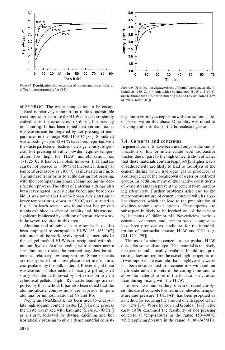
Figure 5 Densification characteristics of titania (anatase powder) atdifferent temperatures (after [83]).
of SYNROC. The waste composition to be encap-sulated is relatively unimportant (unless undesirablereactions occur) because the HLW particles are simplyembedded in the ceramic matrix during hot pressingor sintering. It has been noted that certain titaniawasteforms can be prepared by hot pressing at tem-peratures in the range 950—1150 °C [83]. Simulatedwaste loadings up to 12wt % have been reported, withthe waste particles embedded heterogeneously. In gen-eral, hot pressing of rutile powder requires temper-atures too high for HLW immobilization, i.e.'1325 °C. It has been noted, however, that anatasecan be hot pressed to '99% of theoretical density attemperatures as low as 1100 °C, as illustrated in Fig. 5.The anatase transforms to rutile during hot pressing,with the accompanying phase change aiding the den-sification process. The effect of sintering aids has alsobeen investigated, in particular boron and boron ox-ide. It was noted that 1 wt % boron aids sintering atlower temperatures, down to 950 °C, as illustrated inFig. 6. In leach tests it was found that hot pressedtitania exhibited excellent durability and this was notsignificantly affected by addition of boron. More workis, however, required in this area.
Alumina and aluminosilicate ceramics have alsobeen employed to encapsulate HLW [83, 163—167]with much of the work involving sol—gel methods. Inthe sol—gel method HLW is coprecipitated with alu-minium hydroxide after seeding with submicrometresize alumina particles; the material may then be sin-tered at relatively low temperatures. Some elementsare incorporated into host phases that are, in turn,encapsulated by the bulk material. Processing of thesewasteforms has also included mixing a pH-adjustedslurry of material, followed by hot extrusion to yieldcylindrical pellets. High TRU waste loadings are re-ported by this method. It has also been noted that thealuminosilicate compositions are superior to purealumina for immobilization of Cs and Rb.
Nepheline (NaAlSiO4), has been used to encapsu-
late high sodium content wastes [21]. In one processthe waste was mixed with kaolinite [Si
2Al
2O
5(OH)
4]
as a slurry, followed by drying, calcining and hotisostatically pressing to give a dense material consist-
5870
Figure 6 Densification characteristics of titania-based materials. (a)titania at 1150 °C, (b) titania with 6% simulated HLW at 1150 °C,and (c) titania with 1% boron sintering aid and 6% simulated HLWat 950 °C (after [83]).
ing almost entirely as nepheline with the radionuclidesdispersed within this phase. Durability was noted tobe comparable to that of the borosilicate glasses.
7.4. Cements and concretesIn general, cements have been used only for the immo-bilization of low or intermediate level radioactivewastes, due in part to the high concentration of waterthat these materials contain (e.g. [169]). Higher levelsof radioactivity are likely to lead to radiolysis of thecement during which hydrogen gas is produced asa consequence of the breakdown of water or hydroxylgroups. In addition, many of the inactive constituentsof waste streams can prevent the cement from harden-ing adequately. Further problems arise due to themicroporous nature of cement, coupled with its alka-line character, which can lead to the precipitation ofalkaline-insoluble waste species. These species aresubsequently likely to be leached out of the cementby leachants of different pH. Nevertheless, variouscements, concretes and cement-based compositeshave been proposed as candidates for the immobil-ization of intermediate waste, HLW and TRU (e.g.[84, 170—179]).
The use of a simple cement to encapsulate HLWdoes offer some advantages. The material is relativelyinexpensive and is readily available. In addition, pro-cessing does not require the use of high temperatures.It was reported, for example, that a highly acidic wastehas been encapsulated in a cement mix with sodiumhydroxide added to retard the curing time and toallow the material to set in the final canister, ratherthan during mixing with the HLW.
In order to minimize the problem of radiohydroly-sis, the use of concrete formed under elevated temper-ature and pressure (FUETAP) has been proposed asa method for reducing the amount of entrapped waterto +2% [84]. Work by Roy and Goulda [177] in theearly 1970s examined the feasibility of hot pressingconcrete at temperatures in the range 150—400 °Cwhile applying pressure in the range +180—345MPa.

Figure 7 Flow chart for the manufacture of FUETAP (formedunder elevated temperature and pressure) concrete.
A number of simulated radioactive waste composi-tions were employed in these studies. Subsequentwork at the Oak Ridge National Laboratory in theUSA used lower temperatures and pressures to con-solidate materials with very low residual porosity suc-cessfully. This work led Moore [176] to considerFUETAP concrete for the immobilization of HLW.When HLW was used, the thermal power of the wastehelped to cure the concrete, which in these studieswas kept under a pressure of only 0.1—4.0 MPa at100—250 °C. In principle the concrete mix can betailored to a certain degree for specific waste streams,and to promote different properties, e.g. good mechan-ical strength, high density and high thermal conduct-ivity. The processing of FUETAP concrete is unfortu-nately a relatively complex procedure (particularlywhen considering remote handling facilities), as illus-trated by the flow chart shown in Fig. 7. Most of theresearch into FUETAP was curtailed in the early1980s following the decision to use borosilicate glassas the preferred wasteform at the Savannah RiverPlant.
7.5. Multibarrier approachThe principle behind the use of multibarriers is the‘‘Russian doll’’ approach, with specific materials serv-ing specific purposes in the containment of the HLW.This approach is therefore related to that of encap-sulation, but in general relies on the provision ofadditional barriers [180—184]. For example, Treat[185] reported the encapsulation of waste immobi-
lized in calcium silicate pellets in a lead matrix. Theaim of this approach was to improve the leach resist-ance and impact strength of the resulting wasteform.In related studies immobilized waste pellets have beencoated with pyrolytic graphite, before encapsulating ina metal matrix, in order to improve the leach resist-ance further [186, 188]. Application of other coatingshas also been reported, including alumina, titania,silica, silicon carbide, chromium silicide and chro-mium oxide, together with a variety of metals includ-ing Ni, Fe and Mo. Dual coatings of pyrolytic graph-ite and alumina have also been reported [189]. Metalmatrices have included Pb-based alloys (e.g. Pb—Sb,Al, Sn), Al-based alloys (e.g. Al—Si, Cu, Ti), and Cu.
In one variation of the commercial PAMELA pro-cess glass beads containing HLW are produced bypassing molten glass through nozzles. The beads aresubsequently fed into a container and infiltrated withmolten lead alloy to produce a composite wasteform(‘‘vitromet’’). The beads, with a diameter of +50 mm,occupy up to 66% of the total volume. Increasedthermal conductivity of the wasteform leading tolower waste temperatures is one of the most importantadvantages of this product.
Cermets are related composite wasteforms in whichradionuclides in the form of small oxide or silicateparticles +1 lm in size are dispersed in a metalmatrix. Waste loadings of up to around 30% havebeen reported [9].
The multibarrier approach can also refer to the useof canisters and containers for storing nuclear mater-ials. Each canister will normally be composed ofa number of materials, usually metallic alloys, eachwith a specific purpose; for example, to impart cor-rosion resistance, radiation shielding, mechanicalstrength, etc. The use of ceramic canisters has alsobeen proposed [190].
8. Stabilities and durabilities ofwasteforms
8.1. Thermal and mechanical stabilitiesThe mechanical properties of some candidate nuclearwasteform materials have been reasonably well char-acterized. Data are available for flexural strength(both uniaxial and biaxial), compressive strength,elastic moduli, mechanical hardness and fracturetoughness [191—200]. Thermal data include thermalexpansion, thermal conductivity and specific heat. Re-lated properties have also been monitored, includingthermal shock resistance (e.g. [191]).
Data have also been collected for a number of wasteglasses that have enabled TTT or CCT curves to beconstructed [5, 12, 201, 202]. Use of these curvesmakes it possible to determine whether or not glassstability is likely to present a problem for specificmaterials, cooling regimes or the storage conditionslikely to be encountered in a repository. Fig. 8 showsa schematic TTT curve for a glass. This shows that ifthe cooling rate of the glass is too low, the coolingcurve will intersect the TTT curve and crystals will beformed. The greater the area intersected, the greaterthe proportion of crystalline phases in the final
5871
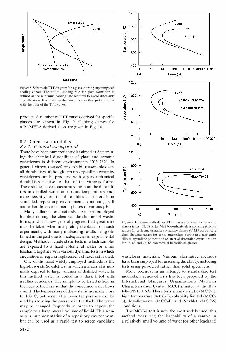
Figure 8 Schematic TTT diagram for a glass showing superimposedcooling curves. The critical cooling rate for glass formation isdefined as the minimum cooling rate required to avoid detectablecrystallization. It is given by the cooling curve that just coincideswith the nose of the TTT curve.
product. A number of TTT curves derived for specificglasses are shown in Fig. 9. Cooling curves fora PAMELA derived glass are given in Fig. 10.
8.2. Chemical durability8.2.1. General backgroundThere have been numerous studies aimed at determin-ing the chemical durabilities of glass and ceramicwasteforms in different environments [203—252]. Ingeneral, vitreous wasteforms exhibit reasonable over-all durabilities, although certain crystalline ceramicswasteforms can be produced with superior chemicaldurabilities relative to that of the vitreous forms.These studies have concentrated both on the durabili-ties in distilled water at various temperatures and,more recently, on the durabilities of materials insimulated repository environments containing saltand other dissolved mineral phases of various pH.
Many different test methods have been employedfor determining the chemical durabilities of waste-forms, and it is now generally agreed that great caremust be taken when interpreting the data from suchexperiments, with many misleading results being ob-tained in the past due to inadequacies in experimentaldesign. Methods include static tests in which samplesare exposed to a fixed volume of water or otherleachant, together with various dynamic tests in whichcirculation or regular replacement of leachant is used.
One of the most widely employed methods is thehigh-flow-rate Soxhlet test in which a material is nor-mally exposed to large volumes of distilled water. Inthis method water is boiled in a flask fitted witha reflux condenser. The sample to be tested is held inthe neck of the flask so that the condensed water flowsover it. The temperature of the water is normally closeto 100 °C, but water at a lower temperature can beused by reducing the pressure in the flask. The watermay be changed frequently in order to expose thesample to a large overall volume of liquid. This scen-ario is unrepresentative of a repository environment,but can be used as a rapid test to screen candidate
5872
Figure 9 Experimentally derived TTT curves for a number of wasteglasses (after [12, 18]) : (a) M22 borosilicate glass showing stabilityranges for ceria and enstatite crystalline phases; (b) M5 borosilicateglass showing ranges for ceria, magnesium borate and rare earthsilicate crystalline phases; and (c) start of detectable crystallizationfor 72—68 and 76—68 commercial borosilicate glasses.
wasteform materials. Various alternative methodshave been employed for assessing durability, includingtests using powdered rather than solid specimens.
More recently, in an attempt to standardize testmethods, a series of tests has been proposed by theInternational Standards Organization’s MaterialsCharacterization Centre (MCC) situated at the Bat-telle PNL, USA. These tests simulate static (MCC-1),high temperature (MCC-2), solubility limited (MCC-3), low-flow-rate (MCC-4) and Soxhlet (MCC-5)conditions.
The MCC-1 test is now the most widely used, thismethod measuring the leachability of a sample ina relatively small volume of water (or other leachant)
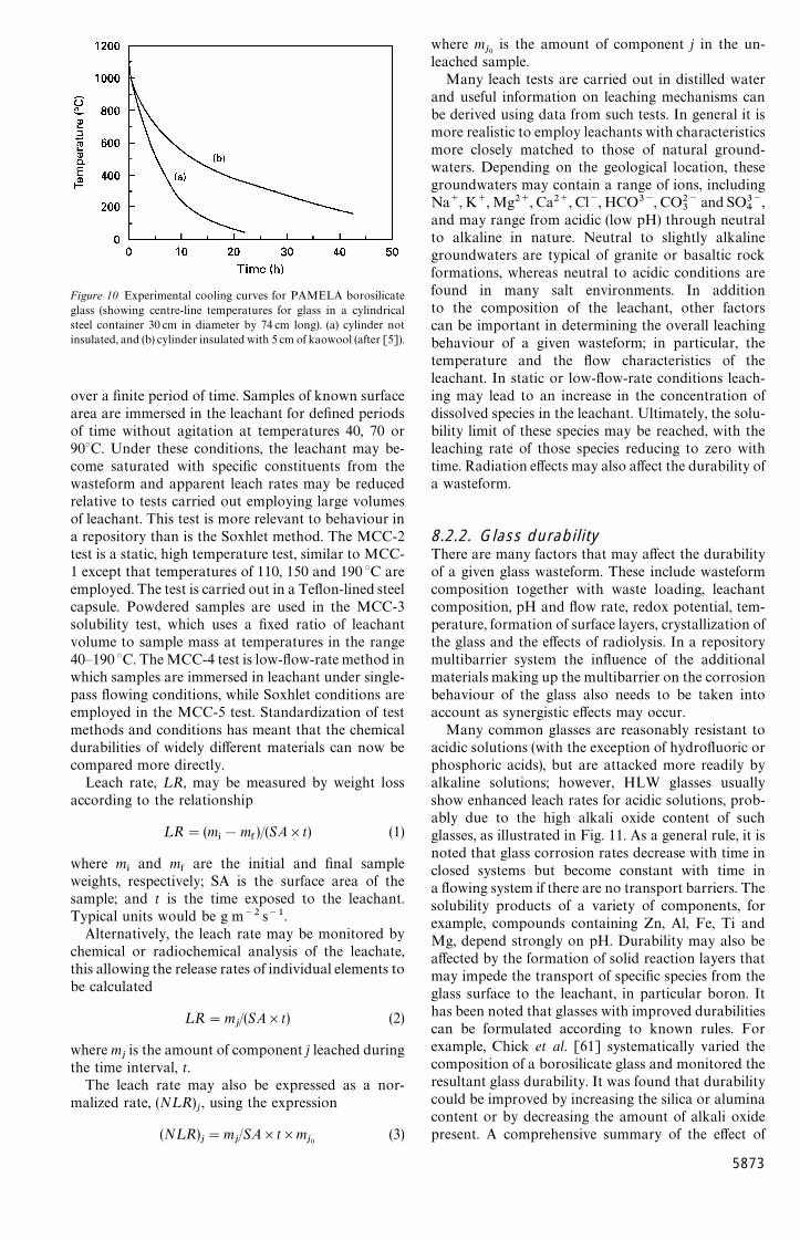
Figure 10 Experimental cooling curves for PAMELA borosilicateglass (showing centre-line temperatures for glass in a cylindricalsteel container 30 cm in diameter by 74 cm long). (a) cylinder notinsulated, and (b) cylinder insulated with 5 cm of kaowool (after [5]).
over a finite period of time. Samples of known surfacearea are immersed in the leachant for defined periodsof time without agitation at temperatures 40, 70 or90°C. Under these conditions, the leachant may be-come saturated with specific constituents from thewasteform and apparent leach rates may be reducedrelative to tests carried out employing large volumesof leachant. This test is more relevant to behaviour ina repository than is the Soxhlet method. The MCC-2test is a static, high temperature test, similar to MCC-1 except that temperatures of 110, 150 and 190 °C areemployed. The test is carried out in a Teflon-lined steelcapsule. Powdered samples are used in the MCC-3solubility test, which uses a fixed ratio of leachantvolume to sample mass at temperatures in the range40—190 °C. The MCC-4 test is low-flow-rate method inwhich samples are immersed in leachant under single-pass flowing conditions, while Soxhlet conditions areemployed in the MCC-5 test. Standardization of testmethods and conditions has meant that the chemicaldurabilities of widely different materials can now becompared more directly.
Leach rate, ¸R, may be measured by weight lossaccording to the relationship
¸R"(m*!m
&)/(SA]t) (1)
where m*
and m&
are the initial and final sampleweights, respectively; SA is the surface area of thesample; and t is the time exposed to the leachant.Typical units would be g m~2 s~1.
Alternatively, the leach rate may be monitored bychemical or radiochemical analysis of the leachate,this allowing the release rates of individual elements tobe calculated
¸R"mj/(SA]t) (2)
where mjis the amount of component j leached during
the time interval, t.The leach rate may also be expressed as a nor-
malized rate, (N¸R)j, using the expression
(N¸R)j"m
j/SA]t]m
j0(3)
where mj0
is the amount of component j in the un-leached sample.
Many leach tests are carried out in distilled waterand useful information on leaching mechanisms canbe derived using data from such tests. In general it ismore realistic to employ leachants with characteristicsmore closely matched to those of natural ground-waters. Depending on the geological location, thesegroundwaters may contain a range of ions, includingNa`, K , Mg2`, Ca2`, Cl~, HCO3~, CO2~
3and SO3~
4,
and may range from acidic (low pH) through neutralto alkaline in nature. Neutral to slightly alkalinegroundwaters are typical of granite or basaltic rockformations, whereas neutral to acidic conditions arefound in many salt environments. In additionto the composition of the leachant, other factorscan be important in determining the overall leachingbehaviour of a given wasteform; in particular, thetemperature and the flow characteristics of theleachant. In static or low-flow-rate conditions leach-ing may lead to an increase in the concentration ofdissolved species in the leachant. Ultimately, the solu-bility limit of these species may be reached, with theleaching rate of those species reducing to zero withtime. Radiation effects may also affect the durability ofa wasteform.
8.2.2. Glass durabilityThere are many factors that may affect the durabilityof a given glass wasteform. These include wasteformcomposition together with waste loading, leachantcomposition, pH and flow rate, redox potential, tem-perature, formation of surface layers, crystallization ofthe glass and the effects of radiolysis. In a repositorymultibarrier system the influence of the additionalmaterials making up the multibarrier on the corrosionbehaviour of the glass also needs to be taken intoaccount as synergistic effects may occur.
Many common glasses are reasonably resistant toacidic solutions (with the exception of hydrofluoric orphosphoric acids), but are attacked more readily byalkaline solutions; however, HLW glasses usuallyshow enhanced leach rates for acidic solutions, prob-ably due to the high alkali oxide content of suchglasses, as illustrated in Fig. 11. As a general rule, it isnoted that glass corrosion rates decrease with time inclosed systems but become constant with time ina flowing system if there are no transport barriers. Thesolubility products of a variety of components, forexample, compounds containing Zn, Al, Fe, Ti andMg, depend strongly on pH. Durability may also beaffected by the formation of solid reaction layers thatmay impede the transport of specific species from theglass surface to the leachant, in particular boron. Ithas been noted that glasses with improved durabilitiescan be formulated according to known rules. Forexample, Chick et al. [61] systematically varied thecomposition of a borosilicate glass and monitored theresultant glass durability. It was found that durabilitycould be improved by increasing the silica or aluminacontent or by decreasing the amount of alkali oxidepresent. A comprehensive summary of the effect of
5873
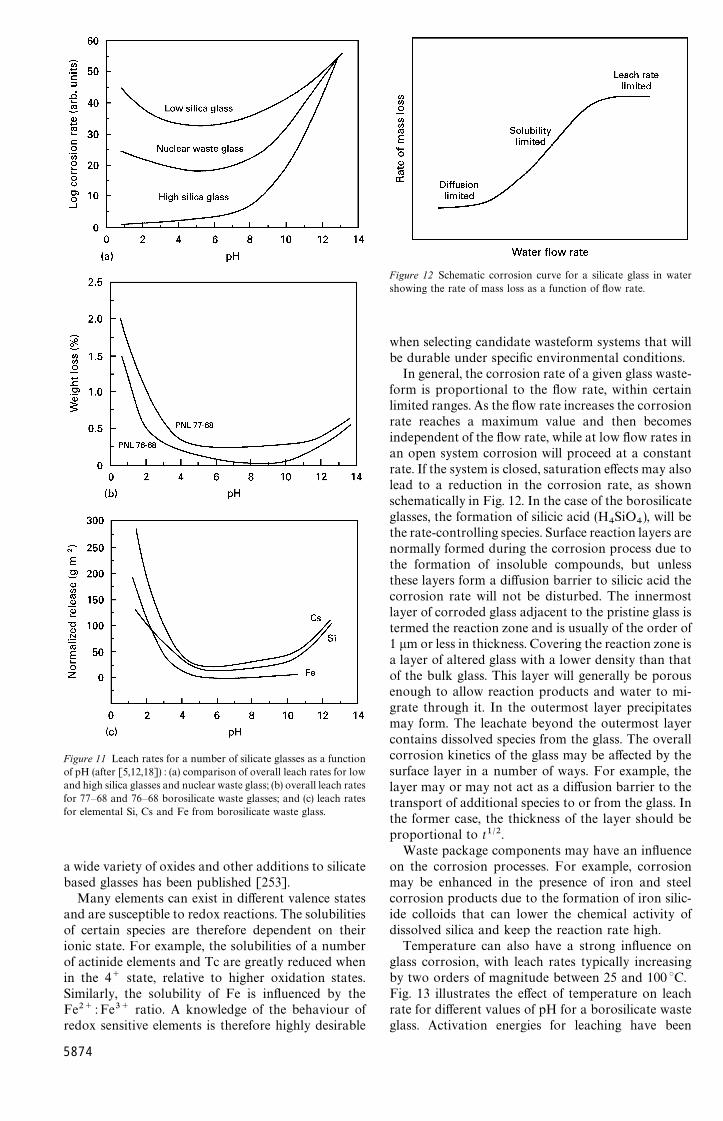
Figure 11 Leach rates for a number of silicate glasses as a functionof pH (after [5,12,18]) : (a) comparison of overall leach rates for lowand high silica glasses and nuclear waste glass; (b) overall leach ratesfor 77—68 and 76—68 borosilicate waste glasses; and (c) leach ratesfor elemental Si, Cs and Fe from borosilicate waste glass.
a wide variety of oxides and other additions to silicatebased glasses has been published [253].
Many elements can exist in different valence statesand are susceptible to redox reactions. The solubilitiesof certain species are therefore dependent on theirionic state. For example, the solubilities of a numberof actinide elements and Tc are greatly reduced whenin the 4` state, relative to higher oxidation states.Similarly, the solubility of Fe is influenced by theFe2` : Fe3` ratio. A knowledge of the behaviour ofredox sensitive elements is therefore highly desirable
5874
Figure 12 Schematic corrosion curve for a silicate glass in watershowing the rate of mass loss as a function of flow rate.
when selecting candidate wasteform systems that willbe durable under specific environmental conditions.
In general, the corrosion rate of a given glass waste-form is proportional to the flow rate, within certainlimited ranges. As the flow rate increases the corrosionrate reaches a maximum value and then becomesindependent of the flow rate, while at low flow rates inan open system corrosion will proceed at a constantrate. If the system is closed, saturation effects may alsolead to a reduction in the corrosion rate, as shownschematically in Fig. 12. In the case of the borosilicateglasses, the formation of silicic acid (H
4SiO
4), will be
the rate-controlling species. Surface reaction layers arenormally formed during the corrosion process due tothe formation of insoluble compounds, but unlessthese layers form a diffusion barrier to silicic acid thecorrosion rate will not be disturbed. The innermostlayer of corroded glass adjacent to the pristine glass istermed the reaction zone and is usually of the order of1 lm or less in thickness. Covering the reaction zone isa layer of altered glass with a lower density than thatof the bulk glass. This layer will generally be porousenough to allow reaction products and water to mi-grate through it. In the outermost layer precipitatesmay form. The leachate beyond the outermost layercontains dissolved species from the glass. The overallcorrosion kinetics of the glass may be affected by thesurface layer in a number of ways. For example, thelayer may or may not act as a diffusion barrier to thetransport of additional species to or from the glass. Inthe former case, the thickness of the layer should beproportional to t1@2.
Waste package components may have an influenceon the corrosion processes. For example, corrosionmay be enhanced in the presence of iron and steelcorrosion products due to the formation of iron silic-ide colloids that can lower the chemical activity ofdissolved silica and keep the reaction rate high.
Temperature can also have a strong influence onglass corrosion, with leach rates typically increasingby two orders of magnitude between 25 and 100 °C.Fig. 13 illustrates the effect of temperature on leachrate for different values of pH for a borosilicate wasteglass. Activation energies for leaching have been
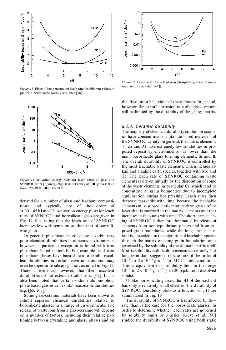
Figure 13 Effect of temperature on leach rate for different values ofpH for a borosilicate waste glass (after [18]).
Figure 14 Activation energy plots for leach rates of glass andSYNROC (after [6] and [228]) : (h) Cs From glass, (j) glass, (s) Csfrom SYNROC, (d) SYNROC.
derived for a number of glass and leachant composi-tions, and typically are of the order of+30—145 kJ mol~1. Activation energy plots for leachrates of SYNROC and borosilicate glass are given inFig. 14, illustrating that the leach rate of SYNROCincreases less with temperature than that of borosili-cate glass.
In general, phosphate based glasses exhibit verypoor chemical durabilities in aqueous environments;however, a particular exception is found with ironphosphate based materials. For example, lead ironphosphate glasses have been shown to exhibit excel-lent durabilities in certain environments, and mayeven be superior to silicate glasses, as noted in Fig. 15.There is evidence, however, that their excellentdurabilities do not extend to salt brines [67]. It hasalso been noted that certain sodium aluminophos-phate based glasses can exhibit reasonable durabilities(e.g. [65, 203]).
Some glass-ceramic materials have been shown toexhibit superior chemical durabilities relative toborosilicate glasses in a range of environments. Therelease of waste ions from a glass-ceramic will dependon a number of factors, including their relative par-tioning between crystalline and glassy phases and on
Figure 15 Leach rates for a lead iron phosphate glass containingsimulated waste (after [67]).
the dissolution behaviour of these phases. In general,however, the overall corrosion rate of a glass-ceramicwill be limited by the durability of the glassy matrix.
8.2.3. Ceramic durabilityThe majority of chemical durability studies on ceram-ics have concentrated on titanate-based materials ofthe SYNROC variety. In general, the matrix elements,Ti, Zr and Al have extremely low solubilities in pro-posed repository environments, far lower than themain borosilicate glass forming elements, Si and B.The overall durability of SYNROC is controlled bythe most leachable waste elements, which include al-kali and alkaline earth species, together with Mo andTc. The leach rate of SYNROC containing wasteelements is driven initially by the dissolution of someof the waste elements, in particular Cs, which tend toconcentrate at grain boundaries due to incompleteequilibration during hot pressing. Leach rates thendecrease markedly with time, because the leachableelements must subsequently migrate through a surfacelayer that is enriched in the matrix elements and thatincreases in thickness with time. The short term leach-ing of SYNROC is therefore dominated by release ofelements from non-equilibrium phases and from ex-posed grain boundaries, while the long term behav-iour is dependent on the migration of leachable speciesthrough the matrix or along grain boundaries, or isgoverned by the solubility of the titanate matrix itself.Matrix solubility is difficult to measure accurately, butlong term data suggest a release rate of the order of10~4 to 2]10~3 g m~2 for MCC-1 test conditions.This is equivalent to a solubility limit in the range10~3 to 2]10~2 gm~3 (1 to 20 p.p.b. total dissolvedsolids).
Unlike borosilicate glasses, the pH of the leachanthas only a relatively small effect on the durability ofSYNROC. Durability plots as a function of pH aresummarized in Fig. 16.
The durability of SYNROC is less affected by flowrate than is the case for the borosilicate glasses. Inorder to determine whether leach rates are governedby solubility limits or kinetics, Reeve et al. [90]studied the durability of SYNROC using both static
5875
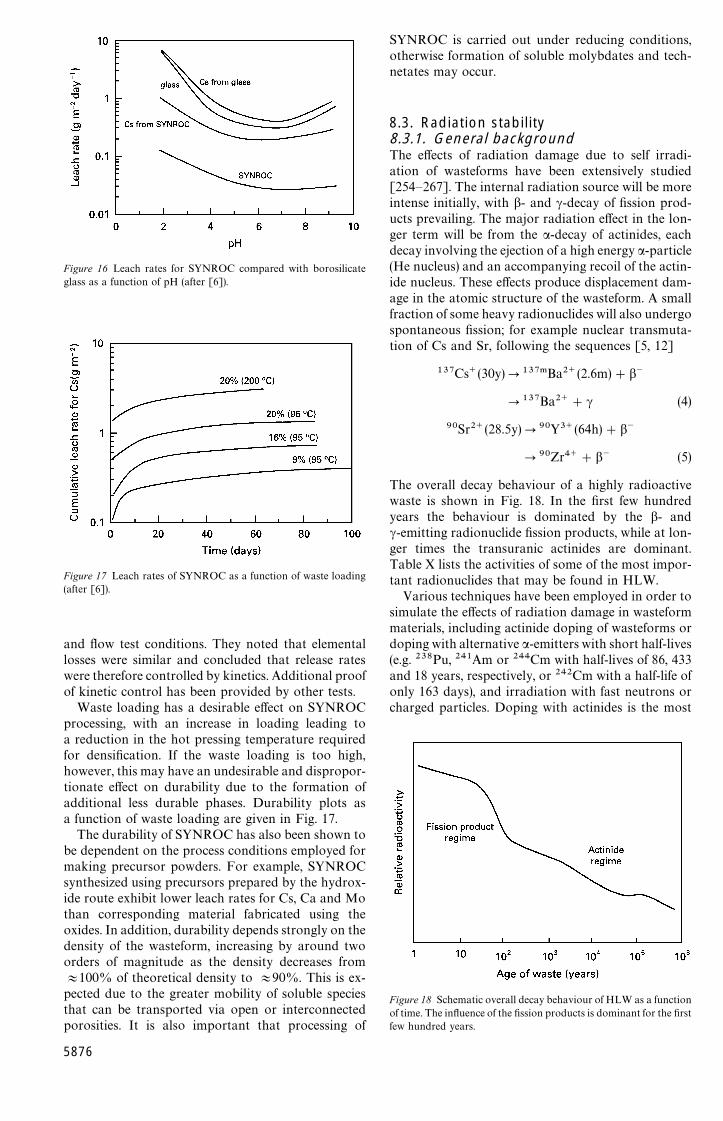
Figure 16 Leach rates for SYNROC compared with borosilicateglass as a function of pH (after [6]).
Figure 17 Leach rates of SYNROC as a function of waste loading(after [6]).
and flow test conditions. They noted that elementallosses were similar and concluded that release rateswere therefore controlled by kinetics. Additional proofof kinetic control has been provided by other tests.
Waste loading has a desirable effect on SYNROCprocessing, with an increase in loading leading toa reduction in the hot pressing temperature requiredfor densification. If the waste loading is too high,however, this may have an undesirable and dispropor-tionate effect on durability due to the formation ofadditional less durable phases. Durability plots asa function of waste loading are given in Fig. 17.
The durability of SYNROC has also been shown tobe dependent on the process conditions employed formaking precursor powders. For example, SYNROCsynthesized using precursors prepared by the hydrox-ide route exhibit lower leach rates for Cs, Ca and Mothan corresponding material fabricated using theoxides. In addition, durability depends strongly on thedensity of the wasteform, increasing by around twoorders of magnitude as the density decreases from+100% of theoretical density to +90%. This is ex-pected due to the greater mobility of soluble speciesthat can be transported via open or interconnectedporosities. It is also important that processing of
5876
Figure 18 Schematic overall decay behaviour of HLW as a functionof time. The influence of the fission products is dominant for the firstfew hundred years.
SYNROC is carried out under reducing conditions,otherwise formation of soluble molybdates and tech-netates may occur.
8.3. Radiation stability8.3.1. General backgroundThe effects of radiation damage due to self irradi-ation of wasteforms have been extensively studied[254—267]. The internal radiation source will be moreintense initially, with b- and c-decay of fission prod-ucts prevailing. The major radiation effect in the lon-ger term will be from the a-decay of actinides, eachdecay involving the ejection of a high energy a-particle(He nucleus) and an accompanying recoil of the actin-ide nucleus. These effects produce displacement dam-age in the atomic structure of the wasteform. A smallfraction of some heavy radionuclides will also undergospontaneous fission; for example nuclear transmuta-tion of Cs and Sr, following the sequences [5, 12]
137Cs (30y)P137.Ba2 (2.6m)#b~
P137Ba2 #c (4)
90Sr2 (28.5y)P90Y3 (64h)#b~
P90Zr4 #b~ (5)
The overall decay behaviour of a highly radioactivewaste is shown in Fig. 18. In the first few hundredyears the behaviour is dominated by the b- andc-emitting radionuclide fission products, while at lon-ger times the transuranic actinides are dominant.Table X lists the activities of some of the most impor-tant radionuclides that may be found in HLW.
Various techniques have been employed in order tosimulate the effects of radiation damage in wasteformmaterials, including actinide doping of wasteforms ordoping with alternative a-emitters with short half-lives(e.g. 238Pu, 241Am or 244Cm with half-lives of 86, 433and 18 years, respectively, or 242Cm with a half-life ofonly 163 days), and irradiation with fast neutrons orcharged particles. Doping with actinides is the most

TABLE X Activities of principal fission products and actinides inHLW as a function of storage time!
Species Activity (GBq g~1)
(4 years) (50 years) (500 years)
Fission products134Cs 5.9 0.000001 3 —137Cs 19.0 6.6 0.0002190Sr 14.0 4.6 0.00007144Ce 2.2 — —147Pm 3.3 0.000016 —151Sm 0.12 0.085 0.0024152Eu 0.001 0.000071 —154Eu 0.61 0.083 0.0003155Eu 0.14 0.0029 —93Zr 0.000 19 0.00019 0.0001999Tc 0.0016 0.0016 0.0016106Ru 5.2 — —107Pd 0.000 012 0.000012 0.000012126Sn 0.000 12 0.00012 0.00012
ActinidesNp 0.000 03 0.00003 0.00003Pu 0.0014 0.0016 0.0008Am 0.07 0.06 0.03Cm 0.004 0.001 0.00006
!From [12].
realistic method, it being possible to accumulatedamage in a few years or less that is equivalent toseveral hundreds or thousands of years for real waste.Radiation damage can also be simulated to a greateror lesser extent by irradiation with charged particles,e.g. electrons, a-particles, heavy ions, etc. Althoughnot as realistic as the actinide doping method, thistechnique does offer the advantage that the irradiatedsimultants do not become radioactive and thereforecan be handled directly.
8.3.2. Glass stabilityIn the case of glasses, radiation induced density vari-ations, *q, may be observed, the overall effect beingdependent on the radiation dose received and thecomposition of the glass. Values for *q generally donot exceed$1% and density changes tend to saturateafter a dose of +1025 am~3 has been received, asnoted in Fig. 19. Stored energy also increases withincreasing radiation dose reaching saturation at sim-ilar doses to density. Stored energy has been studiedextensively to determine whether a sudden releaseof energy might occur that would lead to a rise intemperature sufficient to result in crystallizationand cracking of a wasteform. Structural changes ofcrystalline phases that form within HLW glasses canoccur; for example, crystalline phases such asCa
3Gd
7(SiO
4)5(PO
4)2
and gadolinium titanate havebeen observed. Radiation induced density changes inglass are not yet fully understood, but experimentalevidence suggests that the sign of the density change isdependent on the chemical composition of the glass. Itis known that the density changes can be annealed outof glass, with some recovery taking place even at roomtemperature.
Each a-decay reaction generates one He atom whenthe highly energetic a-particle comes to rest in the
Figure 19 Density change of a number of waste glasses doped with244Cm as a function of dose (after [5]).
glass and captures two electrons. The accumulation ofHe is proportional to the a-dose and may lead toswelling or cracking of the glass. In addition, theformation of He bubbles provides nucleation centreswithin the glass and may lead to uncontrolled crystal-lization if the repository temperature is high enough.This would subsequently introduce undesirableinternal stresses that could promote cracking of thewasteform and lead to higher leach rates. In general,experimental data suggest that the He generated ina glass remains in solid solution, rather than formingdiscrete bubbles or diffusing out of the glass. It is likelythat only a very small fraction of generated He will bereleased during storage, unless the temperature is ab-normally high. The solubility of He in a HLWborosilicate glass (PNL 72—68), for example, has beenfound to be 1.5]1022 atomsm~3.
It may be concluded that, in practice, radiationeffects in glass do not seem to be particularly detri-mental to the longer term integrity or chemicaldurabilities of glasses, at least over the time scales sofar examined.
8.3.3. Ceramic stabilitySimilar effects are observed in crystalline ceramicwasteforms, but in this case the crystalline structure ofthe material is gradually destroyed, with the formationof amorphous (metamict) phases. This can lead tolarger volume changes than associated with glasses,and may lead to some cracking with time.
The a-decay damage of SYNROC is confined al-most exclusively to the perovskite and zirconolitephases that host the actinides. It has been noted thatnatural zirconolite retains a monoclinic crystal struc-ture up to doses of the order of 4.4]1024 a m~3. Atincreased doses, up to 3]1025 a m~3, the structureforms a mixture of crystalline and amorphous do-mains, while at higher doses, '1026 a m~3, the struc-ture becomes both X-ray and electron amorphous.It appears that the chemical durability of naturalzirconolite is not adversely affected by radiationdamage.
5877
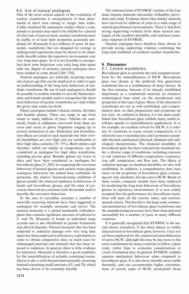
8.4. Use of natural analoguesOne of the most critical aspects of the evaluation ofnuclear wasteforms is extrapolation of data deter-mined in short term testing to longer time scales.Unlike standard life assessment studies where a com-ponent or product may need to be reliable for a periodof a few tens of years at most, nuclear wasteforms mustbe stable, or at least their properties accurately pre-dicted, for thousands if not millions of years. In par-ticular, wasteforms that are designed for storage inunderground repositories must be shown to be chem-ically durable within the repository environment oververy long time spans. As it is not possible to extrapo-late short term behaviour over such long time spanswith any degree of certainty natural analogues havebeen studied in some detail [268—270].
Natural analogues are naturally occurring mater-ials of great age that can be employed in order to gainan understanding of the long term behaviour of syn-thetic wasteforms. By use of such analogues it shouldbe possible to confirm whether or not the thermodyn-amic and kinetic models used to extrapolate the shortterm behaviour of nuclear wasteforms are valid withinthe given time scales involved.
Glassy analogues include volcanic tektites, rhyolitesand basaltic glasses. These can range in age fromrecent to many millions of years. Tektites are com-monly found in sediments recovered from deep seacores and occur as glassy fragments ranging up toseveral centimetres in size. Hydration and devitrifica-tion effects are noted in such materials but their over-all durabilities are very high and are attributable totheir high silica contents (70—75%). Both tektites andrhyolites, which are similar in composition, can beconsidered as analogues for high silica wasteforms,including porous glass. Basaltic glasses are lower insilica and have been considered as analogues forborosilicate glass [5, 269]. In comparing the corrosionbehaviour of natural glasses and nuclear waste glassesanalogous behaviour has indeed been confirmed. Inparticular, the relative thermodynamic stabilities ofglasses predict the observed similarity in behaviour ofbasalt and borosilicate glasses, and the rates of cor-rosion observed are consistent with the models used todescribe the corrosion behaviour.
In the case of crystalline ceramics a number ofnaturally occurring minerals have been suggested asanalogues; for example, monazite and zircon. Themineral monozite is a mixed lanthanide orthophos-phate that contains significant amounts of radioactiveU and Th. Monazite is found as individual largecrystals and is also distributed in granite formationsand alluvial deposits. Natural monazite that has beensubjected to radiation damage over very long timespans has been employed in laboratory experiments inorder to obtain comparative data on leach rates forundamaged material and material that has been ex-posed to radiation. In general, there is little evidencefor alteration. Monazite is therefore a good candidatefor the immobilization of actinide containing wastes.Zircon is also a well characterized naturally occurringmineral containing small amounts of U and Th, whichhas been shown to be extremely durable.
5878
The reference form of SYNROC consists of the fourmain titanate minerals, zirconolite, hollandite, perov-skite and rutile. Evidence shows that similar mineralshave survived for millions of years in a wide range ofnatural geochemical environments. There is thereforestrong supporting evidence from these natural ana-logues of the excellent durability and radiation resist-ance expected of SYNROC.
Natural analogues have therefore been shown toprovide strong supporting evidence confirming thelong term stabilities of synthetic nuclear wasteforms.
9. Discussion9.1. Current wasteformsBorosilicate glass is currently the only accepted waste-form for the immobilization of HLW. Borosilicateglass was chosen as the preferred first generationwasteform due to a combination of many factors. Inthe first instance, because of its already establishedimportance as a commercial material, an extensivetechnological base exists on the manufacture andproperties of this type of glass. Many of the alternativewasteforms are not as well established, and compre-hensive data on their preparation and properties donot exist. As outlined in Section 4 it has been estab-lished that borosilicate glass exhibits many useful at-tributes specific to immobilization applications. It is,for example, an excellent solvent for HLW; it is toler-ant of variations in waste stream composition; it isrelatively easy to manufacture; and it possesses accept-able thermal, mechanical, physical, chemical and radi-ological characteristics. The chemical durability ofborosilicate glass has been exhaustively examined un-der a diverse range of conditions, including exposureto salt solutions of different composition, concentra-tion, pH, temperature and flow rate. The effects ofradiation damage on chemical durability are also wellestablished. In addition, a comprehensive data baseexists on the properties of borosilicate glass contain-ing not only simulants, but also active HLW. Based onthese results, computer models have been employedfor predicting the long term behaviour of borosilicateglasses in repository environments. It is now widelyaccepted that the performance of a borosilicate waste-form will meet all the current safety and environ-mental criteria. This has led to the large scale commer-cial manufacture of borosilicate glass wasteforms andthe manufacturing processes have been demonstratedsuccessfully for a number of years in many differentcountries.
It is generally recognized that SYNROC is the sec-ond choice wasteform. It has been almost as widelycharacterized as borosilicate glass; however, it has notyet been employed for the commercial immobilizationof active HLW, although this may be due more to theearly commitment by many countries to follow a glassroute, rather than to economic considerations ora lack of technical data. In general, SYNROC exhibitssuperior mechanical behaviour when compared toborosilicate glass. It is also more durable, more stablethermally, and can accommodate higher concentra-tions of certain types of HLW, particularly those
wastes rich in actinides. One disadvantage is itsgreater processing complexity, which involves hotpressing.
9.2. Alternative wasteformsMany different types of wasteform have been studiedover the last 30 years, as summarized in Table XI.These range from hydrated ceramics, including ce-ment-based materials, to inorganic glasses, glass-cer-amics and ceramics, and cover a diverse range ofcompositions. The majority of this work has concen-trated on the development of materials for the immo-bilization of HLW from the reprocessing of spentnuclear fuel and certain defence operations. Althoughmany different types of materials were initially con-sidered for these applications the choice of borosilicateglass as the first generation wasteform for the immo-bilization of French, UK, USA and Indian wastes ledto a severe curtailment of work in other areas, with thenotable exception of SYNROC. It is only recently,with the advent of a whole new range of potentialadditional waste and surplus materials, that signifi-cant renewed interest is being shown in many of theolder alternative wasteforms and in the developmentof alternative new materials. These include in particu-lar the iron phosphate based glasses, together withzirconolite, zircon, phosphate and pyrochlore ceram-ics for immobilizing actinides, e.g. U and Pu.
9.3. Comparison of wasteformsA comparison of wasteforms can be made based ontheir applications, properties and manufacturing pro-cesses. A qualitative comparison is given in Table XI,which summarizes some of the more important prop-erties of a variety of generic and actual materials.Specific properties of a number of materials are sum-marized in Tables V, VII and IX.
Many factors need to be addressed when comparingHLW wasteforms for a particular application.Maximum waste loading for a given wasteformvolume is particularly important as this will dictatethe overall size of both the intermediate storagefacility and the long term repository required fora given quantity of HLW. This, in turn, will have aninfluence on the economics of the overall immobiliz-ation process. The thermal properties of the waste-form may also be important. For example, thermalconductivity and thermal expansion will dictatethe magnitude of residual internal stresses dueto radiation induced heating of the wasteform. Thehigher the conductivity and the lower the expansionthe lower these stresses will be. If these residualstresses are high enough, internal cracking of thewasteform will occur, and this will lead to a highersurface area and consequently a higher rate of cor-rosion.
In general, when considering conventional HLW,crystalline SYNROC-type ceramics can usually ac-commodate higher waste loadings than borosilicateglass; in particular, these ceramics can immobilizemuch higher concentrations of actinide phases.
SYNROC ceramics, which are usually composed ofhollandite, perovskite, zirconolite and rutile phases,have been shown to be extremely versatile in incorpor-ating a diverse range of waste elements into the cry-stalline structure of their component phases. Forexample, in hollandite with the general formulaA
xByC
8~yO
16, the large A cations are mono- or
divalent, while the B and C sites can be occupied bya variety of di-, tri-, tetra- and pentavalent cations.A large number of different waste ions can therefore bereadily incorporated into the hollandite structure.These include Na , K`, Rb , Ti , Sr , Ba , Mg2 ,Fe2 , Ni2 , Fe3 , Al3 , Cr3 , Ti4 and Si4 . Perov-skite, of general formula ABO
3, is the main host for
Sr`, Na`, intermediate rare earths and trivalent actin-ides. Zirconolite, CaZrTi
2O
7, belongs to the pyro-
chlore structure, A2B2O
7, and is the main host for
actinide phases, with U, Np, Pu and Am readily sub-stituting for Ca and Zr. One possible disadvantageassociated with SYNROC ceramics is the greater pro-cessing complexity, which involves hot pressing, al-though recent work has shown that good results canbe achieved by sintering [129]. It may also be feasibleto produce SYNROC by a melting route [128]. Boththe sintering and melting processing routes are intrin-sically less expensive than hot pressing, particularly onan active scale, and may therefore warrant furtherinvestigation.
Immobilization of HLW through the use of glass-ceramics is reasonably well documented, but most ofthe work has only been on a relatively small scale. Inprinciple glass-ceramics should provide a wasteformoffering many of the advantages of glass, i.e. ease ofmanufacture, but with improved properties, in par-ticular superior mechanical behaviour, thermalstability and chemical durability. One of the majordisadvantages associated with glass-ceramics is theadditional heat-treatment schedule that is normallyemployed for their manufacture, although it ispossible for some compositions to undergo nuclea-tion and crystallization satisfactorily during thecooling cycle, as has been shown for calcium magne-sium silicate glass-ceramics containing diopside asthe major crystalline phase. Calcium titaniumsilicate glass-ceramics containing sphene as themajor phase have been shown to be particularlyversatile, and have been proposed for immobilizingwaste materials from CANDU reactors. These glass-ceramics can also be crystallized during controlledcooling if they contain U or rare earth elementsthat act as efficient bulk crystallization aids.Iron-enriched basaltic glass-ceramics have alsobeen shown to exhibit useful properties, including anaffinity for immobilizing TRU wastes; and they toocan be crystallized successfully during controlledcooling.
Conventional borosilicate glasses are not efficientsolvents for actinide phases, and therefore are notideally suited for immobilization of some of the morerecent wastes and surplus materials that may containhigh concentrations of actinide phases. Althoughsome of the more recent alternative candidates showconsiderable promise for actinide immobilization,
5879

Thermal Chemical Radiation Economics*conductivity& durability' stability)
Low Low Low LowLow Low Low LowLow Low Low LowLow Low Low Low—intermediate
Low Intermediate Intermediate IntermediateLow High High HighLow High High HighLow High Intermediate HighLow Intermediate Intermediate LowLow Low Intermediate HighLow Intermediate Intermediate HighLow Low Intermediate IntermediateLow Intermediate Intermediate IntermediateLow High Intermediate Intermediate
Low Intermediate Intermediate Intermediate—highLow High Intermediate Intermediate—highLow Intermediate Intermediate Intermediate—highLow High Intermediate Intermediate—highLow High Intermediate Intermediate—highLow High Intermediate Intermediate—highLow Low Intermediate Intermediate
Intermediate High Intermediate Intermediate—highIntermediate High Intermediate Intermediate—highIntermediate High Intermediate Intermediate—highIntermediate High Intermediate Intermediate—highIntermediate High Intermediate Intermediate—highIntermediate High Intermediate Intermediate—highIntermediate Intermediate Intermediate IntermediateIntermediate—high High Intermediate Intermediate—highIntermediate Intermediate High Intermediate—highIntermediate High High IntermediateIntermediate High Intermediate IntermediateIntermediate Intermediate Intermediate Intermediate—highIntermediate High High Intermediate-highIntermediate High High IntermediateIntermediate High Intermediate—high Intermediate
TABLE XI Comparison of wasteforms!
Wasteform Principal Processing Waste Mechanical Thermalapplication temperature" loading# properties$ expansion%
Hydrated inorganicsClay based LLW—ILW Low Intermediate Low LowCement LLW—ILW Low Intermediate Low LowConcrete LLW—ILW Low Intermediate Low LowFUETAP IL—HLW—TRU Low—intermediate Intermediate Low Low
GlassesAlkali borosilicate HLW—TRU High Intermediate Intermediate IntermediateHigh-silica HLW—TRU Very high Intermediate Low—intermediate LowAluminosilicate HLW—TRU Very high Intermediate Intermediate IntermediateLanthanide silicate TRU Very high Intermediate Intermediate IntermediateSintered glass HLW—TRU Intermediate High Low—intermediate IntermediateAlkali phosphate HLW—TRU Intermediate Intermediate Low HighAluminophosphate HLW—TRU Intermediate Intermediate Low IntermediateZinc phosphate HLW—TRU Intermediate Intermediate Low IntermediateIron lead phosphate HLW—TRU Intermediate Intermediate Low HighIron phosphate HLW—TRU Intermediate Intermediate Low High
Glass-ceramicsBarium aluminosilicate HLW High Intermediate Intermediate IntermediateMagnesium aluminosilicate HLW Very high Intermediate Intermediate IntermediateBarium titanium silicate HLW High Intermediate Intermediate IntermediateCalcium magnesium silicate HLW High Intermediate Intermediate IntermediateCalcium titanium silicate HLW Very high High Intermediate IntermediateBasaltic HLW—TRU Very high High Intermediate IntermediatePhosphate HLW—TRU Intermediate Intermediate Intermediate Intermediate
CeramicsSYNROC-B HLW High Intermediate High Intermediate—highSYNROC-C HLW High Intermediate High Intermediate—highSYNROC-D HLW High Intermediate High Intermediate—highSYNROC-E HLW High Intermediate High Intermediate—highSYNROC-F HLW—TRU High Intermediate High Intermediate—highSYNROC-FA HLW—TRU High Intermediate High Intermediate—highCalcium silicate HLW Intermediate Intermediate Intermediate IntermediateTitania HLW Intermediate—high Intermediate Intermediate IntermediateMonazite HLW—TRU High Intermediate Intermediate IntermediateSodium zirconium phosphate HLW—TRU Intermediate High Intermediate —Sodium titanium phosphate HLW—TRU Intermediate High Intermediate —Rare earth pyrochlore TRU High—very high High Intermediate —Lanthanum zirconate TRU Very high High Intermediate —Zirconolite TRU High—very high High Intermediate HighZircon TRU Very high Low—high Intermediate —
58
80

Inor
gani
cio
n-ex
chan
gem
edia
Titan
ate
ILW
—HL
WIn
term
edia
teH
igh
—In
term
edia
te—hi
ghIn
term
edia
teIn
term
edia
teIn
term
edia
teIn
term
edia
teZeo
lite
ILW
—HL
WIn
term
edia
teH
igh
—In
term
edia
te—hi
ghIn
term
edia
teIn
term
edia
teIn
term
edia
teIn
term
edia
teSodal
ite
ILW
—HL
WIn
term
edia
teH
igh
—In
term
edia
te—hi
ghIn
term
edia
teIn
term
edia
teIn
term
edia
teIn
term
edia
te
Enc
apsu
lant
sC
emen
tm
atrix
HL
W—T
RU
Low
Hig
hLow
Low
Low
Low
Low
Low
Met
alm
atrix
HL
W—T
RU
Inte
rmed
iate
Hig
hIn
term
edia
teH
igh
Hig
hH
igh
Low
—inte
rmed
iate
Inte
rmed
iate
Cer
amic
mat
rix
HL
W—T
RU
Inte
rmed
iate
—hig
hH
igh
Inte
rmed
iate
Inte
rmed
iate
Low
—in
term
edia
teH
igh
Inte
rmed
iate
Inte
rmed
iate
—hig
hG
lass
mat
rix
HL
W—T
RU
Inte
rmed
iate
Hig
hIn
term
edia
teIn
term
edia
teLow
—in
term
edia
teIn
term
edia
teIn
term
edia
teIn
term
edia
teC
oat
edpar
ticl
esH
LW
—TR
UIn
term
edia
teH
igh
Inte
rmed
iate
Inte
rmed
iate
Low
—in
term
edia
teIn
term
edia
teIn
term
edia
teIn
term
edia
teSol—
gelpa
rtic
les
HL
W—T
RU
Inte
rmed
iate
Hig
hIn
term
edia
teIn
term
edia
teLow
—in
term
edia
teIn
term
edia
teIn
term
edia
teIn
term
edia
te
!D
ata
from
[6,8—
14,38
,82
—84,
112,
114,
123,
127,
157,
170,
178,
256]
."P
roce
ssin
gte
mpe
ratu
re:lo
w,)
200°C
;in
term
edia
te,2
00—1
000
°C;h
igh,1
000—
1250
°C;v
ery
hig
h,'
1250
°C.
#¼
aste
load
ing:
low
,(
10%
;in
term
edia
te,10
—20
%;h
igh,
20—40
%;ve
ryhig
h'
40%
.$M
echa
nica
lpr
oper
ties
(MO
R):
low
,(50
MPa;
inte
rmed
iate
,50—20
0M
Pa;
hig
h,'
200M
Pa.
%¹
herm
alex
pans
ion:
low
,(
5]10
~6°C
~1;i
nter
med
iate
,5—
10]
10~
6°C
~1;hi
gh,'
10]
10~
6°C
~1.
&¹he
rmal
cond
uctivi
ty:lo
w,(
2.0
Wm
~1K
~1;
inte
rmed
iate
,2.
0—5.
0W
m~
1K
~1;
hig
h,'
5.0
Wm
~1K
~1.
'C
hem
ical
dura
bilit
y:lo
w,(
boro
silic
ate
glas
s;in
term
edia
te,co
mpa
rable
tobo
rosilic
ate
glas
s;hig
h,'
boro
silic
ate
glas
s.)R
adia
tion
stab
ility
:lo
w,(
boro
silic
ate
glas
s;in
term
edia
te,co
mpar
able
tobor
osilica
tegl
ass;
high
,'bo
rosilic
ate
glas
s.*E
cono
mic
s:lo
w,(
boro
silica
tegl
ass;
inte
rmed
iate
,com
para
ble
tobo
rosilic
ate
glas
s;hig
h,'
boro
silica
tegl
ass.
many of them are not well characterized at the presenttime. The most widely studied include zirconolite-richSYNROC wasteforms and iron phosphate basedglasses. Lesser studied candidates include a number ofphosphate and rare earth pyrochlore ceramics. In gen-eral, high temperatures are required for the fabricationof the pyrochlore type materials, and this may bea disadvantage, particularly if dealing with activewasteforms. The newer iron phosphate based glassesare a significant improvement on the earlier alkaliphosphate compositions, being considerably moredurable, less corrosive and exhibiting greater thermalstability.
9.4. The futureFor the immobilization of conventional HLW,borosilicate glass is well established as the preferredwasteform. The future is directed towards the identi-fication of similar glasses with improved durabilityand processing characteristics, which will mainly beachieved through compositional modification of exist-ing wasteforms. The identification of related waste-form compositions exhibiting wider processingwindows and that are more tolerant of waste streamcompositional variations is also an area for futurestudy. Other types of glass wasteforms with lowermanufacturing temperatures and easier processingroutes also offer potential for further study; forexample sintered glass.
With the recent emergence of various new types ofwaste, together with the requirement for immobilizingsurplus fissile material, many of the alternative waste-forms are currently being re-examined and new waste-forms are being identified. As outlined in previoussections, those showing particular promise includeSYNROC ceramics with zirconolite as the major cry-stalline phase, together with phosphate and rare earthpyrochlore ceramics. Wasteforms for the newer ap-plications in which high concentrations of Pu may beincorporated require the addition of modifiers; forexample, neutron absorbing elements to prevent criti-cality. Elements with high neutron absorbing cross-sections include many of the rare earths, in particularGd, Sm and Eu, together with a variety of otherelements including B and Cd. In the case of pyrochloreceramics, including zirconolite, the rare earth elementscan substitute for Zr or its equivalent and can there-fore be incorporated directly into the wasteform in theamount required. In the case of glass wasteforms,these elements (and in particular B) can be incorpor-ated as the appropriate oxide within the glass struc-ture. The iron phosphate glasses are particularlypromising candidates for the immobilization of actin-ide rich wastes and surplus materials. Considerablework is required, however, before any of these mater-ials can be seriously considered as viable candidates.Areas requiring particular attention include largerscale manufacture, and production and characteriza-tion of active wasteforms.
In general, more detailed characterization of waste-forms, in particular chemical durability, also needs tobe addressed for alternative wasteforms, with the aim
5881
of producing a comprehensive data base in this area.This should include more fundamental structuralstudies of candidate wasteforms, using a variety oftechniques, e.g. electron microscopy, X-ray diffractionand extended X-ray absorption fine structure EXAFS[271]. The influence of radiolysis on susceptiblewasteforms also requires additional attention. Ulti-mately, by establishing a comprehensive data base forwasteform materials, it will be possible to select andtailor individual candidates for specific immobiliz-ation applications. This will include the immobiliz-ation not only of radioactive materials, but also ofother highly toxic or environmentally aggressivewastes, including asbestos, heavy metal contaminatedresidues, and related waste or surplus products.
A final area of potential concern relates to theinfluence of organic and bacteriological activity onwasteforms and waste repositories. This has only re-ceived limited attention to date, but has been shown tobe important in some cases (e.g. [272—275]). It wouldseem reasonable that additional studies be undertakenin this area.
10. Conclusions1. Until recently, the major impetus worldwide hasbeen on the immobilization of HLW from thereprocessing of spent nuclear fuel and from certaindefence processing operations; however, increasinginterest is now also being shown in the immobilizationof surplus nuclear materials, including U and Pu, fromboth civil and military operations.
2. A large amount of information is available on theimmobilization of conventional HLW using glass, ce-ramic and glass-ceramic wasteforms, with work inthese areas spanning more than 30 years. Currently,however, borosilicate glass is the only accepted waste-form for the immobilization of HLW. Many commer-cial waste vitrification plants have been constructedand are operational worldwide; for example, in theUSA, UK, France, Belgium, Italy, the former USSR,the People’s Republic of China, India and Japan.
3. With the emergence of additional sources ofhighly radioactive materials for immobilization, manyof the alternatives to borosilicate glass are now beingre-examined as potential second-generation waste-forms. More recently, novel wasteforms are also beingidentified. These include various titanate-based SYN-ROC formulations, together with zircon, zirconoliteand monazite, primarily as candidate hosts for actinidephases. Alternative glass compositions are also beingreconsidered, including rare earth silicate and ironphosphate compositions, again primarily as actinidehosts. Iron-enriched basaltic glass-ceramics may alsooffer the prospect of improved hosts for actinide phases.
4. With the exception of SYNROC, the majority ofalternative wasteforms have only been studied ona small, non-radioactive scale. Much work is thereforerequired on the scaling-up of both materials and pro-cesses, in addition to examining the influence ofloading with active materials. It is also essential thatcomprehensive data bases are established for all po-tential alternative candidate wasteforms.
5882
AcknowledgementsPublished with the permission of the controller of HerBritannic Majesty’s Stationery Office. ( BritishCrown Copyright 1996/MOD.
References1. C. SCALES, in Euromat ’96, Conference on Materials and
Nuclear Power, Bournemouth, October 1996 (The Institute ofMaterials, London, 1996) pp. 205—10.
2. K. D. REEVE, in ‘‘Encyclopedia of science and engineering’’,Supplementary Vol. 2, edited by R. W. Cahn (Pergamon,Oxford, 1990) pp. 765—9.
3. F. LANZA, ibid. pp. 962—7.4. G. G. WICKS and D. F. BICKFORD, ‘‘ High level radioac-
tive waste—doing something about it’’, E. I. Du Pont deNemours and Co., Report No. DP-1777, (Savannah RiverLaboratory, 1989).
5. W. LUTZE, in ‘‘Radioactive waste forms for the future’’,edited by W. Lutze and R. C. Ewing (North-Holland, Amster-dam, 1988) pp. 1—159.
6. A. E. RINGWOOD, S. E. KESSON, K. D. REEVE, D. M.
LEVINS and E. J. RAMM, ibid. pp. 233—334.7. A. H. BARKER, ibid. pp. 335—92.8. P. J . HAYWARD, ibid. pp. 427—93.9. R. C. EWING, ibid. pp. 589—633.
10. W. LUTZE and R. C. EWING, ibid. pp. 699—740.11. P. J . HAYWARD, Glass ¹echnol. 29 (1988) 122.12. J . A. C. MARPLES, ibid. 29 (1988) 230.13. J . E. MENDEL, Phil. ¹rans. R. Soc. ¸ond. A319 (1986) 49.14. A. E. RINGWOOD and P. M. KELLY, ibid. A319 (1986) 63.15. W. J. BRUMLEY, in ‘‘Advances in Ceramics’’, Vol. 20,
‘‘Nuclear waste management II’’, edited by D. E. Clark, W. B.White and A. J. Machiels (American Ceramic Society Wester-ville, OH, 1986) pp. 37—43.
16. A. JOUAN, C. LADIRAT and J. P. MONOCOUYOUX,
ibid. pp. 105—16.17. P. W. CAIRNS, J. A. C. MARPLES and D. WALMSLEY,
‘‘A review of alternative wasteforms and processes for futuresolidification of high level liquid wastes’’, Harwell LaboratoryReport No. AERE R 11 130 Harwell, (1986).
18. G. G. WICKS, in ‘‘Treatise on materials science and techno-logy’’, Vol. 26, ‘‘Glass IV’’, edited by M. Tomozawa and R. H.Doremus (Academic Press, Orlando, 1985) pp. 57—118.
19. F. P . GLASSER, Brit. Ceram ¹rans. J. 84 (1985) 1.20. S. A. MANN, in ‘‘Advances in ceramics’’, Vol. 8, ‘‘Nuclear
waste management’’. edited by G. G. Wicks and W. A. Ross(American Ceramic Society, Columbus, OH, 1984) p. 6.
21. P. E. D. MORGAN, T. M. SHAW and E. A. PUGAR, ibid.pp. 209—21.
22. R. W. McKEE, P. M. DALING and L. E. WILES, ibid.pp. 666—76.
23. J. L. McELROY, W. J. BJORKLUND and W. F. BONNER,in ‘‘The treatment and handling of radioactive wastes’’, editedby A. G. Blasewitz, J. M. Davis and M. R. Smith, (BattellePress, Columbus, OH and Springer-Verlag, New York, 1983)pp. 171—77.
24. J . E. MENDEL, ibid. pp. 178—83.25. T. A. BERNADZIKOWSKI, J . S . ALLENDER, J . L. BUT-
LER, D. E. GORDON, T. H. GOULD and J. A. STONE,‘‘The evaluation and selection of candidate high-level wasteforms’’, Report No. DOE/TIC 11 611 (Department of theEnvironment, 1982).
26. W. A. ROSS, R. O. LOKKEN, R. P. MAY, F. P. ROBERTS,
C. L. TIMMERMAN, R. L. TREAT and J . H. WESTSIK, ‘‘Com-parative assessment of TRU waste forms and processes’’,Vol. 1, Report No. PNL-4428-vol. 1 Pacific NorthwestLaboratory, Battelle, 1982.
27. W. A. ROSS, R. O. LOKKEN, R. P. MAY, F. P.
ROBERTS, R. E. THORNHILL, C . L. TIMMERMAN,
R. L. TREAT and J. H. WESTSIK, ‘‘Comparative assessmentof TRU waste forms and processes’’, Vol. 2, Report No.PNL-4428-vol. 2 Pacific Northwest Laboratory, Battelle,1982.
28. R. G. DOSCH, A. W. LYNCH, T. J . HEADLEY and P. F.
HLAVA, in ‘‘Scientific basis for nuclear waste management’’,Vol. 3, edited by J. G. Moore (Plenum Press, New York, 1981)pp. 123—30.
29. A. B. HARKER, C. M. JANTZEN, P. E. D. MORGAN andD. R. CLARKE, ibid. pp. 139—46.
30. C. M. JANTZEN, J. FLINTOFF, P. E. D. MORGAN, A. B.
HARKER and D. R. CLARKE, in Proceedings of the Inter-national Seminar on Chemistry and Process Engineering forHigh-level Liquid Waste Solidification, edited by R. Odoj andE. Mertz, Julich (1981) pp. 693—706.
31. R. ROY, ‘‘Radioactive Waste Disposal’’, Vol. 1, ‘‘The wastepackage’’ (Pergamon, New York 1981) pp. 26—35.
32. Y. SOUSSELIER, in ‘‘Ceramics in nuclear waste manage-ment’’, edited by T. D. Chikala and J. E. Mendel (AmericanCeramic Society and the Department of the environment,1979) CONF-790420 pp. 9—12.
33. K. D. B. JOHNSON, ibid. pp. 17—24.34. W. LUTZE, ibid. pp. 47—51.35. W. A. ROSS, R. P. TURCOTTE, J. E . MENDEL and J. M.
RUSIN, ibid. pp. 52—6.36. R. A. BONNIAUD, N. R. J . FRANCILLON, F. L. LAUDE
and C. G. SOMBRET, ibid. pp. 57—61.37. W. LUTZE, J . BORCHARDT and A. K. DE, in ‘‘Scientific
basis for nuclear waste management’’, Vol. 1, edited by G. J.McCarthy (Plenum Press, New York, 1979) pp. 69—81.
38. J . R. GROVER, ‘‘High-level waste solidification—why wechose glass’’, AERE Report No. AERE-R 9432 (1979).
39. R. EDWARDS, New Scientist 148(2004) (1995) 12.40. R. F. TAYLOR, J. McPHILLIMY and N. R. PACEY,
‘‘Treatment and packaging of waste plutonium and wasteactinides for disposal’’, Report No. DOE-RW-88.089 (De-partment of the Environment, 1988).
41. V. KIERNAN, New Scientist 147 (1990) (1995) 12.42. Idem, ibid. 147 (1996) (1995) 34.43. C. D. BOWMAN, ‘‘Weapons and commercial plutonium
ultimate disposition choices: Destroy completely or storeforever’’, Report No. LA-UR-94-1430 (1994).
44. A. DeVOLPI, ‘‘Whither plutonium: demilitarization and dis-posal of fissile materials’’, Report No. ANL/ACTV-93/3 (1994).
45. E. R. VANCE, A. JOSTONS, R. A. DAY, C. J. BALL,
B. D.BEGG and P. J. ANGEL, in ‘‘Scientific basis for nuclearwaste management XIX’’, edited by W. M. Murphy and D. A.Knecht (Materials Research Society, Pittsburgh PA, 1996)pp. 41.
46. International Atomic Energy Agency (Vienna), Design andoperation of high level waste vitrification and storage facili-ties, Technical Reports Series No. 339 (IAEA, Vienna,1992).
47. L. H. JOHNSON and D. W. SHOESMITH, in ‘‘Radioactivewaste forms for the future’’, edited by W. Lutze and R. C.Ewing (North-Holland, Amsterdam, 1988) pp. 635—98.
48. L. K. MANSUR, in Proceedings of the TMS Symposium onRadioactive Facilities and Defect Structures, San Diego,March 1992, edited by C. L. Snead. Report No. BNL-47 763(1993).
49. E. D. ARTHUR, W. B. WILSON and P. G. YOUNG,‘‘Nuclear data needs for accelerator driven transmutationsystems’’, Report No. LA-UR-94-1908 (1994).
50. J . M. McKIBBEN, R. W. BENJAMIN, D. F. BICKFORD,
L. P. FERNANDEZ, W. N. JACKSON, W. R. McDON-
NEL, E. N. MOORE, P. B. PARKS, W. M. RAJCZAK andG. G. WICKS, ‘‘Predecisional draft: vitrification of excessplutonium’’, Report No. WSRC-RP-93-755 (1993).
51. C. T. WALTER and R. P. OMBERG, ‘‘Disposition ofweapon plutonium by fission’’, Report No, UCRL-JC-113772 (1993).
52. R. H. CONDIT, ‘‘Uses for plutonium: weapons, reactors, andother’’, Report No. UCRL-JC-117251 (1994).
53. E. A. HEIGHWAY, ‘‘An overview of accelerator driventransmutation technology’’, Report No. LA-UR-94-1429(1994).
54. G. A. ARMANTROUT, M. A. BRONSON and J. -S . CHOI,‘‘Recovery of weapon plutonium as feed material for reactorfuel’’, Technical Report UCRL-ID-117010 (1994).
55. R. P. OMBERG, and C. E. WALTER, ‘‘Disposition of pluto-nium from dismantled nuclear weapons: fission options andcomparisons’’, Report No. UCRL-ID-113055 (1993).
56. T. EDMUNDS, L. BUONPANE and A. SICHERMAN,‘‘Reactor options for disposition of excess weapon plutonium:selection criteria and decision process for assessment’’, ReportNo. UCRL ID-116 170 (1994).
57. W. J. WEBER and R. C. EWING, in ‘‘Scientific basis fornuclear waste management XVIII’’, edited by T. Murakamiand R. C. Ewing (Materials Research Society, Pittsburgh, PA,1995) pp. 1389—96.
58. W. HEAFIELD and A. D. ELSDEN, in Joint InternationalWaste Management Conference Kyoto, October 1989, editedby W. Heafield (1989) pp. 147—52.
59. J. ZARZYCKI, ‘‘Glasses and the vitreous state’’, CambridgeSolid State Science Series (Cambridge University Press, 1991).
60. J . C . CUNNANE, J. K. BATES and C. R. BRADLEY, ‘‘Highlevel waste borosilicate glass: a compendium of corrosioncharacteristics’’, Report No. DOE/EM-0177-Vol. 2 (Depart-ment of the Environment, 1994).
61. L. A. CHICK, G. F. PIEPEL, G. B. MELLINGER, R. P.
MAY, W. J. GRAY and L. Q. BUCKWALTER, ‘‘The effectsof composition on the properties in an 11-component nu-clear-waste glass system’’, Report No. PNL-3188 (PacificNorthwest Laboratory, Battelle, 1981).
62. W. G. RAMSEY, N. E. BIBLER and T. F. MEAKER, ‘‘Com-positions and durabilities of glasses for immobilization ofplutonium and uranium’’, Paper presented at WM95, Univer-sity of Arizona, 26 February 1995.
63. E. R. VANCE, S. URQUHART, D. ANDERSON and I. M.
GEORGE, in ‘‘Advances in ceramics’’, Vol. 20 ‘‘Nuclear wastemanagement II’’, edited by D. E. Clark, W. B. White and A. J.Machiels (American Ceramic Society Westerville, OH, 1986)pp. 249—58.
64. S. GAHLERT and G. ONDRACEK, in ‘‘Radioactive wasteforms for the future’’, edited by W. Lutze and R. C. Ewing(North-Holland, Amsterdam, 1988) pp. 161—92.
65. S. V. STEFANOVSKY, I. A. IVANOV and A. N. GULIN, in‘‘Scientific basis for nuclear waste management XVIII’’, editedby T. Murakami and R. C. Ewing (Materials ResearchSociety, Pittsburgh, PA, 1995) pp. 101—6.
66. E. S . PROKIN, O. A. ALEKSEEV, T. N. ANANINA andE. E. ERMOLAEV, Radiokhimiya 31 (1989) 140.
67. B. C. SALES and L. A. BOATNER, in ‘‘Radioactive wasteforms for the future’’, edited by W. Lutze and R. C. Ewing(North-Holland, Amsterdam, 1988) pp. 193—231.
68. C. M. JANTZEN, in ‘‘Advances in ceramics’’, Vol. 20, ‘‘Nu-clear waste management II’’, edited by D. E. Clark, W. B.White and A. J. Machiels (American Ceramic Society,Westerville, OH, 1986) pp. 157—65.
69. L. A. CHICK, L. R. BUNNELL, D. M. STRACHAN, H. E.
KISSINGER and F. N. HODGES, ibid. pp. 149—56.70. L. KAHL, ibid. pp. 141—8.71. A. YAKHINO, Fiz. Khim. Stekla 6, (1980) 164 in
Russian.72. V. POLUKHIN and L. SMIRNOVA, ibid. 5 (1979) 303 in
Russian.73. Y. ABE and H. HOSONO, in ‘‘Inorganic phosphate mat-
erials’’, Materials Science Monographs 52, edited byT. Kanazawa, (Elsevier, Amsterdam, 1989) pp. 247—81.
74. B. KUMAR and S. LIN, J. Amer. Ceram. Soc. 74 (1991)226.
75. L. R. BUNNELL, G. D. MAUPIN and K. H. OMA, in‘‘Advances in Ceramics’’, Vol. 20, ‘‘Nuclear waste manage-ment II’’, edited by D. E. Clark, W. B. White and A. J.Machiels (American Ceramic Society, Westerwille, OH, 1986)pp. 167—73.
76. W. A. ROSS, Report No. BNWL-SA-5362 (Pacific North-west Laboratory, Battelle,1975).
77. R. M. TERAI, M. KINOSHITA and K. EGUCHI, OsakaKagyo Gijutsu Shin Kiho 29 (1978) 36.
78. J . H. SIMMONS, P. B. MACEDO, A. BARKATT andT. A. LITOVITZ, Nature 278 (1979) 729.
79. R. A. MERRILL and C. C. CHAPMAN, ‘‘Preliminaryestimate of cost savings for defence high level waste vitrification
5883

options’’, Report No. PNL-SA-22596 (Pacific NorthwestLaboratory, Battelle, 1993).
80. K. KAWAMURA and J. OHUCHI, in ‘‘Scientific basis fornuclear waste management XVIII’’, edited by T. Murakamiand R. C. Ewing (Materials Research Society, Pittsburgh, PA,1995) pp. 87—93.
81. J. CAMPBELL, C. HOENIG, F. BAZAN, F. RYERSON,
M. GUINAN, R. VAN KONYNENBURG and R. RAZSA,‘‘Properties and synroc-D nuclear waste form: a state-of-the-art review’’, Report No. UCRL-53240 (1981).
82. L.J . YANG, S. KOMARNENI and R. ROY, in ‘‘Advancesin ceramics’’, Vol. 8 ‘‘Nuclear waste management’’, edited byG. G. Wicks and W. A. Ross (American Ceramic Society,Columbus, OH, 1984) pp. 255—62.
83. C. ADELHEIM, C. BAUER, S. GAHLERT and G. ON-
DRACEK, in ‘‘Radioactive waste forms for the future’’, editedby W. Lutze and R. C. Ewing (North-Holland, Amsterdam,1988) pp. 393—426.
84. E. W. McDANIEL and D. H. DELZER, ibid. pp. 565—88.85. A. E . RINGWOOD, Report No. UCRL-15347 (1981).86. Idem, J. Geochem. 13 (1979) 141.87. A. E. RINGWOOD, J. K. KESSON, N. G. WARE, W. D.
HIBBERSON and A. MAJOR, Nature 278 (1979) 219.88. A. JOSTSONS, E. R. VANCE, D. J. MERCER and V. M.
OVERSBY, in ‘‘Scientific basis for nuclear waste managementXVIII’’, edited by T. Murakami and R. C. Ewing (MaterialsResearch Society, Pittsburgh, PA, 1995) pp. 775—82.
89. E. R. VANCE, B. D. BEGG, R. A. DAY, P. J. ANGEL, S. S.
MORICCA and C. A. J . FISHER, in ‘‘Ceramics, adding thevalue’’, AUSTCERAM ‘92, Proceedings of the InternationalCeramic Conference 1992, edited by M. J. Bannister (CSIRO,1992) pp. 1034—9.
90. K. D. REEVE, E. R . VANCE, K. P. HART, K. L. SMITH,
G. R. LUMPKIN and J. D. MERCER, ibid. pp. 1014—23.91. E. R. VANCE, M. W. A. STEWART and G. R. LUMPKIN,
J. Mater. Sci. 26 (1991) 2694.92. E. R. VANCE, K. L. SMITH, G. J. THOROGOOD, B. D.
BEGG, S. S . MORICCA, P. J . ANGEL, M. W. A.
STEWART, M. G. BLACKFORD and C. J. BALL, in ‘‘Sci-entific basis for nuclear waste management XIII’’, edited byV. M. Oversby and P. W. Brown (Materials Research Society,Pittsburgh, PA, 1990) pp. 235—41.
93. S. MYHRA, D. K. PHAM, R. St C. SMART and P. S.
TURNER, ibid. pp. 249—54.94. K. A. BOULT, J. T. DALTON, J. P. EVANS, A. R. HALL,
A. J. INN, J. A. C. MARPLES and E. L. PAIGE, ‘‘Thepreparation of fully-active synroc and its radiation stability’’,Report No. AERE-R 13 318 (1987).
95. A. G. SOLOMAH, T. S. SRIDHAR and S. C. JONES, in‘‘Advances in ceramics’’, Vol. 20, ‘‘Nuclear waste managementII’’, edited by D. E. Clark, W. B. White and A. J. Machiels(American Ceramic Society Westerville, OH, 1986) pp.259—65.
96. D. L. SEGAL and J. L. WOODHEAD, Proc. Brit. Ceram.Soc. 33 (1986) 245.
97. J . B. PICKETT and J. S . ALLENDER, in ‘‘Advances inceramics’’, Vol. 8, ‘‘Nuclear waste management ’’, edited byG. G. Wicks and W. A. Ross (American Ceramic Society,Columbus, OH, 1984) pp. 596.
98. J . H. CAMPBELL, C . L . HOENIG, F. J. ACKERMAN,
P. E. PETERS and J . Z. GRENS, in ‘‘Scientific basis fornuclear waste management V’’, edited by W. Lutze (MaterialsResearch Society, Pittsburgh, PA, 1982) pp. 299—308
99. J . H. CAMPBELL, R. B. ROZSA and C. L. HOENIG, ‘‘Im-mobilization of high-level wastes in synroc-D: recent researchand development results on process scale-up’’, Report No.UCRL-86558 (1982).
100. R. VAN KONYNENBURG and R.ROZSA, ‘‘Propertiesof Synroc-D nuclear waste form: a state-of-the-art review’’,Report No. UCRL-53240 (1982).
101. R. G. DOSCH, T. J . HEADLEY and C. J . NORTHRUP,Report No. SAND 822 980, Sandia National Laboratories,(1983).
102. A. E. RINGWOOD, K.D. REEVE and J. D. TEWHEY, in‘‘Scientific basis for nuclear waste management,’’ Vol. 3,
5884
edited by J. G. Moore (Plenum Press, New York, 1981) pp.147—54.
103. A. E. RINGWOOD and S. K. KESSON, in ‘‘Ceramics innuclear waste management’’, edited by T. D. Chikala and J. E.Mendel (American Ceramic Society and the Department ofthe Environment, 1979) CONF-790420, pp. 174—8.
104. W. J. WEBER, J. W. WALD and Hj . MATZKE, in MaterialsResearch Society Symposium Proceedings Vol. 44, ‘‘Scientificbasis for nuclear waste management’’, edited by C. M. Jan-tzen, J. A. Stone and R. C. Ewing (Materials Research Society,Pittsburgh, PA, 1985) pp. 679—86.
105. F. W. CLINARD, R. J . LIVAK, L. W. HOBBS and D. L.
ROHR, in ‘‘Scientific basis for nuclear waste managementIX’’, edited by L. O. Werme (Materials Research Society,Pittsburgh, PA, 1985) pp. 371.
106. J . W. WALD and W. J. WEBER, ‘‘Advances in ceramics’’,Vol. 8, ‘‘Nuclear waste management’’, edited by G. G. Wicksand W. A. Ross (American Ceramic Society, Columbus, OH,1984) pp. 71—5.
107. R. G. DOSCH, T. J . HEADLEY and P. HLAVA, J. Amer.Ceram. Soc. 67 (1984) 354.
108. H. YAMAZAKI and Y. INOUE, in ‘‘Scientific basis for nu-clear waste management XVIII’’, edited by T. Murakami andR. C. Ewing (Materials Research Society, Pittsburgh, PA,1995) pp. 817.
109. R. W. LYNCH, R. G. DOSCH, B. T. KENNA, J . K. JOHN-
STONE and E. J. NOVAK, in Proceedings of IAEAsymposium on management of radioactive wastes, IAGA-Am207/15. (International Atomic Energy Agency, Vienna, 1976)pp. 361.
110. S. E. KESSON and A. E. RINGWOOD, in ‘‘Radioactivewaste management and the nuclear fuel cycle’’, Vol. 4 (1983)pp. 159—74.
111. M. G. BLACKFORD, K. L. SMITH and K. P. HART, in‘‘Scientific basis for nuclear waste management XV’’, editedby C. G. Sombret (Materials Research Society, Pittsburgh,PA, 1992) pp. 243—9.
112. E. R. VANCE, B. D. BEGG, R. A. DAY and C. J. BALL, in‘‘Scientific basis for nuclear waste management XVIII’’, editedby T. Murakami and R. C. Ewing (Materials ResearchSociety, Pittsburgh, PA, 1995) pp. 767—74.
113. S. S . SHOUP, C. E. BAMBERGER and R. G. HAIRE,J. Amer. Ceram. Soc. 79 (1996) 1489.
114. L. A. BOATNER and B. C. SALES, in ‘‘Radioactive wasteforms for the future’’, edited by W. Lutze and R. C. Ewing(North-Holland, Amsterdam, 1988) pp. 495—564.
115. L. J . YANG, S. KOMARNENI and R. ROY, in ‘‘Advancesin ceramics’’, Vol. 8, ‘‘Nuclear waste management’’, edited byG. G. Wicks and W. A. Ross (American Ceramic Society,Columbus, OH, 1984) pp. 377.
116. R. ROY, L. J . YANG, J. ALAMO and E. R. VANCE,in ‘‘Scientific basis for nuclear waste management VI’’,edited by D. J. Brookins (North-Holland, Amsterdam, 1983)p. 15.
117. M. M. ABRAHAM, L. A. BOATNER, T. C. QUINBY,
D. K. THOMAS and M. RAPPAZ, in ‘‘Nuclear waste man-agement I’’ (1980) p. 181.
118. R. J . FLORAN, M. M. ABRAHAM, L. A. BOATNER andM. RAPPAZ, in ‘‘Scientific basis for nuclear waste manage-ment’’, Vol. 3, edited by J. G. Moore (Plenum Press, NewYork, 1981) p. 507.
119. M. GENET, N. DACHEUX, C. MERIGOU and V. BRAN-
DEL, in ‘‘Scientific basis for nuclear waste managementXVIII’’, edited by T. Murakami and R. C. Ewing (MaterialsResearch Society, Pittsburgh, PA, 1995) pp. 799.
120. R. GAUGLITZ, M. HOLTERDORF and G. MARX, in ‘‘Sci-entific basis for nuclear waste management XV’’, edited byC. G. Sombret (Materials Research Society, Pittsburgh, PA,1992) pp. 567—73.
121. B. C. CHAKOUMAKOS and R. C. EWING, in MaterialsResearch Society Symposium Proceedings, Vol. 44, ‘‘Scientificbasis for nuclear waste management, edited by C. M. Jantzen,J. A. Stone and R. C. Ewing (Materials Research Society,Pittsburgh, PA, 1985) pp. 641—6.
122. L. P . HATCH, Amer. Sci. 41 (1953) 410.
123. W. L. GONG, R. C. EWING, L. M. WANG and H. S. XIE,in ‘‘Scientific basis for nuclear waste management XVIII’’,edited by T. Murakami and R. C. Ewing (Materials ResearchSociety, Pittsburgh, PA, 1995) pp. 807.
124. E. MADDRELL, in Euromat ’96. Conference on Materialsand Nuclear Power, Bournemouth, October 1996 (The Insti-tute of Materials, London, 1966) pp. 491—8.
125. I . HAYAKAWA and H. KAMIZONO, in ‘‘Scientific basis fornuclear waste management XV’’, edited by V. M. Oversbyand P. W. Brown (Materials Research Society, Pittsburgh,PA, 1992) pp. 257—63.
126. L. R. MORSS, ibid. pp. 275—81.127. R. C. EWING, W. LUTZE and W. J. WEBER, J. Mater. Rev.
10 (1995) 243.128. I . G. SOBOLEV, V. SERGEY, V. STEFANOVSKY and
F. A. LIFANOV, in ‘‘Scientific basis for nuclear waste man-agement XVIII’’, edited by T. Murakami and R. C. Ewing,(Materials Research Society, Pittsburgh, PA, 1995) pp. 833—40.
129. V. M. OVERSBY and E. R. VANCE, ibid. pp. 825—32.130. P. W. McMILLAN, ‘‘Glass ceramics’’, 2nd Edn. (Academic
Press, London, 1979).131. I . W. DONALD, in ‘‘Encyclopedia of science and engineer-
ing’’, supplementary Vol. 3, edited by R. W. Cahn (Pergamon,Oxford, 1993) pp. 1689—95.
132. K. VINJAMURI, ‘‘Effect of aluminium and silicon reactantson HIP soak time on characteristics of glass-ceramic wasteforms’’, Report No. WINCO-11933 (1993).
133. P. J . HAYWARD, D. C. DOERN and I . M. GEORGE, in‘‘Ceramic transactions’’, Vol. 9, ‘‘Nuclear waste managementIII’’, edited by G. B. Mellinger (American Ceramic Society,Westerville, OH, 1990) pp. 199.
134. R. S . BAKER and J. R. BERRETH, ibid. p. 13.135. P. J . HAYWARD, E. R. VANCE, C. D. CANN and I . M.
GEORGE, in ‘‘Advances in ceramics’’, Vol. 20, ‘‘Nuclearwaste management II’’, edited by D. E. Clark, W. B. Whiteand A. J. Machiels (American Ceramic Society, Westerville,OH, 1986) pp. 215—22.
136. E. R. VANCE, ibid. pp. 231—9.137. P. J . HAYWARD, J . C. TAIT, I . M. GEORGE, A. A. CAR-
MICHAEL and J . M. P. ROSS, ibid. pp. 241—7.138. E. R. VANCE, P. J. HAYWARD, J . C. TAIT, I . M.
GEORGE and A. A. CARMICHAEL, Bull. Amer. Ceram.Soc. 65 (1986) 1423.
139. E. R. VANCE, F. G. KARIORIS, L. CARTZ and M. S.
WONG, in ‘‘Advances in ceramics’’, Vol. 8, ‘‘Nuclear wastemanagement, edited by G. G. Wicks and W. A. Ross, (Ameri-can Ceramic Society, Columbus, OH, 1984) pp. 62—70.
140. R. A. SPERANZINI and P. J. HAYWARD, ibid. pp. 273—81.141. P. J . HAYWARD, E. R. VANCE, C. D. CANN and S. L.
MITCHELL, ibid. pp. 291—301.142. E. R. VANCE, J. Mater. Sci. 21 (1986) 1413.143. G. M. BANCROFT, J . B. METSON and N. S. McINTYRE,
in ‘‘Advances in ceramics’’, Vol. 8, ‘‘Nuclear waste manage-ment’’, edited by G. G. Wicks and W. A. Ross, (AmericanCeramic Society, Columbus, OH, 1984) pp. 282—96.
144. J . G. CONLEY, P. V. KESSEY and D. V. MILEY, ibid.pp. 302—9.
145. L. A. CHICK, R. O. LOKKER and L. E. THOMAS, Bull.Amer. Ceram. Soc. 62 (1983) 505.
146. R. O. LOKKEN, L. A. CHICK and L. E. THOMAS, ‘‘Devel-opment and characterization of basalt-glass ceramics for theimmobilization of transuranic wastes’’, Report No. PNL-4136, (Pacific Northwest Laboratory, Battelle, 1982).
147. J. M. WELCH, R. P. SCHUMAN and J. E. FLINN, ‘‘Immo-bilization of transuranic sludge in glass-ceramic materials’’,Report No. EGG-FM-5709 (1982).
148. M. NINOMIYA, T. YAMANAKA, T. SAKANE, M.
HORA, S. NAKAMURA and S. KAWAMURA, in Proceed-ings of the International Seminar on Chemistry and ProcessEngineering for High Level Liquid Waste Solidification,edited by R. Odoj and E. Mertz, Julich, 1981, pp. 675.
149. N. OGUINO, S. MASUDA, N. TSUNODA, T. YAMANAKA,
M. NINOMIYA, S. SAKANE, S. NAKAMURA and S.
KAWAMURA, in ‘‘Ceramics in nuclear waste management’’,edited by T. D. Chikala and J. E. Mendel, CONF-790420,
(American Ceramic Society and the Department of theEnvironment, 1979) pp. 143—9.
150. W. GUBER, M. HUSSAIN, L. KAHL, W. MULLER andJ. SAIDL, ibid. pp. 188—92.
151. A. A. MINAEV, S. N. OZIRANER and N. P. PROK-
HOROVA, ibid. pp. 229—32.152. J . D. SUNDQUIST, in ‘‘Scientific basis for nuclear waste
management’’, Vol. 1, edited by G. J. McCarthy (PlenumPress, New York, 1979) pp. 289—96.
153. J. A. LEDFORD and P. M. WILLIAMS, in ‘‘Ceramics innuclear waste management’’, edited by T. D. Chikala and J. E.Mendel, CONF-790420 (American Ceramic Society and theDepartment of the Environment, 1979) pp. 338—41.
154. W. LUTZE, J. BORCHARDT and A. K. De, in ‘‘Scientificbasis for nuclear waste management’’, Vol. 1, edited by G. J.McCarthy (Plenum Press, New York, 1979) pp. 69—81.
155. P. D. SARKISOV, in Glass ’89, XV International Congresson Glass, Leningrad (1989) pp. 411—41.
156. Z. STRNAD, ‘‘Glass-ceramic materials’’ (Elsevier, Amster-dam, 1986).
157. K. M. GARRETT, D. HOLLAND and C. SCALES, in Euro-mat ’96. Conference on Materials and Nuclear Power, Bour-nemouth, October 1996 (The Institute of Materials, London,1966) pp. 211—18.
158. Y. NAN, W. E. LEE and P. F. JAMES, J. Amer. Ceram. Soc.75 (1992) 1641.
159. J. A. WILDER, J. T. HEALEY and B. C. BUNKER, in‘‘Advances in ceramics’’, Vol. 4, ‘‘Nucleation and crystalliza-tion in glass’’, edited by J. H. Simmons (American CeramicSociety, Columbus, OH, 1982) pp. 313—26.
160. M. LANGLET, M. SALTZBURG and R. D. SHANNON,J. Mater. Sci. 27 (1992) 972.
161. G. J . McCARTHY and M. LOVETTE, Bull. Amer. Ceram.Soc. 51 (1972) 655.
162. W. A. ROSS, ibid. 54 (1975) 463.163. E. ZIMMER, K. SCHARF and S.-O. SCHMIDT, in ‘‘Scient-
ific basis for nuclear waste management XIII’’, edited byV. M. Oversby and P. W. Brown (Materials Research Society,Pittsburgh, PA, 1990) pp. 227—34.
164. Idem, J. Nuclear Mater. 201 (1993) 320.165. A. LOIDA, in ‘‘Scientific basis for nuclear waste management
XV’’, edited by C. G. Sambret (Materials Research Society,Pittsburgh, PA, 1992) pp. 219—26.
166. A. LOIDA and L. KAHL, in ‘‘Ceramic transactions’’, Vol. 9.‘‘Nuclear waste management III’’, edited by G. B. Mellinger(American Ceramic Society, Westerville, OH, 1990) pp. 83—93.
167. E. ZIMMER, in ‘‘Advances in ceramics’’, Vol. 20, ‘‘Nuclearwaste management II’’, edited by D. E. Clark, W. B. Whiteand A. J. Machick (American Ceramic Society, Columbus,OH, 1986) pp. 267—72.
168. W. D. ARNOLD, W. D. BOND and S. M. ROBINSON,‘‘Incorporation of simulated high-level nuclear waste in gelspheres’’, Report No. ORNL/TM-8124 (1982).
169. G. FAIRHALL, G. JOHNSON and K. NEWLAND, inEuromat ’96. Conference on Materials and Nuclear Power,Bournemouth, October 1996 (The Institute of Materials,London, 1996) pp. 197—204.
170. L. P . ALDRIDGE and E. R. VANCE, in ‘‘Ceramics, addingthe value’’, AUSTCERAM’92, Proceedings of the Interna-tional Ceramic Conference 1992, edited by M. J. Bannister(CSIRO, 1992) pp. 971—5.
171. R. ATABEK, P. BOUNIOL, E. REVERTEGAT, J. OLIVER,
P. GEGOUT and M. JORDA, in ‘‘Scientific basis for nuclearwaste management XIII’’, edited by V. M. Oversby and P. W.Brown (Materials Research Society, Pittsburgh, PA, 1990)pp. 3—14.
172. M. ATKINS, J. COWIE, F. P . GLASSER, T. JAPPY,
A. KINDNESS and C. POINTER, ibid. pp. 117—27.173. D. M. ROY, Science 235 (1987) 651.174. D. C . GRANT, in ‘‘Advances in ceramics’’, Vol. 20, ‘‘Nuclear
waste management II’’, edited by D. E. Clark, W. B. Whiteand A. J. Machiel (American Ceramic Society, Westerville,OH, 1986) pp. 285—95.
175. J . G. MOORE, G. C. ROGERS, L. R. DOLE, J. H.
KESSLER, M. T. MORGAN and H. E. DEVANG, in
5885

Proceedings of the International Seminar on Chemistry andProcess engineering for High-level Liquid Waste Soldification,Vol. 2, edited by R. Odoj and E. Mertz, Julich 1981, pp. 643—55.
176. J . G. MOORE, in Proceedings of the Conference on Alterna-tive Nuclear Waste Forms and Interactions in GeologicalMedia, edited by J. G. Moore, L. C. Boatner and G. C. Battle(NTIS, Springfield, VA, 1981) pp. 194.
177. D. M. ROY and G. R. GOULDA, Nuclear ¹echnol. 40 (1978)214.
178. V. W. SCHNEIDER and F. W. LEBEBRINK, ‘‘Advancesin ceramics’’, Vol. 8, ‘‘Nuclear waste management’’, edited byG. G. Wicks and W. A. Ross (American Ceramic Society,Columbus, OH, 1984) pp. 394—400.
179. L. DOLE, G. ROGERS, M. MORGAN, D. STINTON,
J. KESSLER, S. ROBINSON and J . MOORE, ‘‘Cementbased radioactive waste hosts formed under elevatedtemperatures and pressures (FUETAP concrete) for SRPhigh-level defence waste’’, Report No. ORNL/TM-8579(1983).
180. A. LAJUDIE, J. RAYNAL, J. -C. PETIT and P. TOUL-
HOAT, in ‘‘Scientific basis for nuclear waste managementXVIII’’, edited by T. Murakami and R. C. Ewing (MaterialsResearch Society, Pittsburgh, PA, 1995) pp. 221—30.
181. R. E. WESTERMAN, in ‘‘Scientific basis for nuclear wastemanagement’’, Vol. 3, edited by J. G. Moore (Plenum Press,New York, 1981) pp. 515—22.
182. P.-E. AHLSTRO® M, in Proceedings of the Conference onHigh-Level Radioactive Solid Waste Forms, edited by L. A.Casey (SCS Engineers, Reston, 1979) pp. 283—313.
183. J . M. RUSIN, ‘‘Development of multibarrier nuclear waste-forms’’, Report No. PNL-SA-7292 Pacific Northwest Labor-atory, Battelle (1979).
184. R. ROY, in ‘‘Nuclear waste management’’, Vol. 1, edited byG. J. McCARTHY (Plenum Press, New York, 1979) p. 1.
185. R. L. TREAT, Report No. PNL-3244, VC-70 (Pacific North-west Laboratory, Battelle, 1980).
186. J . M. RUSIN, R. O. LOKKEN, J. M. LUKACS, K. R.
SUMP, M. F. BROWNING and G. J. McCARTHY, PacificNorthwest Laboratory Report No. PNL-2668—1, September1978.
187. J . M. RUSIN, in Proceedings of the International Seminar onChemistry and Process Engineering for High Level LiquidWaste Solidification, edited by R. Odoj and E. Mertz, Julich,1981, pp. 708—712.
188. D. P. STINTON, P . ANGELINI, A. J . CAPUTO and W. J.
LACKEY, J. Amer Ceram. Soc. 65 (1982) 394.189. J . M. RUSIN and J . W. SHADE, in ‘‘Nuclear waste forms
and interactions in geologic media’’, edited by L. C. Boatmanand G. C. Battle (ORNL, Oakridge, 1981) pp. 248—61.
190. B. BERGMAN and S. FORBERG, in ‘‘Materials researchsociety symposium, proceedings’’, Vol. 44, edited by C. M.Jantzen, J. A. Stone and R. C. Ewing (Materials ResearchSociety, Pittsburgh, PA, 1985) pp. 429—36.
191. P. J . ANGEL and E. R. VANCE, in ‘‘Ceramics, adding thevalue’’, AUSTCERAM’92, Proceedings of the InternationalCeramic Conference, 1992, Vol. 2, edited by M. J. Bannister(CSIRO, 1992) pp. 845—51.
192. H. MATZKE, E. TOSCANO, J. ROUTBORT andK. REIMAN, J. Amer. Ceram. Soc. 69 (1986) C138.
193. H. IGARASHI and T. TAKAHASHI, in ‘‘Scientific basis fornuclear waste management XIII’’, edited by V. M. Oversbyand P. W. Brown (Materials Research Society, Pittsburgh,PA, 1990) pp. 433—9.
194. A. R. HALL (editor), ‘‘Testing and evaluation of solidifiedhigh level radioactive waste’’ (Graham & Trotman, London,1987).
195. E. VERNAZ, P. DEYMIER and N. JACQUET-FRANCIL-
LON, in ‘‘Advances in ceramics’’, Vol. 8, ‘‘Nuclear wastemanagement’’, edited by G. G. Wicks and W. A. Ross (Ameri-can Ceramic Society, Columbus, OH, 1984) pp. 687—96.
196. P. OFFERMANN, ibid. pp. 677—86.197. H. MATZKE, ibid. pp. 697.198. H. RICHTER and P. OFFERMANN, in ‘‘Scientific basis for
nuclear waste management V’’, edited by W. Lutze (MaterialsResearch Society, Pittsburgh, PA, 1982) pp. 229—38.
5886
199. F. A. SIMMONEN and J . R. FRILEY, in ‘‘Ceramics innuclear waste management’’, edited by T. D. Chikala andJ. E. Mendel, CONF-790420 (American Ceramic Society andDepartment of the Environment, 1979) pp. 333—7.
200. J. E. MENDEL, W. A. ROSS, P. P. TURCOTTE and J. L.
McELROY, in Proceedings of the Conference on High-LevelRadioactive Solid Waste Forms, edited by L. A. Casey (SCSEngineers, Reston, 1979) pp. 37—76.
201. D. F . BICKFORD and C. M. JANTZEN, J. Non-Cryst.Solids 84 (1986) 299.
202. C. M. JANTZEN, D. F . BICKFORD and D. G. KAR-
RAKER, in ‘‘Advances in ceramics’’, Vol. 8, ‘‘Nuclear wastemanagement’’, edited by G. G. Wicks and W. A. Ross (Ameri-can Ceramic Society, Columbus, OH, 1984) pp. 30—8.
203. A. P. MUKHAMET-GALEYEV, L. O. MAGAZINA, K. A.
LEVIN, N. D. SAMOTOIN, A. V. ZOTOV and B. I . OM-
ELIANENKO, in ‘‘Scientific basis for nuclear waste manage-ment XVIII’’, edited by T. Murakami and R. C. Ewing (Ma-terials Research Society, Pittsburgh, PA, 1995) pp. 79—86.
204. Y. INAYAKI, H. FURUYA, K. IDEMITSU, T. MAEDA,
A. SAKAI, T . BANBA and S. MURAOKA, ibid. pp. 23—30.205. H. KAMIZONO, M. HASHIMOTO, Y. TAMURA,
T. SAGAWA and S. MATSUMOTO, ibid. pp. 71—80.206. S. A. CARROLL and W. I . BOURCIER, ‘‘Surface chemistry
and durability of borosilicate glass’’, Report No. UCRL-JC-116104 (1994).
207. C. M. JANTZEN, J. Amer. Ceram. Soc. 75 (1992) 2433.208. E. Y. VERNAZ and N. GODON, in ‘‘Scientific basis for
nuclear waste management XV’’, edited by C. G. Sombret(Materials Research Society, Pittsburgh, PA, 1992) pp. 37—48.
209. K. LEMMENS and P. VAN ISEGHEM, in ‘‘Scientificbasis for nuclear waste management XV’’, edited by C. G.Sombret (Materials Research Society, Pittsburgh, PA, 1992)pp. 49.
210. J . M. PLODINEC, in ‘‘High performance glasses’’, editedby M. Cable and J. M. Parker (Blackie, Glasgow, 1992)pp. 187—209.
211. H. KAMIZONO, I . HAYAKAWA and S. MURAOKA,J. Mater. Sci. ¸ett. 10 (1991) 423.
212. C. M. JANTZEN and W. G. RAMSAY, in ‘‘Scientific basisfor nuclear waste management XIII’’, edited by V. M.Oversby and P. W. Brown (Materials Research Society,Pittsburgh, PA, 1990) pp. 217—28.
213. J . A. C. MARPLES, W. LUTZE and P. VAN ISEGHEM,ibid. pp. 275—82.
214. J . PATYN, P. VAN ISEGHEM and W. TIMMERMANS,ibid. pp. 299—307.
215. N. E. BIBLER and J . K. BATES, ibid. pp. 327—38.216. W. L. EBERT, J. K. BATES, ibid. pp. 339—46.217. M. J . JERCINOVIC, S. A . KASER, R. C. EWING and
LUTZE, ibid. pp. 355—62.218. K. G. KNAUSS, W. L. BOURCIER, K. MCKEEGAN, C. I .
MERZBACHER, S. N. NGUYEN, F. J . RYERSON, D. K.
SMITH, H. C. WEED and L. NEWTON, ibid. pp. 371—81.219. X. FENG, I . L. PEGG, Y. GUO, A. A. BARKATT and P. B.
MACEDO, ibid. pp. 383—92.220. S. K. LIEW, V. ECONOMIDES, A. DAWES and D. READ,
ibid. pp. 769—74.221. H. J . GOLDBERG, in Spectrum ’90: American Nuclear
Society Proceedings of the International Meeting on Nuclearand Hazardous Waste management (American NuclearSociety, 1990) pp. 313—16.
222. A. R. HALL, K. A. BOULT and J . A. C. MARPLES, ‘‘Evalu-ation of solidified highly-active waste: leaching of MW glasscontaining Pu and Am’’, Report No. AERE-R12580 (1987).
223. N. E. BIBLER and C. M. JANTZEN, in ‘‘Scientific basis fornuclear waste management X’’, edited by J. K. Bates andW. B. Seefeldt (Materials Research Society, Pittsburgh, PA,1987) pp. 47—66.
224. F. BAZAN, J. REGO and R. D. AINES, ibid. pp. 447—58.225. B. C. BUNKER, ibid. pp. 493—507.226. G. BART, H. U. ZWICKY, E. T. AERNE, T. GRABER,
D. Z’BERG and M. TOKIWAI, ibid. pp. 459—470.227. W. B. WHITE, in ‘‘Advances in ceramics’’, Vol. 20, ‘‘Nuclear
Waste Management II’’, edited by D. E. Clark, W. B. White

and A. J. Machiels (American Ceramic Society, Westerville,OH, 1986) pp. 431—42.
228. International Atomic Energy Agency (Vienna), ‘‘Chemicaldurability and related properties of solidified high-level wasteforms’’, Technical Report Series No. 257 (IAEA, Vienna,1985).
229. R. B. ADIGA, E. P. AKOMER and D. E. CLARK, Mater.Res. Soc. Symp. Proc. 44 (1985) pp. 45.
230. G. G. WICKS, W. D. RANKIN and S. L. GORE, ibid. 44(1985) 171.
231. R. O. LOKKEN and D. M. STRACHAN, in ‘‘Advancesin ceramics’’, Vol. 8, ‘‘Nuclear waste management’’, edited byG. G. Wicks and W. A. Ross (American Ceramic Society,Columbus, OH, 1984) pp. 39.
232. L. L. HENCH, A. LODDING and L. WERME, ibid.pp. 310—23.
233. D. E. CLARKE, B. F. ZHU, R. S. ROBINSON and G. G.
WICKS, ibid. pp. 324.234. M. J. PLODINEC, C. M. JANTZEN and G. G. WICKS,
ibid. pp. 491—5.235. K. B. HARVEY, C. D. LITKE and C. A. BOASE, ibid.
pp. 496—507.236. C. PESCATORE and A. J. MACHIELS, ibid. pp. 508—18.237. T. M. SULLIVAN and A. J. MACHIELS, ibid. pp. 519.238. D. E. CLARKE, C. A. MAURER, A. R. JURGENSEN and
L. URWONGSE, in ‘‘Scientific basis for nuclear waste man-agement V’’, edited by W. Lutze (Materials Research Society,Pittsburgh, PA, 1982) pp. 1—11.
239. G. G. WICKS, B. M. ROBNETT and W. D. RANKIN, ibid.pp. 15—24.
240. P. B. MACEDO, A. BARKATT and J. H. SIMMONS, ibid.pp. 57—69.
241. A. R. HALL, A. HOUGH and J. A. C. MARPLES, ibid.pp. 83—92.
242. B. GRAMBOW, ibid. pp. 91—102.243. H. SCHOLZE, R. CONTRADT, H. ENGELKE and
H. ROGGENDORF, ibid. pp. 173—80.244. W. G. BURNS, A. E. HUGHES, J. A. C. MARPLES, R. S.
NELSON and A. M. STONEHAM, ibid. pp. 339—48.245. L. L. HENCH, D. E. CLARK and E. L. YEN-BOWER, in
Proceedings of the Conference on High-Level RadioactiveSolid Waste Forms, edited by L. A. Casey (SCS Engineers,Reston, 1979) pp. 199—235.
246. G. B. MELLINGER and L. A. CHICK, in ‘‘Ceramics innuclear waste management’’, edited by T. D. Chikala and J. E.Mendel, CONF-790420 (American Ceramic Society and theDepartment of Environment, 1979) pp. 213—17.
247. D. E. CLARKE, L. Y. BOWER and L. L. HENCH, ibid.pp. 256—62.
248. J. SIMMONS, A. BARKATT, P. B. MACEDO, P. E. PEH-
RSSON, C. J . SIMMONS, A. BARKATT, D. C. TRAN andM. SALEH, ibid. pp. 263—8.
249. J. R. WILEY and J. H. LEROY, ibid. pp. 284—8.250. P. J . McGLINN, K. P. HART, E. H. LOI and E. R. VANCE,
in ‘‘Scientific basis for nuclear waste management XVIII’’,edited by T. Murakami and R. C. Ewing (Materials ResearchSociety, Pittsburgh, PA, 1995) pp. 847—54.
251. G. R. LUMPKIN, K. L. SMITH and M. G. BLACKFORD,ibid. pp. 855.
252. R. G. DOSCH, C. J . NORTHUP and T. J. HEADLEY,J. Amer. Ceram. Soc. 68 (1985) 330.
253. M. B. VOLF, ‘‘Chemical approach to glass’’ (Elsevier,Amsterdam, 1984).
254. T. BANBA, S. MATSUMOTO, S. MURAOKA,
K. YAMADA, M. SAITO, H. ISHIKAWA and N. SASAKI,
in ‘‘Scientific basis for nuclear waste management XVIII’’,edited by T. Murakami and R. C. Ewing (Materials ResearchSociety, Pittsburgh, PA, 1995) pp. 1397—404.
255. H. MITAMURA, S. MATSUMOTO, T. TSUBOI,
E. R. VANCE, B. D. BEGG and K. P. HART, ibid. pp.1405—12.
256. T. J . WHITE, R. C. EWING, L. M. WANG, T . S. FORRES-
TER and C. MONTROSS, ibid. pp. 1413—20.257. A. HOUGH and J. A. C. MARPLES, ‘‘The radiation stability
of Synroc’’, AEA Technology Report No. AEA-FS-0201(H)(1993).
258. R. C. EWING and W. LUTZE, in ‘‘Ceramic transactions’’,Vol. 9, ‘‘Nuclear waste management III’’, edited by G. B.Mellinger (American Ceramic Society, Westerville, OH, 1990)pp. 33—44.
259. A. S . NIKIFOROV, R. Y. NESTERENKO and A. S.
POLYAKOV, Soviet Atomic Energy 66 (1989) 59.260. J . F . DENATALE and D. G. HOWITT, Bull. Amer. Ceram.
Soc. 66 (1987) 1393.261. F. W. CLINARD, D. S. TUCKER, G. F. HURLEY, C. D.
KISE and J. RANKIN, Mater. Res. Soc. Symp. Proc. 44 (1985)663.
262. A. MANARA, P. N. GIBSON and M. ANTONINI, in‘‘Scientific basis for nuclear waste management V’’, edited byW. Lutze (Materials Research Society, Pittsburgh, PA, 1982)pp. 349—56.
263. F. LANZA, A. MANARA, M. ANTONINI and F. VAN
RUTTEN, in Proceedings of the International Seminar onChemistry and Process Engineering for High-level LiquidWaste Solidification, edited by R. Odoj and E. Mertz, Julich(1981) pp. 733.
264. G. MALOW, in ‘‘Ceramics in nuclear waste management’’,edited by T. D. Chikala and J. E. Mendel, CONF-790420(American Ceramic Society and Department of the Environ-ment, 1979) pp. 203—9.
265. M. ANTONINI, F. LANZA and A. MANARA, ibid.pp. 289—93.
266. W. J. WEBER, R. P. TURCOTTE, L. R. BUNNELL, F. P.
ROBERTS and J. H. WESTIK, ibid. pp. 294—9.267. F. W. CLINARD and G. F. HURLEY, ibid. pp. 300—4.268. C. D. BYERS, M. J . JERCINOVIC, R. C. EWING and
D. KEIL, Mater. Res. Soc. Symp. Proc. 44 (1985) 583.269. R. C. EWING and M. JERCINOVIC, ibid. (1985) 67.270. G. MALOW and R. C. EWING, in ‘‘Scientific basis for nu-
clear waste management’’, Vol. 3, edited by J. G. Moore(Plenum Press, New York, 1981) pp. 315—22.
271. H. YOKOI, T. MATSUI, H. OHNO and K. KOBAYASHI,in ‘‘Scientific basis for nuclear waste management XVIII’’,edited by T. Murakami and R. C. Ewing (Materials ResearchSociety, Pittsburgh, PA, 1995) p. 783.
272. J . WEST and I. McKINLEY, New Scientist 152 (2050) (1996)42.
273. S. STROES-GASCOYNE and J . M. WEST, in ‘‘Scientificbasis for nuclear waste management XVIII’’, edited byT. Murakami and R. C. Ewing (Materials Research Society,Pittsburgh, PA, 1995) pp. 165—72.
274. S. FUKUNAGA, H. YOSHIKAWA, K. FUJIKI andH. ASANO, ibid. pp. 173—80.
275. B. E . STOUT and C. M. DERAMOS, ibid. pp. 197—202.
Received 2 Januaryand accepted 19 March 1997
5887