Mont Caro ( Ports de Beseit ) A trenc d’alba . 16 de Gener de 2013

Contents
GV-I/O Box 16 Ports ..............................................................................2
1. Key Features......................................................................................................... 2
2. Compatible Software ............................................................................................. 2
3. Packing List........................................................................................................... 2
4. Overview ............................................................................................................... 3
5. DIP Switch............................................................................................................. 3
6. Connections to PC ................................................................................................ 4
6.1 Installing USB Driver .............................................................................. 5
6.2 Assigning Addresses to GV-I/O Box ....................................................... 6
6.3 Extending Transmission over the Distance............................................. 7
7. Accessing GV-I/O Box 16 Ports over Networks ..................................................... 9
7.1 Fixed IP Connection ..............................................................................10
7.2 DHCP Connection .................................................................................11
7.3 Configuring GV-I/O Box on Internet .......................................................13
7.4 Other Setting .........................................................................................14
7.5 Input Setting ..........................................................................................15
7.6 Output Setting .......................................................................................16
7.7 In/Out Monitor........................................................................................17
8. Updating Firmware ...............................................................................................18
9. Changing Login ID and Password ........................................................................19
10. Specifications .......................................................................................................19
March 2, 2018 1

GV-I/O Box 16 Ports
The GV-I/O Box 16 Ports provides 16 inputs and 16 relay outputs, and supports both DC and
AC output voltages.
1. Key Features
16 inputs and 16 outputs are provided.
Up to 9 pieces of GV-I/O Box 4/8/16 Ports can be chained together.
A USB port is provided for PC connection, and it is only used for 30 DC output voltage.
Up to 16 connections from GeoVision software are allowed to control one GV-I/O Box
for firmware V1.21 or later.
Optional support for an Ethernet module.
2. Compatible Software
GV-I/O Box can work with the software listed below:
GV-DVR / NVR / VMS
GV-ASManager
GV-Control Center
3. Packing List
1. GV-I/O Box 16 Ports
2. USB Cable (Type A to B)
3. Power Adapter DC 12V
4. Download Guide
March 2, 2018 2
Note: The GV-I/O box 16 Ports comes with the option of an Ethernet module. See 7 Accessing GV-I/O Box16 Ports over Networks.

4. Overview
3
BE
5. DIP Switch
The GV-I/O Box 16 Ports allows the use of mixing dry and wet contact devices together. The
16 inputs are divided into four-in-one groups (A, B, C and D) and are related to the 4
switches on the box for dry and wet contact.
1 2 3 4E CEON
A B C D
Dry Contact
1 2 3 4ECEON
A B C D
To change the inputs to a different kind of
contact, push the switch upward.
To change the inputs to a different kind of
contact, push the switch downward.
March 2, 2018 3
Note: The RS-485 connectors do not support the conversion function from RS-485 to
RS-232. Do not connect RS-485 devices, such as PTZ camera, to the connectors.
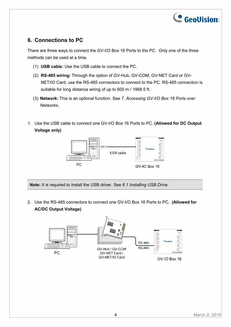
6. Connections to PC
There are three ways to connect the GV-I/O Box 16 Ports to the PC. Only one of the three
methods can be used at a time.
(1) USB cable: Use the USB cable to connect the PC.
(2) RS-485 wiring: Through the option of GV-Hub, GV-COM, GV-NET Card or GV-
NET/IO Card, use the RS-485 connectors to connect to the PC. RS-485 connection is
suitable for long distance wiring of up to 600 m / 1968.5 ft.
(3) Network: This is an optional function. See 7. Accessing GV-I/O Box 16 Ports over
Networks.
1. Use the USB cable to connect one GV-I/O Box 16 Ports to PC. (Allowed for DC Output
Voltage only)
H
Output
DC 12V
G
F
E
RS- 485 RX
RX- 485 TXA
com.ADI 1
USB RX
USB TX
GV-IOBOX 16
Input
DI 2DI 3
DI 4
B
com.BDI 8
DI 7
DI 6
DI 5
C
com.CDI 12
DI 11
DI 10
DI 9
D
com.DDI 16
DI 15
DI 14
DI 13
DO 4
DO 3
DO 2
DO 1
DO 8
DO 7DO 6
DO 5
DO 12
DO 11
DO 10
DO 9
DO 16
DO 15
DO 14
DO 13
com.H
com.G
com.F
com.E
Note: It is required to install the USB driver. See 6.1 Installing USB Drive.
2. Use the RS-485 connectors to connect one GV-I/O Box 16 Ports to PC. (Allowed for
AC/DC Output Voltage)
H
Output
DC 12V
G
F
E
RS- 485 RX
RX- 485 TXA
com.ADI 1
USB RX
USB TX
GV-IOBOX 16
Input
DI 2DI 3
DI 4
B
com.BDI 8
DI 7
DI 6
DI 5
C
com.CDI 12
DI 11
DI 10
DI 9
D
com.DDI 16
DI 15
DI 14
DI 13
DO 4
DO 3
DO 2
DO 1
DO 8
DO 7DO 6
DO 5
DO 12
DO 11
DO 10
DO 9
DO 16
DO 15
DO 14
DO 13
com.H
com.G
com.F
com.E
March 2, 2018 4

March 2, 2018 5
6.1 Installing USB Driver
To use the USB function, it is required to install the driver on the PC. Follow these steps to
install the driver:
1. Download and install the USB Driver from the website.
2. Click Install to install the drivers. When the installation is complete, this message will
appear: Install Successfully.
3. Click Exit to close the dialog box and restart the PC.
To verify the drivers are installed correctly, go to Windows Device Manager after restarting
the PC. Expanding the Ports field, you should see XR21B1411 USB UART. The COM
number in the parenthesis indicates the COM port currently in use.
Note: If you unplug the GV-I/O Box 16 Ports from the PC and connect another GV-I/O Box to the same USB port, the COM port may still be changed. Access the Windows Device Manager again to look up the new COM port number.

6.2 Assigning Addresses to GV-I/O Box
You can connect any GV-IO Box of 4, 8 and 16 ports together through RS-485 wiring. Up to
9 pieces of GV-I/O Box can be chained together to expand the I/O capacity. Use the ID
switch (1~9) to assign addresses 1~9 to each GV-I/O Box.
RS-485 +/-
GV-IO Box (1) GV-IO Box (2) GV-IO Box (9)
RS-485 +/- RS-485 +/-
~
PC
H
Output
DC 12V
G
F
E
RS- 485 RX
RX- 485 TXA
com.ADI 1
USB RX
USB TX
GV-IOBOX 16
Input
DI 2
DI 3
DI 4
B
com.BDI 8
DI 7
DI 6
DI 5
C
com.CDI 12
DI 11
DI 10
DI 9
D
com.DDI 16
DI 15
DI 14
DI 13
DO 4
DO 3
DO 2
DO 1
DO 8
DO 7DO 6
DO 5
DO 12
DO 11
DO 10
DO 9
DO 16
DO 15
DO 14
DO 13
com.H
com.G
com.F
com.E
H
Output
DC 12V
G
F
E
RS- 485 RX
RX- 485 TXA
com.ADI 1
USB RX
USB TX
GV-IOBOX 16
Input
DI 2
DI 3
DI 4
B
com.BDI 8
DI 7
DI 6
DI 5
C
com.CDI 12
DI 11
DI 10
DI 9
D
com.DDI 16
DI 15
DI 14
DI 13
DO 4
DO 3
DO 2
DO 1
DO 8
DO 7DO 6
DO 5
DO 12
DO 11
DO 10
DO 9
DO 16
DO 15
DO 14
DO 13
com.H
com.G
com.F
com.E
H
Output
DC 12V
G
F
E
RS- 485 RX
RX- 485 TXA
com.ADI 1
USB RX
USB TX
GV-IOBOX 16
Input
DI 2
DI 3
DI 4
B
com.BDI 8
DI 7
DI 6
DI 5
C
com.CDI 12
DI 11
DI 10
DI 9
D
com.DDI 16
DI 15
DI 14
DI 13
DO 4
DO 3
DO 2
DO 1
DO 8
DO 7DO 6
DO 5
DO 12
DO 11
DO 10
DO 9
DO 16
DO 15
DO 14
DO 13
com.H
com.G
com.F
com.E
Note: The maximum distance for RS-485 connection is up to 600 m / 1968.5 ft.
ID Switch
B
E
1. Addresses 0 and A to F are NOT functional.
2. Assign the addresses when the power is off.
3. If you want to change the assigned address of the connected GV-I/O
Box, set the switch to the new address and re-plug the power
adaptor.
March 2, 2018 6
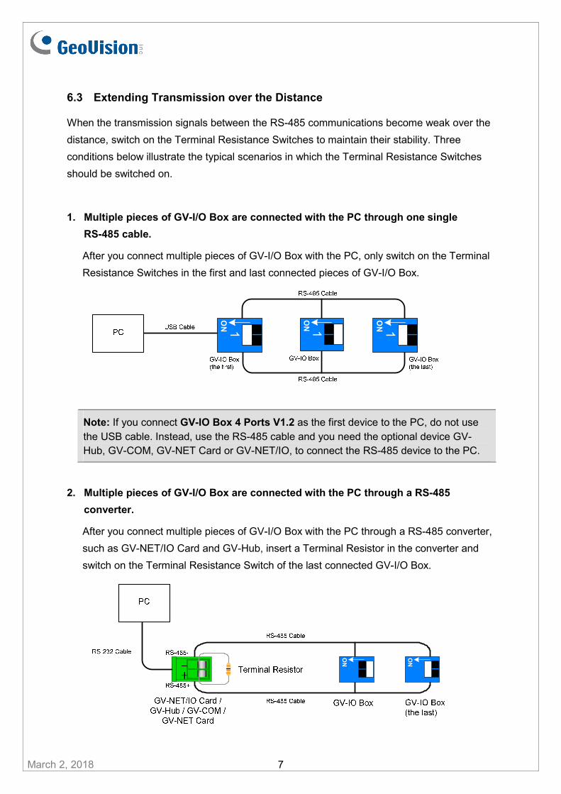
6.3 Extending Transmission over the Distance
When the transmission signals between the RS-485 communications become weak over the
distance, switch on the Terminal Resistance Switches to maintain their stability. Three
conditions below illustrate the typical scenarios in which the Terminal Resistance Switches
should be switched on.
1. Multiple pieces of GV-I/O Box are connected with the PC through one single
RS-485 cable.
After you connect multiple pieces of GV-I/O Box with the PC, only switch on the Terminal
Resistance Switches in the first and last connected pieces of GV-I/O Box.
1O
N1O
N 1O
N
Note: If you connect GV-IO Box 4 Ports V1.2 as the first device to the PC, do not use the USB cable. Instead, use the RS-485 cable and you need the optional device GV-Hub, GV-COM, GV-NET Card or GV-NET/IO, to connect the RS-485 device to the PC.
2. Multiple pieces of GV-I/O Box are connected with the PC through a RS-485
converter.
After you connect multiple pieces of GV-I/O Box with the PC through a RS-485 converter,
such as GV-NET/IO Card and GV-Hub, insert a Terminal Resistor in the converter and
switch on the Terminal Resistance Switch of the last connected GV-I/O Box.
March 2, 2018 7
ON
ON
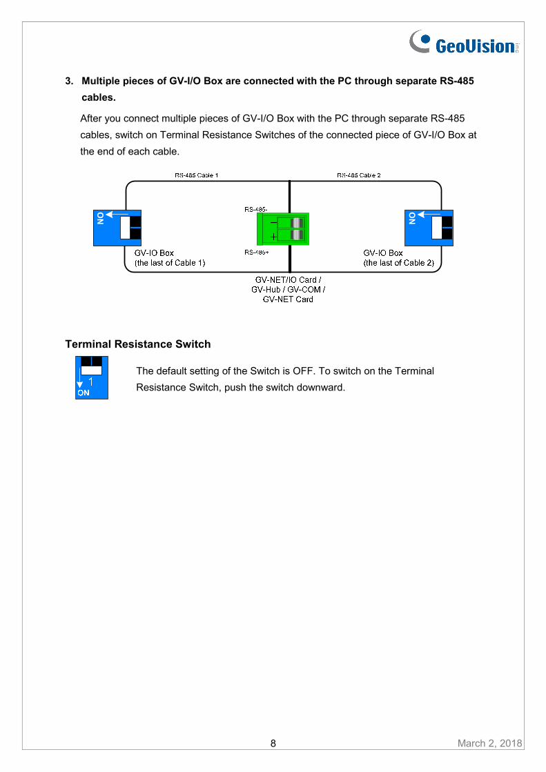
3. Multiple pieces of GV-I/O Box are connected with the PC through separate RS-485
cables.
After you connect multiple pieces of GV-I/O Box with the PC through separate RS-485
cables, switch on Terminal Resistance Switches of the connected piece of GV-I/O Box at
the end of each cable.
ON
ON
Terminal Resistance Switch
The default setting of the Switch is OFF. To switch on the Terminal
Resistance Switch, push the switch downward.
March 2, 2018 8
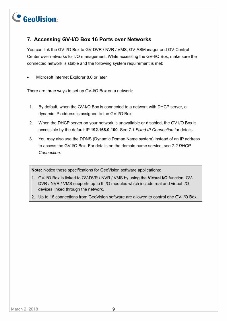
7. Accessing GV-I/O Box 16 Ports over Networks
You can link the GV-I/O Box to GV-DVR / NVR / VMS, GV-ASManager and GV-Control
Center over networks for I/O management. While accessing the GV-I/O Box, make sure the
connected network is stable and the following system requirement is met:
Microsoft Internet Explorer 8.0 or later
There are three ways to set up GV-I/O Box on a network:
1. By default, when the GV-I/O Box is connected to a network with DHCP server, a
dynamic IP address is assigned to the GV-I/O Box.
2. When the DHCP server on your network is unavailable or disabled, the GV-I/O Box is
accessible by the default IP 192.168.0.100. See 7.1 Fixed IP Connection for details.
3. You may also use the DDNS (Dynamic Doman Name system) instead of an IP address
to access the GV-I/O Box. For details on the domain name service, see 7.2 DHCP
Connection.
Note: Notice these specifications for GeoVision software applications:
1. GV-I/O Box is linked to GV-DVR / NVR / VMS by using the Virtual I/O function. GV-DVR / NVR / VMS supports up to 9 I/O modules which include real and virtual I/O devices linked through the network.
2. Up to 16 connections from GeoVision software are allowed to control one GV-I/O Box.
March 2, 2018 9

7.1 Fixed IP Connection
To assign GV-I/O Box to a fixed IP:
1. Open an Internet browser, and type the default IP address https://192.168.0.100. The
login dialog box appears.
2. Type default value admin for both Username and Password, and click OK. This page
appears.
3. In the Machine Name field, edit the name of the connected GV-I/O Box.
4. Click Disable. Type the static IP address information, including IP Address, Subnet
Mask, Default Gateway and Domain Name Server.
5. Click Submit. When the setting is complete, the Status field will indicate Register
Success. Then GV-I/O Box can be accessed through the fixed IP address.
March 2, 2018 10
Note: If want to use the domain name instead of an IP address, you may use the Domain Name Service. For details on domain name service, see 7.2 DHCP Connection.

7.2 DHCP Connection
DDNS (Dynamic Domain Name System) provides another way of accessing GV-I/O Box
when using a dynamic IP from a DHCP server. DDNS assigns a domain name to GV-I/O Box
so that GV servers can always access GV-I/O Box by using the domain name.
To enable the DDNS function, first you should apply for a domain name from the DDNS
service provider’s website. There are 2 providers listed in GV-I/O Box: GeoVision DDNS
Server and DynDNS.org. To register at GeoVision DDNS Server, see the following
instructions. For details on DynDNS, please consult them at www.dyndns.org.
GV-IOBOX 8
Output Input
DC 12V
D
com.D
DO 8
DO 7DO 6
DO 5
C
com.C
DO 4
DO 3DO 2
DO 1
RS- 485 RX
RX- 485 TX
B
com.B
DI 8
DI 7
DI 6
DI 5
A
com.A
DI 4
DI 3
DI 2
DI 1
USB RX
USB TX
Registering a DDNS Domain Name
To obtain a domain name from the GeoVision DDNS Server:
1. Click the GeoVision DDNS button on the Network Configuration page. Or open an
Internet browser and type the Web address http://ns.dipmap.com/register.aspx.
This page appears.
March 2, 2018 11
2. In the Username field, type a name. Username can be up to 16 characters with the
choices of “a ~ z”, “0 ~9”, and “-”. Note that space or “-” cannot be used as the first
character.
3. In the Password filed, type a password. Passwords are case-sensitive and must be at
least 6 characters. Type the password again in the Re-type Password field for
confirmation.
4. In the Word Verification section, type the characters or numbers shown in the box. For
example, type i8UCY in the required field. Word Verification is not case-sensitive.
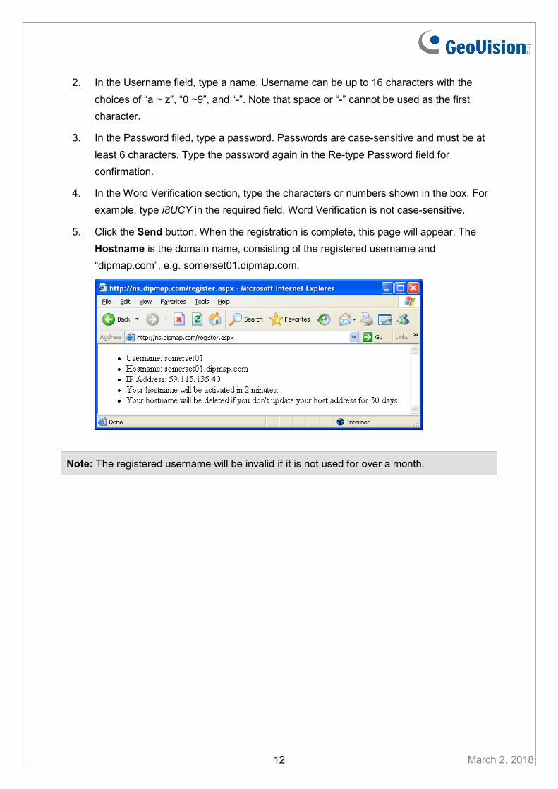
5. Click the Send button. When the registration is complete, this page will appear. The
Hostname is the domain name, consisting of the registered username and
“dipmap.com”, e.g. somerset01.dipmap.com.
Note: The registered username will be invalid if it is not used for over a month.
March 2, 2018 12
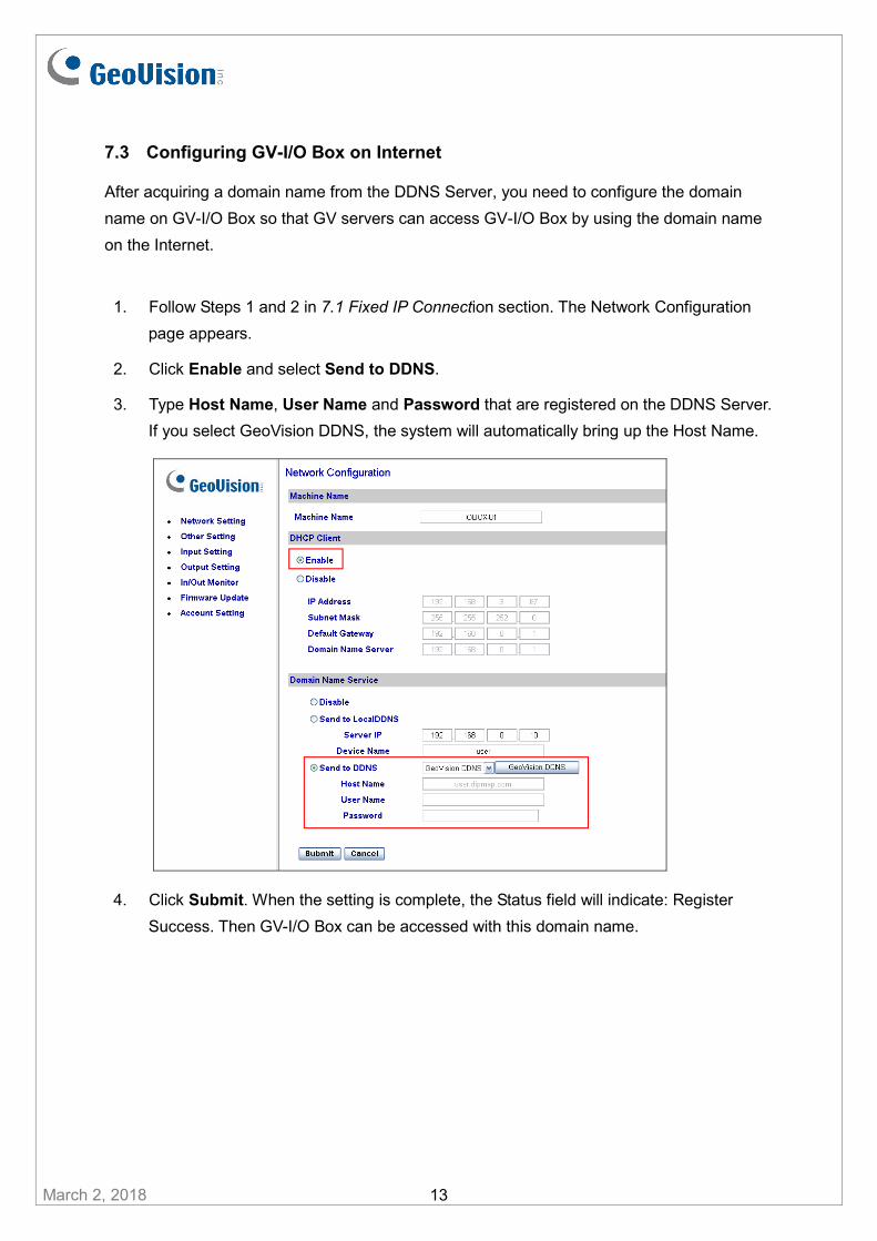
7.3 Configuring GV-I/O Box on Internet
After acquiring a domain name from the DDNS Server, you need to configure the domain
name on GV-I/O Box so that GV servers can access GV-I/O Box by using the domain name
on the Internet.
1. Follow Steps 1 and 2 in 7.1 Fixed IP Connection section. The Network Configuration
page appears.
2. Click Enable and select Send to DDNS.
3. Type Host Name, User Name and Password that are registered on the DDNS Server.
If you select GeoVision DDNS, the system will automatically bring up the Host Name.
March 2, 2018 13
4. Click Submit. When the setting is complete, the Status field will indicate: Register
Success. Then GV-I/O Box can be accessed with this domain name.
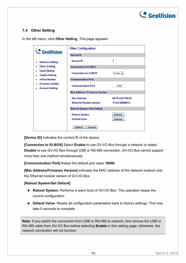
7.4 Other Setting
In the left menu, click Other Setting. This page appears.
[Device ID] Indicates the current ID of the device.
[Connection to IO-BOX] Select Enable to use GV-I/O Box through a network or select
Disable to use GV-I/O Box through USB or RS-485 connection. GV-I/O Box cannot support
more than one method simultaneously.
[Communication Port] Keeps the default port value 10000.
[Mac Address/Firmware Version] Indicates the MAC address of the network medium and
the Ethernet module version of GV-I/O Box.
[Reboot System/Set Default]
Reboot System: Performs a warm boot of GV-I/O Box. This operation keeps the
current configuration.
Default Value: Resets all configuration parameters back to factory settings. This may
take 5 seconds to complete.
March 2, 2018 14
Note: If you switch the connection from USB or RS-485 to network, first remove the USB or RS-485 cable from GV-I/O Box before selecting Enable in this setting page; otherwise, the network connection will not function.
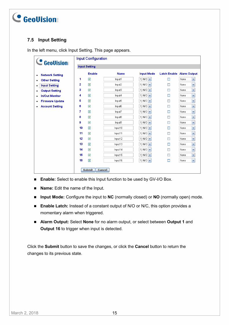
7.5 Input Setting
In the left menu, click Input Setting. This page appears.
Enable: Select to enable this Input function to be used by GV-I/O Box.
Name: Edit the name of the Input.
Input Mode: Configure the input to NC (normally closed) or NO (normally open) mode.
Enable Latch: Instead of a constant output of N/O or N/C, this option provides a
momentary alarm when triggered.
Alarm Output: Select None for no alarm output, or select between Output 1 and
Output 16 to trigger when input is detected.
Click the Submit button to save the changes, or click the Cancel button to return the
changes to its previous state.
March 2, 2018 15
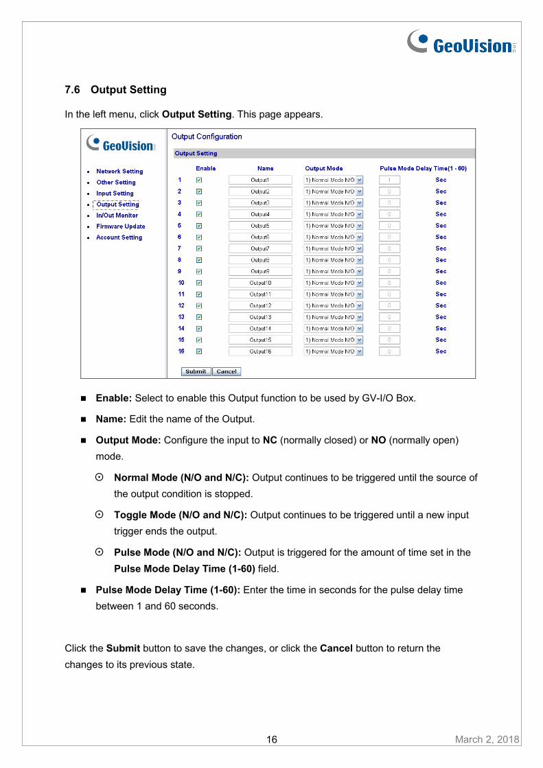
7.6 Output Setting
In the left menu, click Output Setting. This page appears.
Enable: Select to enable this Output function to be used by GV-I/O Box.
Name: Edit the name of the Output.
Output Mode: Configure the input to NC (normally closed) or NO (normally open)
mode.
Normal Mode (N/O and N/C): Output continues to be triggered until the source of
the output condition is stopped.
Toggle Mode (N/O and N/C): Output continues to be triggered until a new input
trigger ends the output.
Pulse Mode (N/O and N/C): Output is triggered for the amount of time set in the
Pulse Mode Delay Time (1-60) field.
Pulse Mode Delay Time (1-60): Enter the time in seconds for the pulse delay time
between 1 and 60 seconds.
Click the Submit button to save the changes, or click the Cancel button to return the
changes to its previous state.
March 2, 2018 16
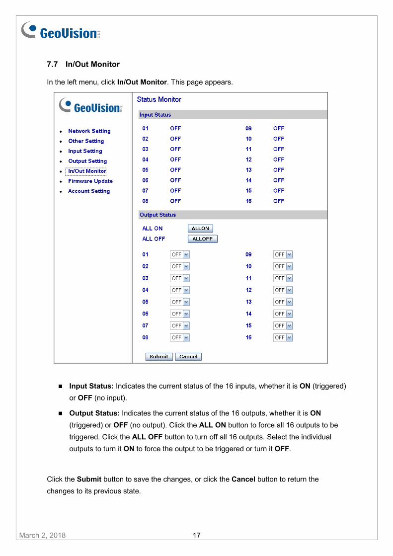
7.7 In/Out Monitor
In the left menu, click In/Out Monitor. This page appears.
Input Status: Indicates the current status of the 16 inputs, whether it is ON (triggered)
or OFF (no input).
Output Status: Indicates the current status of the 16 outputs, whether it is ON
(triggered) or OFF (no output). Click the ALL ON button to force all 16 outputs to be
triggered. Click the ALL OFF button to turn off all 16 outputs. Select the individual
outputs to turn it ON to force the output to be triggered or turn it OFF.
March 2, 2018 17
Click the Submit button to save the changes, or click the Cancel button to return the
changes to its previous state.

8. Updating Firmware
IMPORTANT: For firmware update from Version 1.10 or earlier to the latest version, it is required to access the GV-I/O Box over the network on Windows XP or Windows 7.
To update the firmware of GV-I/O Box, follow the steps below:
1. In the left menu, click Firmware Update. This page appears.
2. Click the Browse… button to open the firmware file (*.bin)
3. Click the Upload button. This update procedure may take 60 seconds to complete.
4. When Update is complete, a dialog box appears and asks you to reboot the system.
5. Click OK. GV-I/O Box starts the Reboot operation.
Note:
1. It is required to reboot GV-I/O Box after updating the firmware. Without rebooting, the firmware update is not complete.
2. The firmware can also be updated through GV-Net Module Utility, which supports simultaneous update of multiple GV-I/O Box and can be downloaded from the website.
3. Updating of firmware through GV-IP Device Utility is only supported when updating from firmware V1.21 or later.
March 2, 2018 18

9. Changing Login ID and Password
In the left menu, click Account Setting. This page appears. You can modify the login name
and password. The password is case sensitive and is limited to 4 characters with the choices
of “a ~ z” and “0 ~ 9”.
10. Specifications
March 2, 2018 19
32-bit Windows 7 / 8 / 8.1 / 10 / Server 2008
OS 64-bit
Windows 7 / 8 / 8.1 / 10 / Server 2008 R2 / Server 2012 R2
Input 16
Dry Contact Input Input Signal
Wet Contact, 9-30V AC/DC
Relay Output 16
Relay Status Normal Open
USB Connection 30V DC, 3A Output Relay Capacitance RS-485 Connection
125 / 250V AC, 3A
30V DC, 3A
Ethernet RJ-45, 10/100 Mbps (Optional)
DC IN DC 12V, 1A
Address 0-9, A-F
Terminal Resistance 120
Operating Temperature 0° C ~50° C / 32°F ~122 °F
Humidity 5% ~ 95% (Non-Condensing)
Dimensions (W x H x D) 180 x 27 x 183 mm / 7.09 x 1.06 x 7.2 in