
The Greatest Challenges in TBM Tunneling: Experiences · PDF fileThe Greatest Challenges in...
8
101 The Greatest Challenges in TBM Tunneling: Experiences from the Field Jim Clark and Steve Chorley The Robbins Company ABSTRACT: TBM tunneling is an ever-increasing prospect for underground construction, and with each new tunnel bored there are unknown elements. When boring through the earth, even extensive Geotechnical Baseline Reports can miss fault lines, water inflows, squeezing ground, rock bursting, and other types of extreme conditions. This paper will draw on the considerable field service experience within Robbins to analyze successful methods of dealing with the most challenging conditions encountered. INTRODUCTION Many tunnel projects are located in areas with rela- tively poor access along the tunnel alignment and bored under extremely high overburden. These two factors often result in limited geological information. It would be reasonable to state that the deeper the tunnel, the greater the level of uncertainties. When faced with these uncertainties everyone involved with project including the owner, the contractor, and the machine supplier must be prepared to tackle geo- logical surprises. This paper describes the problem- atic geological conditions and associated difficulties faced on three separate projects and the measures that were taken to overcome these difficulties. KARGI KIZILIRMAK HYDROELECTRIC PROJECT Background The Kargi Kizilirmak Hydroelectric Project is located on the Sakarya River, near the Beypazarı district of Ankara province in Turkey. The Robbins Company supplied a 9.84 meter diameter Double Shield TBM and continuous conveyor system to Gülermak for excavation of the 11.8 kilometer head race tunnel (see Figure 1). The tunnel is being driven through a mountainside with up to 600 m of over- burden. The geology consists of volcanic rock and softer limestone for the first 3.0 kilometers, followed by harder rock including marble and basalt for the remainder of the tunnel alignment. Due to the varia- tion in geology the ground support regimes range from pre-cast segmental lining for the first 3.0 kilo- meters transitioning into ring beams, rock bolts and shotcrete as the tunnel moves into more competent geology. Several unique features were incorporated into the TBM design to facilitate installation of the various ground support regimes. Issues Encountered (Trapped Cutterhead) The machine was launched in the spring of 2012 and almost immediately encountered geology that was substantially more problematic than was described in the geological reports. The geology consisted of blocky rock, sand and clays. As a countermea- sure that was immediately put into place to avoid the cutterhead becoming stuck in the blocky mate- rial, crews began boring half strokes and half resets. This ensured that there was always the option of rapidly retracting the cutterhead in the event that torque reached critical levels. After boring through 80 meters of these difficult ground conditions, the machine encountered a section of extremely loose running ground with high clay content. A collapse occurred in front of the cutterhead and the cathedral effect resulted in a cavity forming that extended more than 10 m above the crown of the tunnel. The weight of the collapsed material trapped the cutter- head. After several unsuccessful attempts to clean out and restart the cutterhead, consolidation of the ground above and in front of the machine was car- ried out. Injection of polyurethane resins via lances inserted through the cutter housings and muck buck- ets was the method utilized for consolidation opera- tions; however, injection locations were restricted to the available openings and subsequent attempts to restart the cutterhead proved to be unsuccessful. Bypass Tunnel After assessing all the available options it was decided that a bypass tunnel would be required. Robbins Field Service assisted Gülermak with bypass tunnel design and work procedures to free the cutterhead and stabilize the disturbed ground. Blasting techniques were ruled out due to concern over further collapses caused by blast induced
Transcript of The Greatest Challenges in TBM Tunneling: Experiences · PDF fileThe Greatest Challenges in...
101
The Greatest Challenges in TBM Tunneling: Experiences from the Field
Jim Clark and Steve ChorleyThe Robbins Company
ABSTRACT: TBM tunneling is an ever-increasing prospect for underground construction, and with each new tunnel bored there are unknown elements. When boring through the earth, even extensive Geotechnical Baseline Reports can miss fault lines, water inflows, squeezing ground, rock bursting, and other types of extreme conditions. This paper will draw on the considerable field service experience within Robbins to analyze successful methods of dealing with the most challenging conditions encountered.
INTRODUCTION
Many tunnel projects are located in areas with rela-tively poor access along the tunnel alignment and bored under extremely high overburden. These two factors often result in limited geological information. It would be reasonable to state that the deeper the tunnel, the greater the level of uncertainties. When faced with these uncertainties everyone involved with project including the owner, the contractor, and the machine supplier must be prepared to tackle geo-logical surprises. This paper describes the problem-atic geological conditions and associated difficulties faced on three separate projects and the measures that were taken to overcome these difficulties.
KARGI KIZILIRMAK HYDROELECTRIC PROJECT
Background
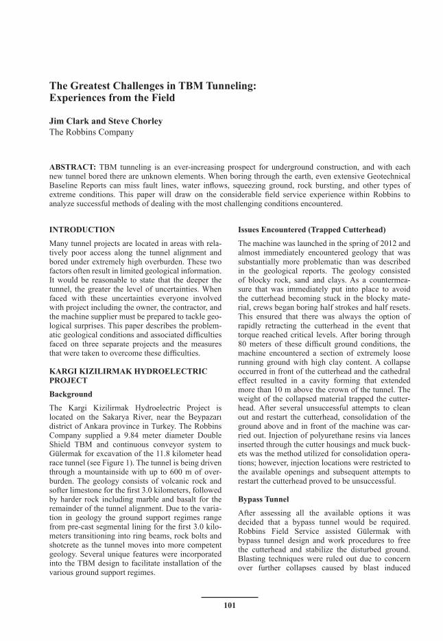
The Kargi Kizilirmak Hydroelectric Project is located on the Sakarya River, near the Beypazarı district of Ankara province in Turkey. The Robbins Company supplied a 9.84 meter diameter Double Shield TBM and continuous conveyor system to Gülermak for excavation of the 11.8 kilometer head race tunnel (see Figure 1). The tunnel is being driven through a mountainside with up to 600 m of over-burden. The geology consists of volcanic rock and softer limestone for the first 3.0 kilometers, followed by harder rock including marble and basalt for the remainder of the tunnel alignment. Due to the varia-tion in geology the ground support regimes range from pre-cast segmental lining for the first 3.0 kilo-meters transitioning into ring beams, rock bolts and shotcrete as the tunnel moves into more competent geology. Several unique features were incorporated into the TBM design to facilitate installation of the various ground support regimes.
Issues Encountered (Trapped Cutterhead)
The machine was launched in the spring of 2012 and almost immediately encountered geology that was substantially more problematic than was described in the geological reports. The geology consisted of blocky rock, sand and clays. As a countermea-sure that was immediately put into place to avoid the cutterhead becoming stuck in the blocky mate-rial, crews began boring half strokes and half resets. This ensured that there was always the option of rapidly retracting the cutterhead in the event that torque reached critical levels. After boring through 80 meters of these difficult ground conditions, the machine encountered a section of extremely loose running ground with high clay content. A collapse occurred in front of the cutterhead and the cathedral effect resulted in a cavity forming that extended more than 10 m above the crown of the tunnel. The weight of the collapsed material trapped the cutter-head. After several unsuccessful attempts to clean out and restart the cutterhead, consolidation of the ground above and in front of the machine was car-ried out. Injection of polyurethane resins via lances inserted through the cutter housings and muck buck-ets was the method utilized for consolidation opera-tions; however, injection locations were restricted to the available openings and subsequent attempts to restart the cutterhead proved to be unsuccessful.
Bypass Tunnel
After assessing all the available options it was decided that a bypass tunnel would be required. Robbins Field Service assisted Gülermak with bypass tunnel design and work procedures to free the cutterhead and stabilize the disturbed ground. Blasting techniques were ruled out due to concern over further collapses caused by blast induced
102
North American Tunneling Conference
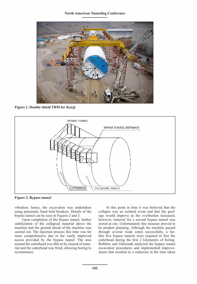
vibration; hence, the excavation was undertaken using pneumatic hand held breakers. Details of the bypass tunnel can be seen in Figures 2 and 3.
Upon completion of the bypass tunnel, further stabilization of the collapsed material above the machine and the ground ahead of the machine was carried out. The injection process this time was far more comprehensive due to the vastly improved access provided by the bypass tunnel. The area around the cutterhead was able to be cleared of mate-rial and the cutterhead was freed, allowing boring to recommence.
At this point in time it was believed that the collapse was an isolated event and that the geol-ogy would improve as the overburden increased; however, material for a second bypass tunnel was stored at site. Unfortunately this measure proved to be prudent planning. Although the machine passed through several weak zones successfully, a fur-ther five bypass tunnels were required to free the cutterhead during the first 2 kilometers of boring. Robbins and Gülermak analyzed the bypass tunnel excavation procedures and implemented improve-ments that resulted in a reduction in the time taken
Figure 1. Double shield TBM for Kargi
Figure 2. Bypass tunnel
103
2014 Proceedings
for bypass operations from 28 days to 14 days. One of the main aspects of the improved procedures was the implementation of breaking out for the bypass tunnel through the telescopic shield area of the TBM rather than the accepted norm of breaking out from the tail shield. This modification resulted in reducing the length of each bypass tunnel by over 4 meters.
Pipe Roof Canopy
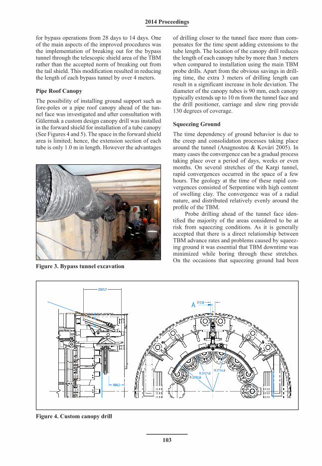
The possibility of installing ground support such as fore-poles or a pipe roof canopy ahead of the tun-nel face was investigated and after consultation with Gülermak a custom design canopy drill was installed in the forward shield for installation of a tube canopy (See Figures 4 and 5). The space in the forward shield area is limited; hence, the extension section of each tube is only 1.0 m in length. However the advantages
of drilling closer to the tunnel face more than com-pensates for the time spent adding extensions to the tube length. The location of the canopy drill reduces the length of each canopy tube by more than 3 meters when compared to installation using the main TBM probe drills. Apart from the obvious savings in drill-ing time, the extra 3 meters of drilling length can result in a significant increase in hole deviation. The diameter of the canopy tubes is 90 mm, each canopy typically extends up to 10 m from the tunnel face and the drill positioner, carriage and slew ring provide 130 degrees of coverage.
Squeezing Ground
The time dependency of ground behavior is due to the creep and consolidation processes taking place around the tunnel (Anagnostou & Kovári 2005). In many cases the convergence can be a gradual process taking place over a period of days, weeks or even months. On several stretches of the Kargi tunnel, rapid convergences occurred in the space of a few hours. The geology at the time of these rapid con-vergences consisted of Serpentine with high content of swelling clay. The convergence was of a radial nature, and distributed relatively evenly around the profile of the TBM.
Probe drilling ahead of the tunnel face iden-tified the majority of the areas considered to be at risk from squeezing conditions. As it is generally accepted that there is a direct relationship between TBM advance rates and problems caused by squeez-ing ground it was essential that TBM downtime was minimized while boring through these stretches. On the occasions that squeezing ground had been
Figure 3. Bypass tunnel excavation
Figure 4. Custom canopy drill
104
North American Tunneling Conference
identified all outstanding maintenance works, repairs and replacement of worn cutters was completed before boring through the zone of concern com-menced. Inevitably, even after taking these precau-tions there were unscheduled stoppages. On many occasions the only successful means of restarting the machine after stoppages in convergence zones was to utilize single shield mode boring. In this mode the TBM gripper shoes are retracted, the main thrust cylinders are closed up and the auxiliary thrust cyl-inders are utilized to propel the machine forward by thrusting off the segmental lining. The typical thrust force for standard boring operations using the main thrust cylinders on the Kargi machine is approxi-mately 21,000 kN. On several occasions thrust force up to 136,000 kN was applied through the auxiliary thrust system before the machine could be freed from squeezing ground. Generally after boring one or two meters in single shield mode the TBM was freed and it was possible to return to double shield mode.
On several stretches of tunnel the rate of conver-gence coupled with the comparative softness of the ground caused the gripper shield to act as a plough and force muck into the telescopic shield area. The buildup of material became so severe that a muck-ing system had to be installed in the telescopic shield area. The system consisted of two electric hoists mounted on a running beam that allowed muck kib-bles to be placed, lifted, and emptied directly onto the TBM conveyor.
Another measure utilized to combat the effects of the squeezing ground was the application of a polymer based biodegradable lubricant to the extra-dos of the TBM shields. Eight injection ports were installed around the perimeter of the forward shield and lubrication was injected when boring through convergence zones. It is difficult to quantify the advantage obtained as there was very little consis-tency in ground conditions and associated thrust pressures; however, it is clear that the application of
lubrication reduced the frictional forces between the shields and converging ground.
Solution (Gear Reduction)
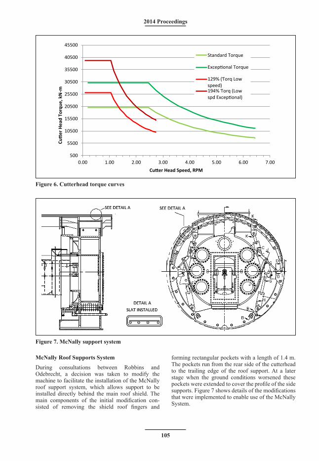
To further mitigate the effects of squeezing ground or collapses, custom-made gear reducers were ordered and retrofitted to the cutterhead motors as a solution. They were installed between the drive motor and the primary two-stage planetary gearboxes. During standard boring operations the gear reducers oper-ate at a ratio of 1:1, offering no additional reduction and allowing the cutterhead to reach design speeds for hard rock boring. When the machine encounters loose or squeezing ground the reducers are engaged, which results in a reduction in cutterhead speed but the available torque is increased. Figure 6 shows the torque curves for both standard and reduced gearing.
Since the installation of the canopy drill and the increase in available cutterhead torque, the TBM has traversed several sections of adverse geology includ-ing stretches of severe convergence without becom-ing trapped. As of November 2013 over 4,250 m of boring has been completed.
LOS OLMOS
The Los Olmos tunnel is a 12.5 km long water transfer tunnel that was bored through the Andes Mountains in Peru. Odebrecht was the main contrac-tor and the tunnel was driven using a 5.3 m diameter Robbins main beam TBM. It is the World’s second deepest civil works tunnel after the Gotthard base tunnel with overburden of up to 2000 meters. The tunnel alignment is through complex geology con-sisting of quartz porphyry, andesite, and tuff with rock strengths ranging from 60 to 225 MPa. The machine crossed over 400 fault lines including two major faults of approximately 50 m wide.
The machine was launched in March 2007 and by February 2008 it had bored over four kilometers. The geology over the first 4,000 m of boring was far more challenging than was anticipated. As the height of the overburden increased, the geological conditions became gradually more severe and long stretches of extremely loose, blocky ground were encountered. The rock stresses caused by the high overburden also resulted in over 16,000 recorded rock bursting events. TBM utilization was as low as 18.7% of working time because rock support installation was requiring a very high 43.5% of the working time (Roby & Willis 2008). One of the main problems faced was ground deterioration and the resulting falls of blocky ground. The majority of these events occurred during the time taken for the newly excavated bore to pass behind the rear fingers of the roof shield, where ring beams and mesh are installed.
Figure 5. Canopy tube drilling
105
2014 Proceedings
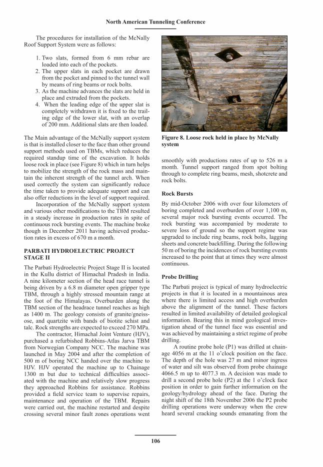
McNally Roof Supports System
During consultations between Robbins and Odebrecht, a decision was taken to modify the machine to facilitate the installation of the McNally roof support system, which allows support to be installed directly behind the main roof shield. The main components of the initial modification con-sisted of removing the shield roof fingers and
forming rectangular pockets with a length of 1.4 m. The pockets run from the rear side of the cutterhead to the trailing edge of the roof support. At a later stage when the ground conditions worsened these pockets were extended to cover the profile of the side supports. Figure 7 shows details of the modifications that were implemented to enable use of the McNally System.
500
5500
10500
15500
20500
25500
30500
35500
40500
45500
0.00 1.00 2.00 3.00 4.00 5.00 6.00 7.00
Cutt
er H
ead
Torq
ue, k
N-m
Cutter Head Speed, RPM
Standard Torque
Exceptional Torque
129% (Ƭorq Low speed)194% Ƭorq (Low spd Exceptional)
Figure 6. Cutterhead torque curves
Figure 7. McNally support system
106
North American Tunneling Conference
The procedures for installation of the McNally Roof Support System were as follows:
1. Two slats, formed from 6 mm rebar are loaded into each of the pockets.
2. The upper slats in each pocket are drawn from the pocket and pinned to the tunnel wall by means of ring beams or rock bolts.
3. As the machine advances the slats are held in place and extruded from the pockets.
4. When the leading edge of the upper slat is completely withdrawn it is fixed to the trail-ing edge of the lower slat, with an overlap of 200 mm. Additional slats are then loaded.
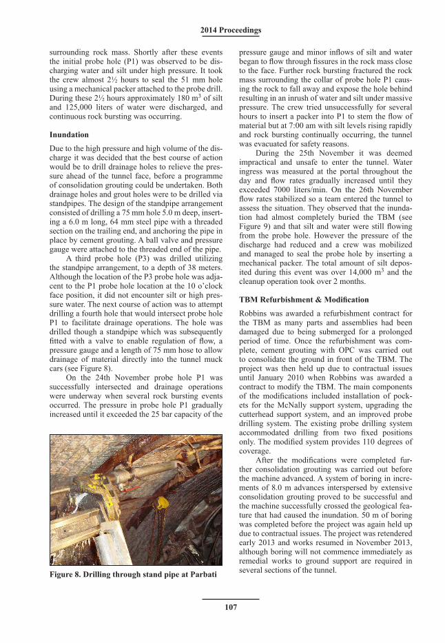
The Main advantage of the McNally support system is that is installed closer to the face than other ground support methods used on TBMs, which reduces the required standup time of the excavation. It holds loose rock in place (see Figure 8) which in turn helps to mobilize the strength of the rock mass and main-tain the inherent strength of the tunnel arch. When used correctly the system can significantly reduce the time taken to provide adequate support and can also offer reductions in the level of support required.
Incorporation of the McNally support system and various other modifications to the TBM resulted in a steady increase in production rates in spite of continuous rock bursting events. The machine broke though in December 2011 having achieved produc-tion rates in excess of 670 m a month.
PARBATI HYDROELECTRIC PROJECT STAGE II
The Parbati Hydroelectric Project Stage II is located in the Kullu district of Himachal Pradesh in India. A nine kilometer section of the head race tunnel is being driven by a 6.8 m diameter open gripper type TBM, through a highly stressed mountain range at the foot of the Himalayas. Overburden along the TBM section of the headrace tunnel reaches as high as 1400 m. The geology consists of granite/gneiss-ose, and quartzite with bands of biotite schist and talc. Rock strengths are expected to exceed 270 MPa.
The contractor, Himachal Joint Venture (HJV), purchased a refurbished Robbins-Atlas Jarva TBM from Norwegian Company NCC. The machine was launched in May 2004 and after the completion of 500 m of boring NCC handed over the machine to HJV. HJV operated the machine up to Chainage 1300 m but due to technical difficulties associ-ated with the machine and relatively slow progress they approached Robbins for assistance. Robbins provided a field service team to supervise repairs, maintenance and operation of the TBM. Repairs were carried out, the machine restarted and despite crossing several minor fault zones operations went
smoothly with productions rates of up to 526 m a month. Tunnel support ranged from spot bolting through to complete ring beams, mesh, shotcrete and rock bolts.
Rock Bursts
By mid-October 2006 with over four kilometers of boring completed and overburden of over 1,100 m, several major rock bursting events occurred. The rock bursting was accompanied by moderate to severe loss of ground so the support regime was upgraded to include ring beams, rock bolts, lagging sheets and concrete backfilling. During the following 50 m of boring the incidences of rock bursting events increased to the point that at times they were almost continuous.
Probe Drilling
The Parbati project is typical of many hydroelectric projects in that it is located in a mountainous area where there is limited access and high overburden above the alignment of the tunnel. These factors resulted in limited availability of detailed geological information. Bearing this in mind geological inves-tigation ahead of the tunnel face was essential and was achieved by maintaining a strict regime of probe drilling.
A routine probe hole (P1) was drilled at chain-age 4056 m at the 11 o’clock position on the face. The depth of the hole was 27 m and minor ingress of water and silt was observed from probe chainage 4066.5 m up to 4077.3 m. A decision was made to drill a second probe hole (P2) at the 1 o’clock face position in order to gain further information on the geology/hydrology ahead of the face. During the night shift of the 18th November 2006 the P2 probe drilling operations were underway when the crew heard several cracking sounds emanating from the
Figure 8. Loose rock held in place by McNally system
107
2014 Proceedings
surrounding rock mass. Shortly after these events the initial probe hole (P1) was observed to be dis-charging water and silt under high pressure. It took the crew almost 2½ hours to seal the 51 mm hole using a mechanical packer attached to the probe drill. During these 2½ hours approximately 180 m3 of silt and 125,000 liters of water were discharged, and continuous rock bursting was occurring.
Inundation
Due to the high pressure and high volume of the dis-charge it was decided that the best course of action would be to drill drainage holes to relieve the pres-sure ahead of the tunnel face, before a programme of consolidation grouting could be undertaken. Both drainage holes and grout holes were to be drilled via standpipes. The design of the standpipe arrangement consisted of drilling a 75 mm hole 5.0 m deep, insert-ing a 6.0 m long, 64 mm steel pipe with a threaded section on the trailing end, and anchoring the pipe in place by cement grouting. A ball valve and pressure gauge were attached to the threaded end of the pipe.
A third probe hole (P3) was drilled utilizing the standpipe arrangement, to a depth of 38 meters. Although the location of the P3 probe hole was adja-cent to the P1 probe hole location at the 10 o’clock face position, it did not encounter silt or high pres-sure water. The next course of action was to attempt drilling a fourth hole that would intersect probe hole P1 to facilitate drainage operations. The hole was drilled though a standpipe which was subsequently fitted with a valve to enable regulation of flow, a pressure gauge and a length of 75 mm hose to allow drainage of material directly into the tunnel muck cars (see Figure 8).
On the 24th November probe hole P1 was successfully intersected and drainage operations were underway when several rock bursting events occurred. The pressure in probe hole P1 gradually increased until it exceeded the 25 bar capacity of the
pressure gauge and minor inflows of silt and water began to flow through fissures in the rock mass close to the face. Further rock bursting fractured the rock mass surrounding the collar of probe hole P1 caus-ing the rock to fall away and expose the hole behind resulting in an inrush of water and silt under massive pressure. The crew tried unsuccessfully for several hours to insert a packer into P1 to stem the flow of material but at 7:00 am with silt levels rising rapidly and rock bursting continually occurring, the tunnel was evacuated for safety reasons.
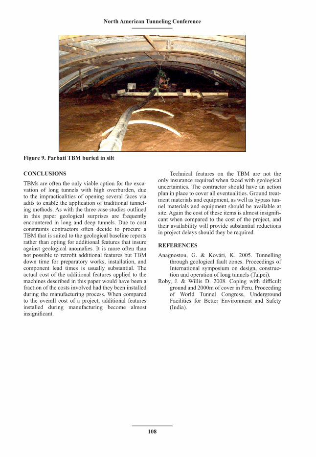
During the 25th November it was deemed impractical and unsafe to enter the tunnel. Water ingress was measured at the portal throughout the day and flow rates gradually increased until they exceeded 7000 liters/min. On the 26th November flow rates stabilized so a team entered the tunnel to assess the situation. They observed that the inunda-tion had almost completely buried the TBM (see Figure 9) and that silt and water were still flowing from the probe hole. However the pressure of the discharge had reduced and a crew was mobilized and managed to seal the probe hole by inserting a mechanical packer. The total amount of silt depos-ited during this event was over 14,000 m3 and the cleanup operation took over 2 months.
TBM Refurbishment & Modification
Robbins was awarded a refurbishment contract for the TBM as many parts and assemblies had been damaged due to being submerged for a prolonged period of time. Once the refurbishment was com-plete, cement grouting with OPC was carried out to consolidate the ground in front of the TBM. The project was then held up due to contractual issues until January 2010 when Robbins was awarded a contract to modify the TBM. The main components of the modifications included installation of pock-ets for the McNally support system, upgrading the cutterhead support system, and an improved probe drilling system. The existing probe drilling system accommodated drilling from two fixed positions only. The modified system provides 110 degrees of coverage.
After the modifications were completed fur-ther consolidation grouting was carried out before the machine advanced. A system of boring in incre-ments of 8.0 m advances interspersed by extensive consolidation grouting proved to be successful and the machine successfully crossed the geological fea-ture that had caused the inundation. 50 m of boring was completed before the project was again held up due to contractual issues. The project was retendered early 2013 and works resumed in November 2013, although boring will not commence immediately as remedial works to ground support are required in several sections of the tunnel.Figure 8. Drilling through stand pipe at Parbati
108
North American Tunneling Conference
CONCLUSIONS
TBMs are often the only viable option for the exca-vation of long tunnels with high overburden, due to the impracticalities of opening several faces via adits to enable the application of traditional tunnel-ing methods. As with the three case studies outlined in this paper geological surprises are frequently encountered in long and deep tunnels. Due to cost constraints contractors often decide to procure a TBM that is suited to the geological baseline reports rather than opting for additional features that insure against geological anomalies. It is more often than not possible to retrofit additional features but TBM down time for preparatory works, installation, and component lead times is usually substantial. The actual cost of the additional features applied to the machines described in this paper would have been a fraction of the costs involved had they been installed during the manufacturing process. When compared to the overall cost of a project, additional features installed during manufacturing become almost insignificant.
Technical features on the TBM are not the only insurance required when faced with geological uncertainties. The contractor should have an action plan in place to cover all eventualities. Ground treat-ment materials and equipment, as well as bypass tun-nel materials and equipment should be available at site. Again the cost of these items is almost insignifi-cant when compared to the cost of the project, and their availability will provide substantial reductions in project delays should they be required.
REFERENCES
Anagnostou, G. & Kovári, K. 2005. Tunnelling through geological fault zones. Proceedings of International symposium on design, construc-tion and operation of long tunnels (Taipei).
Roby, J. & Willis D. 2008. Coping with difficult ground and 2000m of cover in Peru. Proceeding of World Tunnel Congress, Underground Facilities for Better Environment and Safety (India).
Figure 9. Parbati TBM buried in silt


![TBM 렌탈솔루션 - cafe24mrrental.cafe24.com/tbm/tbmrs_service_introduction.pdf · 01. TBM 렌탈솔루션소개 [이미지출처: 효성에프엠에스뉴스레터(2019.01.28)]](https://static.fdocuments.net/doc/165x107/5ece13d36c14a753b559968e/tbm-eoefe-01-tbm-eoefeoeeoe-eoe-ee20190128.jpg)


