
The Gotfried PC.C - Surgico · 2017-04-09 · following incremental drilling from 7 to 9.3 mm, ......
28
OPERATIVE TECHNIQUE ALWAYS INNOVATING The Gotfried PC.C.P for Percutaneous Compression Plating of Pertrochanteric Hip Fractures By Dr. Y. Gotfried MD.M.S.
Transcript of The Gotfried PC.C - Surgico · 2017-04-09 · following incremental drilling from 7 to 9.3 mm, ......

O P E R A T I V E T E C H N I Q U E
ALWAYS INNOVATING
The Gotfried PC.C.Pfor Percutaneous Compression Plating
of Pertrochanteric Hip Fractures
By Dr. Y. Gotfried MD.M.S.

Page N°
INTRODUCTION . . . . . . . . . . . . . . . . . . . . . . . . . . . . . . . . . . . . . . . . . . . . . . . . . . . . . . . . . . . . . . . . . . . . . . . . . . . . . . . . . . . . . . . . . . . . . . . . . . . . . . . . . . . . . . . . . . . . . . . . . . . . . . 1
REFERENCES . . . . . . . . . . . . . . . . . . . . . . . . . . . . . . . . . . . . . . . . . . . . . . . . . . . . . . . . . . . . . . . . . . . . . . . . . . . . . . . . . . . . . . . . . . . . . . . . . . . . . . . . . . . . . . . . . . . . . . . . . . . . . . . . . . . 2
EQUIPMENT REQUIRED . . . . . . . . . . . . . . . . . . . . . . . . . . . . . . . . . . . . . . . . . . . . . . . . . . . . . . . . . . . . . . . . . . . . . . . . . . . . . . . . . . . . . . . . . . . . . . . . . . . . . . . . . . . . . . . . . . . 3
CLEANING AND STERILIZATION. . . . . . . . . . . . . . . . . . . . . . . . . . . . . . . . . . . . . . . . . . . . . . . . . . . . . . . . . . . . . . . . . . . . . . . . . . . . . . . . . . . . . . . . . . . . . . . . . . . . . . 6
OPERATIVE TECHNIQUE . . . . . . . . . . . . . . . . . . . . . . . . . . . . . . . . . . . . . . . . . . . . . . . . . . . . . . . . . . . . . . . . . . . . . . . . . . . . . . . . . . . . . . . . . . . . . . . . . . . . . . . . . . . . . . . . . . 7
POST-OPERATIVE MANAGEMENT . . . . . . . . . . . . . . . . . . . . . . . . . . . . . . . . . . . . . . . . . . . . . . . . . . . . . . . . . . . . . . . . . . . . . . . . . . . . . . . . . . . . . . . . . . . . . . . . . . . . 24
CONTENTS
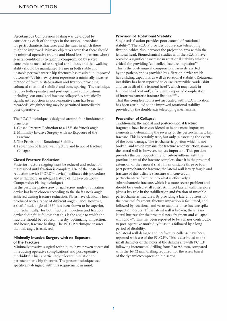
Percutaneous Compression Plating was developed byconsidering each of the stages in the surgical procedurefor pertrochanteric fractures and the ways in which thesemight be improved. Primary objectives were that there shouldbe minimal operative trauma and blood loss in patients whosegeneral condition is frequently compromised by severeconcomitant medical or surgical conditions, and that walkingability should be maintained. Its use in both stable andunstable pertrochanteric hip fractures has resulted in improvedoutcomes1,2,3. This new system represents a minimally invasivemethod of fracture stabilization and fixation, providingenhanced rotational stability4 and bone sparing6. The techniquereduces both operative and post-operative complicationsincluding “cut outs” and fracture collapse1,2. A statisticallysignificant reduction in post-operative pain has beenrecorded3. Weightbearing may be permitted immediately post-operatively.
The PC.C.P technique is designed around four fundamentalprinciples:1. Closed Fracture Reduction to a 135° shaft/neck angle 2. Minimally Invasive Surgery with no Exposure of the
Fracture3. The Provision of Rotational Stability4. Prevention of lateral wall fracture and hence of fracture
Collapse
Closed Fracture Reduction:Posterior fracture sagging must be reduced and reductionmaintained until fixation is complete. Use of the posteriorreduction device (PORD™ device) facilitates this procedureand is therefore an integral feature of the PercutaneousCompression Plating technique1.In the past, the plate-screw or nail-screw angle of a fixationdevice has been chosen according to the shaft / neck angleachieved during fracture reduction. Plates have classically beenproduced with a range of different angles. Since, however,a shaft / neck angle of 135° has been shown to be superior,biomechanically, for both fracture impaction and fixationdevice sliding7,8, it follows that this is the angle to which thefracture should be reduced, thereby optimizing impaction,and hence, fracture healing. The PC.C.P technique ensures that this angle is achieved.
Minimally Invasive Surgery with no Exposureof the Fracture:Minimally invasive surgical techniques have proven successfulin reducing operative complications and post-operativemorbidity9. This is particularly relevant in relation topertrochanteric hip fractures. The present technique wasspecifically designed with this requirement in mind.
Provision of Rotational Stability:Single-axis fixation provides poor control of rotationalstability10. The PC.C.P provides double-axis telescopingfixation, which also increases the projection area within thefemoral head. Biomechanical studies with the PC.C.P haverevealed a significant increase in rotational stability which iscritical for providing “controlled fracture impaction”4.This is the post-surgical compression, passively exerted by the patient, and is provided by a fixation device which has a sliding capability, as well as rotational stability. Rotationalinstability has been reported to cause irreversible caudal shiftand varus tilt of the femoral head11, which may result infemoral head “cut out”, a frequently reported complication of intertrochanteric fracture fixation12,13,14.That this complication is not associated with PC.C.P fixationhas been attributed to the improved rotational stabilityprovided by the double axis telescoping mechanism.
Prevention of Collapse:Traditionally, the medial and postero-medial fracturefragments have been considered to be the most importantelements in determining the severity of the pertrochanteric hipfracture. This is certainly true, but only in assessing the extentof the bony damage. The trochanteric portion which is notbroken, and which remains for fracture reconstruction, namelythe lateral wall is, however, no less important. This portionprovides the best opportunity for osteosynthesis with theproximal part of the fracture complex, since it is the proximalextension of the femoral shaft. In an unstable three or fourpart pertrochanteric fracture, the lateral wall is very fragile andfracture of this delicate structure will convert anpertrochanteric fracture into what is effectively asubtrochanteric fracture, which is a more severe problem andshould be avoided at all costs5. An intact lateral wall, therefore,plays a key role in the stabilization and fixation of unstablepertrochanteric fractures. By providing a lateral buttress forthe proximal fragment, fracture impaction is facilitated, andfollowed by rotational and varus stability once fracture spikeimpaction occurs. If the lateral wall is broken, there is nolateral buttress for the proximal neck fragment and collapsewill follow5,6. This has been reported to be a major contributorto post-operative morbidity15,16 as it is followed by a longperiod of disability.No lateral wall damage and no fracture collapse have beenreported with use of the PC.C.P1,2. This is attributed to thesmall diameter of the holes at the drilling site with PC.C.Pfollowing incremental drilling from 7 to 9.3 mm, comparedwith the 16-32 mm drilling required for the screw barrel of the dynamic/compression hip screw.
1
INTRODUCTION

1. Gotfried Y. Percutaneous compression plating of intertrochanteric hipfractures.J Orthop Trauma 2000; 14: 490-52. Krasheninnikoff M, Gramkow J, Tørholm C. Gotfried PC. CP: a newmethod for osteosynthesis of intertrochanteric fractures of the femur. ActaOrthop Scand 1998; 280 (suppl): 30-13. Janzing HM, Houben BJ, Brandt SE et al. The Gotfried PercutaneousCompression Plate versus the Dynamic Hip Screw in the treatment ofpertrochanteric hip fractures: minimal invasive treatment reduces operativetime and postoperative pain. J Trauma 2002; 52: 293-8 4. Gotfried Y, Cohen B, Rotem A. Biomechanical Evaluation of thePercutaneous Compression Plating System for Hip Fractures. J OrthopTrauma 2002; 16: 644-505. Gotfried Y. Pantrochanteric Hip Fractures: An Entity. J Bone Joint Surg[Br] 2000; 82-B: Suppl III: 2356. Gotfried Y. Percutaneous Compression Plating for Intertrochanteric HipFractures: Treatment Rationale. Orthopaedics 2002; 25: 647-527. Meislin RJ, Zucherman JD, Kummer FJ, Frankel VH. A biomechanicalanalysis of the sliding hip screw: the question of plate angle. J OrthopTrauma 1990; 4: 130-68. Koval KJ, Zucherman JD. Hip fractures II: evaluation and treatment ofintertrochanteric fractures. J Am Acad Orthop Surg 1994; 2: 150-69. Meinero M, Melotti G, Mouret PH. Laparoscopic Surgery. Milan, Italy:Masson; 199410. Swiontkowski MF, Harrington RM, Keller TS, Van Patten PK. Torsionand bending analysis of internal fixation techniques for femoral neckfractures: the role of implant design and bone density. J Orthop Res 1987; 5:433-44 11. Claes L, Becker C, Simancher M, Hoellen I. Improvement in theprimary stability of the dynamic hip screw osteosynthesis in unstable,pertrochanteric fractures of osteoporotic bones by a new glass ionomercement [German] Unfallchirurg 1995;98: 111-2312. Adams CI, Robinson CM, Court-Brown CM, McQueen MM.Prospective randomized controlled trial of an intramedullary nail versusdynamic screw and plate of intertrochanteric fracture of the femur. JOrthop Trauma 2001; 15: 394-40013. Parker MJ. Cutting-out of the dynamic hip screw related to its position.J Bone Joint Surg [Br] 1992; 74B: 62514. Davis TR, Sher JL, Horsman A, Simpson M, Porter BB, Checketts RG.Intertrochanteric femoral fractures. Mechanical failure after internalfixation. J Bone Joint Surg [Br] 1990; 72B: 26-3115. Bendo JA, Weiner LS, Strauss E, Yang E. Collapse of intertrochantericfractures fixed with sliding screws. Orthopaedic Review 1994; 30-716. Stappaerts KH, Deldycke J, Broos PL, Staes FF, Rommens PH, Claes P.Treatment of unstable peritrochanteric fractures in elderly patients with acompression hip screw or with the Vandeputte (VDP) endoprosthesis: aprospective randomized study.J Orthop Trauma 1995; 9: 292-7
2
REFERENCES
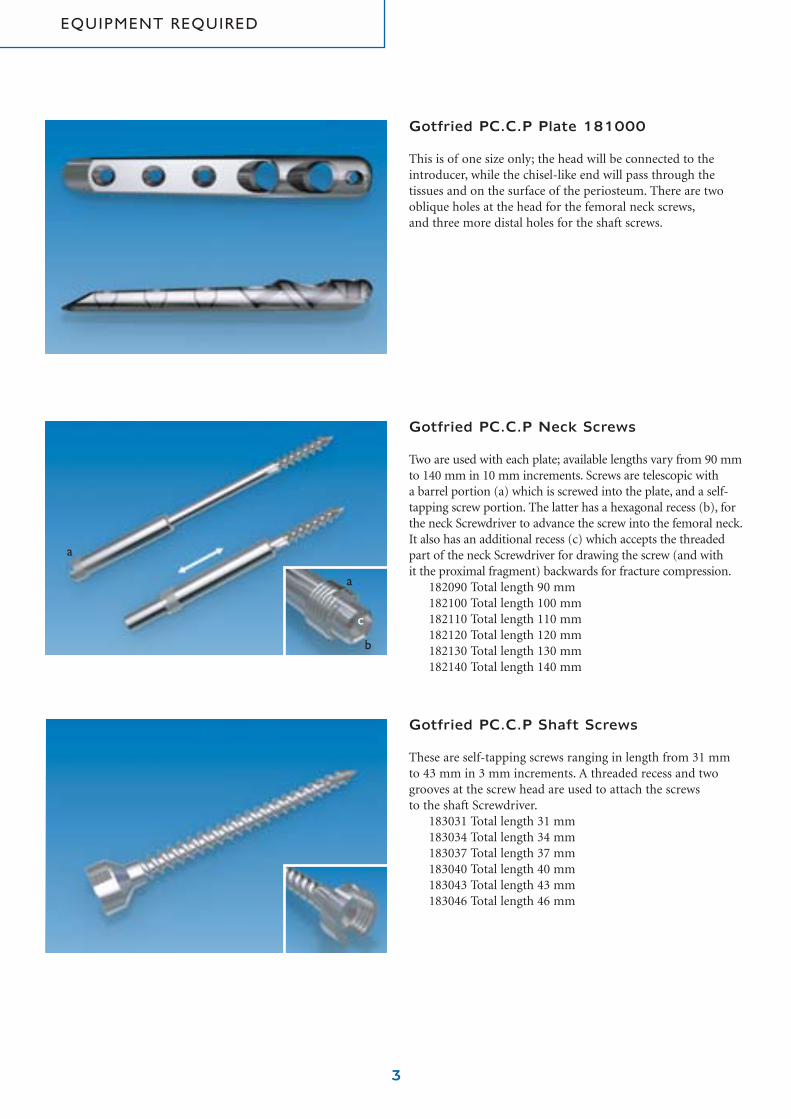
Gotfried PC.C.P Plate 181000
This is of one size only; the head will be connected to theintroducer, while the chisel-like end will pass through thetissues and on the surface of the periosteum. There are twooblique holes at the head for the femoral neck screws,and three more distal holes for the shaft screws.
Gotfried PC.C.P Neck Screws
Two are used with each plate; available lengths vary from 90 mmto 140 mm in 10 mm increments. Screws are telescopic with a barrel portion (a) which is screwed into the plate, and a self-tapping screw portion. The latter has a hexagonal recess (b), forthe neck Screwdriver to advance the screw into the femoral neck.It also has an additional recess (c) which accepts the threadedpart of the neck Screwdriver for drawing the screw (and with it the proximal fragment) backwards for fracture compression.
182090 Total length 90 mm182100 Total length 100 mm182110 Total length 110 mm182120 Total length 120 mm182130 Total length 130 mm182140 Total length 140 mm
Gotfried PC.C.P Shaft Screws
These are self-tapping screws ranging in length from 31 mmto 43 mm in 3 mm increments. A threaded recess and twogrooves at the screw head are used to attach the screws to the shaft Screwdriver.
183031 Total length 31 mm183034 Total length 34 mm183037 Total length 37 mm183040 Total length 40 mm183043 Total length 43 mm183046 Total length 46 mm
3
a
a
b
c
EQUIPMENT REQUIRED

4
Supplementary Equipment
PORD™ Device 110000- No. 10 Scalpel Blade- 18 Gauge Spinal Needle- Metzenbaum scissors- Mallet
Denotes available from Orthofix
210000 PC.C.P Template
190000 Quick Coupler
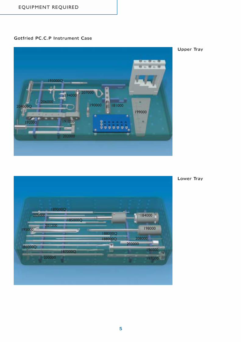
PartNo. Description Quant.180000 Gotfried PC.C.P. instrument set 1
complete, consisting of:184000 Neck Screwdriver 1185000Q Shaft Screwdriver 1186000Q 7.0 mm Drill Bit 1187000Q 9.3 mm Drill Bit 1188000Q Shaft Step Drill 2189000Q Main Guide 1190000 Quick Coupler 1191000 Introducer 1192000 Butterfly Screw 1193000Q Butterfly Pin 1194000 Bolt 2195000 Main Sleeve 1196000 Neck First Sleeve 1197000 Neck Second Sleeve 1198000 Trocar - Neck 1199000 Gauge Aluminium 1200000 Impactor 1201200 Aiming Guide 1202000 Bone Hook Adapter 1203000 Shaft Sleeve 1204000Q Trocar - Shaft 1205000 Depth Gauge 1206000 Skin Retractor 1207000 Bone Hook 1208000 Fixation Wire 1209000 PC.C.P Instrument Case empty 1210000 PC.C.P Template 1
Gotfried PC.C.P Instrument Tray Kit
EQUIPMENT REQUIRED
5
Upper Tray
Lower Tray
191000
202000
206000204000Q
192000
181000190000
207000194000
193000Q
189000Q
199000
201200
205000
200000
198000
184000
197000
203000208000
188000Q188000Q
185000Q
186000Q
195000
187000Q 196000
Gotfried PC.C.P Instrument Case
EQUIPMENT REQUIRED

Cleaning
Cleaning should be performed immediately after eachprocedure, before blood, saline and debris are dry.Rinse with running hot water or immerse and agitate in a milddetergent bath with near neutral pH (7.0 to 8.0) and, wheneverpossible, distilled or demineralized water.Avoid the use of abrasive pads. Ultrasonic cleaning in a hotdetergent bath with the same pH limits will provide the mostefficient cleaning. After cleaning rinse and dry the instrumentsfor storage. The Neck Screwdriver and bone hook MUST betaken apart to insure adequate cleaning of all parts.
Lubrication by dipping in a water - soluble antimicrobiallubricant will help protect instruments against staining and corrosion. Follow lubricant manufacturer’s instructions.These lubricants will not affect the sterilization process.
After cleaning, disinfection may be performed by immersion in a disinfectant solution such as Activated Glutaraldehyde(CIDEX) followed by rinsing and drying.N.B.: As disinfection alone is not adequate, instruments should be sterilized before each procedure.
Sterilization
Prior to surgical use, the Instruments, Plates and Screws shouldbe cleaned as described above and sterilized by a validatedmethod in accordance with the sterilizer manufacturerrecommendations and AAMI and ISO guidelines.
Recommended validated parameters:
Unwrapped “Flash” Gravity-Displacement Steam Sterilization• Sterilizer type: Gravity• Minimum temperature: 132° C• Full cycle time: 20 minutes• Minimum dry time: 0 minutes• Instrument configuration: Unwrapped
Prevacuum Steam Sterilization• Sterilizer type: Prevacuum• Preconditioning pulses: 3• Minimum temperature: 134° C• Full cycle time: 3 minutes• Minimum dry time: 0 minutes• Instrument configuration: Individually wrapped
6
CLEANING AND STERILIZATION

7
Fracture Reduction in the Frontal Plane
The patient is placed on a fracture table, and initial reductionobtained by traction under image intensification.
With the image of the proximal portion of the femur on the screen, the plastic template (210000) with a picture of the device in situ, is placed over it. Traction is then adjusted if necessary, to arrive at a neck-shaft angle of 135 degrees and to ensure that the more distal neck screw will lie 2-3 mmabove the femoral calcar.
The arrow on the template indicates the position at which a spinal needle will shortly be inserted to define the positionof the first skin incision.
Plastic template (overlay) for Image Intensifier
OPERATIVE TECHNIQUE

8
Posterior Reduction of the Fracture
Any posterior sagging at the fracture site should now becorrected and maintained using the dedicated PosteriorReduction (PORD™) Device. This device is easily attached tomost fracture tables.
Position the patient on the fracture table.Slide the Clark Attachment on to the side rail of the fracturetable. Insert the vertical post of the Box Bracket into the ClarkAttachment from beneath and tighten the clamp on the postso that the bracket is held securely.
Assemble the PORD™ device in the following way: Slide the Horizontal Bar through the Box Bracket with its curvedportion facing the fracture table.This curved section is designed to accept the C-arm of the
Image Intensifier.
The Screw Jack of the Limb Support should be seatedcompletely within the Housing of the Horizontal bar with theNut turned so that it lies just beneath the Radiolucent Ledge.
OPERATIVE TECHNIQUE

9
Operative Procedure
The patient is prepped and draped in the normal manner.The Aiming Guide is now placed on the anterior surface of the thigh, to coincide with the position of the arrow on the plastic template (usually at the upper border of thelesser trochanter). An 18 gauge spinal needle is now insertedinto the thigh immediately beneath the Aiming Guide,at the level of the center of the femoral shaft while palpatingthe anterior and posterior shaft border. Correct centralpositioning of the needle must be confirmed with a lateralimage on the Image Intensifier and any adjustments in itsposition made at this stage.
The Limb Support is positioned beneath that portion of thefracture which requires elevating.
The correct position of the support is confirmed on the APview (the shadow of the support can be seen). Again using the lateral view, the limb support is raised by turning the nut(a) until exact posterior reduction has been achieved.The position of the Support is now maintained by tighteningthe Lug Screw on the housing (b). There is tendency for theLimb Support to rotate when its position is being adjusted,due to the conical cross-section of the thigh. It shouldtherefore be held firmly during this procedure, and whiletightening the Lug Screw. The PORD device will now remainin position throughout surgery. It can be draped and thereforedoes not require sterilization. It may be cleaned followingsurgery using a detergent solution and dried thoroughly.
a
b
Lateral View
OPERATIVE TECHNIQUE
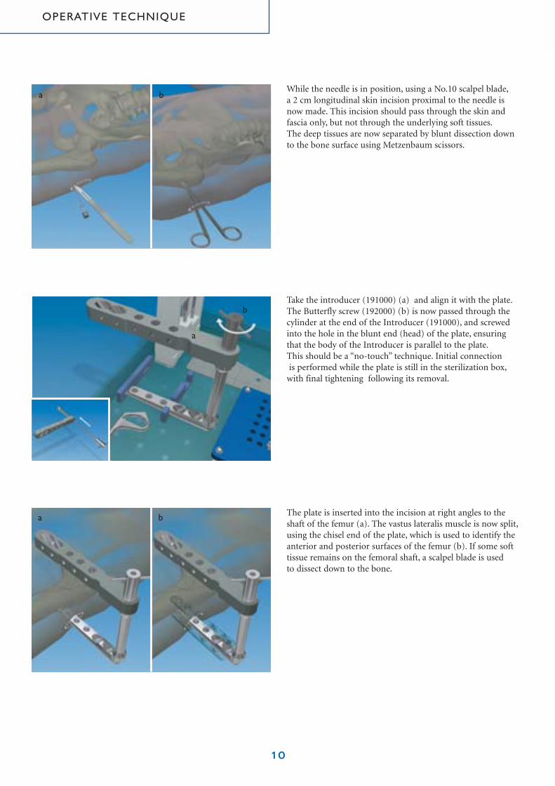
While the needle is in position, using a No.10 scalpel blade,a 2 cm longitudinal skin incision proximal to the needle isnow made. This incision should pass through the skin andfascia only, but not through the underlying soft tissues.The deep tissues are now separated by blunt dissection downto the bone surface using Metzenbaum scissors.
Take the introducer (191000) (a) and align it with the plate.The Butterfly screw (192000) (b) is now passed through thecylinder at the end of the Introducer (191000), and screwedinto the hole in the blunt end (head) of the plate, ensuringthat the body of the Introducer is parallel to the plate.This should be a “no-touch” technique. Initial connectionis performed while the plate is still in the sterilization box,
with final tightening following its removal.
10
The plate is inserted into the incision at right angles to theshaft of the femur (a). The vastus lateralis muscle is now split,using the chisel end of the plate, which is used to identify theanterior and posterior surfaces of the femur (b). If some softtissue remains on the femoral shaft, a scalpel blade is used to dissect down to the bone.
b
a
a b
a b
OPERATIVE TECHNIQUE
11
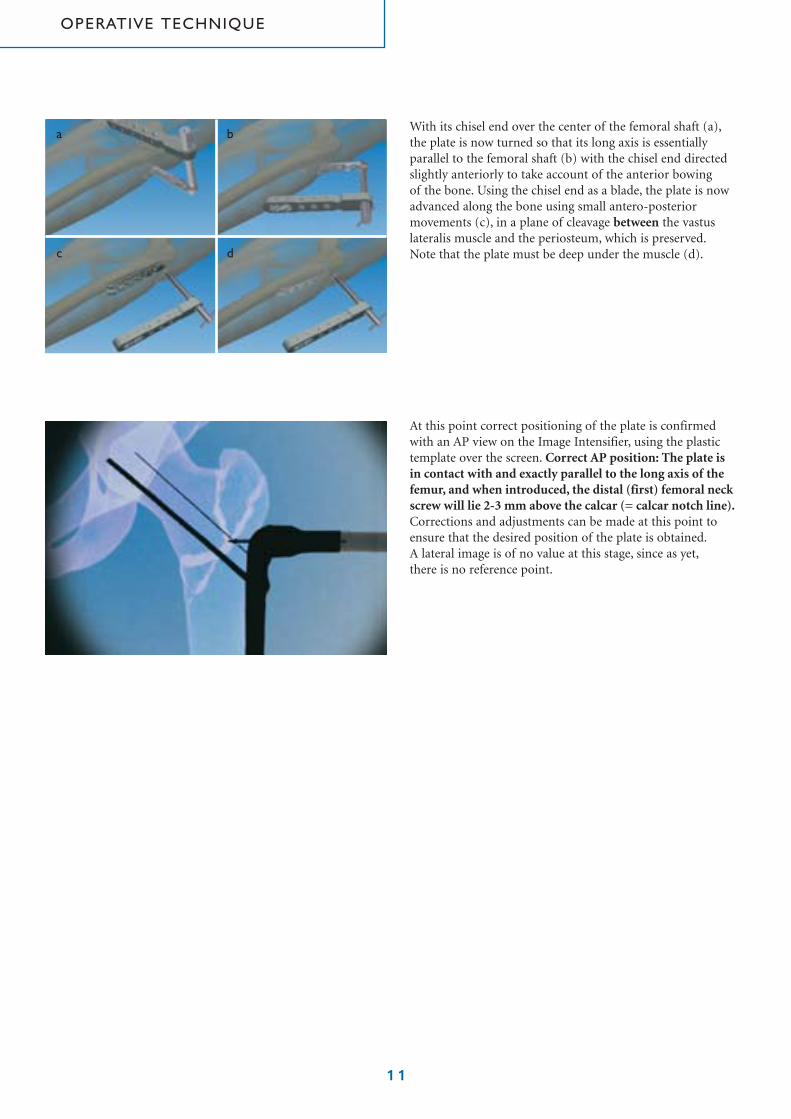
With its chisel end over the center of the femoral shaft (a),the plate is now turned so that its long axis is essentiallyparallel to the femoral shaft (b) with the chisel end directedslightly anteriorly to take account of the anterior bowing of the bone. Using the chisel end as a blade, the plate is nowadvanced along the bone using small antero-posteriormovements (c), in a plane of cleavage between the vastuslateralis muscle and the periosteum, which is preserved.Note that the plate must be deep under the muscle (d).
At this point correct positioning of the plate is confirmedwith an AP view on the Image Intensifier, using the plastictemplate over the screen. Correct AP position: The plate is in contact with and exactly parallel to the long axis of thefemur, and when introduced, the distal (first) femoral neckscrew will lie 2-3 mm above the calcar (= calcar notch line).Corrections and adjustments can be made at this point toensure that the desired position of the plate is obtained.A lateral image is of no value at this stage, since as yet,there is no reference point.
a b
c d
OPERATIVE TECHNIQUE
12
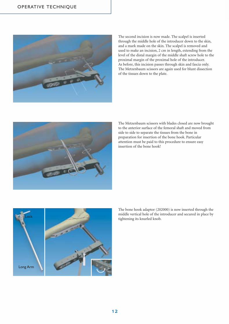
The second incision is now made. The scalpel is insertedthrough the middle hole of the introducer down to the skin,and a mark made on the skin. The scalpel is removed andused to make an incision, 2 cm in length, extending from thelevel of the distal margin of the middle shaft screw hole to theproximal margin of the proximal hole of the introducer.As before, this incision passes through skin and fascia only.The Metzenbaum scissors are again used for blunt dissectionof the tissues down to the plate.
The Metzenbaum scissors with blades closed are now broughtto the anterior surface of the femoral shaft and moved fromside to side to separate the tissues from the bone inpreparation for insertion of the bone hook. Particularattention must be paid to this procedure to ensure easyinsertion of the bone hook!
The bone hook adaptor (202000) is now inserted through themiddle vertical hole of the introducer and secured in place bytightening its knurled knob.
Lock
Long Arm
OPERATIVE TECHNIQUE

13
The bone hook (207000) has two jaws, a distal (bone) jawwhich is curved to accept the medial aspect of the femur,and a flat proximal (plate) jaw to accept the plate. The hook is inserted through the second, distal incision, with its jawsclosed. It is introduced in the frontal plane at 45 degrees to the femoral shaft so that the short cutting front edge of the bone jaw will enter the incision first.
Once within the incision the bone hook is turned so that it is at 90 degrees to the shaft of the femur in the frontal plane,and advanced into the wound, keeping the handle (andtherefore the jaws) parallel to the introducer. The bone hookis now locked to the bone hook adaptor in this position.The correct AP position of the plate is confirmed with imageintensification at this stage to ensure that its position has notbeen disturbed. (lock and look).
The wing screw on the bone hook is now unscrewed fully.The outer handle of the bone hook can now be advanced with turning movements to push the distal (bone) jawmedially, anterior to the femoral shaft. It should be noted,however, that the outer handle can only engage the bone jawshaft when both are in the same plane.This is an importantfeature of the device since it provides information on the exactorientation of the bone jaw within the wound.
Bone Jaw
Plate Jaw
ForkedHandle
WingScrew
OuterHandle
M
OPERATIVE TECHNIQUE

14
The bone jaw only is now pushed medially (a) and turneddownwards (b) through 90 degrees to grasp the femur firmly,keeping the jaw in contact with the bone throughout. This canbe accomplished without the need for an X-ray.Note: the orientation of the handle shows the position of the jaw.
The plate jaw handle is now withdrawn until the M-line justdisappears within the bone hook adaptor.This indicates that the plate jaw has cleared the plate; it is nowrotated downwards through 90 degrees so that it can grasp it.Both bone hook handles are now stabilized with the long armof the bone hook adaptor (a). The jaws of the bone hook arenow slightly tightened with the wing screw.
The position of the plate is now checked under lateral imageintensification. If it is correct, the head of the plate will be in line with the femoral neck and the tail of the plate will liealong the femoral shaft. If a lateral view indicates thatcorrection is needed, this can be made by twisting movementsof the head and tail of the plate (the bone hook pivots) or by pulling the plate posteriorly (the bone hook glides and maintains the AP position). Check the AP position.
When both the AP and lateral position of the plate issatisfactory, the jaws of the bone hook are finally tightenedwith the wing screw to clamp the plate firmly to the bone.
a
a
M
b
OPERATIVE TECHNIQUE

15
The main sleeve (195000) (a) and neck trocar (198000) (b) are now introduced through the most distal oblique hole of the introducer.This process is facilitated using the skinretractor (c) provided. The main sleeve is now locked intoposition with a bolt (d) inserted throught the introducer.The trocar is withdrawn.
The first neck sleeve (196000) is identified by a singlecircumferential line around the head. It is inserted into the main sleeve and screwed into the plate. Any difficulty inachieving this may be due to soft tissue interposition, in whichcase the neck sleeve should be removed and the neck trocarreinserted and turned around to clear a path to the plate.The first neck sleeve is then reintroduced.
The main guide (189000Q) is now inserted into the firstsleeve and drilled into the bone.
a
b
d
c
OPERATIVE TECHNIQUE
16
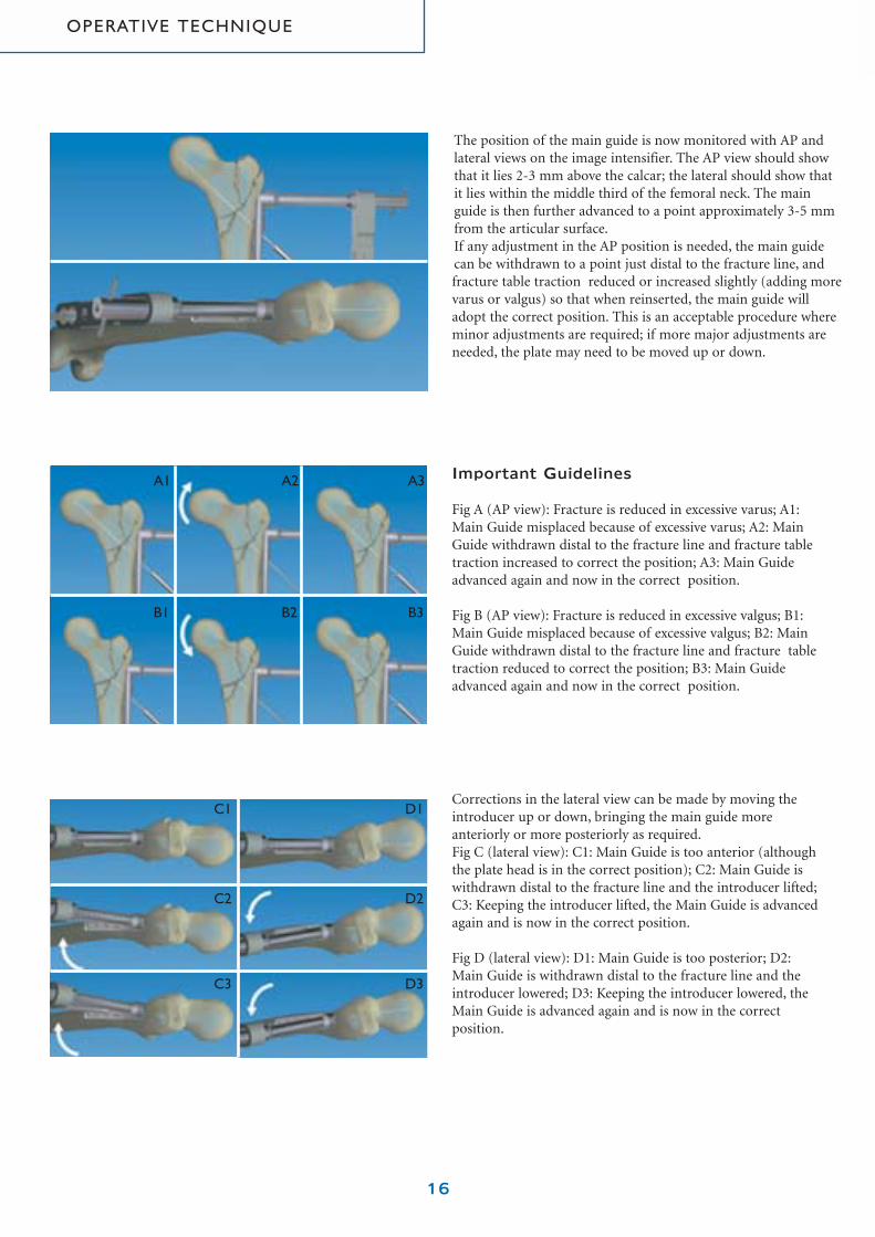
Important Guidelines
Fig A (AP view): Fracture is reduced in excessive varus; A1:Main Guide misplaced because of excessive varus; A2: MainGuide withdrawn distal to the fracture line and fracture tabletraction increased to correct the position; A3: Main Guideadvanced again and now in the correct position.
Fig B (AP view): Fracture is reduced in excessive valgus; B1:Main Guide misplaced because of excessive valgus; B2: MainGuide withdrawn distal to the fracture line and fracture tabletraction reduced to correct the position; B3: Main Guideadvanced again and now in the correct position.
Corrections in the lateral view can be made by moving theintroducer up or down, bringing the main guide moreanteriorly or more posteriorly as required.Fig C (lateral view): C1: Main Guide is too anterior (althoughthe plate head is in the correct position); C2: Main Guide iswithdrawn distal to the fracture line and the introducer lifted;C3: Keeping the introducer lifted, the Main Guide is advancedagain and is now in the correct position.
Fig D (lateral view): D1: Main Guide is too posterior; D2:Main Guide is withdrawn distal to the fracture line and theintroducer lowered; D3: Keeping the introducer lowered, theMain Guide is advanced again and is now in the correctposition.
The position of the main guide is now monitored with AP andlateral views on the image intensifier. The AP view should showthat it lies 2-3 mm above the calcar; the lateral should show that it lies within the middle third of the femoral neck. The mainguide is then further advanced to a point approximately 3-5 mmfrom the articular surface.If any adjustment in the AP position is needed, the main guidecan be withdrawn to a point just distal to the fracture line, andfracture table traction reduced or increased slightly (adding morevarus or valgus) so that when reinserted, the main guide willadopt the correct position. This is an acceptable procedure whereminor adjustments are required; if more major adjustments areneeded, the plate may need to be moved up or down.
A1
B1 B2 B3
A2 A3
C1
C2
C3
D1
D2
D3
OPERATIVE TECHNIQUE

The length of main guide remaining outside, between itsshoulder and the first neck sleeve, is a measure of the length of the neck screw required. This can be measured as shown,using the gauge (199000) with its square edge adjacent to thehead of the first neck sleeve, and the oblique edge against theshoulder. The space over which the projecting portion of themain guide lies is marked with the length of screw required.
The main guide and first neck sleeve are now removed,and the second neck sleeve (197000) (identified by twocircumferential lines around the head) introduced into the main sleeve and screwed to the plate.
17
35A
Once the position of the Main Guide is correct on both APand lateral views, the butterfly pin (193000Q) is inserted intothe butterfly screw and drilled into the bone, all the way to thestop (a). This provides two point fixation of the plate to thefemoral shaft.
With a very unstable fracture, additional stabilization may be provided by means of a fixation wire which is insertedthrough one of the accessory holes (b) in the introducer for a distance of 2-3 mm into the acetabulum. This must be doneunder lateral image intensification.
a
b
OPERATIVE TECHNIQUE

18
The correct length neck screw is now attached to the NeckScrewdriver (184000). This instrument has:1. An inner shaft (a) activated by Grip 3. This has a threaded
end which engages the neck screw head.2. An outer shaft (b) activated by Grip 1, which screws
the outer barrel of the neck screw to the plate.3. A middle shaft (c) activated by Grip 2. This shaft has a
hexagonal end for screwing the neck screw into the bone.4. A Nut, for compression of the fracture.5. Two Buttons D and E to release and separate the handle
for cleaning.
Grip 1
Grip 2
Grip 3
D
Nut
E
The 9.3 mm drill bit (187000Q) is now inserted into the mainsleeve and drilled to its stop (a). Care should be taken toensure that the direction of drilling follows the path taken bythe main guide. If necessary, this may require the introducerto be raised or lowered slightly. Ideally, drilling with the 7mm and 9.3 mm drill bits should be performed under lateralimage intensification. This will enable any corrections neededto centralize the drill to be made during the procedure.
The 7 mm drill bit (186000Q) is now inserted into the secondneck sleeve and drilled up to its stop. The direction of drillingshould follow the corrected position of the Main Guide. Thisshould be monitored under lateral image intensification.The 7 mm drill bit and the second neck sleeve are nowwithdrawn.
a
c
b
a
OPERATIVE TECHNIQUE

If the neck screws are correctly loaded in their dispenser thehexagonal recess in each will be at the level of the head of thescrew barrel, ready for attachment to the Screwdriver.The nut “N” on the Screwdriver is turned until it is touchinggrip 2. This ensures that the hexagonal end of the Screwdriveris extended to its limit. The Screwdriver is now held verticallyand its hexagonal end engaged in the hexagonal recess of thescrew.Grip 3 is now pushed down and turned clockwise, applyinggentle pressure while turning, to engage the threaded recess in the screw head.
Grip 1 is now slid forward until the teeth of the Screwdriverare seated in the cutouts (a) of the screw barrel thread. Theteeth are locked in position by turning the nut “N” down togrip 1, keeping them aligned with the cutouts while doing so.Care should be taken not to overtighten as this may disturbthe alignment.
19
The selected neck screw, mounted on the Screwdriver, isintroduced into the main sleeve. Grip 1 is turned until thethread at the base of the screw barrel is completely screwedinto the plate. When the line marked “L” on the Screwdrivershaft reaches the head of the main sleeve, this indicates thatthe threads of the screw barrel are entering the plate.
N
L
a
Grip 2
Grip 1
Grip 1
OPERATIVE TECHNIQUE
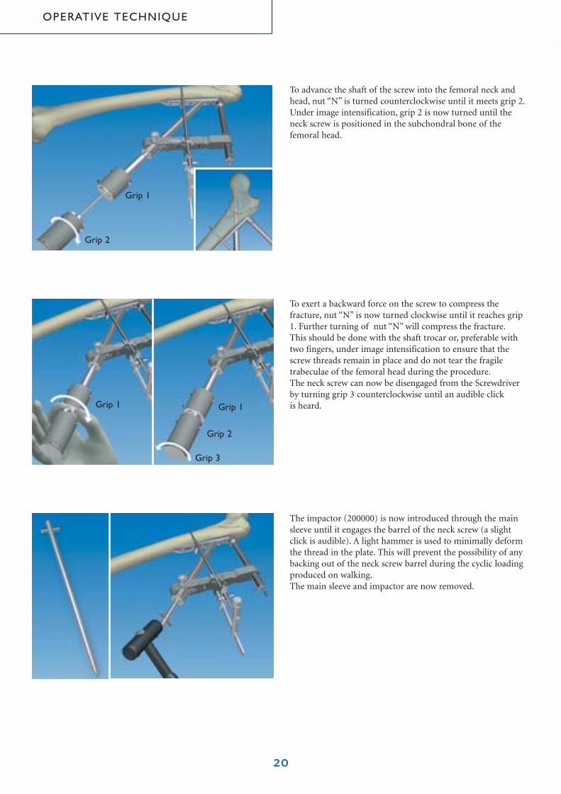
To advance the shaft of the screw into the femoral neck andhead, nut “N” is turned counterclockwise until it meets grip 2.Under image intensification, grip 2 is now turned until theneck screw is positioned in the subchondral bone of thefemoral head.
20
The impactor (200000) is now introduced through the mainsleeve until it engages the barrel of the neck screw (a slightclick is audible). A light hammer is used to minimally deformthe thread in the plate. This will prevent the possibility of anybacking out of the neck screw barrel during the cyclic loadingproduced on walking.The main sleeve and impactor are now removed.
To exert a backward force on the screw to compress thefracture, nut “N” is now turned clockwise until it reaches grip1. Further turning of nut “N” will compress the fracture.This should be done with the shaft trocar or, preferable withtwo fingers, under image intensification to ensure that thescrew threads remain in place and do not tear the fragiletrabeculae of the femoral head during the procedure.The neck screw can now be disengaged from the Screwdriverby turning grip 3 counterclockwise until an audible click is heard.
Grip 1
Grip 1 Grip 1
Grip 2
Grip 2
Grip 3
OPERATIVE TECHNIQUE

21
The shaft sleeve (203000) and shaft trocar (204000Q) are nowinserted through either the proximal or distal vertical hole of the introducer using the small skin retractor to assist entryinto the incision.
The shaft sleeve is locked into position with a bolt (194000)inserted through the introducer, and the shaft trocar withdrawn.
Note that the shaft trocar has three additional functions:1. A triangular hole for attachment to the shaft Screwdriver
if manual application of the shaft screws is desired.2. A cylindrical protrusion to assist in turning the grips
of the neck Screwdriver.3. A short Screwdriver for the neck screw barrel.
The 3.2 mm step drill bit is now used to predrill the bone.
1
2
3
OPERATIVE TECHNIQUE

48B
The depth gauge (205000) is used to measure the length of bone screw required.It is introduced through the predrilled track and withdrawnuntil its hook engages the outer medial surface of the femur.The number which is now adjacent to the edge of the shaftsleeve head corresponds to the length of shaft screw required.
22
The correct length shaft screw is now attached to the shaftScrewdriver (185000Q) using gentle pressure. Note that theend of this Screwdriver is spring-loaded to grip the screwfirmly for insertion or removal.
A power tool is normally used for insertion of the shaftscrews. In this case insertion should be performed in stages,while listening carefully to the sound of the instrument toavoid stripping the thread in the bone. Where manualinsertion is preferred, the triangular recess in the head of theshaft trocar is fitted over the end of the shaft Screwdriver.In osteoporotic bone it is recommended that the shaft screwsare inserted manually.
OPERATIVE TECHNIQUE

23
The bone hook is now removed by simply reversing the stepsused for its insertion.The butterfly pin must now be removed.The remaining two shaft screws are now inserted as describedabove, followed by the second (proximal) neck screw.This neck screw is also inserted using the main guide in orderto measure the length of screw required. Following screwintroduction, the barrel is impacted to minimally deform the thread in the plate as before.
The introducer is now unlocked (butterfly screw) andremoved.
The wound is now irrigated, and a suction drain left in situ for twenty four hours. The subcutaneous tissues and skin areclosed in the normal manner and a full length elastic bandageor stocking applied to the lower extremity.
OPERATIVE TECHNIQUE

Post-operatively, full weightbearing may be allowedimmediately, initially with a walking frame and subsequentlywith crutches.
24
POST- OPERATIVE MANAGEMENT

Orthofix wishes to thank
Dr. Y. Gotfried, MD, MS
for his invaluable helpin the preparation of this manual

Your Distributor is:
ORTHOFIX - Wonersh House - The Guildway - Old Portsmouth RoadGuildford - Surrey GU3 1LR - England
Tel. 44 1483 468800 Fax 44 1483 468829
www.orthofix.com
PM PCP E0 04B-01/04GF-0401(A)-OPT-E0


![TRANSORAL SURGERY - Department of …. Product Description Catalog No. Manufacturer ... 1 Regular Metzenbaum 7" Scissor 54-1027 Codman 1 8" [Long Suture] Sims Scissor 54-5503 Codman](https://static.fdocuments.net/doc/165x107/5ae2df4e7f8b9a5d648d35b7/transoral-surgery-department-of-product-description-catalog-no-manufacturer.jpg)

