The Frontal Plane QRS Loop in the Normal Heart and in Diaphragmatic Myocardial Infarction
9
JULY 13, 1963 * VOL. 89, NO. 2 HARRY ABRAMSON, M.D.,* Toronto I T HAS been accepted by most workers in the field that the vectorcardiogram gives more in- formation about the heart's electrical activity than does the electrocardiogram. It is the purpose of this paper to reaffirm this concept by discussing in de- tail the frontal plane QRS loops of a series of young subjects with normal hearts and comparing these to the corresponding loops of a group of patients with diaphragmatic myocardial infarction. Although con- siderable work has already been done in describing the normal vectorcardiogram, little of this has in- volved the use of the Frank lead system.1-3 Since this is the technique currently being used in this laboratory, it was felt that a report of our findings in the normal heart might prove of value. Abnormalities of the QRS loop alone are specific in transmural myocardial infarction. Criteria for diagnosis of such abnormalities in diaphragmatic infarction have been described previously, but these have usually been qualitative rather than quanti- tative.4' . Wolff6 has measured the maximal initial superior vector, making use of the Duchosal trihed- ron reference system. He feels that diaphragmatic infarction can be diagnosed when initial or early superior forces in the frontal plane exceed .12 my. or when the superior/inferior ratio exceeds .13 when the sweep is clockwise. Rather than the maximal initial superior vector, we have chosen to define the .02-second vector. Infarction involving the diaphragmatic surface of the heart is associated with a loss of initial inferior forces, the .02-second vector being abnormally elevated and usually of increased magnitude. Vector forces acting in an anteroposterior direction are not affected. The horizontal plane QRS loop does not deviate from the normal. Only frontal and sagittal plane QRS abnormalities result. However, changes in the former are adequately specific to allow vector From the Cardlo-Pulmonary Laboratory, New Mount Sinai Hospital, Toronto. Research Associate, Department of Medicine, New Mount Sinai Hospital, Toronto. ABSTRACT The efferent limb of the frontal plane QRS loop of the vectorcardiogram was studied quantitatively in 100 normal subjects and in 50 patients with electrocardiographic QRS evidence of diaphragmatic infarction. Ef- ferent limb analysis consisted of determina- tion of the position of the .02-second and maximal vectors in the triaxial reference frame and of the ratio born by the magni- tude of the .02-second vector to that of the maximal vector. This ratio was not found to be greater than 0.16 in the normal heart with clockwise loop inscription and a superiorly dfrected .02-second vector. When 20 patients with only ST-T changes of dia- phragmatic infarction in the electrocardio- gram were similarly studied, 13 showed sig- nificant QRS loop evidence of this infarc- tion.
description
An Analysis of the Frontal Plane QRS loop in the normal heart with regard to vector cardiographic studies.
Transcript of The Frontal Plane QRS Loop in the Normal Heart and in Diaphragmatic Myocardial Infarction

JULY 13, 1963 * VOL. 89, NO. 2
HARRY ABRAMSON, M.D.,* Toronto
IT HAS been accepted by most workers in thefield that the vectorcardiogram gives more in-
formation about the heart's electrical activity thandoes the electrocardiogram. It is the purpose of thispaper to reaffirm this concept by discussing in de-tail the frontal plane QRS loops of a series of youngsubjects with normal hearts and comparing these tothe corresponding loops of a group of patients withdiaphragmatic myocardial infarction. Although con-siderable work has already been done in describingthe normal vectorcardiogram, little of this has in-volved the use of the Frank lead system.1-3 Sincethis is the technique currently being used in thislaboratory, it was felt that a report of our findingsin the normal heart might prove of value.
Abnormalities of the QRS loop alone are specificin transmural myocardial infarction. Criteria fordiagnosis of such abnormalities in diaphragmaticinfarction have been described previously, but thesehave usually been qualitative rather than quanti-tative.4' . Wolff6 has measured the maximal initialsuperior vector, making use of the Duchosal trihed-ron reference system. He feels that diaphragmaticinfarction can be diagnosed when initial or earlysuperior forces in the frontal plane exceed .12 my.or when the superior/inferior ratio exceeds .13 whenthe sweep is clockwise. Rather than the maximalinitial superior vector, we have chosen to define the.02-second vector.
Infarction involving the diaphragmatic surface ofthe heart is associated with a loss of initial inferiorforces, the .02-second vector being abnormallyelevated and usually of increased magnitude. Vectorforces acting in an anteroposterior direction are notaffected. The horizontal plane QRS loop does notdeviate from the normal. Only frontal and sagittalplane QRS abnormalities result. However, changesin the former are adequately specific to allow vector
From the Cardlo-Pulmonary Laboratory, New Mount SinaiHospital, Toronto.Research Associate, Department of Medicine, New Mount
Sinai Hospital, Toronto.
ABSTRACT
The efferent limb of the frontal plane QRSloop of the vectorcardiogram was studiedquantitatively in 100 normal subjects and in50 patients with electrocardiographic QRSevidence of diaphragmatic infarction. Ef-ferent limb analysis consisted of determina-tion of the position of the .02-second andmaximal vectors in the triaxial referenceframe and of the ratio born by the magni-tude of the .02-second vector to that of themaximal vector. This ratio was not found tobe greater than 0.16 in the normal heartwith clockwise loop inscription and asuperiorly dfrected .02-second vector. When20 patients with only ST-T changes of dia-phragmatic infarction in the electrocardio-gram were similarly studied, 13 showed sig-nificant QRS loop evidence of this infarc-tion.
48 ABRAMSON: FRONTAL PLANE QRS Loon Canad. Med. Ass. J.July 13, 1963, vol. 89
o CLOCKWISE
* COUNTERCLOCKWISE
£ FIGURE-OF-EIGHT OR ED(.
&
H'4
00.0Co
0
0.
0 00
a I I0
- 1.00
-'.90
- .80
r.6O
.50
0
- .40- .30
.20
. .10
00
I K U I
-1.0 -130 -80 -60 ..4Q 0
A
00
0o * 0o .00 0
I A0b%.0..o
A 00 00 %.. . 0 OP
0
20 40 60 80 100
.02 6econd vector (an.1e)
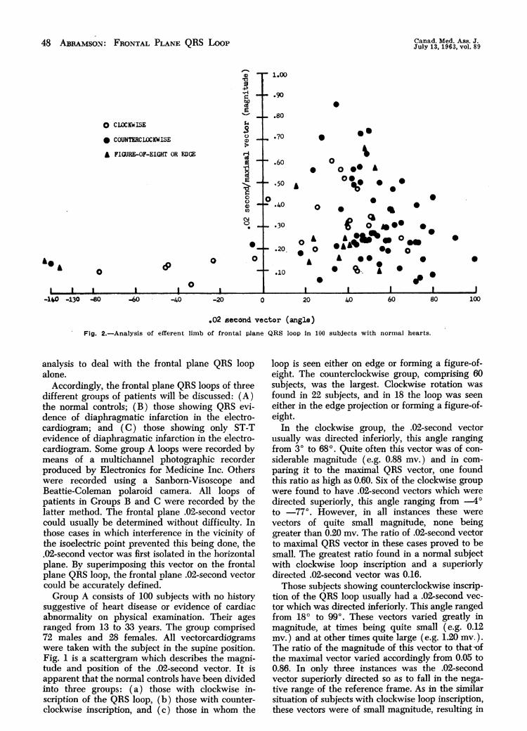
Fig. 2.-Analysis of efferent limb of frontal plane QRS loop in 100 subjects with normal hearts.
analysis to deal with the frontal plane QRS loopalone.
Accordingly, the frontal plane QRS loops of threedifferent groups of patients will be discussed: (A)the normal controls; (B) those showing QRS evi-dence of diaphragmatic infarction in the electro-cardiogram; and (C) those showing only ST-Tevidence of diaphragmatic infarction in the electro-cardiogram. Some group A loops were recorded bymeans of a multichannel photographic recorderproduced by Electronics for Medicine Inc. Otherswere recorded using a Sanborn-Visoscope andBeattie-Coleman polaroid camera. All loops ofpatients in Groups B and C were recorded by thelatter method. The frontal plane .02-second vectorcould usually be determined without difficulty. Inthose cases in which interference in the vicinity ofthe isoelectric point prevented this being done, the.02-second vector was first isolated in the horizontalplane. By superimposing this vector on the frontalplane QRS loop, the frontal plane .02-second vectorcould be accurately defined.Group A consists of 100 subjects with no history
suggestive of heart disease or evidence of cardiacabnormality on physical examination. Their agesranged from 13 to 33 years. The group comprised72 males and 28 females. All vectorcardkigramswere taken with the subject in the supine position.Fig. 1 is a scattergram which describes the magni-tude and position of the .02-second vector. It isapparent that the normal controls have been dividedinto three groups: (a) those with clockwise in-scription of the QRS loop, (b) those with counter-clockwise inscription, and (c) those in whom the
loop is seen either on edge or forming a figure-of-eight. The counterclockwise group, comprising 60subjects, was the largest. Clockwise rotation wasfound in 22 subjects, and in 18 the loop was seeneither in the edge projection or forming a figure-of-eight.
In the clockwise group, the .02-second vectorusually was directed inferiorly, this angle rangingfrom 30 to 68g. Quite often this vector was of con-siderable magnitude (e.g. 0.88 my.) and in com-paring it to the maximal QRS vector, one foundthis ratio as high as 0.60. Six of the clockwise groupwere found to have .02-second vectors which weredirected superiorly, this angle ranging from .4oto ..77o. However, in all instances these werevectors of quite small magnitude, none beinggreater than 0.20 my. The ratio of .02-second vectorto maximal QRS vector in these cases proved to besmall. The greatest ratio found in a normal subjectwith clockwise loop inscription and a superiorlydirected .02-second vector was 0.16.Those subjects showing counterclockwise inscrip-
tion of the QRS loop usually had a .02-second vec-tor which was directed inferiorly. This angle rangedfrom 180 to 990, These vectors varied greatly inmagnitude, at times being quite small (e.g. 0.12my.) and at other times quite large (e.g. 1.20 my.).The ratio of the magnitude of this vector to that -ofthe maximal vector varied accordingly from 0.05 to0.86. In only three instances was the .02-secondvector superiorly directed so as to fall in the nega-tive range of the reference frame. As in the similarsituation of subjects with clockwise loop inscription,these vectors were of small magnitude, resulting in

ABRAM5ON: FRONTAL PLANE QRS Loon 49
TABLE 1.- SLMMAR. us FRONIAL PLANE MEAN \ALLI.5 IN100 NORMAL SUBJECTS
No. of QRS loop.subjects inscription
22 Clockwise60 Counter-clock" i.7 Edge
11 Figure-of eight100
02-scrond vector(mean)
Degrees AlL
18 .36H 47 .43
49 .4812 .3737 .42
Maximal vector R(mean)
Degrees AlL
48 1.3142 1.3053 1.5843 14744 1.46
Ratio of.02-secondrector R
.27
.32
.32
.26
.30
small .02-second to maximal vector ratios, thelargest of the three ratios being 0.22.
Eleven of the 100 normal subjects presented afigure-of-eight pattern in the frontal plane. Ofthese, only t.vo showed a superiorly directed .02-second vector, i.e. -136. and .143o. In both in-stances, the .02-second to maximal vector ratio wassmall, 0.12 and 0.15, respectively. In both instancesthe initial segment of the figure-of-eight loop wasinscribed in a counterclockwise direction.
Seven subjects presented with the edge projectionin the frontal plane. In all seven, the .02-secondvector was inferiorly directed. The relationship be-tween the angle of the .02-second vector and theratio borne by the magnitude of this vector to thatof the maximal vector is plotted in Fig. 2. Table Isummarizes our findings in these control subjects.Group B consists of 50 patients with unequivocal
QRS evidence of diaphragmatic infarction in theelectrocardiogram. In each instance, the electro-cardiogram showed Q waves in leads 3 and aVFwhich were .03 second or greater in duration, andat least 25% of the height of the succeeding Rwave. Some of the infarcts were recent, and somewere old so that ST-T changes of infarction .verenot necessarily present.
-90
o 000
'C00£
±180
0 CLOCKWISE
* COUNTERCLOCKWISE
£ PIBJRE-OF-EIGHT
0
o. 0
000 £
oaOe .
o 0 00
0S
0£00
£0
0 0
0
.1 my.
90Fig. 3.-Position and magnitude of .02-second frontal vector
in su patients with QRS evidence of diaphragmatic infarctionin the electrocardiogram.
The most common type of ioop was that of clock-.vise inscription, present in 38 cases. A figure-of-eight with the initial segment of the loop inscribedin a clockwise direction was present in 10 patients.A counterclockwise superiorly situated loop was
TABLE I1.-Sr-.n¶ARY OF FRONTAL PL4NE MEAN X4LUES IN30 PATIENTS WITH DIAPHR4GMATIC INFARCTION
No. of QRS looppatients inscription
38 Clockwise10 Figure-of eight2 Counter-clockwise
30
.02-second rector(InentI)
Degrees .1II..
5.3 .42.J.) .37
67 .5954 .41
Maximal t ector R Ratio of(mean) .02-second
Degrees M F. vector R
11 1.14 .4116 1.11 .3571 .70 .852 1.12 .42
00
0
0& 0
0
& 0
0
0 0 0
& 0000
00
I
00
0
£& Oh
0o0
I0
A
0I-100
r-80 -60 -40 -20 0
1.00
0.90 h)
to
C)00-
9'*.709'
.60 i-'C)C)
..50 '1
..40f-i.
.30 .0 o-
.20
- .10
20 40
o CLOCKWLSE
* COUNTERCLOCKWISE
& FIGURE-OF-EIGHT
.0
Canad. Med. Ass. J.July 13, 1963, vol. 89
0
&0
I-120
.02 second vector (angle)Fig. 4.-Analysis of efferent limb of frontal plane QRS loop in 30 patients with diaphragmatic infarction.

50 ABRAMSON: FRONTAL PIA. QRS Loot Canad. Med. Ass. J.July 13, 1963, vol. 89
part of the eight clockwise; and of these, 46 showeda superior .02-second vector. Only four of this lattergroup of 46 patients had a ratio of .02-secondvector to maximal vector which was equal to or lessthan .16, i.e. the upper limit in the normal controls.But the .02-second vector was abnormally elevatedto .1O3O in one of these four patients. In the otherthree, although this vector was found at .350,
490 and -78., the maximal vector was moresuperiorly directed than in the normal, resulting inan elevation of the entire efferent limb of the QRSloop. In our normal subjects .vith clockwise loops,the maximal vector was always directed inferiorlyand to the left, even though the .02-second vectormight be directed superiorly. In those subjects witha superior .02-second vector, the maximal vectorwas never found to be less than 350. Usually it wasmuch greater than this, viz. 560, 600, . In thethree patients under discussion, the maximal vectorwas situated at .30, 40 and 9o. I. must be pointedout, however, that such an elevated maximal vectorwas not an invariable finding in the group Bpatients. The mean maximal vector in the 50 pa-tients was 20, but one did see a maximal vector asinferiorly directed as 610.
Fig. 5.-Electrocardiogram showing ST segment coving,inverted T waves and deep Q waves of .03 second's durationin leads 2, 3 and aVF.
present in two. Regardless of the pattern, the .02-second vector was almost invariably superiorlysituated. In only two of the 50 cases was this nottrue, these two vectors being found at QO and 100,respectively. The degree of elevation of this vectorwas usually quite considerable. It ranged from .....30to .110o, the mean angle for the entire group of50 patients being .540. This, of course, is wellsuperior to the mean of 370 for the .02-secondvector in our normal subjects. The mean for the 22normal subjects with clockwise loop inscription was180.The magnitude of the .02-second vector was
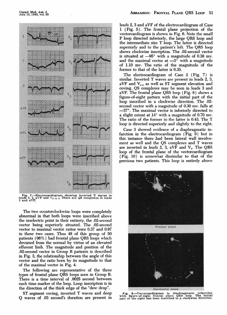
quite variable; however, it bore a much differentrelationship to the maximal vector than it did inthe normal. In the normal heart with clockwise loopinscription, only six subjects showed a superiorlydirected .02-second vector. This vector was alwayssmall compared to the maximal vector, so that theratio of the former to the latter varied from .04 to.16. In the group of 50 infarcts, 48 presented witha clockwise or figure-of-eight loop with the initial Fig. 6.-Vectorcardiogram in diaphragmatic infarction
with clockwise frontal plane QBS loop.
Canad. Med. Ass. J.July 13,1963, vol. 89 Abramson: Frontal Plane QRS Loop 51
I
."21
aVR
aVI
aVF
lllllitiH fiifeSm fff*
mmsmsm
Fig. 7..Electrocardiogram showing inverted T waves inleads 2, 3, aVF and V3, 4, 5. There are QS complexes in leads3 and aVF.
The two counterclockwise loops were completelyabnormal in that both loops were inscribed abovethe isoelectric point in their entirety, the .02-secondvector being superiorly situated. The .02-secondvector to maximal vector ratios were 0.37 and 0.97in these two cases. Thus 48 of this group of 50patients (96%) had frontal plane QRS loops whichdeviated from the normal by virtue of an elevatedefferent limb. The magnitude and position of the.02-second vector in Group B patients is describedin Fig. 3, the relationship between the angle of thisvector and the ratio born by its magnitude to thatof the maximal vector in Fig. 4.The following are representative of the three
types of frontal plane QRS loops seen in Group B.There is a time interval of .0025 second betweeneach time marker of the loop. Loop inscription is inthe direction of the thick edge of the "dew drop".ST segment coving, inverted T waves and deep
Q waves of .03 second's duration are present in
leads 2, 3 and aVF of the electrocardiogram of Case1 (Fig. 5). The frontal plane projection of thevectorcardiogram is shown in Fig. 6. Note the smallP loop directed inferiorly, the large QRS loop andthe intermediate size T loop. The latter is directedsuperiorly and to the patient's left. The QRS loopshows clockwise inscription. The .02-second vectoris situated at .95° with a magnitude of 0.38 mv.and the maximal vector at .5° with a magnitudeof 1.10 mv. The ratio of the magnitude of theformer to that of the latter is 0.35.The electrocardiogram of Case 2 (Fig. 7) is
similar. Inverted T waves are present in leads 2, 3,aVF and V3.5 as well as ST segment elevation andcoving. QS complexes may be seen in leads 3 andaVF. The frontal plane QRS loop (Fig. 8) shows a
figure-of-eight pattern with the initial part of theloop inscribed in a clockwise direction. The .02-second vector with a magnitude of 0.30 mv. falls at.37°. The maximal vector is inferiorly directed toa slight extent at 14° with a magnitude of 0.70 mv.
The ratio of the former to the latter is 0.43. The Tloop is directed superiorly and slightly to the right.Case 3 showed evidence of a diaphragmatic in-
farction in the electrocardiogram (Fig. 9) but inthis instance there bad been lateral wall involve-ment as well and the QS complexes and T waves
are inverted in leads 2, 3, aVF and V6. The QRSloop of the frontal plane of the vectorcardiogram(Fig. 10) is somewhat dissimilar to that of theprevious two patients. This loop is entirely above
Fig. 8..Vectorcardiogram in diaphragmatic infarctionwith figure-of-eight frontal plane QRS loop. The initialpart of the eight has been inscribed in a clockwise direction.

52 ABRAMSON: FRONTAL PLANE QRS Loon Canad. Med. Ass. J.July 13, 1963, vol. 89
Fig. 9.-Electrocardiogram showing QS complexes and in-verted T waves in leads 2, 3. aVF and V6.
the isoelectric point and inscribed in a counter-clockwise direction. i.e. the afferent limb of theloop is superior to the efferent. The .02-secondvector with a magnitude of 0.66 my. may be seenat .350, the maximal vector with a magnitude of0.68 my. at .400, the ratio of the former to thelatter being 0.97. The T loop is directed superiorlyand somewhat to the right.Group C consists of 20 patients with ST-T evi-
dence of diaphragmatic infarction in the electro-cardiogram. In no instance were there significant Q.vaves in leads 3 and aVF, so that the diagnosis ofnon-transmural infarction only was made electro-cardiographically.The frontal plane QRS loop showed a clockwise
pattern in 13 of the patients, counterclockwise inthree, and a figure-of-eight in four. The .02-secondvector was superiorly directed in 10 of the clock-wise loops, this angle ranging from .9O to .105..When the .02-second vector was compared to themaximal vector, it was found that the ratio of themagnitude of the former to that of the latter wasgreater than the upper limit of normal in ourcontrol subjects in six natients. In these, the ratio
Fig. 1 0.-Vectorcardiogram in diaphragmatic infarctionwith superiorly situated counterclockwise frontal plane QRSloop.
varied between 0.18 and 0.41. Although a seventhpatient had a ratio of 0.16, the .02-second vectorwas elevated to .880. We concluded that this wasabnormal, since .770 was the upper limit for the.02-second vector in a clockwise loop in the controlsubjects. As well, three of the Group C patientswith a clockwise QRS loop and a superior .02-second vector showed maximal vectors less than 350,viz. 270, 260 and 210, so that there was abnormalelevation of the efferent limb of the loop.
o CL0CKW.E
* COUNT.L.CK.J$K
£ PIWRE-OP-ItgIT
a a
00 0
£
90
Fig. 11.-Position and magnitude of .02-second frontalvector in 20 patients with ST-T evidence of diaphragmaticinfarction in the electrocardiogram.

Canad. Med. Ass. .* ABRAMSON: FRONTAL PLANE QRS Loon 53July 13, 1963, vol. 89
*0
'. 1.00
. Ao CLOCKWISE
UV
* COUNTERCLOCKWISE . .80 A.. 0
£ F'IQJRE-OF-EIGHT U .70U*0cg .60
0:N
O .50 0
00 0 .40
0o .30 0
0 A .20
0 0 00 0 &.10
I I I I I I I I-100 -80 40 -40 -20 0 20 40 60 80 100
.02 second vector (angle)Fig. 12.-Analysis of efferent limb of frontal plane QRS loop in 20 pati6nts with ST-T
evidence of diaphragmatic infarction.
Two of the four patients with figure-of-eightloops showed similar elevation of the efferent limb.In each instance, the limb was concave inferiorly,the .02-second vector falling at .5O and .27o. themaximal vector at 140 and 80, respectively. In bothcases, the efferent limb started momentarily to theright and inferiorly, thus effectively masking the 2Q wave of infarction in the electrocardiogram.Of the three patients with counterclockwise loop
inscription, one showed a definite abnormality inthat the .02-second vector was elevated to -12.and bore a ratio of 0.56 to the maximal vector. Heretoo, the efferent limb was directed initially to the vright and inferiorly.
It was concluded that 13 (65%) of this group ...-.... ..'.'of 20 patients showed the same types of changes inthe frontal plane QRS loop of the vectorcardiogram "'as were found in those patients with unequivocal .QRS evidence of diaphragmatic infarction in theelectrocardiogram. Fig. 11 describes the .02-secondvector in group C. The relationship of the angle of .,this vector to the ratio of .02-second magnitudeto maximal vector magnitude may be seen inFig. 12. .The following are representative of Group C.
The electrocardiogram of patient 1 (Fig. 13) sho.vs V5inverted T waves and slight ST segment depressionin leads 2, 3, aVF and V6. There is an rS pattern aVF ;.:in lead 3 and an rSR' in lead aVF. Thus the 9 .wave of infarction is lacking. The frontal plane of -
6Fig. 13.-Electrocardiogram showing inverted T waves and
slight ST segment depression in leads 2, 3, aVF and V6. Thereis an rS pattern in lead 3 and an rSR1 in lead aVF.

54 ABRAMSON: FRONTAL PLANE QRS Loon Canad. Med. Ass. J.July 13, 1963, vol. 89

Canad. Med. Ass. J. ABRAMSON: FRONTAL PLANE QRS Loon 55July 13, 1963, vol. 89
L.1. VI
24:
V3
A
44. ....a.
I,
aVL.
AV5
aVP' .
Fig. 17.-Electrocardiogram showing T wave inversion inleads 2, 3, aVF and V5. o. Small R waves are present inleads 3 and aVF.
loop starts inferiorly and to the right. This wasnever seen in the group of normal subjects withfigure-of-eight ioops, for this pattern is a vector-cardiographic variant of diaphragmatic infarction.The electrocardiogram of patient 3 (Fig. 17) has
T wave inversion in leads 2, 3, aVF and V5-6. SmallR waves are present in leads 3 and aVF. The frontalplane vectorcardiogram (Fig. 18) shows anotherQRS variant of diaphragmatic infarction, i.e. acounterclockwise loop with both the efferent andafferent limbs concave inferiorly. The .02-secondvector at .12O and the maximal vector at -1'define an elevated efferent limb. The .02-second
Frontal plane
*
Horizontal plane
Fig. 18.-Vectorcardiogram with counterclockwise frontalplane QRS loop. Both the efferent and afferent limbs areconcave inferiorly.
vector is large for it bears a ratio of 0.56 to themaximal vector.
SUMMARY AND CONCLUSIONS
The frontal plane QRS loop of the vectorcardiogram(Frank lead system) has been described in a groupof 100 normal subjects and in a group of 50 patientswith QRS evidence of diaphragmatic infarction in theelectrocardiogram.
Emphasis has been placed on the efferent limb ofthe loop, as defined by the .02-second and maximalvectors.When a third group of 20 patients with only ST-T
evidence of diaphragmatic infarction in the electro-cardiogram were similarly studied, 13 (65%) showedsignificant QRS loop evidence of this infarction in thevectorcardiogram.
REFERENCES
1. FRANK, E.: Circulation, 13: 737, 1956.2. BRISTow, J. D.: Amer. Heart J., 61: 242, 1961.3. FORKNER, C. E., JR., HUGENHOLTZ, P. G. AND LEVINE, H.
D.: Ibid., 62: 237, 1961.4. BLTRCH, G. E. et al.: Circulation, 12: 418, 1955.5. MASsIE, E. AND WALSH, T. J.: Clinical vectorcardiography
and electrocardiography, Year Book Publishers, Inc.,Chicago, 1960.
6. WoLF!', L. et al.: Circulation, 23: 861, 1961.