THE FRINGING FIELD AND RESONANCE …khaledelleithy.org/Journals/Cylindrical Microstrip...THE...
12
THE FRINGING FIELD AND RESONANCE FREQUENCY OF CYLINDRICAL MICROSTRIP PRINTED ANTENNA AS A FUNCTION OF CURVATURE A. Elrashidi *, K. Elleithy * and Hassan Bajwa† *Department of Computer and Electrical Engineering † Department of Electrical Engineering University of Bridgeport, 221 University Ave, Bridgeport, CT, USA aelrashi@Bridgeport.edu ABSTRACT The fringing field has an important effect on the accurate theoretical modeling and performance analysis of microstrip patch antennas. Though, fringing fields effects on the performance of antenna and its resonant frequency have been presented before, effects of curvature on fringing field have not been reported before. The effective dielectric constant is calculated using a conformal mapping technique for a conformal substrate printed on a cylindrical body. Furthermore, the effect of effective dielectric constant on the resonance frequency of the conformal microstrip antenna is also studied. Experimental results are compared to the analytical results for RT/duroid-5880 PTFE substrate material. Three different substrate materials RT/duroid-5880 PTFE, K-6098 Teflon/Glass, and Epsilam-10 ceramic-filled Teflon are used for verifying the new model. KEYWORDS Fringing field, microstrip antenna, effective dielectric constant and Resonance frequency. 1. INTRODUCTION Due to the unprinted growth in wireless applications and increasing demand of low cost solutions for RF and microwave communication systems, the microstrip flat antenna, has undergone tremendous growth recently. Though the models used in analyzing microstrip structures have been widely accepted, the effect of curvature on dielectric constant and antenna performance has not been studied in detail. Low profile, low weight, low cost and its ability of conforming to curve surfaces [1], conformal microstrip structures have also witnessed enormous growth in the last few years. Applications of microstrip structures include Unmanned Aerial Vehicle (UAV), planes, rocket, radars and communication industry [2]. Some advantages of conformal antennas over the planer microstrip structure include, easy installation (randome not needed), capability of embedded structure within composite aerodynamic surfaces, better angular coverage and controlled gain, depending upon shape [3, 4]. While Conformal Antenna provide potential solution for many applications, it has some drawbacks due to bedding [5]. Such drawbacks include phase, impedance, and resonance frequency errors due to the stretching and compression of the dielectric material along the inner and outer surfaces of conformal surface. Changes in the dielectric constant and material thickness also affect the performance of the antenna. Analysis tools for conformal arrays are not mature and fully developed [6]. Dielectric materials suffer from cracking due to bending and that will affect the performance of the conformal microstrip antenna.
-
Upload
truongliem -
Category
Documents
-
view
237 -
download
3
Transcript of THE FRINGING FIELD AND RESONANCE …khaledelleithy.org/Journals/Cylindrical Microstrip...THE...
THE FRINGING FIELD AND RESONANCE FREQUENCY OF
CYLINDRICAL MICROSTRIP PRINTED ANTENNA AS A
FUNCTION OF CURVATURE
A. Elrashidi *, K. Elleithy * and Hassan Bajwa†
*Department of Computer and Electrical Engineering
† Department of Electrical Engineering
University of Bridgeport, 221 University Ave,
Bridgeport, CT, USA
ABSTRACT
The fringing field has an important effect on the accurate theoretical modeling and performance analysis of microstrip patch
antennas. Though, fringing fields effects on the performance of antenna and its resonant frequency have been presented
before, effects of curvature on fringing field have not been reported before. The effective dielectric constant is calculated
using a conformal mapping technique for a conformal substrate printed on a cylindrical body. Furthermore, the effect of
effective dielectric constant on the resonance frequency of the conformal microstrip antenna is also studied. Experimental
results are compared to the analytical results for RT/duroid-5880 PTFE substrate material. Three different substrate
materials RT/duroid-5880 PTFE, K-6098 Teflon/Glass, and Epsilam-10 ceramic-filled Teflon are used for verifying the new
model.
KEYWORDS
Fringing field, microstrip antenna, effective dielectric constant and Resonance frequency.
1. INTRODUCTION
Due to the unprinted growth in wireless applications and increasing demand of low cost solutions for RF and
microwave communication systems, the microstrip flat antenna, has undergone tremendous growth recently.
Though the models used in analyzing microstrip structures have been widely accepted, the effect of curvature on
dielectric constant and antenna performance has not been studied in detail. Low profile, low weight, low cost and
its ability of conforming to curve surfaces [1], conformal microstrip structures have also witnessed enormous
growth in the last few years. Applications of microstrip structures include Unmanned Aerial Vehicle (UAV),
planes, rocket, radars and communication industry [2]. Some advantages of conformal antennas over the planer
microstrip structure include, easy installation (randome not needed), capability of embedded structure within
composite aerodynamic surfaces, better angular coverage and controlled gain, depending upon shape [3, 4].
While Conformal Antenna provide potential solution for many applications, it has some drawbacks due to
bedding [5]. Such drawbacks include phase, impedance, and resonance frequency errors due to the stretching and
compression of the dielectric material along the inner and outer surfaces of conformal surface. Changes in the
dielectric constant and material thickness also affect the performance of the antenna. Analysis tools for conformal
arrays are not mature and fully developed [6]. Dielectric materials suffer from cracking due to bending and that
will affect the performance of the conformal microstrip antenna.
2. BACKGROUND
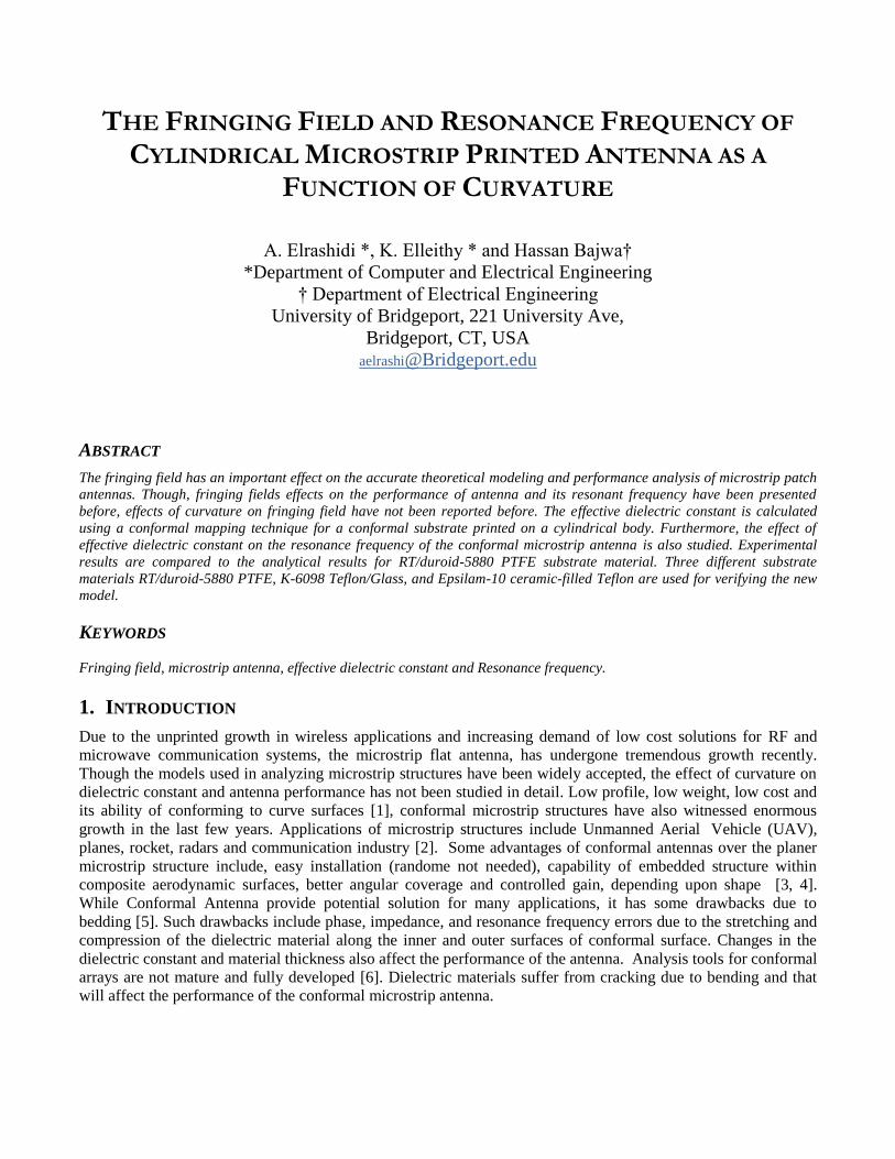
Conventional microstrip antenna has a metallic patch printed on a thin, grounded dielectric substrate. Although
the patch can be of any shape, rectangular patches, as shown in Figure 1 [7], are preferred due to easy calculation
and modeling.
Figure. 1. Rectangular microstrip antenna
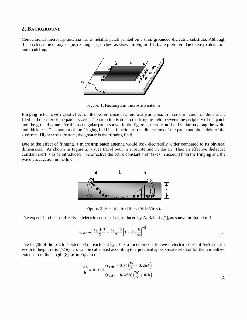
Fringing fields have a great effect on the performance of a microstrip antenna. In microstrip antennas the electric
filed in the center of the patch is zero. The radiation is due to the fringing field between the periphery of the patch
and the ground plane. For the rectangular patch shown in the figure 2, there is no field variation along the width
and thickness. The amount of the fringing field is a function of the dimensions of the patch and the height of the
substrate. Higher the substrate, the greater is the fringing field.
Due to the effect of fringing, a microstrip patch antenna would look electrically wider compared to its physical
dimensions. As shown in Figure 2, waves travel both in substrate and in the air. Thus an effective dielectric
constant εreff is to be introduced. The effective dielectric constant εreff takes in account both the fringing and the
wave propagation in the line.
Figure. 2. Electric field lines (Side View).
The expression for the effective dielectric constant is introduced by A. Balanis [7], as shown in Equation 1.
(1)
The length of the patch is extended on each end by ΔL is a function of effective dielectric constant and the
width to height ratio (W/h). ΔL can be calculated according to a practical approximate relation for the normalized
extension of the length [8], as in Equation 2.
(2)
L
W
ɛr
y
x
L εr
R
d
d
d
s
s
d
z
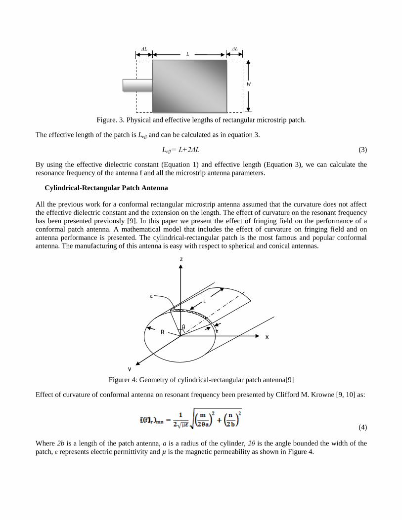
Figure. 3. Physical and effective lengths of rectangular microstrip patch.
The effective length of the patch is Leff and can be calculated as in equation 3.
Leff = L+2ΔL (3)
By using the effective dielectric constant (Equation 1) and effective length (Equation 3), we can calculate the
resonance frequency of the antenna f and all the microstrip antenna parameters.
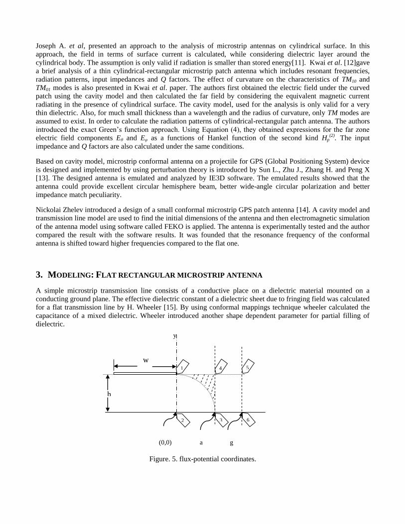
Cylindrical-Rectangular Patch Antenna
All the previous work for a conformal rectangular microstrip antenna assumed that the curvature does not affect
the effective dielectric constant and the extension on the length. The effect of curvature on the resonant frequency
has been presented previously [9]. In this paper we present the effect of fringing field on the performance of a
conformal patch antenna. A mathematical model that includes the effect of curvature on fringing field and on
antenna performance is presented. The cylindrical-rectangular patch is the most famous and popular conformal
antenna. The manufacturing of this antenna is easy with respect to spherical and conical antennas.
Figurer 4: Geometry of cylindrical-rectangular patch antenna[9]
Effect of curvature of conformal antenna on resonant frequency been presented by Clifford M. Krowne [9, 10] as:
(4)
Where 2b is a length of the patch antenna, a is a radius of the cylinder, 2θ is the angle bounded the width of the
patch, ε represents electric permittivity and µ is the magnetic permeability as shown in Figure 4.
W
ΔL L
ΔL
Joseph A. et al, presented an approach to the analysis of microstrip antennas on cylindrical surface. In this
approach, the field in terms of surface current is calculated, while considering dielectric layer around the
cylindrical body. The assumption is only valid if radiation is smaller than stored energy[11]. Kwai et al. [12]gave
a brief analysis of a thin cylindrical-rectangular microstrip patch antenna which includes resonant frequencies,
radiation patterns, input impedances and Q factors. The effect of curvature on the characteristics of TM10 and
TM01 modes is also presented in Kwai et al. paper. The authors first obtained the electric field under the curved
patch using the cavity model and then calculated the far field by considering the equivalent magnetic current
radiating in the presence of cylindrical surface. The cavity model, used for the analysis is only valid for a very
thin dielectric. Also, for much small thickness than a wavelength and the radius of curvature, only TM modes are
assumed to exist. In order to calculate the radiation patterns of cylindrical-rectangular patch antenna. The authors
introduced the exact Green’s function approach. Using Equation (4), they obtained expressions for the far zone
electric field components Eθ and Eφ as a functions of Hankel function of the second kind Hp(2)
. The input
impedance and Q factors are also calculated under the same conditions.
Based on cavity model, microstrip conformal antenna on a projectile for GPS (Global Positioning System) device
is designed and implemented by using perturbation theory is introduced by Sun L., Zhu J., Zhang H. and Peng X
[13]. The designed antenna is emulated and analyzed by IE3D software. The emulated results showed that the
antenna could provide excellent circular hemisphere beam, better wide-angle circular polarization and better
impedance match peculiarity.
Nickolai Zhelev introduced a design of a small conformal microstrip GPS patch antenna [14]. A cavity model and
transmission line model are used to find the initial dimensions of the antenna and then electromagnetic simulation
of the antenna model using software called FEKO is applied. The antenna is experimentally tested and the author
compared the result with the software results. It was founded that the resonance frequency of the conformal
antenna is shifted toward higher frequencies compared to the flat one.
3. MODELING: FLAT RECTANGULAR MICROSTRIP ANTENNA
A simple microstrip transmission line consists of a conductive place on a dielectric material mounted on a
conducting ground plane. The effective dielectric constant of a dielectric sheet due to fringing field was calculated
for a flat transmission line by H. Wheeler [15]. By using conformal mappings technique wheeler calculated the
capacitance of a mixed dielectric. Wheeler introduced another shape dependent parameter for partial filling of
dielectric.
Figure. 5. flux-potential coordinates.
w
y
(0,0)
a
h
5
6
1
2
4
3
g
As explained by Wheeler the rectangle bounded by points 3, 4, 5 and 6 is filled with dielectric. But the other
rectangle except the shaded area is empty of dielectric. The entire area is expressed as h×s˴, in which s
˴ is its
effective width on the x˴ axis. The other part of the area is h×s
˴˴ which represents the “parallel” component of the
dielectric with the air. So, the remaining area h×( s˴ + s
˴˴) represents the series components with the free space
region outside of the dielectric. This analysis gives a close approximation of the effect of the shaded area of
dielectric, which is a small part of the total effect of the dielectric. So, the effective width s of the shaded area is
between boundary s˴ and s
˴˴, and by using the concepts of parallel capacitance per unit length, we can calculate the
effective value of the width s˴˴ as follow.
(5)
Where, is the capacitance of the series component, is the capacitance of the parallel component. By using
the concepts of parallel plate capacitors, we can get the following:
(6)
So, the resultant effective width is found to be
(7)
From the concept of filling fraction; it is defined as the ratio of dielectric area over total area in the rectangle of
field mapping. So, the effective filling fraction is found by:
(8)
The relation between the effective filling fraction q and the effective dielectric constant can be stated from the
concept of parallel capacitors as a ratio between, the air capacitor subtracted from total effective capacitor and the
air capacitor subtracted from the total dielectric capacitor. So, the filling factor can be written as:
(9)
And, hence, the effective dielectric constant can be represented by the next Equation using Equation (7):
(10)
Where a′/g
′ represents a free-space flux ratio.
4. Modeling: Conformal rectangular microstrip antenna
In this section, we will present model for evaluating the fringing field effects in conformal antenna. The model is
based on approximation model developed by Wheeler [15]. A rectangular microstrip conformed on a cylindrical
body as shown in Figure 4. The height of the dielectric material is h, the length is L and the radius of curvature is
R. In case of conformal microstrip the fringing field will be affected with the curvature, and due to that the

resonance frequency also will be a function of the curvature. Figure 6 shows the effect of curvature on the
fringing field.
Figure 6: The effect of curvature on the fringing field.
An extra shaded area, the extended fringing field, is due to the curvature of the substrate. In addition to wave
traveling in substrate and air, effective dielectric constant also depends upon dielectric material due to conformal
structure. In such conformal structures, waves take a longer distance in the dielectric material than in flat
microstrip. The extra area due to curvature can be modeled by a series capacitor. This model is an extension to
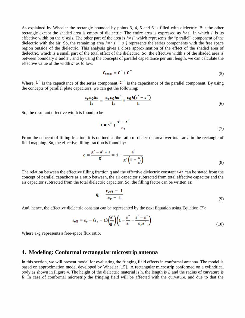
model presented by wheeler [15]. Figure 7 show two parallel capacitors Cair and Cdielectric. The capacitors are due
to the fringing field passing through the air and then through the dielectric material. An additional parallel
capacitor Cdielectric is due to the electric field passing in the dielectric material directly without passing the air. The
extra capacitor is a series capacitor with the equivalent capacitor of the parallel capacitors.
The effective capacitor is calculated as in Equation 11:
(11)
So, the effective width for the equivalent capacitor seff is given by Equation (13) as a function of area of the
shaded area shown in Figure 6 and the thickness of that area.
The effective filling factor is given by [10]:
(12)
By using Equation (9), we get a general expression for the effective dielectric constant for a curvature surface as
in Equation (14):
Figure 7. Equivalent capacitors for the fringing field
After some calculations, the effective width is given by Equation 13:
(13)
(14)
A and x can be easily calculated using simple concepts of geometry. Hence the effective length of the antenna can
be calculated using Equation (3).
5. Results
For a flat microstrip printed antenna operates at a resonance frequency around 2.2 GHz, we get the following
dimensions, using a flat antenna equations, for antenna patch: the original length is 41.5 cm, the width is 50 cm.
For the calculated dimensions, the dominate modes at this frequency are TM01 and TM10 when h<<W.
Three different substrate materials RT/duroid-5880 PTFE, K-6098 Teflon/Glass, and Epsilam-10 ceramic-filled
Teflon are used for verifying the new model discussed in section 4. The dielectric constants for the used materials
are 2.2, 2.5 and 10 respectively with a tangent loss 0.0015, 0.002 and 0.0004 respectively.
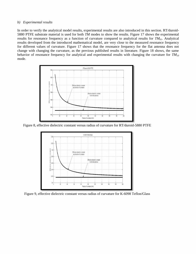
a) Analytical results
The relation between the effective dielectric constant and radius of curvature for the three substrates are shown in
Figures 8, 9, 10. We can see that effective dielectric constant decreases as the radius of curvature increases. For
TM01, the resonance frequencies versus radius of curvature for the three substrates are shown in Figures 11, 12,
and 13. The resonance frequencies for flat antennas are 2.148 GHz, 1.929 GHz, and 0.961 GHz respectively.For
TM10, the resonance frequencies versus radius of curvature for the three substrates are shown in Figures 14, 15,
and 16. The resonance frequencies for the flat antennas are 2.588 GHz, 2.324 GHz, and 1.158 GHz respectively.
Cdielectric Cair, Cdielectric
Cextra
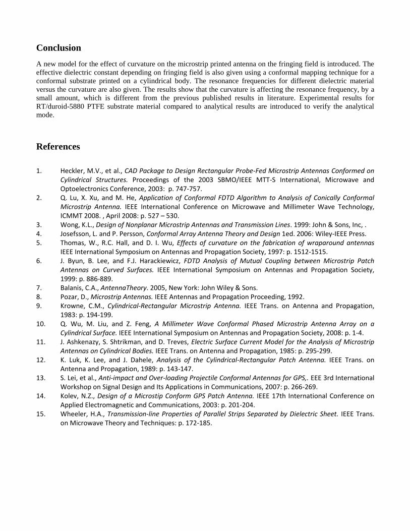
b) Experimental results
In order to verify the analytical model results, experimental results are also introduced in this section. RT/duroid-
5880 PTFE substrate material is used for both TM modes to show the results. Figure 17 shows the experimental
results for resonance frequency as a function of curvature compared to analytical results for TM01. Analytical
results developed from the introduced mathematical model, are very close to the measured resonance frequency
for different values of curvature. Figure 17 shows that the resonance frequency for the flat antenna does not
change with changing the curvature, as the previous published results in literature. Figure 18 shows, the same
behavior of resonance frequency for analytical and experimental results with changing the curvature for TM10
mode.
Figure 8, effective dielectric constant versus radius of curvature for RT/duroid-5880 PTFE
Figure 9, effective dielectric constant versus radius of curvature for K-6098 Teflon/Glass
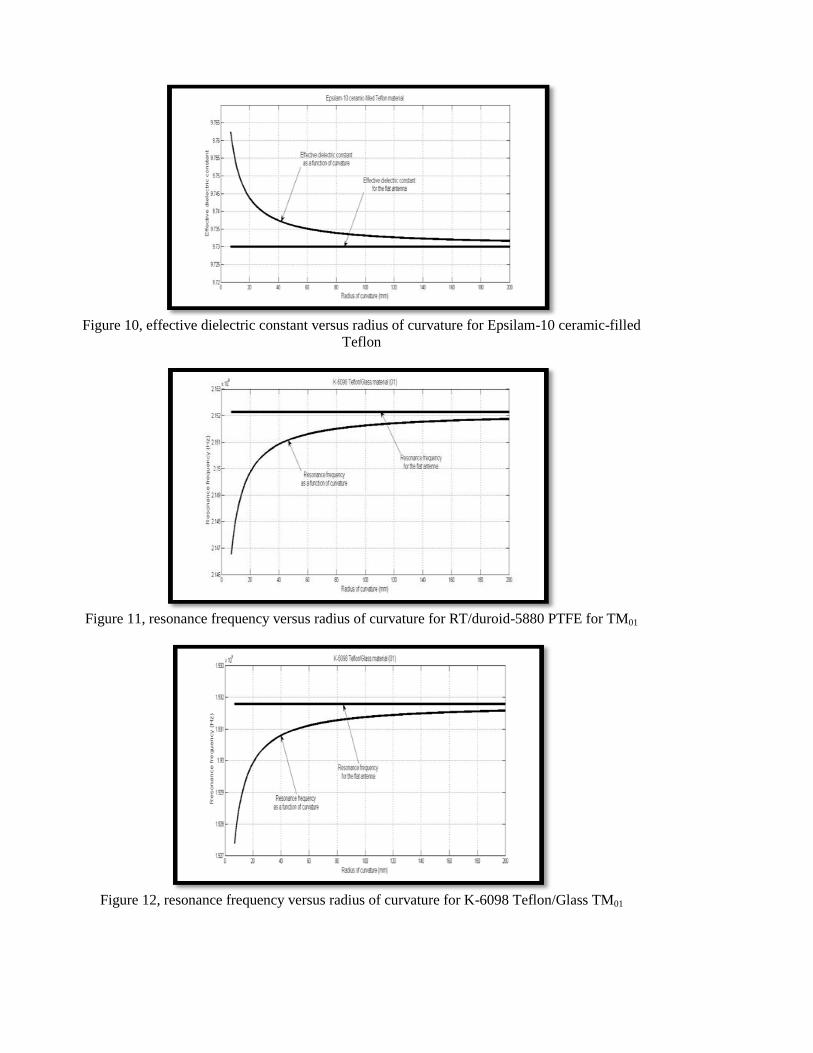
Figure 10, effective dielectric constant versus radius of curvature for Epsilam-10 ceramic-filled
Teflon
Figure 11, resonance frequency versus radius of curvature for RT/duroid-5880 PTFE for TM01
Figure 12, resonance frequency versus radius of curvature for K-6098 Teflon/Glass TM01

Figure 13, resonance frequency versus radius of curvature for Epsilam-10 ceramic-filled Teflon
TM01
Figure 14, resonance frequency versus radius of curvature for RT/duroid-5880 PTFE for TM10
Figure 15, resonance frequency versus radius of curvature for K-6098 Teflon/Glass TM10
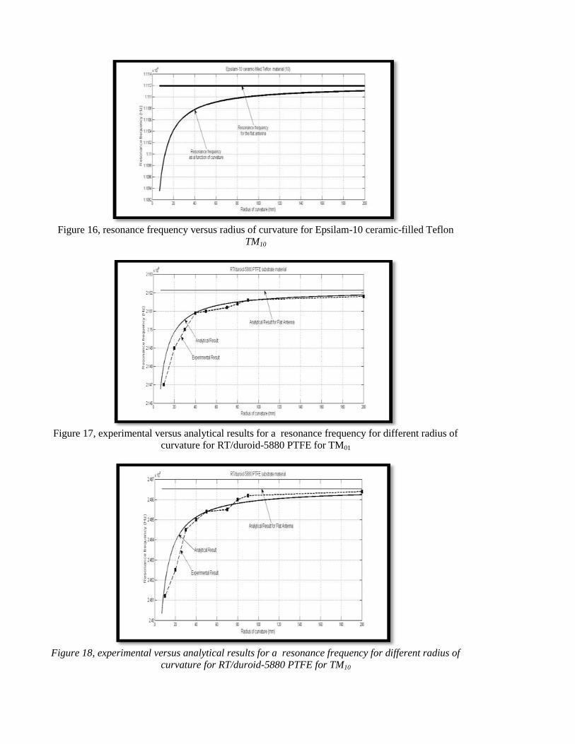
Figure 16, resonance frequency versus radius of curvature for Epsilam-10 ceramic-filled Teflon
TM10
Figure 17, experimental versus analytical results for a resonance frequency for different radius of
curvature for RT/duroid-5880 PTFE for TM01
Figure 18, experimental versus analytical results for a resonance frequency for different radius of
curvature for RT/duroid-5880 PTFE for TM10
Conclusion
A new model for the effect of curvature on the microstrip printed antenna on the fringing field is introduced. The
effective dielectric constant depending on fringing field is also given using a conformal mapping technique for a
conformal substrate printed on a cylindrical body. The resonance frequencies for different dielectric material
versus the curvature are also given. The results show that the curvature is affecting the resonance frequency, by a
small amount, which is different from the previous published results in literature. Experimental results for
RT/duroid-5880 PTFE substrate material compared to analytical results are introduced to verify the analytical
mode.
References
1. Heckler, M.V., et al., CAD Package to Design Rectangular Probe-Fed Microstrip Antennas Conformed on Cylindrical Structures. Proceedings of the 2003 SBMO/IEEE MTT-S International, Microwave and Optoelectronics Conference, 2003: p. 747-757.
2. Q. Lu, X. Xu, and M. He, Application of Conformal FDTD Algorithm to Analysis of Conically Conformal Microstrip Antenna. IEEE International Conference on Microwave and Millimeter Wave Technology, ICMMT 2008. , April 2008: p. 527 – 530.
3. Wong, K.L., Design of Nonplanar Microstrip Antennas and Transmission Lines. 1999: John & Sons, Inc, . 4. Josefsson, L. and P. Persson, Conformal Array Antenna Theory and Design 1ed. 2006: Wiley-IEEE Press. 5. Thomas, W., R.C. Hall, and D. I. Wu, Effects of curvature on the fabrication of wraparound antennas
IEEE International Symposium on Antennas and Propagation Society, 1997: p. 1512-1515. 6. J. Byun, B. Lee, and F.J. Harackiewicz, FDTD Analysis of Mutual Coupling between Microstrip Patch
Antennas on Curved Surfaces. IEEE International Symposium on Antennas and Propagation Society, 1999: p. 886-889.
7. Balanis, C.A., AntennaTheory. 2005, New York: John Wiley & Sons. 8. Pozar, D., Microstrip Antennas. IEEE Antennas and Propagation Proceeding, 1992. 9. Krowne, C.M., Cylindrical-Rectangular Microstrip Antenna. IEEE Trans. on Antenna and Propagation,
1983: p. 194-199. 10. Q. Wu, M. Liu, and Z. Feng, A Millimeter Wave Conformal Phased Microstrip Antenna Array on a
Cylindrical Surface. IEEE International Symposium on Antennas and Propagation Society, 2008: p. 1-4. 11. J. Ashkenazy, S. Shtrikman, and D. Treves, Electric Surface Current Model for the Analysis of Microstrip
Antennas on Cylindrical Bodies. IEEE Trans. on Antenna and Propagation, 1985: p. 295-299. 12. K. Luk, K. Lee, and J. Dahele, Analysis of the Cylindrical-Rectangular Patch Antenna. IEEE Trans. on
Antenna and Propagation, 1989: p. 143-147. 13. S. Lei, et al., Anti-impact and Over-loading Projectile Conformal Antennas for GPS,. EEE 3rd International
Workshop on Signal Design and Its Applications in Communications, 2007: p. 266-269. 14. Kolev, N.Z., Design of a Microstip Conform GPS Patch Antenna. IEEE 17th International Conference on
Applied Electromagnetic and Communications, 2003: p. 201-204. 15. Wheeler, H.A., Transmission-line Properties of Parallel Strips Separated by Dielectric Sheet. IEEE Trans.
on Microwave Theory and Techniques: p. 172-185.