The Fourth Fuel & Combustion Conference of IRAN -...
10
The Fourth Fuel & Combustion Conference of IRAN Kashan - IRAN Feb. 2012 University of Kashan FCCI2012-3032 1 NUMERICAL SIMULATION OF POROUS MEDIUM INTERNAL COMBUSTION ENGINE Arash Mohammadi *,§ , Ali Jazayeri ** Masoud Ziabasharhagh *** * PhD student , K.N.Toosi University of Technology ** Associated Professor , K.N.Toosi University of Technology *** Associated Professor , K.N.Toosi University of Technology ( § [email protected]) ABSTRACT: Porous media (PM) has interesting advantages compared with free flame combustion due to the higher burning rates, the increased power range, the extension of the lean flammability limits, and the low emissions of pollutants. Future internal combustion (IC) engines should have had minimum emissions level, under possible lowest fuel consumption permitted at all operational conditions. This may be achieved by realization of homogeneous combustion process in engine. In this paper, possibility of using PM in direct injection IC engine, with cylindrical geometry for PM to have homogeneous combustion, is examined. A three-dimensional numerical model for the regenerative engine is presented in this study based on a modified version of the KIVA-3V code that is very popular for engine simulation. Methane as a fuel is injected directly inside hot PM that is assumed mounted in cubic head. Very lean mixture is formed and volumetric combustion occurs in PM. Mixture formation, pressure, temperature distribution in both phases of PM and in-cylinder fluid with the production of pollutants CO and NO, in the closed part of the cycle is studied. Keywords: Direct injection engine- Methane- Porous media-emission INTRODUCTION The most important issue of internal combustion engines that currently exists, is non- homogeneous mixture formation in the combustion chamber, which causes heterogeneous heat release and high temperature gradient in combustion chamber and thus production of pollutants such as NO x , unburned hydrocarbons, carbon monoxide, soot and suspended particles. To avoid the temperature gradient in IC engines, homogeneous charge compression ignition (HCCI) engines, as an option, have been proposed. Control problems with start of ignition time under variable engine operational conditions and heat release rate, in this type of engines exist. In such engines, lean mixture with high amount of exhaust gas recycled (EGR), should be used that increases amount of carbon monoxide and soot particles, also with increasing the load of engine, NO x formation and fuel consumption increases. Other important problem is that main oxidation of fuel should be occurred in the expansion process to reduce the maximum temperature and hence, low compression ratio should be used for these engines, while in reality, the compression ratio must be high enough that temperature at the end of compression process, lead to self-ignition of mixture with reasonable delay time. So, this type of engines is suitable for low and medium loads, thereby, it is better in high loads, they work in mode of compression ignition [1-3]. In direct injection engines, generally lack of
-
Upload
truongduong -
Category
Documents
-
view
223 -
download
1
Transcript of The Fourth Fuel & Combustion Conference of IRAN -...
The Fourth Fuel & Combustion Conference of IRAN Kashan - IRAN Feb. 2012 University of Kashan FCCI2012-3032
1
NUMERICAL SIMULATION OF POROUS MEDIUM INTERNAL COMBUSTION ENGINE
Arash Mohammadi*,§, Ali Jazayeri** Masoud Ziabasharhagh***
* PhD student , K.N.Toosi University of Technology ** Associated Professor , K.N.Toosi University of Technology
*** Associated Professor , K.N.Toosi University of Technology (§[email protected])
ABSTRACT: Porous media (PM) has interesting advantages compared with free flame combustion due to the higher burning rates, the increased power range, the extension of the lean flammability limits, and the low emissions of pollutants. Future internal combustion (IC) engines should have had minimum emissions level, under possible lowest fuel consumption permitted at all operational conditions. This may be achieved by realization of homogeneous combustion process in engine. In this paper, possibility of using PM in direct injection IC engine, with cylindrical geometry for PM to have homogeneous combustion, is examined. A three-dimensional numerical model for the regenerative engine is presented in this study based on a modified version of the KIVA-3V code that is very popular for engine simulation. Methane as a fuel is injected directly inside hot PM that is assumed mounted in cubic head. Very lean mixture is formed and volumetric combustion occurs in PM. Mixture formation, pressure, temperature distribution in both phases of PM and in-cylinder fluid with the production of pollutants CO and NO, in the closed part of the cycle is studied. Keywords: Direct injection engine- Methane- Porous media-emission
INTRODUCTION
The most important issue of internal combustion engines that currently exists, is non-homogeneous mixture formation in the combustion chamber, which causes heterogeneous heat release and high temperature gradient in combustion chamber and thus production of pollutants such as NOx, unburned hydrocarbons, carbon monoxide, soot and suspended particles. To avoid the temperature gradient in IC engines, homogeneous charge compression ignition (HCCI) engines, as an option, have been proposed. Control problems with start of ignition time under variable engine operational conditions and heat release rate, in this type of engines exist. In such engines, lean mixture with high amount of exhaust gas recycled (EGR), should be used that increases amount of carbon monoxide and soot particles, also with increasing the load of engine, NOx formation and fuel consumption increases. Other important problem is that main oxidation of fuel should be occurred in the expansion process to reduce the maximum temperature and hence, low compression ratio should be used for these engines, while in reality, the compression ratio must be high enough that temperature at the end of compression process, lead to self-ignition of mixture with reasonable delay time. So, this type of engines is suitable for low and medium loads, thereby, it is better in high loads, they work in mode of compression ignition [1-3]. In direct injection engines, generally lack of

The Fourth Fuel & Combustion Conference of IRAN Kashan - IRAN Feb. 2012 University of Kashan FCCI2012-3032
2
homogeneous mixture formation and combustion, is unsolved problem yet. On the other hand, various methods are used for reducing pollutants in IC engines, such as high pressure fuel injection, variable valve timing, EGR, or adaptive and fuzzy control methods for setting the air fuel ratio and mixture formation but actually combination of these methods cannot solve air pollution problem under all conditions. Thus, this is a question, what is the method of homogeneous combustion in IC engines under all operational conditions (load and speed)? This target may be possible with volumetric combustion and prevent from formation of three-dimensional flame front that lead to temperature gradient in the combustion chamber. PM as an option is used to achieve homogeneous mixing and combustion in all conditions to reduce combustion temperature and formation of pollutions [3, 4]. Flame stability in PM with lean and rich mixtures, significant reduction in pollutants and increasing combustion efficiency, was proven [5, 6]. The first idea to use PM in the IC engines was proposed by Weclas and Durst in 2001. They investigated the performance of a PM in single-cylinder, air-cooled diesel engine, without using of catalyst. They mounted a Silicon Carbide (SIC) PM in the cylinder head between the intake and exhaust valves and removed bowl of the piston. Their results showed increasing in engine efficiency, reducing the emissions and noise in comparison with the original engine. The mean cylinder temperature, about 2200 K in normal operational condition without PM, decreases to 1500 K with PM and also, it did not change significantly during combustion process [7, 8]. In 2002, Park and Kaviany simulated the effect of a SIC PM as a regenerative, which was moving near piston in the cylinder of diesel engine. They used thermodynamic two-zone model, single-step reaction for methane/air combustion, Lagrangian model for determination of motion droplets in fuel injection and showed that the maximum cylinder pressure during combustion increases and hence more work is done during a cycle, also engine efficiency increases, but due to high temperature of PM that its temperature is higher that adiabatic flame temperature of methane/air, the production of NOx is higher than normal operation, while the amount of soot decreases [9]. In 2003, Macek and Plasek simulated IC engine with a PM for homogenization of mixture and combustion stability [10]. In 2006, Hwan, Ou and Chein mounted PM on the piston bowl of single-cylinder diesel engine and observed that power increases and noise decreases because of reduction in maximum value of pressure, also amount of NOx decreases significantly while, unburned hydrocarbons and soot increase [11]. In 2007 Weclas and Faltermeier investigated the effect of liquid-fuel injection in a PM, as a matrix set of cylinders, with different diameters that were mounted on a flat plate and changed the arrangement of cylinders to find optimum geometry for PM that could produce the best mixture formation [12]. In 2008, MaoZhao and ZhiGuo studied homogeneous combustion in a PM compression ignition. They used KIVA-3V code for their simulation. Methane was injected inside hot PM and combustion occurred. They studied effect of initial temperature of PM and fuel injection time on the mean cylinder temperature and pressure. Their computational results showed that the initial temperature of PM is the key factor to start of combustion [13]. In 2008, MaoZhao and ZhiGuo simulated the injection of liquid fuel in axisymmetry PM engine with KIVA-3V code to investigate the effect of injection pressure and spray cone angle on hot PM in order to study the penetration of droplets in PM [15]. In 2008, Liu, Wu and Maozaho studied combustion and expansion processes. They used the two-zone model, effect of heat transfer from the cylinder wall, the mass exchange between zones and heat transfer from PM was considered to investigate the effect of inlet temperature and pressure and the compression ratio and excess air on the performance of engine and showed that the minimum value for compression ratio and initial temperature of PM on the start of combustion [16]. In 2009, Liu, Wu and Maozaho
The Fourth Fuel & Combustion Conference of IRAN Kashan - IRAN Feb. 2012 University of Kashan FCCI2012-3032
3
investigated working process of PM IC engine with ideal thermodynamic model and evaluated the influences of the expansion ratio, initial temperature on the net work that is done and efficiency of the engine[16].
GOVERNING EQUATIONS
For simulation of PM engine, some assumptions were used for modeling of thePM, include: (1) There is thermal non-equilibrium between gas and solid phases. (2) Solid is homogeneous, isotropic, variable property with temperature and has no catalyst effect. (3) Radiation heat transfer from the solid phase is considered only and the gas phase is transparent. Regard to the above assumptions, governing equations are: Continuity equation: (1)
ρg is mixture density, ε is porosity of porous media and is velocity vector. Gas phase momentum equation:
(2)
(3)
Gas phase energy equation:
, Nuv = 2 + 1.1 Re0.6 Pr0.33 (7)
cp is specific heat of mixture, Tg is gas temperature, Yi is mass fraction species i, ώi is rate of reaction i, Vi is diffusion velocity i, hi is enthalpy of species i, Wi is molecular weight of species i, kg is thermal conductivity of the fluid, D||
d is thermal dispersion coefficient along the length of the porous medium, hv is volumetric heat transfer coefficient. Correlation (7) was estimated from experimental data by Wakao and Kaguei for heat transfer between packed beds and fluid [17]. Solid phase energy equation:
(8)
Ts is solid temperature, ρs is solid density, cs is specific heat of solid medium, ks is thermal conductivity of solid, qr is the radiation heat transfer in solid. Chemical species continuity equation:
(9)
(10)
Xi is molar fraction of species i, Pe is Peclet number, Dim is diffusion coefficient of species i is mixture. Turbulence model: The transport equation for κ turbulent kinetic energy:
The Fourth Fuel & Combustion Conference of IRAN Kashan - IRAN Feb. 2012 University of Kashan FCCI2012-3032
4
(12)
with a similar one for the dissipation rate, ε: (13)
The quantities , , , and are constant whose values are determined from experiments and some theoretical considerations. is viscous stress tensor [20, 21]. Equation of state:
(14)
R is universal constant of gases, average molecular weight of mixture, P is pressure inside the combustion chamber and the porous medium. Combustion model: Chemical mechanism for oxidation of methane fuel is considered. ώi chemical production rate: (15)
and are stoichiometric coefficients. Combustion process includes ten equations and twelve species. In order to consider effects of turbulence on combustion, Eddy-Dissipation model [18] has been used.
Radiation model: Due to high temperature of combustion zone, and high temperature of solid, radiation heat transfer is very important. Gas phase radiation in comparison with solid phase, that has a high absorption coefficient, is regardless. Several relations for modeling of radiation heat transfer and obtain the radiation intensity were presented. The heat source term , due to radiation in solid phase that appears in Eq .8, is calculated from Rosseland [19] method.
(16)
σ Boltzmann constant and β is extinction coefficient.
MESH PREPARATION
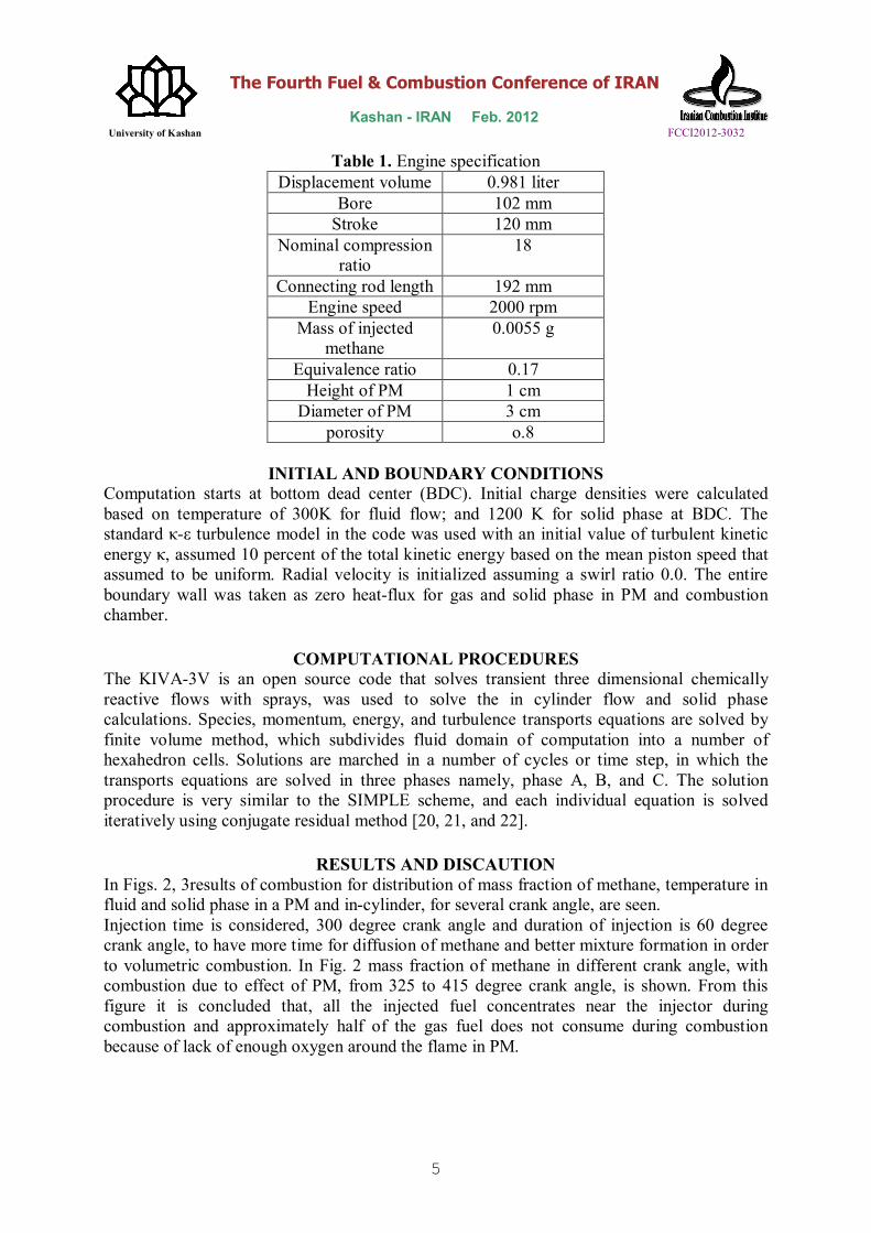
The engine specifications have been presented in Table. 1. Prior to CFD simulation, computational mesh was generated for the engine. The geometry of a mesh is composed of several numbers of logical blocks that are patched together in a seamless fashion. Patching allows geometry to be created, block by block. Fig.1 shows the grid configuration of the engine at top dead center (TDC).
Figure 1. Computational mesh for the CFD calculation at TDC
PM
Cylinder
Injector
The Fourth Fuel & Combustion Conference of IRAN Kashan - IRAN Feb. 2012 University of Kashan FCCI2012-3032
5
Table 1. Engine specification Displacement volume 0.981 liter
Bore 102 mm Stroke 120 mm
Nominal compression ratio
18
Connecting rod length 192 mm Engine speed 2000 rpm
Mass of injected methane
0.0055 g
Equivalence ratio 0.17 Height of PM 1 cm
Diameter of PM 3 cm porosity o.8
INITIAL AND BOUNDARY CONDITIONS
Computation starts at bottom dead center (BDC). Initial charge densities were calculated based on temperature of 300K for fluid flow; and 1200 K for solid phase at BDC. The standard κ-ε turbulence model in the code was used with an initial value of turbulent kinetic energy κ, assumed 10 percent of the total kinetic energy based on the mean piston speed that assumed to be uniform. Radial velocity is initialized assuming a swirl ratio 0.0. The entire boundary wall was taken as zero heat-flux for gas and solid phase in PM and combustion chamber.
COMPUTATIONAL PROCEDURES The KIVA-3V is an open source code that solves transient three dimensional chemically reactive flows with sprays, was used to solve the in cylinder flow and solid phase calculations. Species, momentum, energy, and turbulence transports equations are solved by finite volume method, which subdivides fluid domain of computation into a number of hexahedron cells. Solutions are marched in a number of cycles or time step, in which the transports equations are solved in three phases namely, phase A, B, and C. The solution procedure is very similar to the SIMPLE scheme, and each individual equation is solved iteratively using conjugate residual method [20, 21, and 22].
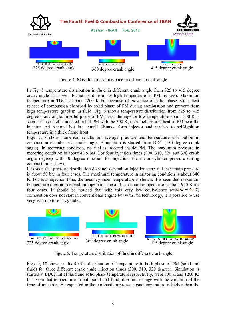
RESULTS AND DISCAUTION In Figs. 2, 3results of combustion for distribution of mass fraction of methane, temperature in fluid and solid phase in a PM and in-cylinder, for several crank angle, are seen. Injection time is considered, 300 degree crank angle and duration of injection is 60 degree crank angle, to have more time for diffusion of methane and better mixture formation in order to volumetric combustion. In Fig. 2 mass fraction of methane in different crank angle, with combustion due to effect of PM, from 325 to 415 degree crank angle, is shown. From this figure it is concluded that, all the injected fuel concentrates near the injector during combustion and approximately half of the gas fuel does not consume during combustion because of lack of enough oxygen around the flame in PM.
The Fourth Fuel & Combustion Conference of IRAN Kashan - IRAN Feb. 2012 University of Kashan FCCI2012-3032
6
325 degree crank angle
360 degree crank angle
415 degree crank angle
Figure 4. Mass fraction of methane in different crank angle
In Fig .5 temperature distribution in fluid in different crank angle from 325 to 415 degree crank angle is shown. Flame front from its high temperature in PM, is seen. Maximum temperature in TDC is about 2200 K but because of existence of solid phase, some heat release of combustion absorbed by solid phase of PM during combustion and prevent from high temperature gradient in fluid. Fig. 6 shows temperature distribution from 325 to 415 degree crank angle, in solid phase of PM. Near the injector low temperature about, 300 K is seen because fuel is injected in hot PM with the 300 K, then fuel absorbs heat of PM near the injector and become hot in a small distance form injector and reaches to self-ignition temperature in a thick flame front. Figs. 7, 8 show numerical results for average pressure and temperature distribution in combustion chamber via crank angle. Simulation is started from BDC (180 degree crank angle). In motoring condition, no fuel is injected inside PM. The maximum pressure in motoring condition is about 43.5 bar. For four injection times (300, 310, 320 and 330 crank angle degree) with 10 degree duration for injection, the mean cylinder pressure during combustion is shown. It is seen that pressure distribution does not depend on injection time and maximum pressure is about 50 bar in four cases. The maximum temperature in motoring condition is about 840 K. For four injection time, the mean cylinder temperature is shown. It is seen that maximum temperature does not depend on injection time and maximum temperature is about 950 K for four cases. It should be noticed that with this very low equivalence ratio ) combustion does not start in conventional engine but with PM technology, it is possible to use very lean mixture in cylinder.
325 degree crank angle
360 degree crank angle
415 degree crank angle
Figure 5. Temperature distribution of fluid in different crank angle
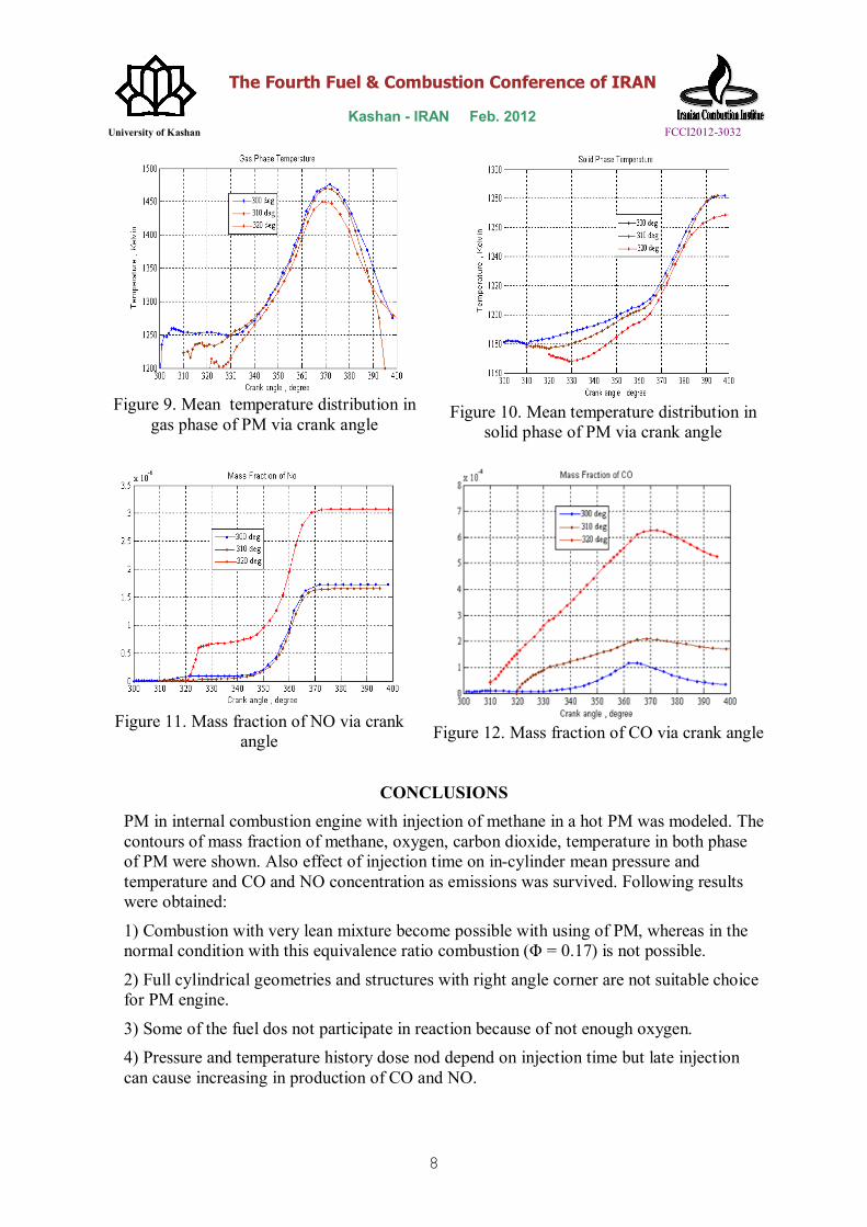
Figs. 9, 10 show results for the distribution of temperature in both phase of PM (solid and fluid) for three different crank angle injection times (300, 310, 320 degree). Simulation is started at BDC, initial fluid and solid phase temperature respectively, were 300 K and 1200 K. It is seen that temperature in both solid and fluid, does not change with the variation of the time of injection. As expected in the combustion process, gas temperature is higher than the

The Fourth Fuel & Combustion Conference of IRAN Kashan - IRAN Feb. 2012 University of Kashan FCCI2012-3032
7
solid temperature and heat is accumulates in solid phase due to high heat capacity of it. It showed that, however the mass of the fuel is very low value but combustion is started in PM.
325 degree crank angle
360 degree crank angle
415 degree crank angle
Figure 6. Temperature distribution in solid phase of PM in different crank angle
Figure 7. Mean pressure distribution in
cylinder via crank angle
Figure 8. Fluid mean temperature
distribution in (both in-cylinder and PM) cylinder via crank angle
Figs. 11, 12 show mass fraction of CO and NO via crank angle. Carbon monoxide is produced during combustion and with start of combustion suddenly increases and the CO concentration reaches its highest value and gradually decreases with completeness of combustion and is converted to CO2 and its value is reduced, but combustion is done in little duration and heat is released in little time that causes to high temperature and CO have not enough time to convert to CO2. It is concluded that injection time later than 310 degree crank angle, production of CO become very high and late injection should be avoided. As can be seen NO value at the beginning of the simulation is negligible due to low in-cylinder temperature. It seen that approximately after 60 degree crank angle, fluid phase of PM temperature reaches to highest value about 1780 K and decreasing in temperature after this time occurs and hence, no more NO if produced. But due to the fact that the temperature is considerably lower than normal condition of in-cylinder temperature (below 1800K), NO value is lower relative to normal operating condition.
The Fourth Fuel & Combustion Conference of IRAN Kashan - IRAN Feb. 2012 University of Kashan FCCI2012-3032
8
Figure 9. Mean temperature distribution in
gas phase of PM via crank angle
Figure 10. Mean temperature distribution in solid phase of PM via crank angle
Figure 11. Mass fraction of NO via crank
angle
Figure 12. Mass fraction of CO via crank angle
CONCLUSIONS
PM in internal combustion engine with injection of methane in a hot PM was modeled. The contours of mass fraction of methane, oxygen, carbon dioxide, temperature in both phase of PM were shown. Also effect of injection time on in-cylinder mean pressure and temperature and CO and NO concentration as emissions was survived. Following results were obtained:
1) Combustion with very lean mixture become possible with using of PM, whereas in the normal condition with this equivalence ratio combustion (Φ = 0.17) is not possible.
2) Full cylindrical geometries and structures with right angle corner are not suitable choice for PM engine.
3) Some of the fuel dos not participate in reaction because of not enough oxygen. 4) Pressure and temperature history dose nod depend on injection time but late injection can cause increasing in production of CO and NO.

The Fourth Fuel & Combustion Conference of IRAN Kashan - IRAN Feb. 2012 University of Kashan FCCI2012-3032
9
5) After 400 degree crank angle some methane remains in combustion chamber that is mean some fuel is not combusted. In future publication, we will show and propose better geometry for PM than cylindrical type, and inclined injection relative to cylinder axis and also, squish region will be deleted for using of all capability PM.
6) After approximately 70 degree crank angle, solid phase of PM prevents from increasing if gas phase temperature and thereby, no more NO is produced.
NOMENCLATURE
BDC bottom dead center cp specific heat of mixture cs specific heat of solid medium D||
d thermal dispersion coefficient Dim diffusion coefficient of species i in
mixture hi enthalpy of species i hv volumetric heat transfer coefficient
of PM kg thermal conductivity of the fluid ks thermal conductivity of solid Pe Peclet number qr radiation heat transfer in solid R universal constant of gases Tg gas temperature Ts solid temperature u velocity in x direction v velocity in y direction w velocity in z dorection
average molecular weight of mixture Xi molar fraction of species i Vi diffusion velocity of species i Yi mass fraction of species i ρg mixture density ε porosity of porous medium ώi rate of reaction i ρs solid density
viscous stress tensor dynamic viscosity
9. REFRENCES [1] Stanglmaier, R. H., Roberts, C. E., [1999], Homogeneous charge compression ignition: benefits, compromises and future engine applications, SAE Paper, 1999-01-3682. [2] Weclas. M. [2001], Potential of porous medium combustion technology as applied to internal combustion engine”, MECA/AECC Meeting, Nurnberg, Germany. [3] Durst, F., Weclas, M. [2003], Strategy for intelligent internal combustion engine with homogeneous combustion in cylinder, MECA/AECC Meeting, Nurnberg, Germany.

The Fourth Fuel & Combustion Conference of IRAN Kashan - IRAN Feb. 2012 University of Kashan FCCI2012-3032
10
[4] Weclas, M. [2004], Strategy for Intelligent Internal Combustion Engine with Homogeneous Combustion in Cylinder Sonderdruck Schriftenreihe University of Applied Sciences in Nuernberg, No. 26, pp. 1–14. [5] Trim, D., Durst, F. [1996], Combustion in porous medium – advances and application, Combust Sci. and Tech., Vol 121, pp. 153-168. [6] Kamal, A. A., Mohammad, A. A. [2006], Combustion in porous media, Proc. IMeche, Vol. 220, pp. 478-509. [7] Durst, F., Weclas, M. [2001], A new type of internal combustion engine based on the porous medium technology, Proc Inst Mech Eng, Vol 215, pp. 63-81. [8] Durst, F., Weclas, M. [2001], A new Concept of I.C engine with homogeneous combustion in a porous medium, The Fifth International Symposium on Diagnostic and Modeling of Combustion in Internal Combustion Engines, Nagoya, Japan. [9] Park, C. W., Kaviany, M. [2002], Evaporating combustion affected by in cylinder reciprocating porous regenerator, ASME J. Heat Transfer, Vol 124, pp. 184-194. [10] Polasek, M., Macek, J. [2003], Homogenization of combustion in cylinder of CI engine using porous medium, SAE Paper, 2003-01-1085, 2003. [11] Le, D. C., Chein, C. J., Kwak, Y. H. [2006], Improving surface characteristic of porous media reactor in diesel engine by plasma technology, F2006C27. [12] Weclas, M., Faltermeier, R. [2007], Diesel jet impingement on small cylindrical obstacles for mixture homogenization by late injection strategy, Int. J. Engine Research, Vol 8, pp. 399-413. [13] Zhigou, Z., Mahozhao, X. [2008], Numerical study on the compression ignition of a porous medium engine, Springer, Vol. 51, No.3, pp. 277-287. [14] Zhigou, Z., Mahozhao, X. [2008], Numerical simulation about interaction between pressure swirl spray and hot porous medium, Energy Conversion & Management, Vol 49, pp. 1047-1055. [15] Hongsheng, L., Maozaho, X., Shi, C., Hong, L. [2008], Simulation of porous media engine using a two-zone combustion model, SAE Paper, 2008-01-1516. [16] Hongsheng, L., Maozaho, X., Shi, C., Hong, L. [2009], Regenerative cycle in porous medium engine, J. Energy Conversion and Management, Vol. 59, pp. 273-303. [17] Wakao, N. and Kaguei, S. [1982], Heat and Mass Transfer in Packed Beds, Gordon and Breach Science Publications, New Yourk, USA. [18] Magnussen, B. F., and. Hjertager, B. H. [1977], mathematical modelling of turbulent combustion with special emphasis on soot formation and combustion, The Sixteenth Int. Symp. on Combustion, The Combustion Institute, Pittsburgh. [19] Modest, M., F. [2003], Radiative Heat Transfer, Academic Press, California, USA. [20] Mohammadi, A. [2010], Numerical Simulation of Spark Ignition Engines, Numerical Simulations – Examples and Applications in Computational Fluid Dynamics, InTech, Austria. http://www.intechopen.com/articles/show/title/numerical-simulation-of-internal-combustion-engines. [21] Amsden., A. A., O’Rourke, P. J., and Butler, T. D. [1989], KIVA-II: A Computer Program for Chemically Reactive Flows with Sprays, Los Alamos National Laboratory Report LA-11560-MS, Los Alamos.
[22] Amsden., A. A. [1997], KIVA-3V: A Block-Structured KIVA Program for Engines with Vertical or Canted Valves, Los Alamos National Laboratory Report LA-13313-MS, Los Alamos.