The Formwork Experts. Circular formwork H20 - Doka · The Formwork Experts. User Information...
40
- 999705002 07/2014 en-GB The Formwork Experts. User Information Instructions for assembly and use (Method statement) Circular formwork H20 9705-201-01
Transcript of The Formwork Experts. Circular formwork H20 - Doka · The Formwork Experts. User Information...

-999705002 07/2014en-GB
The Formwork Experts.
User InformationInstructions for assembly and use (Method statement)
Circular formwork H20
9705-201-01

2 999705002 - 07/2014
Introduction User Information Circular formwork H20
Introduction© by Doka Industrie GmbH, A-3300 Amstetten
User Information Circular formwork H20 Introduction
3999705002 - 07/2014
Contents4 Introduction4 Elementary safety warnings8 Doka services
10 Eurocodes at Doka
1111 Product description12 System grid13 Vertical stacking15 Inter-element connections16 End closures, end shuttering17 Bending instructions18 Plumbing accessories22 Pouring platforms with single brackets24 Ladder system28 Resetting29 Determining the required widths of fitting-
timber30 Transporting, stacking and storing
34 Component overview

4 999705002 - 07/2014
Introduction User Information Circular formwork H20
IntroductionElementary safety warningsUser target groups
▪ This manual is aimed at all persons who will be work-ing with the Doka product or system that it describes. It contains information on the standard design for setting up this system, and on correct, compliant uti-lisation of the system.
▪ All persons working with the product described herein must be familiar with the contents of this man-ual and with all the safety instructions it contains.
▪ Persons who are incapable of reading and under-standing this booklet, or who can do so only with dif-ficulty, must be instructed and trained by the cus-tomer.
▪ The customer is to ensure that the information mate-rials provided by Doka (e.g. User Information book-lets, Instructions for Assembly and Use, Operating Instruction manuals, plans etc.) are available to all users, and that they have been made aware of them and have easy access to them at the usage location.
▪ In the relevant technical documentation and form-work utilisation plans, Doka shows the workplace safety precautions that are necessary in order to use the Doka products safely in the usage situations shown. In all cases, users are obliged to ensure compliance with national laws, Standards and rules throughout the entire project and to take appropriate additional or alternative workplace safety precautions where necessary.
Hazard assessment
▪ The customer is responsible for drawing up, docu-menting, implementing and continually updating a hazard assessment at every job-site. This document serves as the basis for the site-spe-cific hazard assessment, and for the instructions given to users on how to prepare and utilise the sys-tem. It does not substitute for these, however.
Remarks on this document
▪ This manual can also be used as a generic method statement or incorporated with a site-specific method statement.
▪ Many of the illustrations in this booklet show the situation during formwork assembly and are therefore not always complete from the safety point of view.Any safety accessories not shown in these illustra-tions must still be used by the customer, in accord-ance with the applicable rules and regulations.
▪ Further safety instructions, especially warnings, will be found in the individual sections of this document!
Planning
▪ Provide safe workplaces for those using the form-work (e.g. for when it is being erected/dismantled, modified or repositioned etc). It must be possible to get to and from these workplaces via safe access routes!
▪ If you are considering any deviation from the details and instructions given in this booklet, or any application which goes beyond those described in the booklet, then revised static cal-culations must be produced for checking, as well as supplementary assembly instructions.
Regulations; industrial safety
▪ All laws, Standards, industrial safety regulations and other safety rules applying to the utilisation of our products in the country and/or region in which you are operating must be observed at all times.
▪ If a person or object falls against, or into, the side-guard component and/or any of its accessories, the component affected may only continue in use after it has been inspected and passed by an expert.

User Information Circular formwork H20 Introduction
5999705002 - 07/2014
Rules applying during all phases of the assignment
▪ The customer must ensure that this product is erected and dismantled, reset and generally used for its intended purpose in accordance with the applica-ble laws, Standards and rules, under the direction and supervision of suitably skilled persons. These persons' mental and physical capacity must not in any way be impaired by alcohol, medicines or drugs.
▪ Doka products are technical working appliances which are intended for industrial/commercial use only, always in accordance with the respective Doka User Information booklets or other technical docu-mentation authored by Doka.
▪ The stability of all components and units must be ensured during all phases of the construction work!
▪ The functional/technical instructions, safety warn-ings and loading data must all be strictly observed and complied with. Failure to do so can cause acci-dents and severe (even life-threatening) damage to health, as well as very great material damage.
▪ Fire-sources are not permitted anywhere near the formwork. Heating appliances are only allowed if properly and expertly used, and set up a safe dis-tance away from the formwork.
▪ The work must take account of the weather condi-tions (e.g. risk of slippage). In extreme weather, steps must be taken in good time to safeguard the equipment, and the immediate vicinity of the equip-ment, and to protect employees.
▪ All connections must be checked regularly to ensure that they still fit properly and are functioning cor-rectly. It is very important to check all screw-type connec-tions and wedge-clamped joins whenever the con-struction operations require (particularly after excep-tional events such as storms), and to tighten them if necessary.
▪ It is strictly forbidden to weld Doka products – in par-ticular anchoring/tying components, suspension components, connector components and castings etc. – or otherwise subject them to heating. Welding causes serious change in the microstruc-ture of the materials from which these components are made. This leads to a dramatic drop in the failure load, representing a very great risk to safety.The only articles which are allowed to be welded are those for which the Doka literature expressly points out that welding is permitted.
Assembly
▪ The equipment/system must be inspected by the customer before use, to ensure that it is in suitable condition. Steps must be taken to rule out the use of any components that are damaged, deformed, or weakened due to wear, corrosion or rot.
▪ Combining our formwork systems with those of other manufacturers could be dangerous, risking damage to both health and property. If you intend to combine different systems, please contact Doka for advice first.
▪ The equipment/system must be assembled and erected in accordance with the applicable laws, Standards and rules by suitably skilled personnel of the customer's, having regard to any and all required safety inspections.
▪ It is not permitted to modify Doka products; any such modifications constitute a safety risk.
Closing the formwork
▪ Doka products and systems must be set up so that all loads acting upon them are safely transferred!
Pouring
▪ Do not exceed the permitted fresh-concrete pres-sures. Over-high pouring rates overload the form-work, cause greater deflection and risk breakage.
Stripping out the formwork
▪ Do not strip out the formwork until the concrete has reached sufficient strength and the person in charge has given the order for the formwork to be stripped out!
▪ When stripping out the formwork, never use the crane to break concrete cohesion. Use suitable tools such as timber wedges, special pry-bars or system features such as Framax stripping corners.
▪ When stripping out the formwork, do not endanger the stability of any part of the structure, or of any scaffolding, platforms or formwork that is still in place!

6 999705002 - 07/2014
Introduction User Information Circular formwork H20
Transporting, stacking and storing
▪ Observe all regulations applying to the handling of formwork and scaffolding. In addition, the Doka slinging means must be used - this is a mandatory requirement.
▪ Remove any loose parts or fix them in place so that they cannot be dislodged or fall free!
▪ All components must be stored safely, following all the special Doka instructions given in the relevant sections of this manual!
Maintenance
▪ Only original Doka components may be used as spare parts. Repairs may only be carried out by the manufacturer or authorised facilities.
Miscellaneous
We reserve the right to make alterations in the interests of technical progress.
Symbols used
The following symbols are used in this booklet:
Important noteFailure to observe this may lead to malfunc-tion or damage.
CAUTION / WARNING / DANGERFailure to observe this may lead to material damage, and to injury to health which may range up to the severe or even life-threaten-ing.
InstructionThis symbol indicates that actions need to be taken by the user.
Sight-checkIndicates that you need to do a sight-check to make sure that necessary actions have been carried out.
TipPoints out useful practical tips.
ReferenceRefers to other documents and materials.
☞

User Information Circular formwork H20 Introduction
7999705002 - 07/2014

8 999705002 - 07/2014
Introduction User Information Circular formwork H20
Doka servicesSupport in every stage of the project
Doka offers a broad spectrum of services, all with a sin-gle aim: to help you succeed on the site.Every project is unique. Nevertheless, there is one thing that all construction projects have in common – and that is a basic structure with five stages. We at Doka know our clients' varying requirements. With our consulting, planning and other services, we help you achieve effective implementation of your formwork assignment using our formwork products – in every one of these stages.
Project Development Stage Bidding Stage Project Management Planning Stage
Taking well-founded decisions thanks to professional advice and consulting
Optimising the preliminary work with Doka as an experienced part-ner
Controlled, regular forming oper-ations, for greater efficiency resulting from realistically calculated formwork concepts
Find precisely the right formwork solutions, with the aid of ▪ help with the bid invitation ▪ in-depth analysis of the initial sit-
uation ▪ objective evaluation of the plan-
ning, execution, and time-risks
Draw up potentially winning bids, by ▪ basing them on realistically calcu-
lated guideline prices ▪ making the right formwork
choices ▪ having an optimum time-calcula-
tion basis
Plan cost-effectively right from the outset, thanks to ▪ detailed offers ▪ determination of the commission-
ing quantities ▪ co-ordination of lead-times and
handover deadlines
1 2 3

User Information Circular formwork H20 Introduction
9999705002 - 07/2014
The advantages for you thanks to professional advice and consulting
▪ Cost savings and time gains When we advise and support you right from the word "go", we can make sure that the right formwork systems are chosen and then used as planned. This lets you achieve optimum utilisation of the formwork equipment, and effec-tive forming operations because your workflows will be correct.
▪ Maximised workplace safety The advice and support we can give you in how to use the equip-ment correctly, and as planned, leads to greater safety on the job.
▪ Transparency Because our services and costs are completely transparent, there is no need for improvisation dur-ing the project – and no unpleas-ant surprises at the end of it.
▪ Reduced close-out costs Our professional advice on the selection, quality and correct use of the equipment helps you avoid damage, and minimise wear-and-tear.
Concrete Construction Stage Project Close-out Stage
Optimum resource utilisation with assistance from the Doka Formwork Experts
Seeing things through to a posi-tive conclusion with professional support
Workflow optimisation, thanks to ▪ thorough utilisation planning ▪ internationally experienced pro-
ject technicians ▪ appropriate transport logistics ▪ on-site support
Doka Services are a byword for transparency and efficiency here, offering ▪ jointly handled return of rented
formwork ▪ professional dismantling ▪ efficient cleaning and recondition-
ing using special equipment
4 5

10 999705002 - 07/2014
Introduction User Information Circular formwork H20
Eurocodes at DokaIn Europe, a uniform series of Standards known as Eurocodes (EC) was developed for the construction field by the end of 2007. These are intended to provide a uniform basis, valid throughout Europe, for product specifications, tenders and mathematical verification.The EC are the world's most highly developed Stand-ards in the construction field.In the Doka Group, the EC are to be used as standard from the end of 2008. They will thus supersede the DIN norms as the "Doka standard" for product design.
The widely used "Permissible stress design" (compar-ing the actual stresses with the permissible stresses) has been superseded by a new safety concept in the EC.The EC contrast the actions (loads) with the resistance (capacity). The previous safety factor in the permissible stresses is now divided into several partial factors. The safety level remains the same!
Comparison of the safety concepts (example)
Ed Design value of effect of actions (E ... effect; d ... design) Internal forces from action Fd (VEd, NEd, MEd)
Rd Design value of the resistance (R ... resistance; d ... design) Design capacity of cross-section (VRd, NRd, MRd)
Fd Design value of an action Steel: Rd =Rk Timber: Rd = kmod ·
Rk
Fd = F · Fk M M
(F ... force)Fk Characteristic value of an action
"actual load", service load (k ... characteristic) e.g. dead weight, live load, concrete pressure, wind
Rk Characteristic value of the resistance e.g. moment resistance to yield stress
F Partial factor for actions (in terms of load; F ... force) e.g. for dead weight, live load, concrete pres-sure, wind Values from EN 12812
M Partial factor for a material property (in terms of material; M...material) e.g. for steel or timber Values from EN 12812
kmod Modification factor (only for timber – to take account of the moisture and the duration of load action) e.g. for Doka beam H20 Values as given in EN 1995-1-1 and EN 13377
Ed
Rd
Permissible stress design EC/DIN concept
Factual Fpermissible Ed Rd
A Utilisation factor
60 [kN]
60<70 [kN]
115.5 [kN]
� ~ 1.65
Fyield
Fpermissible
Factual
9801
3-10
0
A
90 [kN]
115.5 [kN]
90<105 [kN]
Rk
Rd
Ed
�M
= 1.1
�F
= 1.5
9801
3-10
2
A
The "permissible values" communicated in Doka documents (e.g.: Qpermissible = 70 kN) do not correspond to the design values (e.g.: VRd = 105 kN)!➤ Avoid any confusion between the two!➤ Our documents will continue to state the per-
missible values. Allowance has been made for the following par-tial factors: F = 1.5 M, timber = 1.3 M, steel = 1.1 kmod = 0.9In this way, all the design values needed in an EC design calculation can be ascertained from the permissible values.

User Information Circular formwork H20
11999705002 - 07/2014
Product description
Further product features: ▪ Continuous adaptation to different radii by means of
spindles. ▪ Only 2 widths of element:
- 2.40 m inside element- 2.50 m outside element
▪ Ideal height grid provided by the element heights of:- 0.70 m- 1.20 m- 2.40 m- 3.00 m- 3.60 m- 4.80 m
▪ Only one type of connector needed:- Adjustable clamp 10cm
▪ Heavy-duty, flexible form-ply:- Dokaplex 21mm
▪ Smooth, constant curvature ensured by uniform form-ply support.
▪ Extra-rigid connection between connecting profile and form-ply ensures perfect curvature in the edge zone of the elements as well.
▪ Low form-tie ratio:- only 1 form-tie per 1.5 m2 area to be formed
System overviewCircular formwork H20 – the practical circular formwork for curved wallsDoka circular formwork H20 uses special spindles to curve the form-ply into a "genuine" arced shape.This adjusting system permits continuous setting of the radii. Circular formwork H20 is designed for radii of 3.50 m to 40 m (in special cases, a radius of 2.50 m is possible).The circular formwork elements are supplied to the site ready-assembled.The use of proven basic components from the Doka Large-area formwork Top 50 makes this formwork system both robust and adaptable.Special connecting profiles allow its components to be combined with Framax Xlife, Alu-Framax Xlife, Frameco and Column formwork RS.
Permitted fresh-concrete pressure: 60 kN/m2
A Special spindle: For setting the element-bending radius.
B Connecting profile: Connection piece to further circular formwork elements or to Framax Xlife or Alu-Framax Xlife framed formwork panels.
C Steel waling RD: For distributing the form-tie forces.
D Lifting-bracket: For lifting and resetting the element.
E Bending instructions: Information on how to adjust the Circular formwork element H20 correctly.
9705
-200
-01
A
B
C
D
E

12 999705002 - 07/2014
User Information Circular formwork H20
System gridPanel widths
The 2.40m wide elements are used for the inside form-work, and the 2.50m wide ones for the outside form-work. This speeds up work by making it easy to see which element belongs where.
Circular formwork element H20 2.40m (for inside use)
Circular formwork element H20 2.50m (for outside use)
Panel heights
A Dokaplex 21mmB Doka beam H20C Turnbuckle CD Turnbuckle DE Timber-beam seat 24cmF Steel waling RD 0.75mG Connecting profile (left)H Connecting profile (right)I Lifting-bracket
A Dokaplex 21mmB Doka beam H20C Turnbuckle AD Turnbuckle CE Timber-beam seat 24cmF Steel waling RD 0.75mG Connecting profile (left)H Connecting profile (right)I Lifting-bracket
9705-212-01
AB
CCD E FG HI
240.061.5 117.0 61.5
32.0
9705-213-01
AB
CCD E FG HI
250.064.0 122.0 64.0
32.0
0.70 m 1.20 m 2.40 m
3.00 m 3.60 m 4.80 m
9705-214-01
70.0
52.0
18.0
120.
0
52.0
68.0
52.0
240.
0
120.
068
.0
52.0
300.
0
148.
010
0.0
52.0
360.
0
68.0
120.
012
0.0
52.0
480.
0
68.0
120.
012
0.0
120.
0

User Information Circular formwork H20
13999705002 - 07/2014
Vertical stackingPossible height gradations
1.20 m 1.90 m 2.40 m 3.00 m 3.60 m1.20 m + 0.70 m
4.20 m 4.80 m 5.40 m 6.00 m 6.60 m 7.20 m
1.20 m + 3.00 m4.80 m
or3.60 m + 1.20 m
2.40 m + 3.00 m 3.60 m + 2.40 m 3.60 m + 3.00 m
4.80 m + 2.40 mor
3.60 m + 2.40 m + 1.20 m
120.
0
52.0
68.0
120.
0190.
0
70.0
52.0
120.
018
.0
52.0
120.
0
240.
0
68.0
52.0
148.
010
0.0
300.
0
52.0
120.
012
0.0
68.0
360.
0
52.0
120.
014
8.0
100.
0
120.
030
0.0
420.
0
52.0
120.
012
0.0
120.
068
.0
480.
0
52.0
120.
012
0.0
148.
010
0.0
540.
0
300.
024
0.0
52.0
120.
012
0.0
120.
012
0.0
68.0
600.
0
240.
036
0.0
52.0
120.
012
0.0
120.
014
8.0
100.
0
660.
0
300.
036
0.0
52.0
120.
012
0.0
120.
012
0.0
120.
068
.0
240.
048
0.0
720.
0

14 999705002 - 07/2014
User Information Circular formwork H20
Vertical stacking using Stacking plate for circular formwork H20
The ideal height-grid of the elements, and the system-atic spacing of the form-ties, make it possible to arrange many different height-combinations opposite one another.
Note:A 3.00 m high element may only be placed opposite another 3.00 m high element.Dismount the Lifting-bracket for Circular formwork H20 from the element joint before vertically stacking the elements.
Practical example
Mounting the stacking plate
Plan view
The necessary nuts & bolts etc. are included with the stacking plate.
Perm. moment: 2.0 kNm
Rules for vertical stacking of panels
▪ Always position 0.70m high elements at the top. ▪ In stacking configurations, 3.00m high elements
are only allowed to have other elements placed beneath them, never on top of them! In other words, these elements must always be on top.
▪ To prolong their service lives, the 3.60m and 4.80m high Circular formwork elements H20 are equipped with protective caps. For this reason, they can only be used at the bottom of a stack.
A Circular formwork element H20 2.40x2.40mB Circular formwork element H20 2.40x1.20mC Circular formwork element H20 2.50x3.60mD Stacking plate for circular formwork H20
☞ ▪ Before vertically stacking elements, always turn their spindles to make them straight again.
▪ Attach one stacking plate for every beam-join.
A Stacking plateB Hexagon screw M16x70 (width-across 24 mm)C Spring washer A16
9705-209-01
A
B
DC
9705-208-01
22.4
10.0
22.4
62.4
B C
A
A

User Information Circular formwork H20
15999705002 - 07/2014
Inter-element connections ▪ As a rule, 2.50 m wide elements are used for the out-
side formwork. ▪ For the inside formwork, 2.40 m wide elements are
used. ▪ The inter-element connections are made using
Adjustable clamps 10cm. Attach at least 1 clamp for every metre that the element is high!
- Do not oil or grease wedge-clamped joints. ▪ Place the inside and outside formworks opposite one
another.Bridge any closure gaps between the elements using fitting-timbers (a=122 mm), e.g. Framax fitting-tim-bers 2.70m or 3.30m. See the closure diagram!
▪ Tie using a Tie-rod 15.0 and a Super-plate 15.0. Min-imum length of the tie-rods: Wall thickness + 1.00 m
Practical example
Inside radius of the structure: 10.00 m Wall thickness: 0.30 m
Close-up
Combining with Framed formwork Framax Xlife and Alu- Framax Xlife
The connecting profiles of the Circular formwork ele-ments H20 permit Framax Xlife and Alu-Framax Xlife panels to be connected directly to the elements.
9705-211-01
A Outside formworkB Inside formworkC Adjustable clamp 10cmD Fitting-timber (a=122 mm)E Tie-rod 15.0 and Super-plate 15.0
9705-211-01
A
B
D
C
E
a

16 999705002 - 07/2014
User Information Circular formwork H20
End closures, end shutteringThere are 3 ways of making up stop ends (for wall thick-nesses up to 60 cm): ▪ Adjustable clamp 10cm ▪ Framax stop-end tie ▪ Framax multi function clamp
Number of connectors required
Example: ▪ Wall thickness: 40 cm ▪ Panel height: 2.40 m ▪ Adjustable clamp 10cmNumber of connectors: 6 pcs./stop end
Example: Stop end with Framax stop-end tie
a ... min. 250 mm
Adjustable clamp 10cm:Perm. tensile force: 10.0 kN
Framax stop-end tie:Perm. tensile force: 15.0 kN
Framax multi function clamp:Perm. tensile force: 15.0 kN
Wall thickness
Number of connectors
Adjustableclamp 10cm
Framax stop-end tie /Framax multi func-
tion clamp25 cm 0.75 pcs./m 0.5 pcs./m34 cm 1 pcs./m 0.68 pcs./m40 cm 1.2 pcs./m 0.8 pcs./m50 cm 1.5 pcs./m 1 pcs./m60 cm 1.8 pcs./m 1.2 pcs./m
☞ ▪ Permissible load of stop end: max. 18.0 kN/m at the profiles of the cicular formwork elements.
▪ If wall thickness is greater than 60 cm pro-vide additional support for the stop end (e.g. with supporting construction frames).
A Formwork sheetB Framax stop-end tieC Super plate 15.0D SpacerE Multi-purpose waling WS10 Top50F Framax stop-end tie (with extension)
9705-234-01a
A
B
D
E
F
D
C
User Information Circular formwork H20
17999705002 - 07/2014
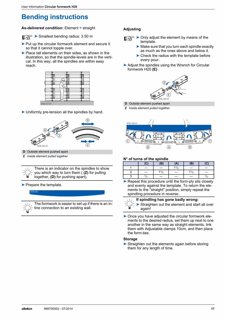
Bending instructionsAs-delivered condition: Element = straight
➤ Put up the circular formwork element and secure it so that it cannot topple over.
➤ Place tall elements on their sides, as shown in the illustration, so that the spindle-levels are in the verti-cal. In this way, all the spindles are within easy reach.
➤ Uniformly pre-tension all the spindles by hand.
➤ Prepare the template.
Adjusting
➤ Adjust the spindles using the Wrench for Circular formwork H20 (E) .
N° of turns of the spindle
➤ Repeat this procedure until the form-ply sits closely and evenly against the template. To return the ele-ments to the "straight" position, simply repeat the spindling procedure in reverse.
➤ Once you have adjusted the circular formwork ele-ments to the desired radius, set them up next to one another in the same way as straight elements, link them with Adjustable clamps 10cm, and then place the form-ties.
Storage➤ Straighten out the elements again before storing
them for any length of time.
☞ ➤ Smallest bending radius: 3.50 m
D Outside element pushed apartZ Inside element pulled together
There is an indicator on the spindles to show you which way to turn them ( (Z) for pulling together, (D) for pushing apart).
The formwork is easier to set up if there is an in-line connection to an existing wall.
9705-217-01
9705-202-01
D
Z
D
Z
9705-001
☞ ➤ Only adjust the element by means of the template.
➤ Make sure that you turn each spindle exactly as much as the ones above and below it.
➤ Check the radius with the template before every pour.
D Outside element pushed apartZ Inside element pulled together
(C) (B) (A) (B) (C) 1 — — 11/2 — —2 — 11/2 — 11/2 —3 1/2 — — — 1/2
If spindling has gone badly wrong:➤ Straighten out the element and start all over
again!
9705-203-01
D
Z
E
9705-204-01
AB B
C C

18 999705002 - 07/2014
User Information Circular formwork H20
Plumbing accessories
Plumbing accessories brace the formwork against wind loads and make it easier to plumb and align.
Permitted spacings [m] of the plumbing accesso-ries:
The values apply where the wind pressure we = 0.65 kN/m2. This results in a dynamic pressure qp = 0.5 kN/m2 (102 km/h) where cp, net = 1.3. The greater wind loads encountered at exposed formwork-ends must be constructionally sustained by additional plumb-ing accessories (e.g. struts or pipe-braces). In cases where higher wind pressure is encountered, the num-ber of struts must be determined by statical calculation.
Note:Every gang-form must be supported by at least 2 plumbing accessories.
Example: For a formwork height of 7.20 m, the following items are required for each element: ▪ 1 Panel strut 540 ▪ 1 Eurex 60 550 or Adjustable plumbing strut
Fixing the struts to the formwork
Fixing to the ground
➤ Anchor the plumbing accessories in such a way as to resist tensile and compressive forces!
Drilled holes in the footplates
a ... diam. 26 mm b ... diam. 18 mm c ... diam. 28 mm d ... diam. 18 mm e ... slotted hole diam. 18x38 mm f ... diam. 35 mm
☞ Important note:The formwork panels must be held stable in every phase of the construction work!Please observe all applicable safety regula-tions!
For more information (wind loads etc.) see the section headed 'Vertical and horizontal loads' in the Calculation Guide 'Doka formwork engi-neering'.
Formwork height [m]Panel strut
Eurex 60 550 orAdjustable plumb-
ing strut340 540
3,00 2,503,60 2,504,20 2,504,80 2,505,40 2,506,00 2,506,60 1,257,20 2,50 2,507,80 2,50 2,50
9705-201-01
For more information, see the Calculation Guide "Wind loads to the Eurocodes" or ask your Doka technician!
A Panel strut 340 IB or 540 IBB Prop head RD EB
Panel struts Eurex 60 550 Adjustable plumb-ing strut
Anchor x2!
9705
-225
-01
B
A
a
9727-343-01
b
9745-214-01
cdd
9727-344-01
fe

User Information Circular formwork H20
19999705002 - 07/2014
Anchoring the footplate
The Doka Express anchor can be re-used many times over - the only tool needed for screwing it in is a ham-mer.
Panel struts
... approx. 60°
A Doka Express anchor 16x125mmB Doka coil 16mm
Characteristic cube compressive strength of the con-crete (fck,cube): min. 25 N/mm2 or 250 kg/cm2 (C20/25 grade concrete)
Follow the Fitting Instructions!
Required safe working load of alternative anchors for foot-plates: Rd 20.3 kN (Fpermissible 13.5 kN)Follow the manufacturer's applicable fitting instruc-tions.
TR632-201-01
A
B
Product features: ▪ Can be telescoped in 8 cm increments ▪ Fine adjustment by screw-thread ▪ All parts are captively integrated - including the tel-
escopic tube (has safety stop to prevent dropout)
Panel strut 340 Panel strut 540
a ... 190.8 - 341.8 cmb ... 119.4 - 178.8 cm
a ... 310.5 - 549.2 cmb ... 224.1 - 274.9 cm
A Panel strut 340 IB or 540 IBB Prop head RD EB
�
9705
-220
-01
a
b
A
B
B
9705
-219
-01
a
b
�
A
B
B

20 999705002 - 07/2014
User Information Circular formwork H20
Eurex 60 550 used as a shoring & plumbing accessory
b ... min. 360.8 cm - max. 602.1 cm ... approx. 60°
Product features: ▪ For shoring high wall formwork ▪ The "Adjusting strut 540 Eurex 60 IB" makes han-
dling much easier, especially when the formwork is being transferred.
▪ Can be telescoped in 10 cm increments ▪ Continuous fine adjustment by screw-thread
Follow the directions in the "Eurex 60 550" User Information!
A Plumbing strut Eurex 60 550B Extension Eurex 60 2.00mC Connector Eurex 60 IBD Plumbing strut shoe Eurex 60 EBE Adjusting strut 540 Eurex 60 IBF Prop head RD EB
Universal dismantling toolThe easy way to turn the spindle nuts.
A good rule of thumb here is:
The length of the shoring & plumbing accessory (i.e. the complete Eurex 60 550 plumbing-strut assembly) = the height of the element to be shored.
9705
-224
-01
D
E
A
B
b
F
C
��
F
Type
Leng
th e
xten
ded
L [m
]
Plu
mbi
ng s
trut E
urex
60
550
(A)
Ext
ensi
on E
urex
60
2.00
m (B
)
Con
nect
or E
urex
60
IB (C
)
Plu
mbi
ng s
trut s
hoe
Eur
ex 6
0 E
B (D
)
Adj
ustin
g st
rut 5
40 E
urex
60
IB (E
)
Pro
p he
ad R
D E
B (F
)
Wei
ght [
kg]
1 3,79 - 5,89 1 --- 1 1 1 2 88,72 5,79 - 7,89 1 1 1 1 1 2 106,7

User Information Circular formwork H20
21999705002 - 07/2014
Adjustable plumbing strut
... approx. 60°See table below for required numbers and types of intermediate pieces
Design loads
1 ... Permitted axial load under tension = 40 kN
Items needed
1 ... Included with product
A Plumbing strut fixing part RDB Spacer bolt, complete (for connecting the Plumbing strut fixing
part to the spindle element)C Spindle element without end-hingeD Intermediate piece 2.40mE Intermediate piece 3.70mF Spindle element with end-hinge
Universal dismantling toolThe easy way to turn the spindle nuts.
9705
-221
-01
E D
B A
C
F��
A good rule of thumb here is:
The length of the Adjustable plumbing strut should be the same as the height of the formwork to be sup-ported.
Type Length L [m]Perm. axial load [kN] under com-
pression 1)
min. L half L max. L1 6.0 - 7.4 40.0 40.0 27.82 7.1 - 8.5 40.0 38.2 24.3
Type
Spi
ndle
ele
men
t with
en
d-hi
nge
Intermediate pieces
Spi
ndle
ele
men
t with
out
end-
hing
eP
lum
bing
stru
t fix
ing
part
RD
Spa
cer b
olt
(com
plet
e)H
exag
on s
crew
s M
16 x
60
8.8
Nut
M16
8
Spr
ing
was
her A
16 1
)
Wei
ght [
kg]
Short2.40 m
Long3.70 m
1 1 — 1 1 1 1 8 153.92 1 2 — 1 1 1 12 183.7

22 999705002 - 07/2014
User Information Circular formwork H20
Pouring platforms with single bracketsDoka brackets can be used to make pouring platforms that can easily be assembled by hand.
Universal bracket 90
"Use-anywhere" brackets for making working plat-forms.
a ... 28.4 cm (50.5 cm in the case of 3.00m high elements)b ... 87 cmh ... 160 cm
Deck and guardrail boards
Board thicknesses for support centres of up to 2.50 m: ▪ Deck-boards min. 20x5 cm ▪ Guard-rail boards min. 20x3 cm, otherwise detailed
dimensioning to EN 12811.Deck and guardrail boards: Per 1 metre length of platform, 0.9 m2 of floor decking and 0.8 m2 of guard-rail boards are needed (in-situ).Fastening the floor decking: with 5 square bolts M 10x70 and 1 square bolt M10x180 per bracket (included with product).Fastening the guard-rail boards: Use nails
Note:The plank and board thicknesses given here comply with the C24 category of EN 338.Observe all national regulations applying to deck-boards and guard-rail boards.
Using scaffolding tubes
Tools: Fork spanner 22 for mounting the couplers and scaffolding tubes.
Preconditions for use:
Only fix the pouring platform onto formwork construc-tions that are sufficiently stable to transfer the expected loads.
Shore the formwork in a windproof manner when erecting it and when it is temporarily placed in the standing position.
Ensure that the formwork gang has sufficient stiff-ness.
Observe all applicable safety regulations.
☞ The brackets must be secured against acciden-tal lift-out
Permitted service load: 1.5 kN/m2 (150 kg/m2)Load Class 2 to EN 12811-1:2003Max. influence width: 2.00 m
CAUTION➤ In the case of H20 N and P Doka beams
where the first drilled hole is 5 cm from the end of the beam, it is not allowed to fix the bracket in the top hole in the beam!
9705
-223
-01
a
b h
A Screw-on couplers 48mm 95B Scaffolding tube 48.3mm
9705
-226
-01
A
B

User Information Circular formwork H20
23999705002 - 07/2014
Top scaffold bracket L
Lightweight bracket for making working platforms.
a ... 76 cm (22.5 cm in the case of 3.00m high elements)b ... 62 cm h ... 115 cm
Deck and guardrail boards
Board thicknesses for support centres of up to 2.50 m: ▪ Deck-boards min. 20x5 cm ▪ Guard-rail boards min. 20x3 cm, otherwise detailed
dimensioning to EN 12811.Deck and guardrail boards: Per 1 metre length of platform, 0.65 m2 of floor decking and 0.6 m2 of guard-rail boards are needed (in-situ).Fastening the floor decking: with 3 square bolts M 10x120 per bracket (not included with product).Fastening the guard-rail boards: Use nails
Note:The plank and board thicknesses given here comply with the C24 category of EN 338.Observe all national regulations applying to deck-boards and guard-rail boards.
Using scaffolding tubes
Tools: Fork spanner 22 for mounting the couplers and scaffolding tubes.
Intermediate platforms
Because there are holes drilled in the beams beneath every spindle level, it is possible to erect several plat-form levels on the Circular formwork element H20, from an element height of 1.20 m upwards.
Permitted service load: 1.5 kN/m2 (150 kg/m2)Load Class 2 to EN 12811-1:2003Max. influence width: 2.00 m
CAUTION➤ In the case of H20 N and P Doka beams
where the first drilled hole is 5 cm from the end of the beam, it is not allowed to fix the bracket in the top hole in the beam!
9705
-222
-01
a
b
h
A Scaffold tube connectorB Scaffolding tube 48.3mmC Screw-on couplers 48mm 50D Hexagon screw M14x40 + hexagon nut M14 (not included with
product)
9705-227-01
A
B
D
C
9705
-228
-01

24 999705002 - 07/2014
User Information Circular formwork H20
Ladder systemThe Ladder system XS permits safe vertical access to and from the intermediate platforms and pouring plat-forms: ▪ when attaching/detaching the formwork to/from the
crane tackle ▪ when opening/closing the formwork ▪ when placing the reinforcement ▪ during pouring
Note:The Ladder system XS must be implemented in such a way that all national regulations are complied with.On formworks of up to 3.00 m in height, no Ladder sys-tem XS is possible.
Assembly instructions
Preparing the formwork
➤ Pre-assemble gang-forms face-down on an assem-bly bench.
➤ With the gang-form still flat, mount platforms and panel struts to it.
Attaching connectors to the formwork
➤ Place the "Connector XS wall formwork" against the frame profile near the top of the formwork.
➤ Fasten the "Connector XS wall formwork" to the frame profile using two Quick acting clamps RU.
➤ Place a "Connector XS wall formwork" against the frame profile, near the bottom of the formwork.
➤ Fasten the "Connector XS wall formwork" to the frame profile using two Quick acting clamps RU.
➤ For formwork heights above 5.85 m, an extra "Con-nector XS wall formwork" must be attached in the same way near the middle of the formwork (i.e. approx. half-way up).This extra connector prevents the ladder swaying when site crew climb up or down it.
WARNING➤ The Ladders XS may only be used as part of
the XS system, and must NOT be used sep-arately (as "lean-to" ladders).
9705
-228
-01
☞ ➤ Do not oil or grease wedge-clamped joins.
A Connector XS wall formworkB Quick acting clamps RU
A Connector XS wall formworkB Quick acting clamps RU
9705
-229
-01
A
B
9705
-229
-02
A
B

User Information Circular formwork H20
25999705002 - 07/2014
Fixing the ladder
to the top "Connector XS wall formwork"➤ Pull out the push-in bolt, and pivot the two safety
hooks out of the way.➤ Place the System ladder XS 4.40m onto the Connec-
tor XS, with the hooking brackets facing downwards.➤ Close the safety hooks.➤ Insert the push-in bolt into whichever rung of the lad-
der is suitable for the height of the formwork, and secure it with a linch pin.
- in the front position (a)
to the bottom "Connector XS wall formwork"➤ Pull out the push-in bolt, pivot both safety hooks out
of the way, and place the ladder onto the Connector XS.
➤ Close the safety hooks, re-insert the push-in bolt and secure it with a linch pin.
– in the front position (a) for one single ladder– in the rear position (b) in the telescoping zone (for 2 ladders)
➤ Mount the Securing barrier XS to the ladder, with fix-ing hooks and wing-nuts.
The components needed for mounting the Securing barrier XS are captively attached to it.
Ladder system XS for heights above 3.75 m
Telescoping ladder extension (for adjusting to ground level)➤ To telescope the ladders past one another, lift the
safety latch on the ladder and fix the Ladder exten-sion XS 2.30m onto the desired rung of the other lad-der.
Close-up
A telescoping join between two Ladder extensions XS 2.30m can be made in the same way.
A Push-in boltB Safety hooksC System ladder XS 4.40m
B Safety hooksC Ladder XS
9705-230-01
aA
B
C
9705
-230
-02
a
B
Cb
D Securing barrier XS
A System ladder XS 4.40mB Ladder extension XS 2.30mC Safety latch
9764-256-01
D
Tr625-201-04
CA
B
Tr625-201-03
CB

26 999705002 - 07/2014
User Information Circular formwork H20
Permanently fixed ladder extension➤ Insert the Ladder extension XS 2.30m into the
uprights of the System ladder XS 4.40m, with its hooking brackets facing downwards, and fasten it. Tighten the screws only very slightly!
Screws (C) are included in the scope of supply of the System ladder XS 4.40m and the Ladder extension XS 2.30m.
Two Ladder extensions XS 2.30m can be fixed together in the same way.
➤ Attach the Ladder cage exit XS (the bottom of the cage must always be at the same height as the plat-form). The safety latches prevent the cage from being accidentally lifted out.
➤ Attach the Ladder cage XS to the next available rung. Attach further ladder cages, in each case to the next available rung.
Items needed
1 ) No allowance made here for intermediate exits.
A System ladder XS 4.40mB Ladder extension XS 2.30mC Screws, width-across 17 mm
☞ Important note:➤ Always observe all relevant safety regula-
tions applying to the use of the Ladder cage XS in the country in which you are operating (e.g. in Germany: BGV D 36).
D Ladder cage exit XSF Safety latch
Tr625-202-01
CA
B
9705-229-03
F
D
E Ladder cage XSF Safety latches (lift-out guard)
Connectors + ladderFormwork height
3.00-3.60 m
>3.60-6.00 m
>6.00-7.20 m
Connector XS wall formwork 2 2 3System ladder XS 4.40m 1 1 1Ladder extension XS 2.30m 0 1 2Framax quick-acting clamp RU 4 4 6
Ladder cageFormwork height
3.00-3.15 m
>3.15-4.05 m
>4.05-5.40 m
>5.40-6.60 m
>6.60-7.20 m
Ladder cage exit XS 1) 1 1 1 1 1
Securing bar-rier XS 1) 1 1 1 1 1
Ladder cage XS 1.00m 1) 0 1 2 3 4
9705-231-01
F
E

User Information Circular formwork H20
27999705002 - 07/2014
Exit onto an intermediate platform
Mounting the Ladder cage XS 0.25m➤ Hook the ladder cage into an empty rung and secure
it against accidental lift-out.
Opposing guard-rail
If there are work platforms mounted on one side of the formwork only, then a fall-protection barrier must be mounted to the opposing formwork.
Basic rule:
▪ The number of "Connectors XS wall formwork" and ladder components is shown in the "Items needed" table.
▪ For each additional exit, one "Ladder cage exit XS" and one "Securing barrier XS" are required.
▪ Any over-large openings above the intermediate exit must be reduced with a Ladder cage XS 0.25m.
9705-228-02
9764-270-019764-269-01
1 2
A Opposing guard-rail (provided at site)
9705
-232
-01
A

28 999705002 - 07/2014
User Information Circular formwork H20
ResettingThe slinging chains are hooked into the ready-mounted lifting-brackets of the Circular formwork element H20.
... max. 15°
Close-up of lifting-bracket:
A Lifting-bracket for Circular formwork H20
Max. load per lifting-bracket: 1000 kg
9705
-205
-01
A
9705-206-01

User Information Circular formwork H20
29999705002 - 07/2014
Determining the required widths of fitting-timberClosure diagram
Insi
de ra
dius
[m]
Wall thickness [m]
A Closure on inside [cm]B Closure on outside [cm]
9705-100
25.0
20.0
15.0
10.0
5.0
3.5
2.5
0 0.2 0.4 0.6 0.8 1.0 1.2
9 8 7 6 5 4 3 2 1 1
2
3
4
5
6
7
8
9
10
0.1 0.3 0.5 0.7 0.9 1.1
4.0
6.0
7.0
8.0
9.0
11.0
12.0
13.0
14.0
16.0
17.0
18.0
19.0
21.0
22.0
23.0
24.0
A
B

30 999705002 - 07/2014
User Information Circular formwork H20
Transporting, stacking and storing
Doka skeleton transport box 1.70x0.80m
Storage and transport devices for small items: ▪ durable ▪ stackableSuitable transport appliances: ▪ crane ▪ pallet stacking truck ▪ forklift truckTo make the "Doka skeleton transport box" easier to load and unload, one of its sidewalls can be opened.
Using Doka skeleton transport boxes 1.70x0.80m as storage units
Max. n° of boxes on top of one another
Using Doka skeleton transport boxes 1.70x0.80m as transport devices
Lifting by crane
Repositioning by forklift truck or pallet stacking truck
The forks can be inserted under either the broadside or the narrowside of the containers.
Utilise the benefits of Doka multi-trip packaging on your site.Multi-trip packaging such as containers, stacking pal-lets and skeleton transport boxes keep everything in place on the site, minimise time wasted searching for parts, and streamline the storage and transport of sys-tem components, small items and accessories.
Max. load: 700 kgPermitted imposed load: 3150 kg
☞ ▪ Multi-trip packaging items that each contain very different loads must be stacked with the heaviest ones at the bottom and the lightest ones at the top!
▪ Rating plate must be in place and clearly leg-ible
Outdoors (on the site) IndoorsFloor gradient up to 3% Floor gradient up to 1%
2 5It is not allowed to stack empty pallets on top of one another!
➤ Only lift the boxes when their sidewalls are closed!
☞ ▪ Multi-trip packaging items may only be lifted one at a time.
▪ Use a suitable lifting chain (e.g. Doka 4-part chain 3.20m). Do not exceed the permitted load-bearing capacity.
▪ Spread-angle max. 30°!
9234-203-01

User Information Circular formwork H20
31999705002 - 07/2014
Doka multi-trip transport box 1.20x0.80m galv.
Storage and transport devices for small items: ▪ durable ▪ stackableSuitable transport appliances: ▪ crane ▪ pallet stacking truck ▪ forklift truck
Multi-trip transport box partition
Different items in the Multi-trip transport box can be kept separate with the Multi-trip transport box partitions 1.20m or 0.80m.
Possible ways of dividing the box
Using Doka multi-trip transport boxes as storage units
Max. n° of boxes on top of one another
Using Doka multi-trip transport boxes as transport devices
Lifting by crane
Repositioning by forklift truck or pallet stacking truck
The forks can be inserted under either the broadside or the narrowside of the containers.
Max. load: 1500 kgPermitted imposed load: 7900 kg
☞ ▪ Multi-trip packaging items that each contain very different loads must be stacked with the heaviest ones at the bottom and the lightest ones at the top!
▪ Rating plate must be in place and clearly leg-ible
A Slide-bolt for fixing the partition
Tr75
5-20
0-02
A
Multi-trip transport box partition Lengthways Crossways
1.20m max. 3 partitions -0.80m - max. 3 partitions
Outdoors (on the site) IndoorsFloor gradient up to 3% Floor gradient up to 1%
3 6It is not allowed to stack empty pallets on top of one another!
☞ ▪ Multi-trip packaging items may only be lifted one at a time.
▪ Use a suitable lifting chain (e.g. Doka 4-part chain 3.20m). Do not exceed the permitted load-bearing capacity.
▪ Spread-angle max. 30°!
Tr755-200-04 Tr755-200-05
9206-202-01

32 999705002 - 07/2014
User Information Circular formwork H20
Doka stacking pallet 1.55x0.85m and 1.20x0.80m
Storage and transport devices for long items: ▪ durable ▪ stackableSuitable transport appliances: ▪ crane ▪ pallet stacking truck ▪ forklift truckThe Bolt-on caster set B turns the stacking pallet into a fast and manoeuvrable transport trolley.
Using Doka stacking pallets as storage units
Max. n° of units on top of one another
Using Doka stacking pallets as transport devices
Lifting by crane
Repositioning by forklift truck or pallet stacking truck
Follow the directions in the "Bolt-on castor set B" Operating Instructions!
Max. load: 1100 kgPermitted imposed load: 5900 kg
☞ ▪ Multi-trip packaging items that each contain very different loads must be stacked with the heaviest ones at the bottom and the lightest ones at the top!
▪ Rating plate must be in place and clearly leg-ible
Outdoors (on the site) IndoorsFloor gradient up to 3% Floor gradient up to 1%
2 6It is not allowed to stack empty pallets on top of one another!
☞ ▪ How to use with bolt-on castor set: Always apply the fixing brake when the con-tainer is "parked".When Doka stacking pallets are stacked, the bottom pallet must NOT be one with a bolt-on caster set mounted to it.
☞ ▪ Multi-trip packaging items may only be lifted one at a time.
▪ Use a suitable lifting chain (e.g. Doka 4-part chain 3.20m). Do not exceed the permitted load-bearing capacity.
▪ Load the items centrically. ▪ Fasten the load to the stacking pallet so that
it cannot slide or tip out. ▪ When lifting stacking pallets to which Bolt-on
castor sets B have been attached, you must also follow the directions in these Operating Instructions!
▪ Spread-angle max. 30°!
aDoka stacking pallet 1.55x0.85m max. 4.0 mDoka stacking pallet 1.20x0.80m max. 3.0 m
☞ ▪ Load the items centrically. ▪ Fasten the load to the stacking pallet so that
it cannot slide or tip out.
92815-224-01
a
= =

User Information Circular formwork H20
33999705002 - 07/2014
Doka accessory box
Storage and transport devices for small items: ▪ durable ▪ stackableSuitable transport appliances: ▪ crane ▪ pallet stacking truck ▪ forklift truckThe Doka accessory box is the tidy, easy-to-find way of storing and stacking all interconnection and form-tie components.The Bolt-on caster set B turns the stacking pallet into a fast and manoeuvrable transport trolley.
Doka accessory boxes as storage units
Max. n° of boxes on top of one another
Doka accessory box as transport devices
Lifting by crane
Repositioning by forklift truck or pallet stacking truck
The forks can be inserted under either the broadside or the narrowside of the containers.
Bolt-on castor set B
The Bolt-on caster set B turns the stacking pallet into a fast and manoeuvrable transport trolley.Suitable for drive-through access openings > 90 cm.
The Bolt-on caster set B can be mounted to the follow-ing multi-trip packaging items: ▪ Doka accessory box ▪ Doka stacking pallets
Follow the directions in the "Bolt-on castor set B" Operating Instructions!
Max. load: 1000 kgPermitted imposed load: 5530 kg
☞ ▪ Multi-trip packaging items that each contain very different loads must be stacked with the heaviest ones at the bottom and the lightest ones at the top!
▪ Rating plate must be in place and clearly leg-ible
Outdoors (on the site) IndoorsFloor gradient up to 3% Floor gradient up to 1%
3 6It is not allowed to stack empty pallets on top of one another!
☞ ▪ How to use with bolt-on castor set: Always apply the fixing brake when the con-tainer is "parked".When Doka accessory boxes are stacked, the bottom box must NOT be one with a bolt-on castor set mounted to it.
☞ ▪ Multi-trip packaging items may only be lifted one at a time.
▪ Use a suitable lifting chain (e.g. Doka 4-part chain 3.20m). Do not exceed the permitted load-bearing capacity.
▪ When lifting stacking pallets to which Bolt-on castor sets B have been attached, you must also follow the directions in these Operating Instructions!
▪ Spread-angle max. 30°!
Follow the directions in the Operating Instruc-tions!
92816-206-01

Article n°[kg] Article n°[kg]
34 999705002 - 07/2014
Component overview User Information Circular formwork H20
Component overview[kg]Article n°
Circular formwork element H20 2.40x0.70m 195.0 587820000Circular formwork element H20 2.40x1.20m 244.0 587821000Circular formwork element H20 2.40x2.40m 472.0 587822000Circular formwork element H20 2.40x3.00m 523.0 587813000Circular formwork element H20 2.40x3.60m 699.0 587823000Circular formwork element H20 2.40x4.80m 934.0 587824000Rundschalungselement H20 2,40m
Circular formwork element H20 2.50x0.70m 197.0 587825000Circular formwork element H20 2.50x1.20m 249.0 587826000Circular formwork element H20 2.50x2.40m 480.0 587827000Circular formwork element H20 2.50x3.00m 534.0 587814000Circular formwork element H20 2.50x3.60m 716.0 587828000Circular formwork element H20 2.50x4.80m 942.0 587829000Rundschalungselement H20 2,50m
Stacking plate for circular formwork H20 7.0 587830000Aufstocklasche für Rundschalung H20
Adjustable clamp 10cm 3.7 587808000Ausgleichsspanner 10cm
Framax stop-end tie 1.5 588143000Framax-Stirnanker
Framax multi function clamp 5.8 588169000Framax-Uni-Spanner
Wrench for circular formwork H20 0.70 587807000Schlüssel für Rundschalung H20
Template f. circular formw. H20 ...../.....mm 6.5 177020000Schablone für Rundschalung H20 ...../.....mm
Panel strut 340 IB 24.3 580365000Elementstütze 340 IBconsisting of:(A) Plumbing strut 340 IB 16.7 588696000
GalvanisedLength: 190.8 - 341.8 cm
(B) Adjusting strut 120 IB 7.6 588248500GalvanisedLength: 81.5 - 130.6 cm
Panel strut 540 IB 41.4 580366000Elementstütze 540 IBconsisting of:(A) Plumbing strut 540 IB 30.7 588697000
GalvanisedLength: 310.5 - 549.2 cm
(B) Adjusting strut 220 IB 10.9 588251500GalvanisedLength: 172.5 - 221.1 cm
GalvanisedHeight: 62 cm
GalvanisedLength: 30 cm
GalvanisedLength: 29 cm
GalvanisedLength: 40 cm
GalvanisedLength: 27 cm
Weight per m²Project-specific!
GalvanisedDelivery condition: folded closed
GalvanisedDelivery condition: folded closed
A
B
A
B

Article n°[kg] Article n°[kg]
35999705002 - 07/2014
User Information Circular formwork H20 Component overview
Eurex 60 550Eurex 60 550depending on length, comprising:(A) Plumbing strut Eurex 60 550 42.5 582658000
Powder-coated, blueAluminiumLength: 343 - 553 cm
(B) Extension Eurex 60 2.00m 21.3 582651000Powder-coated, blueAluminiumLength: 250 cm
(C) Connector Eurex 60 IB 4.2 582657500GalvanisedLength: 15 cmWidth: 15 cmHeight: 30 cm
(D) Plumbing strut shoe Eurex 60 EB 8.0 582660500GalvanisedLength: 31 cmWidth: 12 cmHeight: 33 cm
(E) Adjusting strut 540 Eurex 60 IB 27.8 582659500GalvanisedLength: 303.5 - 542.2 cm
Prop head RD EB 1.9 587806000Stützenkopf RD EB
Adjustable plumbing strutRohrstützedepending on length, comprising:(A) Prop head RD EB 1.9 587806000
GalvanisedLength: 19 cmWidth: 8 cm
(B) Distance bolt compl. for spindle head 0.43 504322002(C) Spindle element without end-hinge 30.6 584316000(D) Extension strut 3.70m 80.0 584318000(E) Extension strut 2.40m 54.6 584317000(F) Spindle element with end-hinge 38.4 584315000
Universal dismantling tool 3.7 582768000Universal-Lösewerkzeug
Doka express anchor 16x125mm 0.31 588631000Doka-Expressanker 16x125mm
Doka coil 16mm 0.009 588633000Doka-Coil 16mm
Universal bracket 90 30.4 580476000Universal-Konsole 90
Delivery condition: separate parts
GalvanisedLength: 19 cmWidth: 8 cm
A
B
C
D
E
Painted blueDelivery condition: separate parts
GalvanisedLength: 75.5 cm
GalvanisedLength: 18 cmFollow fitting instructions!
GalvanisedDiameter: 1.6 cm
GalvanisedLength: 121 cmHeight: 235 cm
AB
C
D
E
F

Article n°[kg] Article n°[kg]
36 999705002 - 07/2014
Component overview User Information Circular formwork H20
Top scaffold bracket L 12.6 587153500Betonierkonsole L
Top scaffold bracket L painted 12.0 587153000Betonierkonsole L lackiert
Scaffold tube 48.3mm 0.50m 1.7 682026000Scaffold tube 48.3mm 1.00m 3.6 682014000Scaffold tube 48.3mm 1.50m 5.4 682015000Scaffold tube 48.3mm 2.00m 7.2 682016000Scaffold tube 48.3mm 2.50m 9.0 682017000Scaffold tube 48.3mm 3.00m 10.8 682018000Scaffold tube 48.3mm 3.50m 12.6 682019000Scaffold tube 48.3mm 4.00m 14.4 682021000Scaffold tube 48.3mm 4.50m 16.2 682022000Scaffold tube 48.3mm 5.00m 18.0 682023000Scaffold tube 48.3mm 5.50m 19.8 682024000Scaffold tube 48.3mm 6.00m 21.6 682025000Scaffold tube 48.3mm .....m 3.6 682001000Gerüstrohr 48,3mm
Scaffold tube connection 0.27 584375000Gerüstrohranschluss
Screw-on coupler 48mm 50 0.84 682002000Anschraubkupplung 48mm 50
Doka 4-part chain 3.20m 15.0 588620000Doka-Vierstrangkette 3,20m
Framax fitting timber 2x12cm 2.70m 3.1 176020000Framax fitting timber 3x12cm 2.70m 4.7 176022000Framax fitting timber 5x12cm 2.70m 7.8 176024000Framax fitting timber 10x12cm 2.70m 15.5 176026000Framax-Passholz 2,70m
Reversible ratchet 1/2" 0.73 580580000Umschaltknarre 1/2"
Box nut 24 1/2" 0.12 580584000Stecknuss 24 1/2"
Ladder system XS
Connector XS Wall formwork 20.8 588662000Anschluss XS Wandschalung
Framax quick acting clamp RU 3.3 588153400Framax-Schnellspanner RU
System ladder XS 4.40m 33.2 588640000System-Leiter XS 4,40m
GalvanisedLength: 101 cmHeight: 159 cm
Painted blueLength: 101 cmHeight: 159 cm
Galvanised
GalvanisedHeight: 7 cm
GalvanisedWidth-across: 22 mmFollow fitting instructions!
Follow the directions in the "Operat-ing Instructions"!
Varnished yellow
GalvanisedLength: 30 cm
GalvanisedWidth: 89 cmHeight: 63 cm
GalvanisedLength: 20 cm
Galvanised
Article n°[kg] Article n°[kg]
37999705002 - 07/2014
User Information Circular formwork H20 Component overview
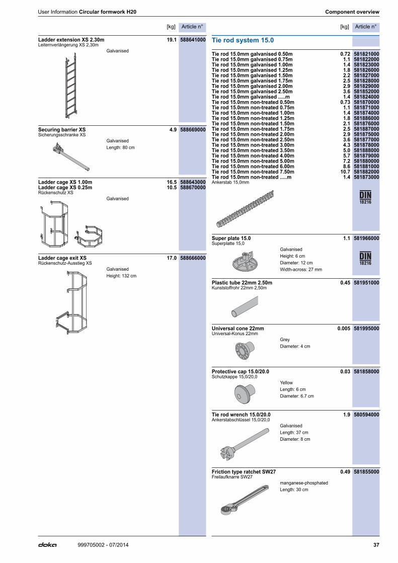
Ladder extension XS 2.30m 19.1 588641000Leiternverlängerung XS 2,30m
Securing barrier XS 4.9 588669000Sicherungsschranke XS
Ladder cage XS 1.00m 16.5 588643000Ladder cage XS 0.25m 10.5 588670000Rückenschutz XS
Ladder cage exit XS 17.0 588666000Rückenschutz-Ausstieg XS
Tie rod system 15.0
Tie rod 15.0mm galvanised 0.50m 0.72 581821000Tie rod 15.0mm galvanised 0.75m 1.1 581822000Tie rod 15.0mm galvanised 1.00m 1.4 581823000Tie rod 15.0mm galvanised 1.25m 1.8 581826000Tie rod 15.0mm galvanised 1.50m 2.2 581827000Tie rod 15.0mm galvanised 1.75m 2.5 581828000Tie rod 15.0mm galvanised 2.00m 2.9 581829000Tie rod 15.0mm galvanised 2.50m 3.6 581852000Tie rod 15.0mm galvanised .....m 1.4 581824000Tie rod 15.0mm non-treated 0.50m 0.73 581870000Tie rod 15.0mm non-treated 0.75m 1.1 581871000Tie rod 15.0mm non-treated 1.00m 1.4 581874000Tie rod 15.0mm non-treated 1.25m 1.8 581886000Tie rod 15.0mm non-treated 1.50m 2.1 581876000Tie rod 15.0mm non-treated 1.75m 2.5 581887000Tie rod 15.0mm non-treated 2.00m 2.9 581875000Tie rod 15.0mm non-treated 2.50m 3.6 581877000Tie rod 15.0mm non-treated 3.00m 4.3 581878000Tie rod 15.0mm non-treated 3.50m 5.0 581888000Tie rod 15.0mm non-treated 4.00m 5.7 581879000Tie rod 15.0mm non-treated 5.00m 7.2 581880000Tie rod 15.0mm non-treated 6.00m 8.6 581881000Tie rod 15.0mm non-treated 7.50m 10.7 581882000Tie rod 15.0mm non-treated .....m 1.4 581873000Ankerstab 15,0mm
Super plate 15.0 1.1 581966000Superplatte 15,0
Plastic tube 22mm 2.50m 0.45 581951000Kunststoffrohr 22mm 2,50m
Universal cone 22mm 0.005 581995000Universal-Konus 22mm
Protective cap 15.0/20.0 0.03 581858000Schutzkappe 15,0/20,0
Tie rod wrench 15.0/20.0 1.9 580594000Ankerstabschlüssel 15,0/20,0
Friction type ratchet SW27 0.49 581855000Freilaufknarre SW27
Galvanised
GalvanisedLength: 80 cm
Galvanised
GalvanisedHeight: 132 cm
GalvanisedHeight: 6 cmDiameter: 12 cmWidth-across: 27 mm
GreyDiameter: 4 cm
YellowLength: 6 cmDiameter: 6.7 cm
GalvanisedLength: 37 cmDiameter: 8 cm
manganese-phosphatedLength: 30 cm

Article n°[kg] Article n°[kg]
38 999705002 - 07/2014
Component overview User Information Circular formwork H20
Box spanner 27 0.65m 1.9 581854000Steckschlüssel 27 0,65m
Multi-trip packaging
Doka skeleton transport box 1.70x0.80m 87.0 583012000Doka-Gitterbox 1,70x0,80m
Doka multi-trip transport box 1.20x0.80m 75.0 583011000Doka-Mehrwegcontainer 1,20x0,80m
Multi-trip transport box partition 0.80m 3.7 583018000Multi-trip transport box partition 1.20m 5.5 583017000Mehrwegcontainer Unterteilung
Doka stacking pallet 1.55x0.85m 42.0 586151000Doka-Stapelpalette 1,55x0,85m
Doka stacking pallet 1.20x0.80m 39.5 583016000Doka-Stapelpalette 1,20x0,80m
Doka accessory box 106.4 583010000Doka-Kleinteilebox
Bolt-on castor set B 33.6 586168000Anklemm-Radsatz B
Galvanised
GalvanisedHeight: 113 cm
GalvanisedHeight: 78 cm
Timber parts varnished yellowSteel parts galvanised
GalvanisedHeight: 77 cm
GalvanisedHeight: 77 cm
Timber parts varnished yellowSteel parts galvanisedLength: 154 cmWidth: 83 cmHeight: 77 cm
Painted blue

User Information Circular formwork H20 Component overview
39999705002 - 07/2014

999705002 - 07/2014Doka GmbH | Josef Umdasch Platz 1 | 3300 Amstetten | Austria | T +43 7472 605-0 | F +43 7472 66430 | [email protected] | www.doka.com
Near to you, worldwide
Doka is one of the world leaders in developing, manu-facturing and distributing formwork technology for use in all fields of the construction sector.With more than 160 sales and logistics facilities in over 70 countries, the Doka Group has a highly efficient dis-tribution network which ensures that equipment and
technical support are provided swiftly and profession-ally.An enterprise forming part of the Umdasch Group, the Doka Group employs a worldwide workforce of more than 5600.