The Flasher
11
By
-
Upload
jordan-rogers -
Category
Documents
-
view
137 -
download
6
description
The Flasher. By. The Flasher Circuit and Components. Power Diode. Resistors. LEDs. 9V Battery. Electrolytic Capacitors. NPN Transistors. 9V Battery. - PowerPoint PPT Presentation
Transcript of The Flasher

By

Power Diode
LEDs
Resistors
NPN Transistors
Electrolytic Capacitors
9V Battery

Batteries contain chemicals which react with one another to create a pushing force also know as voltage. Batteries have to be connected the right way to work, components like this are said to be polarised.
Symbol for a 9v battery

A power diode is like a 1 way valve, it prevents current from flowing back the way it came and damaging circuit components. It has 2 leads, an anode and a cathode. The anode is made from a material called P type. The cathode is made from an N type material. The P type material has 7 electrons so it will want to gain an electron, because its missing an electron its said to have a hole. The N type material has 9 electrons so it will lose an electron easily as it has 1 extra flowing electron. Like the battery this component is also polarised and has to be placed into the circuit correctly.
Diode Symbol
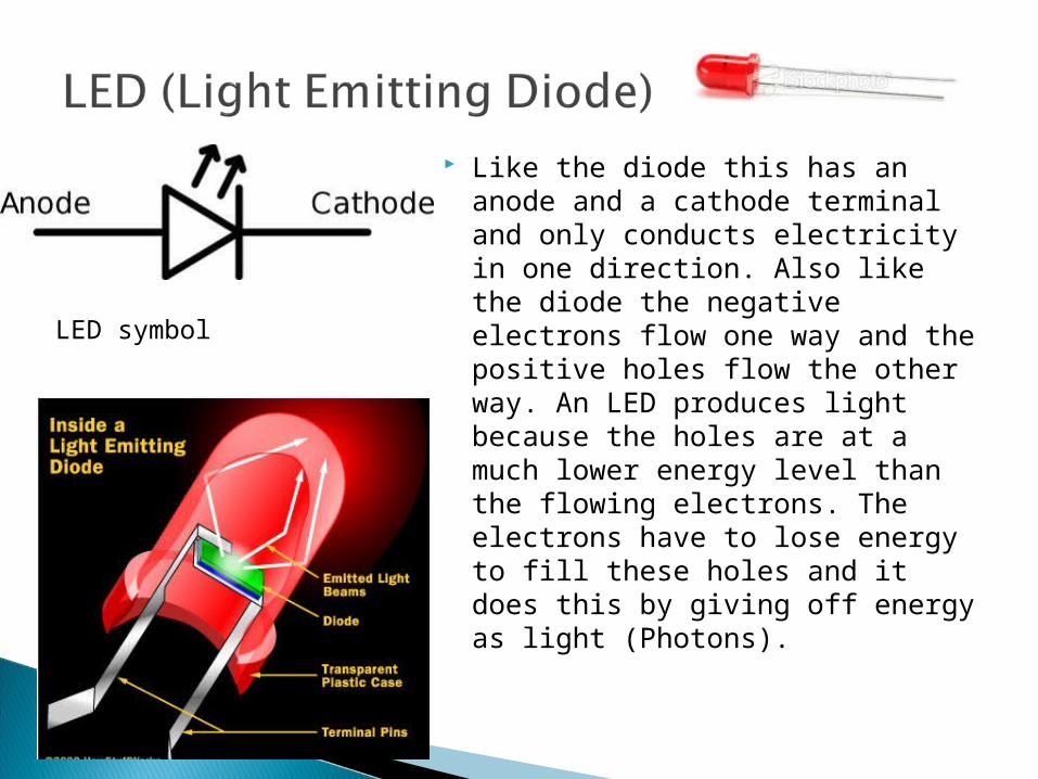
Like the diode this has an anode and a cathode terminal and only conducts electricity in one direction. Also like the diode the negative electrons flow one way and the positive holes flow the other way. An LED produces light because the holes are at a much lower energy level than the flowing electrons. The electrons have to lose energy to fill these holes and it does this by giving off energy as light (Photons).
LED symbol
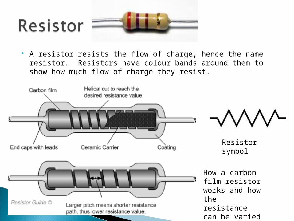
A resistor resists the flow of charge, hence the name resistor. Resistors have colour bands around them to show how much flow of charge they resist.
Resistor symbol
How a carbon film resistor works and how the resistance can be varied
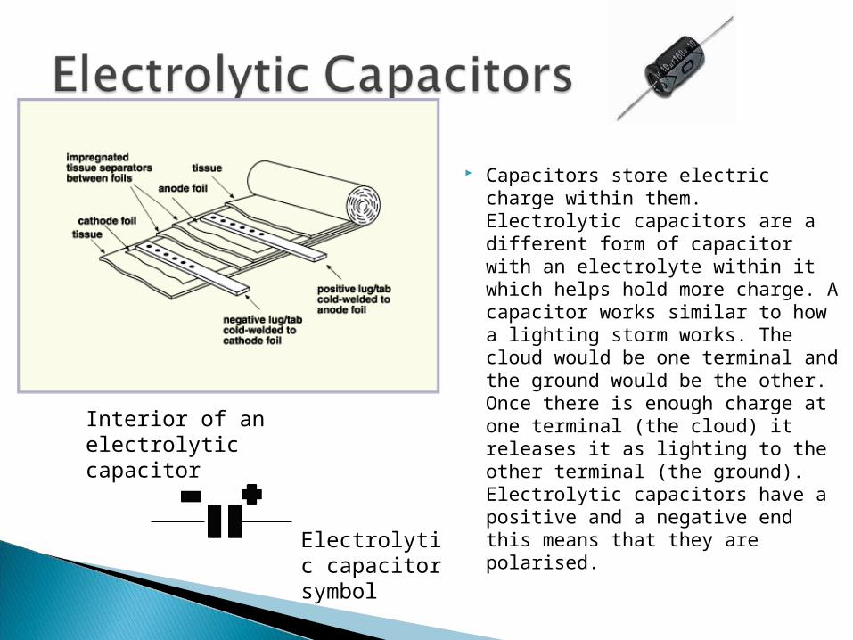
Capacitors store electric charge within them. Electrolytic capacitors are a different form of capacitor with an electrolyte within it which helps hold more charge. A capacitor works similar to how a lighting storm works. The cloud would be one terminal and the ground would be the other. Once there is enough charge at one terminal (the cloud) it releases it as lighting to the other terminal (the ground). Electrolytic capacitors have a positive and a negative end this means that they are polarised.
Electrolytic capacitor symbol
Interior of an electrolytic capacitor

An NPN Transistor is similar to diode is built as the NPN means its N type material, P type material and then N type material.
A transistor is like a switch, it has 3 leads on it: The collector, the base and the emitter. A transistor is classified as off, if no current is flowing through the base. This is because the base is what allows current to flow from the collector to the emitter.
Transistor can also be used as an amplifier because when the base has a current flowing through it, it also allows the collector to have current flow through it and both of these currents flow out the emitter. So you can add the charge from the base with collector and this will what is being emitted.
NPN Transistor symbol

When the circuit is complete and on, the capacitors will begin to charge. They charge at different rates because no component is made the same. Charging one capacitor will cause the current to flow through the base of the transistor opposite that capacitor. When the capacitor discharges through the base of its opposite transistor, that transistor turns on. When that transistor is on it prevents the capacitor attached to its collector from charging.
When the other capacitor is fully charged the transistor turns off and allows the other capacitor to discharge through the resistor.
The cycle repeats its self many times per second.
Every time a transistor turns on in this circuit the LED between it and the positive power supply turns on.

Some of the uses for a circuit like this are; railroad crossings, emergency vehicle lights and Christmas lights.
The time the LEDs stay lit for can be changed by using different resistors or capacitors.
Resistor change how long it takes for the charge to reach the components of the circuit and the capacitors change how much charge is needed before it will be discharged.

http://www.ami.ac.uk/courses/topics/0136_ec/ Date accessed 10/9/13 http://www.resistorguide.com/carbon-film-resistor/ Date accessed 12/9/13 By Resistor Guide http://www.capacitorguide.com/electrolytic-capacitor/ Date accessed By 12/9/13 By Capacitor Guide http://www.resistorguide.com/fixed-resistor/ Date accessed 12/9/13 By Resistor Guide http://www.resistorguide.com/what-is-a-resistor/ Date accessed 12/9/13 By Resistor Guide http://www.resistorguide.com/resistance-of-a-resistor/ Date accessed 12/9/13 Resistor Guide http://electronics.howstuffworks.com/led1.htm Date accessed 9/9/13 by HowStuffWorks http://electronics.howstuffworks.com/capacitor.htm Date accessed 9/9/13by HowStuffWorks http://electronics.howstuffworks.com/capacitor1.htm Date accessed 9/9/13 by HowStuffWorks http://electronics.howstuffworks.com/transistor.htm Date accessed 9/9/13 by HowStuffWorks http://www.instructables.com/id/How-Electronic-Switches-Work-For-Noobs-Relays-and/step5/How-a-
Does-a-Transistor-Work/ Date accessed 10/9/13 By Instructables http://electronics.howstuffworks.com/led2.htm Date accessed 10/9/13 By HowStuffWorks FUNWAY into Electronics volume 1 By Dick Smiths Electronics, Published 1994 Physics Teacher Edmodo 5/9/13