
The Extended Echo Ranging Aural and Visual Support · PDF fileEXTENDED ECHO RANGING AURAL AND...
12
JOHNS HOPKINS APL TECHNICAL DIGEST, VOLUME 18, NUMBER 1 (1997) 113 T The Extended Echo Ranging Aural and Visual Support Trainer Andrew C. Coon, Christopher A. Ross, Robert W. Chalmers, and Peter C. Gallati he Extended Echo Ranging (EER) Aural and Visual Support Trainer (AVST) provides signal recognition training for Navy aviation warfare systems operators. EER is an air-deployed active multisensor acoustic system designed for P-3C aircraft. The active system relies on the detection of submarine echoes generated by reflected impulsive acoustic energy generated by underwater sources commanded by the aircraft. Operators, monitoring multiple sonobuoy receivers, attempt to classify any detected echoes. Target recognition, a key element to the success of an EER mission, is complicated by the detection of nontarget echoes, independently generated acoustic transients, and system-induced electrical pops. The AVST provides a database of recorded real-world EER signals tied to automated testing that progressively challenges the operators as their measured proficiency increases. The training software package is hosted on a Navy standard personal computer system and is currently being widely distributed to all patrol aviation squadrons and their associated naval commands. (Keywords: Air antisubmarine warfare, Extended Echo Ranging, Sonar.) INTRODUCTION The Extended Echo Ranging (EER) Aural and Visual Support Trainer (AVST) is an APL-developed desktop computer training system dedicated to training sonar operators in signal recognition. EER is an air- deployed, active multisensor sonar system hosted on a P-3C aircraft. The system emerged in response to the deployment of increasingly quiet Soviet submarines in the late 1970s and 1980s that began to challenge tra- ditionally reliable passive systems. 1 As Fig. 1 illustrates, to detect a submarine (target), the aircraft deploys a distributed field of sonobuoy receivers and sources. The aircraft then commands a source to transmit (ping) a single burst of acoustic energy. Between pings, the onboard operators monitor uplinked acoustic data from several sonobuoys (see the boxed insert). The intent is to detect reflecting source energy from a target, i.e., detect a target echo. Using the arrival time and bearing (enabled by small-aperture, directional hydrophones) of the target echo, the aircraft can localize the target for prosecution if necessary. 2 Before localization, how-
-
Upload
trinhtuyen -
Category
Documents
-
view
223 -
download
3
Transcript of The Extended Echo Ranging Aural and Visual Support · PDF fileEXTENDED ECHO RANGING AURAL AND...

EXTENDED ECHO RANGING AURAL AND VISUAL SUPPORT TRAINER
T
The Extended Echo Ranging Aural and Visual SupportTrainer
Andrew C. Coon, Christopher A. Ross, Robert W. Chalmers, and Peter C. Gallati
he Extended Echo Ranging (EER) Aural and Visual Support Trainer (AVST)provides signal recognition training for Navy aviation warfare systems operators.EER is an air-deployed active multisensor acoustic system designed for P-3C aircraft.The active system relies on the detection of submarine echoes generated byreflected impulsive acoustic energy generated by underwater sources commanded bythe aircraft. Operators, monitoring multiple sonobuoy receivers, attempt to classifyany detected echoes. Target recognition, a key element to the success of an EERmission, is complicated by the detection of nontarget echoes, independentlygenerated acoustic transients, and system-induced electrical pops. The AVSTprovides a database of recorded real-world EER signals tied to automated testingthat progressively challenges the operators as their measured proficiency increases.The training software package is hosted on a Navy standard personal computersystem and is currently being widely distributed to all patrol aviation squadrons andtheir associated naval commands.(Keywords: Air antisubmarine warfare, Extended Echo Ranging, Sonar.)
INTRODUCTIONThe Extended Echo Ranging (EER) Aural and
Visual Support Trainer (AVST) is an APL-developeddesktop computer training system dedicated to trainingsonar operators in signal recognition. EER is an air-deployed, active multisensor sonar system hosted on aP-3C aircraft. The system emerged in response to thedeployment of increasingly quiet Soviet submarines inthe late 1970s and 1980s that began to challenge tra-ditionally reliable passive systems.1 As Fig. 1 illustrates,to detect a submarine (target), the aircraft deploys a
JOHNS HOPKINS APL TECHNICAL DIGEST, VOLUME 18, NUMBER 1 (1
distributed field of sonobuoy receivers and sources. Theaircraft then commands a source to transmit (ping) asingle burst of acoustic energy. Between pings, theonboard operators monitor uplinked acoustic data fromseveral sonobuoys (see the boxed insert). The intent isto detect reflecting source energy from a target, i.e.,detect a target echo. Using the arrival time and bearing(enabled by small-aperture, directional hydrophones)of the target echo, the aircraft can localize the targetfor prosecution if necessary.2 Before localization, how-
997) 113

A. C. COON ET AL.
Figure 1. The Extended Echo Ranging System consists of a P-3C aircraft that deploys a field of sources and receivers. Controlled sourceenergy is intended to acoustically illuminate the target to generate a detectable target echo.
P-3C
Source command
Single pulse source
Target echo
Bathymetry echo
Acoustic data
ever, the operators on board the aircraft must identifythe target echo from among similar, yet discernible,nontarget pulses originating from ocean bottom reflec-tions or other independently generated transients suchas whale chirps or electrical pops generated within thesonobuoy or aircraft electronics.3 To discern a targetecho from nontarget detections, operators listen andlook for signal clues. Timely and accurate signal clas-sification is key to the success of the EER mission. TheAVST bolsters an operator’s ability to classify EERsignals.
The AVST provides an interactive environment inwhich an operator can train with a database of EERsignals collected from at-sea exercises. The databaseconsists of signals from a variety of areas, environments,and seasons. Each signal may be played through head-sets while simultaneously displayed using an emulatedEER classification display. The operator can eithermanually select labeled signals from the database or letthe AVST provide the signals in the form of an auto-mated test. When in testing mode, the operator’s skilllevel improves as he or she translates testing feedbackinto a set of personal rules for signal identification. Astesting proceeds, the AVST accumulates statistical
114 JOH
information on operator performance and signaldifficulty. It is the signal difficulty statistics that providethe means to build tests of varying difficulty.
BACKGROUNDThe AVST originated from analysis at APL dedicated
to exploring tracking and data fusion algorithms in-tended to enhance automatic target recognition forEER (see Coon in this issue). Value-added measure-ments for developed approaches required an under-standing of the operator’s ability to aurally and visuallyclassify a signal. To this end, APL developed a databaseof signals to test operators. Through testing, it becameapparent that performance was strongly related to ex-perience and training. This finding, combined with theNavy’s need for cost-effective training, resulted inAPL’s developing the AVST.
Initial AVST deliveries were hosted by a Sun Sparcsystem that operated in a classroom setting at two patrolaviation commands: Patrol Wing 11 in Florida andPatrol Wings Pacific in Hawaii. The trainer providedaccess to labeled signals in a database that instructorsdisplayed on a large-screen TV or projection screen.
NS HOPKINS APL TECHNICAL DIGEST, VOLUME 18, NUMBER 1 (1997)

EXTENDED ECHO RANGING AURAL AND VISUAL SUPPORT TRAINER
Multiple headsets and speakers provided the audio.This first version was built and delivered in 9 monthsin close coordination with Navy instructors and spe-cialists in Navy operator–machine-interface designfrom the Naval Air Warfare Center at Naval AirStation, Patuxent River, Maryland. In addition totraining new EER crews, the AVST served, and con-tinues to serve, as an analysis tool at the Naval AirWarfare Center and APL for measuring various aspectsof operator performance.
JOHNS HOPKINS APL TECHNICAL DIGEST, VOLUME 18, NUMBER 1 (199
When EER passed its operational testing in the fallof 1995 and became a Fleet asset, the AVST movedfrom the Sun to a less expensive, more widely availableNavy standard personal computer (PC) referred to as theAviation Multifunction Electronic Warfare Trainer(AMEWT). The AMEWT hosts a number of one-on-one software training packages for naval aviation train-ing. The Naval Air Warfare Center Weapons Divisionand PMA-205 in the Naval Air Systems Commandmanage configuration and distribution of the AMEWTs.
P-3C CREW STATIONSThe P-3C aircraft was designed and built to be operated
as an integrated team effort, as illustrated in the figure. Thetactical coordinator (TACCO) is responsible for using ap-propriate tactics to carry out a mission and for coordinatingthe functions of the entire flight crew. The decision toultimately call a target detection and transition to localizationrests with the TACCO. The acoustic sensor operators(sensor 1 and sensor 2) pass bearing and time-of-arrivalinformation of favorably evaluated detections to theTACCO, who uses the information with a geographicaldisplay. The pilot, as aircraft commander, is responsible forall aspects of aircraft safety and coordinates antisubmarinewarfare tactics with the TACCO. The mission commanderof the crew, either the TACCO or the pilot, is responsiblefor all phases of the assigned mission. A copilot and thirdpilot assist the pilot in those responsibilities. The flight
engineer (one or two per crew) performs exterior and inte-rior maintenance checks on the aircraft and monitors en-gine and other system controls during flight. The navigator/communicator (NAV/COMM) operator is responsible foraspects of navigating and performing tactical communica-tions. The nonacoustic sensor operator (sensor 3) is respon-sible for the proper operation of the radar and othernonacoustic sensors. The in-flight technician is responsiblefor in-flight repair of avionics equipment. An observer isalso assigned who is typically in training for a primary crewposition. At least one crew member is ordnance qualified,i.e., responsible for preparing all internally stored armamentand ordnance (ARM/ORD) during a mission. All pilots arequalified naval aviators, and TACCOs and NAV/COMMsare qualified naval flight officers. All other P-3C flight crewpositions are filled by enlisted personnel.
Observer
Acoustic operatorstations
Observer
ARM/ORD station
Technicianstation
TACCOstation
Flightstation
NAV/COMMstation
Nonacousticoperatorstation
7) 115

A. C. COON ET AL.
Currently, there are over 460AMEWTs distributed throughoutthe patrol aviation community. Inaddition to the migration of theAVST from the Sun to the PC,Navy emphasis on self-directedstudy gave rise to the developmentof an automated testing capability.The first AMEWT software buildwith automated testing was distrib-uted to the Fleet in June 1996.
AURAL AND VISUALSUPPORT TRAINERDESCRIPTION
AVST Functional OverviewThe operator invokes the AVST
from a menu of options availableon the AMEWT system and logson. Following logon, the operatorloads signals into the AVST forevaluation from a database of real-world signals. Figure 2 shows themain AVST display. The upper partof this display mimics the P-3CEER signal recall display seen onthe aircraft; the lower part containsAVST controls. The controls arekept simple and easy to learn so that the operator canfocus on developing signal identification skills. The topof the recall display shows an A-scan (amplitude vs.time plot) containing the signal return being evaluated.A white bar above the A-scan highlights the return.Underneath this A-scan is a time-expanded A-scancontaining the signal return. The bottom trace expandsthe signal further in an unprocessed time series format.Figure 2 shows representative data in the display. Thetop two A-scans appear in the selected EER band ofinterest (acoustic data are processed over specific bandsthat depend on the EER environment). The bottomtime series trace is unprocessed and left in the widestfrequency band available to EER. When the signal isactivated for playback with the PLAY button, theexpanded A-scan scrolls into view from left to right andis synchronized with the audio output to the operators’headsets. Immediately after this, the bottom time seriesappears as the signal plays a second time over the short-er interval to emphasize the main portion of the signal.Audio output is played in the widest frequency bandavailable to EER.
Two distinct sets of signals can be loaded into theGroup 1 and Group 2 areas located at the bottom ofthe main display. They come from a database of 500
Figure 2. Aural and Vsignals. The P-3C–emthe signals. The data
116
signals collected from a variety of sea tests around theworld. By clicking one of the LOAD buttons on themain display, the operator activates a database searchtemplate, shown in Fig. 3. Signals are parsed by envi-ronment, area, signal type, and season. Figure 3 showsa database search setting for all target signals, in anyconvergence zone environment, from any area, andfrom any season. Figure 4 illustrates the chain of stepsfollowed at APL to build the AVST database. APLdigitizes multitrack analog tapes and uses various digitalsignal processing tools, along with geographical andsignal analysis display aids, to detect, classify, and ar-chive EER signals.
In addition to the PLAY button, the AVST controlson the main display include an INFO button, whichbrings up displays shown in Fig. 5. These displays showa signal’s characteristics, the sound velocity profile forits ocean environment, and a sonobuoy field plot show-ing the location of the source and receiver. If the signalis a target return, the field plot also shows the target’sposition and bearing. Other options from the maindisplay include FILL/NO FILL and LINEAR/LOG,which are display format controls; AUDIO, which pro-vides volume control; MIX, which randomly mixes theorder of the loaded signal list; and HIDE/SHOW, which
isual Support Trainer (AVST) main display showing a list of loadedulated signal recall display is controlled with AVST functions belowshown are representative of EER signal data.
JOHNS HOPKINS APL TECHNICAL DIGEST, VOLUME 18, NUMBER 1 (1997)

EXTENDED ECHO RANGING AURAL AND VISUAL SUPPORT TRAINER
Figure 3. The operator can select Extended Echo Ranging sig-nals from the database. The signals are partitioned by environ-ment type, area, signal type, and season. The search template isset to find all target signals, in any convergence zone environment,from any area, and from any season.
hides signal types and numlast two options, when usmeans for the operator toternatively, the TEST butesting option for the op
Under automated testipractice tests or real teststhe testing results are loggidentifies himself to theunique password. This aloperator-specific performerator begins automateddisplay shown in Fig. 6. Tconsists of a sequence of database. For each signaGET or NONTARGET.number of times, but excthe clock, penalizes the high score is based on tesented has a 50/50 chancethe operator from using anproportion of targets to ninfluence his decisions.
Operators are given pr0.0 to 10.0, with new opeWith seven or more cooperator’s level rises by 0ator’s level stays the samrect, the operator’s level level increases, the testintabase signals are dividedeciles, based on their difwith relative frequency oputed from system-wide
Figure 4. To build the Aural and Visual Support Trainer (AVST) database, APL analyzes andextracts signals collected from at-sea Extended Echo Ranging (EER) exercises. Analog tapes,flight logs, and submarine truth data combined with signal and information processing algorithmshelp analysts to identify signal types.
Digital signaldata
Time code signal
Geographical andsignal search displays
Analysis toolsAuralSignal classification displaysAutoclassification algorithmsCross sensor/ping fusion
AVST archiving toolsAnalyst
Flightlogs
Analogtapes
Low-pass
filter bank28-track recorder
APL/EERprocessor
Sun station(s)
PC
Analog/digital
JOHNS HOPKINS APL TECHNICAL DIGEST, VOLUME 18, NUMBER 1 (1
bers in the group areas. Theed in conjunction, provide a manually generate tests. Al-tton provides an automated
erator.ng, operators may take either. To take a real test, in whiched by the system, an operator
system by entering his ownlows the AVST to maintainance statistics. Once the op- testing, he or she sees thehe AVST generates a test thateight signals drawn from thel, the operator selects TAR- He can replay a signal anyessive delay, as indicated byoperator (the tiebreaker forsting time). Each signal pre- of being a target, preventingy knowledge he has about theontargets in the database to
oficiency levels ranging fromrators beginning at level 0.0.
rrect answers on a test, the.1; with six correct, the oper-e; and with five or fewer cor-falls by 0.1. As the operator’sg becomes more difficult. Da-d into 10 equal groups, orficulty. Difficulty is estimatedf incorrect classification com-operator testing results. Anoperator’s proficiency levelmaps to a difficulty decile(i.e., operator levels 0.0–0.9map to decile 1, operatorlevels 1.0–1.9 map to decile2, etc.). Five of the eightsignals in each test comefrom the decile correspond-ing to the operator’s currentlevel. Two other signals aredrawn from tests the opera-tor has taken in the past.The first comes from one ofhis two most recent tests,and the second from any ofhis past tests. This feedbackensures that the operatorcontinually refocuses onboth early and advancedskills. Another signal isdrawn randomly from theentire database. Operator
997) 117

A. C. COON ET AL.
Figure 5. Selection of INFO brings information displays that show the loaded signal’s attributes, the corresponding sonobuoy fieldgeometry, and the related sound speed profile as a function of depth.
Figure 6. Aural and Visual Support Trainer testing display show-ing one of a sequence of eight signals brought up for evaluationduring an automated test. For each signal, the operator selectsTARGET or NON-TARGET.
118 JOH
performance recorded for this random signal provides themeans to measure signal difficulty and provides an esti-mate unbiased by operator level.
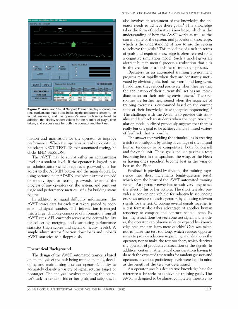
After a test, the AVST displays the results as shownin Fig. 7. This display shows the correct classificationsfor the test signals, the operator’s answers, and the op-erator’s new proficiency level. In addition, the operatorsees his or her number of plays, time taken, and historicalsuccess rate for each signal. To benchmark his perfor-mance, he also sees the most recent information onnumber of plays, time taken, and success rate for alloperators currently training with the AVST throughoutthe Fleet.
Before beginning another test, the operator can playand display any of the signals he missed (or correctlyidentified) to correct (or reinforce) his understandingof signal identification. Controls available to him in-clude PLAY and INFO, which operate as describedbefore. PLOT PROGRESS calls up a graph of his pro-ficiency level plotted against time. The graph alsoshows average levels for any squadrons, wings, or theFleet. The HIGH SCORES button lists operators withthe top scores. Feedback between tests provides infor-
NS HOPKINS APL TECHNICAL DIGEST, VOLUME 18, NUMBER 1 (1997)
EXTENDED ECHO RANGING AURAL AND VISUAL SUPPORT TRAINER
Figure 7. Aural and Visual Support Trainer display showing theresults of an automated test, including the operator’s answers, theactual answers, and the operator’s new proficiency level. Inaddition, the display shows values for the number of plays, timetaken, and success rate for both the operator and the Fleet.
mation and motivation for the operator to improveperformance. When the operator is ready to continue,he selects NEXT TEST. To exit automated testing, heclicks END SESSION.
The AVST may be run at either an administratorlevel or a student level. If the operator is logged in asan administrator (which requires a password), he hasaccess to the ADMIN button and the main display. Byusing options under ADMIN, the administrator can addor modify operator testing passwords, examine theprogress of any operators on the system, and print outusage and performance metrics useful for building statusreports.
In addition to signal difficulty information, theAVST stores data for each test taken, parsed by oper-ator and signal number. This information is mergedinto a larger database composed of information from allAVST sites. APL currently serves as the central facilityfor collecting, merging, and distributing performancestatistics (high scores and signal difficulty levels). Asimple administrator function downloads and uploadsAVST statistics to a floppy disk.
Theoretical BackgroundThe design of the AVST automated trainer is based
on an analysis of the task being trained, namely, devel-oping and maintaining a sensor operator’s ability toaccurately classify a variety of signal returns target ornontarget. The analysis involves modeling the opera-tor’s task in terms of his or her goals and subgoals. It
JOHNS HOPKINS APL TECHNICAL DIGEST, VOLUME 18, NUMBER 1 (1
also involves an assessment of the knowledge the op-erator needs to achieve these goals.4 This knowledgetakes the form of declarative knowledge, which is theunderstanding of how the AVST works as well as thecurrent state of the system, and procedural knowledge,which is the understanding of how to use the systemto achieve the goals.4 This modeling of a task in termsof goals and required knowledge is often referred to asa cognitive simulation model. Such a model gives anabstract human mental process a realization that aidsin the creation of a machine to train that process.
Operators in an automated training environmentprogress most rapidly when they are constantly moti-vated by obvious goals, both near-term and long-term.In addition, they respond positively when they see thatthe application of their current skill set has an imme-diate effect on their training environment.5 Their re-sponses are further heightened when the sequence oftraining exercises is customized based on the currentstate of their knowledge base (adaptive sequencing).5
The challenge with the AVST is to provide this stim-ulus and feedback to students when the cognitive sim-ulation model outlined previously suggests that there isreally but one goal to be achieved and a limited varietyof feedback that is possible.
The answer to providing the stimulus lies in creatinga rich set of subgoals by taking advantage of the naturalhuman tendency to be competitive, both for oneselfand for one’s unit. These goals include passing a test;becoming best in the squadron, the wing, or the Fleet;or having one’s squadron become best in the wing orbest in the Fleet.
Feedback is provided by dividing the training expe-rience into short increments (eight-question tests),which form the heart of the AVST automated trainingsystem. An operator never has to wait very long to seethe effect of his or her actions. The short test also pro-vides a convenient vehicle for adaptively sequencingexercises unique to each operator, by choosing relevantsignals for the test. Grouping several signals together ina test format also takes advantage of another humantendency to compare and contrast related items. Byforming associations between one test signal and anoth-er, the operator can observe rules to expand his knowl-edge base and can learn more quickly.5 Care was takennot to make the test too long, which reduces opportu-nities to provide adaptive sequencing and also bores theoperator, nor to make the test too short, which deprivesthe operator of productive association of the signals. Inaddition, certain mathematical considerations having todo with the expected test results for random guessers andoperators at various proficiency levels were kept in mindas the length of the test was determined.
An operator uses his declarative knowledge base forreference as he seeks to achieve his training goals. TheAVST is designed to be almost completely intuitive, so
997) 119

A. C. COON ET AL.
that little time is spent learning and remembering howto operate the trainer or interpret its displays. The stateof the system consists of variables the operator mayrapidly read from the screen, such as his current pro-ficiency level, his current screen display settings, andother parameters seen on the main, information, andtest displays. These representations are limited in scopeand focus on the information that is most pertinent totraining the specific signal identification skill.
An operator’s procedural knowledge base develops ashe or she proceeds with automated training. Funda-mental to the development of this knowledge base iswhat is known as a production memory, as well as a setof precepts known as production rules.6 As an operatorencounters signals during testing, he is continuallyobserving mappings of audiovisual experiences totarget/nontarget classifications. This experience entershis production memory. Production rules are really el-ementary “if-then” statements that are acted upon dur-ing testing based on the contents of the productionmemory.7 The operator’s procedural knowledge base, orknowledge of how to reach his goals, grows as he comesup with new production rules and solidifies old ones.These rules influence and improve his behavior, and arethe essential building blocks of his skill base. An ex-ample of a simple production rule might be the state-ment: “If the aural playback of a signal is a very shortclicking sound, then it is an electrical glitch.”
Production rules are developed more rapidly whenthe operator is in a goal-oriented environment. TheAVST system is designed to return the operator againand again to conditions under which he or she mustassimilate production rules, without making the processtedious. As the operator strives to achieve goals, suchas passing tests, raising his proficiency level, and beat-ing other operators, he unconsciously maximizes thenumber of signals he hears and sees. As the tests growmore challenging, he is driven to hunt for ever moreobscure production rules, primarily new clues for signalidentification, to boost his performance. He instinc-tively makes use of the full functionality of the AVSTto meet his goals. Intervention by the automated test-ing system is limited to the success or failure of theoperator’s past and present attempts to classify signalsto encourage operator experimentation and allow for adiversity of rule-forming styles.
AVST Hardware and Application Software
The original AVST package was hosted on a Sunworkstation. The Fleet, however, chose to rehost theAVST on a more mobile and affordable AMEWT PCavailable to the Fleet for training. The AMEWT is aNaval Air Systems Command-standardized IBM-com-patible PC. Its most common configuration includes a486/DX50 central processing unit, 8 Mbytes of random
120 JOH
access memory, a CD-ROM drive, and a 16-bit soundcard. It does not have an internal hard disk drive butinstead runs from a 150-Mbyte removable Bernoullicartridge. This allows it to remain an unclassified sys-tem, while the cartridge can hold classified informationseparately when not in use.
Before June 1996, the AMEWT was delivered strict-ly as a DOS-based system. Current system softwareBernoulli cartridges, however, include MS Windows3.1 as an available operating environment. For manyoperators, the opportunity to train with an operatingsystem they are already familiar with provides an im-mediate level of comfort. Previously, operators wereconfronted with a blur of different user interface styleson DOS-based trainers. Now they are much more ableto learn from the testing material, since they can accessit with a familiar graphical user interface that includesMicrosoft-standard buttons, menus, and list boxes.
As on any platform, software for the AMEWT mustbe developed within the constraints of its hardware andoperating system configuration. In addition, the devel-oper must consider standardized policy decisions re-garding operating procedures. For example, securityconcerns dictate that AMEWT users may not writedata to the Bernoulli cartridge. Therefore, the AVSTis designed so that the administrator-level functionmentioned earlier, which prints out parameters fromthe training database, writes only to the floppy diskdrive. The update function, which downloads theautomated testing database and uploads Fleet-wide op-erator and signal statistics, involves the copying of filesfrom a floppy disk to the cartridge. This process iscontrolled directly by the AVST software to preventusers from writing to the cartridge on their own.
To a large degree, the success of the AMEWT-basedAVST in meeting sponsor requirements in a timelymanner is attributable to the use of Borland’s Delphi,a visual development tool that allows rapid prototypingand interface development. Unlike most other visualdevelopment tools, it is also a compiler that turnssource code into stand-alone executable code. Theoriginal Sun-based AVST is coded in Precision VisualsPV-Wave, an interactive data analysis/interface devel-opment tool. Borland’s Delphi was chosen over directtranslation of PV-Wave code from the Sun to the PCfor two main reasons: (1) PV-Wave requires a licensingfee for each target platform that is significant relativeto the cost of the PC, and (2) run-time interpreterssuch as PV-Wave require more work for the computer,a performance burden that is largely unnoticed on theSun but not on a midrange PC.
Typically, the downside to developing a stand-aloneexecutable code is the increased development timeinvolved with using a compiler. This added turnaroundtime is a particular problem for a small, relatively in-formal software project like the AVST, where the spon-
NS HOPKINS APL TECHNICAL DIGEST, VOLUME 18, NUMBER 1 (1997)

EXTENDED ECHO RANGING AURAL AND VISUAL SUPPORT TRAINER
sor and users may be expected to make numerous re-quests for changes in functionality or performance overthe course of the development cycle. The immediateresponse to a customer’s needs has a lot to do with thepopularity of the AVST and sponsor willingness to fundfuture development work at APL.
The ability to make rapid changes to the AVST soft-ware interface is a direct result of using “visual” develop-ment tools. Such development environments (e.g., VisualBASIC, PowerBuilder, Delphi) allow the developer tothink first and foremost in terms of the user’s interface.Much attention has been given to the concept of “object-oriented” software design and languages (C++, Ada, andSmalltalk, for example), and with good reason. The holygrail of code reuse appears within reach of the object-oriented paradigm. Too often, however, the promise ofmassive productivity gains from object-oriented designmethods has been difficult to fulfill. Part of the problemmay be that, although code may be organized in intuitive,object-oriented blocks, it is still code, and as such muststill too often be read and understood by anyone wantingto effectively use or reuse it.
The new visual tools advance the object-orientedparadigm by focusing the programmer’s attention onthe visual results of the code as it appears in the fin-ished product. Applications are component orientedand are built from large multiobject components(themselves objects) that already contain significantfunctionality on their own. Most important, these com-ponents are connected to the application with a min-imum of code. The programmer can literally “drag anddrop” a component object from a palette of optionsonto his or her application window. The code requiredimmediately follows it, with no further action neededexcept to add responses to component events. Findingthe code that activates when a virtual button on thescreen is clicked is as simple as clicking on the buttonin the design form and selecting OnButtonDown fromthe menu of events relating to that button component.
What might seem like a mere coding conveniencehas, in fact, resulted in massive gains in developmentspeed and programmer productivity. Thanks to thismarriage of object-oriented component technology anda visual perspective to software development, APL hasbeen able to develop a better trainer for the Fleet thatis more usable, maintainable, and modifiable than theyhad previously thought possible.
PATROL AVIATION EER TRAININGEach of the 15 patrol aviation (VP) squadrons in the
Navy continually form and reform flight crews aspersonnel receive orders into and out of a squadron.The squadron always attempts to maintain 12 combat-ready flight crews. Each squadron conducts extensiveongoing personnel training to keep combat readiness
JOHNS HOPKINS APL TECHNICAL DIGEST, VOLUME 18, NUMBER 1 (1
as high as possible. Figure 8 illustrates the administra-tive organization of the VP community. Active-dutyVP squadrons are organized into four patrol wings: twoin the Atlantic Fleet (Wing 5 and Wing 11) and twoin the Pacific Fleet (Wing 2 and Wing 10).
At the squadron level, specific flight crew trainingrequirements of all types of naval aircraft are promulgat-ed in a set of aircraft type-specific training “matrices.”The P-3C training matrix is jointly created by thecommanders of the naval air forces of both the Pacificand Atlantic Fleets. From the P-3C training matrix, aVP qualification exercise manual is jointly generated bythe commanders of the Pacific and Atlantic PatrolWings. The purpose of the manual is to provide eachsquadron with the description, requirements, proce-dures, and evaluation responsibilities for each trainingevent specified in the P-3C training matrix. The latestrevision of the VP qualification manual includestraining events for flight crews to become qualified andmaintain currency in the use of the EER system. As partof the EER training requirements, acoustic sensoroperators must complete 12 hours of aural and visualtraining using the AVST. Because of its portability andrelatively low cost, every active-duty patrol squadron hasan AMEWT capable of running the AVST application.
Fleet Replacement SquadronFigure 8 shows that VP-30 is not in the administra-
tive chain of command of any particular patrol wingbut, rather, is under the direction of the commander ofthe Atlantic Patrol Wings. (Although not indicated,the commander of the Pacific Patrol Wings providessome direction to VP-30 as well.) The squadron islocated at Naval Air Station, Jacksonville, Florida, andis the Fleet Replacement Squadron (FRS) for the entireVP community. The FRS provides initial training toofficers and enlisted personnel and develops a trainingsyllabus to prepare personnel for the aircrew trainingrequirements they must complete when they get totheir squadrons. The FRS maintains liaison with thetraining divisions of the patrol wings to recommendrevisions to the aircrew training syllabus and to obtainfeedback from operational squadrons should FRS train-ing fail to meet their requirements. It is the responsibilityof the operational squadrons to continue the trainingthat personnel received from the FRS to maximize theiroperational readiness.
For enlisted personnel designated as aviation warfaresystems operators (AWs) who are heading to the Fleetfor the first time (designated as Category I individuals),VP-30 provides a 9-month syllabus to qualify them asobservers in the aircraft. These junior AWs are intro-duced to the “single advanced signal processor” and re-lated equipment used by the P-3C for EER. VP-30 alsoprovides training to smaller groups of AW personnel who
997) 121

A. C. COON ET AL.
are either returning to a patrol squadron for their sec-ond sea tour (Category 2) or are qualified to fly onlyin older versions of P-3 aircraft (Category 3). For bothof these categories of AWs, VP-30 provides a more ab-breviated period of customized training to prepare themfor the Fleet. In all cases, an AW must complete therequired personnel qualifications standards syllabus in asquadron to become a qualified acoustic sensor operatorin the aircraft. All pilots, naval flight officers, and AWstudents receive an introductory schoolhouse lecture onEER. Currently, only the more experienced Category 2naval flight officers and AW students receive EERground school training consisting of more extensiveclassroom lectures and weapon systems trainer periods.
Tactical Support CentersAll of the commands shown in Fig. 2 are adminis-
trative as well as operational. As a result, many of thepersonnel in these commands have dual roles. Support-ing the assigned missions of the VP squadrons is anorganization of tactical support centers (TSCs). For alloperationally tasked antisubmarine warfare missions, aTSC provides the flight crew with an extensivepreflight brief. This preflight brief covers most aspectsof the mission, including, for example, ocean andatmospheric environmental predictions, intelligence
time analysis systifications to the include automatAVST will be in
The 14B53A PThe 14B53A
provide EER traitrainer since it is aircrew: the acoucoordinator (TACrole in training coators and the TAconsoles and switfor crews to learn14B53As in the Nof this trainer, thtrainer for the EEmode, the 14B5actual, recorded dtors with any falduring actual EERgraphic model intopography and h
To overcome tthe Navy contra
Figure 8. Administrative command structure of the patrol aviation (VP) community.Squadron training requirements are generated by COMPATWINGSPAC/LANT but pro-mulgated by joint instruction from COMNAVAIRPAC/LANT.
Chief of Naval Operations
VP 4
VP 9
VP 47
VP 1
VP 46
VP 40
COMPATWING 10COMPATWING 2 COMPATWING 5 COMPATWING 11VP 30
VP 8
VP 11
VP 10
VP 5
VP 45
VP 16
VP 26
Commander in ChiefPacific Fleet
COMPATWINGSPAC
COMNAVAIRPAC
Commander in ChiefAtlantic Fleet
COMNAVAIRLANT
COMPATWINGSLANT
122 JOH
on the target of intent, and acousticsearch tactics. After a mission theTSC debriefs the aircrew, and alllogs and data tapes are collectedand reviewed. The relevant intelli-gence and tactical data collectedfrom the flight are then enteredinto the TSC’s database and dis-persed to other agencies with a needto know.
Besides being a repository ofinformation collected by all flightcrews, the TSC also helps trainflight crews. This is done in twoways. First, for most operationalmissions, TSC personnel performan evaluation of the flight crewbased on analysis of the returnedflight data. Second, the TSC pro-vides training aids. Under directionfrom the Naval Command, Con-trol, and Ocean Surveillance Cen-ter In-Service Engineering EastCoast Detachment, APL isintegrating AVST software into allTSC mission support systems. Spe-cifically, all TSCs carry Sun systemsas part of their acoustic processingconfiguration, referred to as a fast-
em, that can host the AVST. (Mod-Sun-based AVST are being made toed testing.) Once integrated, thestalled at TSCs worldwide.
art-Task Traineris a part-task trainer designed to
ning. It is referred to as a part-taskdedicated to training only part of thestic sensor operators and the tacticalCO). The 14B53A plays a valuableordination between the sensor oper-
CCO. In addition, its realistic displayches provide a favorable environment EER controls. There are only threeavy. Besides the limited availability
e 14B53A has other drawbacks as aR system. When used in a stand-alone3A produces synthetic, rather thanata and does not present the opera-
se contacts, which occur frequently missions. In addition, the oceano-
the 14B53A assumes a flat-bottomomogeneous water mass.
he drawbacks of using synthetic data,cted for a single EER basic training
NS HOPKINS APL TECHNICAL DIGEST, VOLUME 18, NUMBER 1 (1997)
EXTENDED ECHO RANGING AURAL AND VISUAL SUPPORT TRAINER
exercise, emphasizing EER processing functionality,in a deployable acoustic readiness trainer system(DARTS) format. The DARTS EER lesson uses a roll-on/roll-off tape drive unit that provides acoustic train-ing on a parked aircraft or in the 14B53A trainer. TheDARTS uses recorded EER data samples that are inputto the acoustic processing gear. The DARTS EER les-son has been lauded as the best source for basic EERtheory and operations. Unfortunately, the DARTSprogram is currently unfunded, and, without furtherEER lessons, the training value of this single lesson isgreatly diminished after an operator’s first or secondexposure.
SUMMARY AND FUTURE WORKThe AVST is a success for three reasons: it is simple,
challenging, and fun. Navy operators are often over-whelmed by computer systems. The easy-to-use AVSTinterface shortens the operator’s learning curve and letshim or her focus immediately on training. As a skill-based trainer, the AVST requires little coursework orprior knowledge to use. The design breeds healthycompetition against the machine and among operators,which adds to the challenge and enjoyment of thesystem by a generation of users immersed in an era ofvideo games.
Future work at APL will extend the scope of theAVST to include more of the sensor operator’s
JOHNS HOPKINS APL TECHNICAL DIGEST, VOLUME 18, NUMBER 1 (1
processor functions beyond that of aural and visualclassification. This will allow limited 14B53A or in-flight training sessions to be more productive. In ad-dition, APL is leveraging the software to developdesktop trainers for follow-on air antisubmarine war-fare systems.
REFERENCES1 Tyler, G. D., “The Emergence of Low-Frequency Active Acoustics as a
Critical Antisubmarine Warfare Technology,” Johns Hopkins APL Tech. Dig.13(1), 145–159 (1992).
2 Savage, J. E., Basic Introduction to Air ASW Acoustic Systems, NADC-91109-50,Naval Air Development Center, Warminster, PA, pp. 101–121 (Jan 1992).
3 Shin, F. B., Kil, D. H., and Wayland, R., “IER Clutter Reduction in ShallowWater,” in Proc. IEEE Int. Conf. on Acoustics, Speech, & Signal Processing,Vol. 6, pp. 3041–3045 (1996).
4 Kieras, D. E., The Role of Cognitive Simulation Models in the Development ofAdvanced Training and Testing Systems, Univ. of Michigan Tech. Rep. no. 23,p. 2 (1987).
5 Williams, K. E., An Evaluation of a Methodology for Cognitively Structuring andAdaptively Sequencing Exercise Content for Embedded Training, Univ. of CentralFlorida Tech. Rep. no. 89-035, pp. 13–18. (1990).
6 Kieras, D. E., “An Approach to the Formal Analysis of User Complexity,” Int.J. Man-Mach. Stud. 22, 365–389 (1985).
7 Williams, K. E., “The Acquisition of Cognitive Simulation Models—AKnowledge Based Training Approach,” in Knowledge-Based Simulation: Meth-odology and Application, P. A. Fishwick and R. B. Modjeski (eds.), Springer-Verlag, New York (1990).
ACKNOWLEDGMENTS: We express appreciation for the continuedsupport from PMA-264 and PMA-205, along with NAWCAD, supporting con-tractors, and Fleet personnel. In particular, we wish to thank Captain StanleyDouglass, AWCS David DeVarney, Nicholas Gallipoli, AWC Scott Register,Raymond Roth, Richard Hollis, Kenneth Sola, Linda Reed, Gary Lewis, and AW2Edward Rainey for their help and all patrol aviation training personnel whosededication enable development of the AVST.
THE AUTHORS
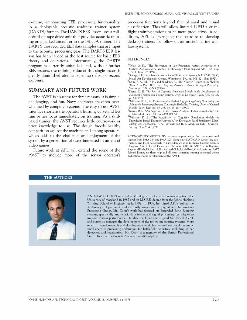
ANDREW C. COON received a B.S. degree in electrical engineering from theUniversity of Maryland in 1987 and an M.S.E.E. degree from the Johns HopkinsWhiting School of Engineering in 1992. In 1988, he joined APL’s SubmarineTechnology Department and currently works in the Signal and InformationProcessing Group. Mr. Coon’s work has focused on Extended Echo Rangingsystems, specifically, multistatic data fusion and signal processing techniques toimprove system performance. He also developed the original Sun-based AVSTand currently manages the development of the follow-on training systems. Morerecent internal research and development work has focused on development ofsmall-aperture processing techniques for battlefield acoustics, including sniperdetection and localization. Mr. Coon is a member of the Senior ProfessionalStaff. His e-mail address is [email protected].
997) 123

A. C. COON ET AL.
124 JOHNS HOPKINS APL TECHNICAL DIGEST, VOLUME 18, NUMBER 1 (1997)
PETER C. GALLATI is a Senior Professional Staff mathematician in APL’sSubmarine Technology Department. He obtained a B.S. degree in mathematicsfrom the U.S. Naval Academy in 1978 and an M.S. degree in computer sciencefrom The Johns Hopkins University in 1990. Mr. Gallati served in the U.S. Navyas a Naval Flight Officer in Patrol Squadron 16 from 1980 to 1983, where hequalified as a Patrol Plane Tactical Coordinator and Mission Commander. He wasassigned to the Navy Regional Data Automation Center from 1983 to 1986, wherehe served as a computer programmer/analyst on a wargaming project for the JointChiefs of Staff. Since coming to APL in 1986, he has supported a variety ofprojects and at-sea tests primarily for the Submarine Technology Department, andhas logged over 500 hours of special crew time, primarily flying ASW missions, invarious types of P-3 aircraft. He is currently engaged in developing methods tomeasure and improve military aircrew performance and proficiency. His interestsinclude design and development of methods to quantify and improve team trainingand support bioinformatics initiatives for the Submarine Technology Department.His e-mail address is [email protected].
CHRISTOPHER A. ROSS received an A.B. degree in chemistry from PrincetonUniversity in 1985 and an M.S.E. degree in electrical engineering from theCatholic University of America in 1996. From 1986 to 1989, he was a spacecraftanalyst with Bendix Field Engineering Corp. and a member of a real-time sciencesatellite operations crew. From 1989 to 1996, he was a programmer andapplications software engineer with SFA, Inc., first at the Naval ResearchLaboratory (NRL) and then at APL. At NRL, he developed interactive three-dimensional data visualization packages and GUIs on Silicon Graphics Irisworkstations in support of research in ocean acoustics. At APL, he developedsoftware and performed analysis work in the Signal and Information ProcessingGroup of the Submarine Technology Department. He archived signals to buildthe AVST signal database and developed design specifications for the automatedtraining feature that was added to the original Sun-based AVST. Mr. Ross is amember of the Associate Professional Staff. His e-mail address is [email protected].
ROBERT W. CHALMERS is a scientific analyst working for SFA, Inc., in APL’sSubmarine Technology Department. He received a B.S.E.E. degree from FloridaState University in 1986 and an M.S. degree in applied physics from The JohnsHopkins University in 1994. Mr. Chalmers was responsible for the design,development, and coding of the AMEWT AVST software. From 1986 to 1992he was employed as an Electrical Design Engineer at Westinghouse OceanicDivision, developing software and digital circuitry for a variety of Navy sensorsystems. He has since worked for APL performing ASW data analysis anddeveloping analysis, simulation, and training software tools for APL and Navyuse. His software specialties include multimedia, artificial intelligence, and real-time programming. His e-mail address is [email protected].


