
the Existing Campus Building foccesinbillty.
97
s. DOCUMENT RESUME. ED 251981 - EA .017 396 * AUTHOR Cotler, Stephen Richard TITLE Construction Guidelines and Specifications. Modifying the Existing Campus Building foccesinbillty. INSTITUTION American Council on Education, Washington, D.C.; Association of Physical Plant Administrators of Universities and Colleges, Washingtnn, D.C. SPONS AGENCY, Department df Educhtion, Washington, DC. PUB DATE 81 CONTRACT 300-79-0797 NOTE 103p. PUB TYPEe .* Guides - Non-Clasirbom Use (055) EDRS PRICE MFO1 /PC05 Plus Postage.. DESCRIPTORS , *Accessibility (for Disabled); Campus Planning; *Design Requirements; *Educational tacilities Design; *Educational Facilities Improvement; Federal Legislation;, HiiheeEducation; Physica1-10bility; ' *Structural Elements (Construction) IDENTIFIERS Architectural Barriers Act 1968; Rehabilitation Act 1973 (Section 504) : 'ABSTRACT To ,address- problems that the campus faces when attempting to make facility modifications that meet federal handicap accessibility requirements, this guidebook gives guidance on requirements and methods of "retrofitting" that meet the mobility needs of the disabled. Seven chapters discuss modifications to site, entrance, doors, inferior circulation, restrooms, drinking fountains, and special spaces.. Each chapter is further divided into three sections. The first section uses a mandatory evaluation requirements checklist, drawings, and text to aidin evaluation of existing facilities to see if they provide accessibility for the dis'abled. The second section presents architectural construction drawings as solutions to common problems found in existing facilities. The Arawings can also be used in new construction. The third section includes architectural specifications. An appendix, discusses useful tools and procedures for the facitity survey. (DCS) tit ft. . ft*************************************************************#v****** * Reproductions supplied by EDRS are the best that can be made * * from the original document. * .,***********************************************************************
Transcript of the Existing Campus Building foccesinbillty.

s.
DOCUMENT RESUME.
ED 251981 - EA .017 396*
AUTHOR Cotler, Stephen RichardTITLE Construction Guidelines and Specifications. Modifying
the Existing Campus Building foccesinbillty.INSTITUTION American Council on Education, Washington, D.C.;
Association of Physical Plant Administrators ofUniversities and Colleges, Washingtnn, D.C.
SPONS AGENCY, Department df Educhtion, Washington, DC.PUB DATE 81CONTRACT 300-79-0797NOTE 103p.PUB TYPEe .* Guides - Non-Clasirbom Use (055)
EDRS PRICE MFO1 /PC05 Plus Postage..DESCRIPTORS , *Accessibility (for Disabled); Campus Planning;
*Design Requirements; *Educational tacilities Design;*Educational Facilities Improvement; FederalLegislation;, HiiheeEducation; Physica1-10bility; '*Structural Elements (Construction)
IDENTIFIERS Architectural Barriers Act 1968; Rehabilitation Act1973 (Section 504) :
'ABSTRACTTo ,address- problems that the campus faces when
attempting to make facility modifications that meet federal handicapaccessibility requirements, this guidebook gives guidance onrequirements and methods of "retrofitting" that meet the mobilityneeds of the disabled. Seven chapters discuss modifications to site,entrance, doors, inferior circulation, restrooms, drinking fountains,and special spaces.. Each chapter is further divided into threesections. The first section uses a mandatory evaluation requirementschecklist, drawings, and text to aidin evaluation of existingfacilities to see if they provide accessibility for the dis'abled. Thesecond section presents architectural construction drawings assolutions to common problems found in existing facilities. TheArawings can also be used in new construction. The third sectionincludes architectural specifications. An appendix, discusses usefultools and procedures for the facitity survey. (DCS)
tit
ft.
.
ft*************************************************************#v******* Reproductions supplied by EDRS are the best that can be made *
* from the original document. *
.,***********************************************************************

:.';,7,1W(ft.e 1.! o!...pvgft:15,-.*Nv .r.ots) ." .,.
e't . .:
ip`the.Eadgting campus. BuildingforAccessibilfty.
on Guidelines ahcI
by Stephen Richard Coder, Architect
S
a
4 4
ci
a
.1
a.
40
4,
a-
a
f. 54
The Assoolailon of. Physical Pk** Administrators of lit,,Iversitles and Colleges
.
U.S. DEPARTMENT OP EDUCATION *:i.
NATIONAL INSTITUTE OF EDUCATION . b
I Di ICA III At RI SOURCES INFORMATION(-T
....
N I T R (TRIO
KIN,.ument tuts hoer, reproduced at ,;
ft. r.yort f tom Int. petsun or .otganstatron :
nn..o...erIng it :!
Wu It i Kemp.. hay.. bee macre to improve,, Ivo 141/4. 11.itt ilti.ihtV
. i
P..ottl . if ww or op...mons stated in this docuflood du not net In.s.tni tegument olltreal ARE 1pos41011 I It P0131 V
S.
I.
*
4
a..

4.0
V
.
V
-Modifying thebExisting Campus Building\
A. for Accessibility:
Construction Guidelines andSPeCifiCatkiwil. t
by Stephen Richard Cotler, Architect
4is
I
The Association of Physical Plant Administratorsof Universities and Colleges
.1
Originally produced for the Deparbnent of Education
4
V

4,
40
4
yac.'64111'
0
1 40
Copyright © 1981 by the Association of lhysical PlantAdministrators of Universities and CollegeEle lion Dupont Circle, Suite 250Washington, D.C. 20036
Library of Congress Catalog Number: 81-65326.
This publication was prepared as an account of worksponsored by the AssodatiOn of Physical Plant Adminis-trator's of Universities and Colleges (APPA) Eleven Du-pont Circle, Suite 250, Washington, D.C. 20036.
This project has been funded in part with Federal fundsfrom the Department of Education (ED) under contract#300-79-0797 with the American Council on Education(ACE). The contents of this publication do not necessarilyreflect the views or policies of ED or ACE, nor doesmention of trade names, commercial products or organi-zations imply endorsement by the'U.S. government.
No APPA employee, member, condu:tant or authorwhose work is contained herein makes any warranty,express or. implied, or assumes any legal liability or re-sponsibility for the Vattin', completeness Or usefulnessof any information, apparatus, product or process dis-closed, or3presents that its use would not infringe upon'privately owned rights.
Printed in the United States of Anierica.
a
4

Preace
-Mandates for AccessibilitySeveral federal and many state laws and codes re-qiiire that buildings be accessible to the physicallyhandicapped. The passage of the Rehabilitation Actof 1973 (Public Law 93-112) broadened the coverageof accessibility requirements affecting higher edu-
. cation. Section 504 of this Act states: "No otherwisequalified handicapped individual in the UnitedStates . . . shall, solely by reason of handicap, beexcluded from participation in, be denied the bene-
. fits of; or be subjected to discrimination under anyprogram or activity receiving Federal financial assis-tance."
HEW's regulations implementing Sectidi; 504 be-cameeffective on Jung 3, 1977, and require recipi-ents of HEW fynds to make all programs andservices accessible to qualified handicapped indi-viduals.. To accomplish this, retrofit of existingbuildings may .be necessary. This publication ad-dresses those problems that the campus faces whenattempting to make these modifications. It has beenfound that man retrofits" for accessibility do notmake the buildings truly accessible, because thedesigner did not fully understand the needs of thedisabled. Modifications such as curb cuts, whichhave been constructed using too steep an angle andan abrupt edge at the street level, can actually bemore dangerous to the disabled person than nocurb cuts at all. This publication will help you createan affordable accessible environment by givingguidance on requirements and methods of retrofit-ting that meet the needs of the disabled.
An Overview of Section SO4and Other LawsStructural modifications do not have to be madvitonevery campus building. They do have to be madewhere programs are offered. The concept of pro-gram accessibility, a key term in Section 504,ensures that all federally assisted programs and ac-
tivities, when viewed on their entirety, are accessi-blk to handicapped peoofts. Program. accessibilitydoes not require that all existing facilities be madeaccessible, so long as the programs and activities, asa whole, are accessible: Thus a college or universitymay provide for full participation for haddicappedstudents, staff, and faculty without :renovating,every existing classroom building, office space, orresidence hall. This requirement, for program ratherthanlatility accessibility may relieve some schoolsfrom the necessity of extensively ienovafing bite-hues. If, however', a building houses programs oractivities not available elsewhere, 9r serves a cere-monial-ertraditional fundtioii that caii be consid-ered part of the institution's program', then physicalaccess for -handicapped individuals may be re.quired.
In addition, the regulation requires that any altera-dons made to a facility omen of a facility that couldaffect the usability of the building must "to themaximum extent feasible" make the altered facilityor portion of the facility accessible to and usable byhandicapped persons. For example, if a doorway orwall is being altered, the door or' new wall openingmust provide the necessary clearance to accommo-date people in wheelchairs. It on the other hand,the roof were being replaced, there would be norequirement for accessibility features since the alte-rations cannot be done in a way that would affectaccessibility of the building. This requirement,which applies 'to any alterations undertaken afterJune 3, 1977, could affect a significant number ofcampus buildings as older structures are systemati-cally rehabilitated.
Presidential Executive Order 11914 of 1976 concern-ing Section 504 mandated all federal agencies thatextend financial assistancelO recipients to develop,publish, and implement Section 504 regulations.Further, it directed the Department of Health, Edu-catioh, and Welfare (HEW) to develop guidelinesfor agency review to ensure the consistency of theseregulations.

IV
Executive Order 11914 was superseded onNovember 2,191#0 by Executive Order 12250 whichconsolidated all dvil rights coordinating authorityin the Department of justice. The impact on Section504 is significant because the Department of Healthand Human Services (successor to HEW) no longerhas the responsibility foir coordinating the de-velopment of the kegulafions. This new ExecutiveOrder expands the responsibility to include coor-dinating the implementation of the regulations andtechnical assistance and training. If an institution isreceiving ftinding from several federal agencies, itshould contact the Office of Coordination and Re-view within the Department of Justice to resolveany inconsistencies of overlapping Section 504 reg-ulations. . .
Another federal law t hat might have applicabilityon campuses is the Mchitectural Barriers Act of1468, which requires.that all buildings and facilities
. owned, occupied, or financed by the United Statesgovernment be accessible to and usable by handi-capped persons. Specifically, this law applies tobuildings and facilities designed, constructed, al-tered, or leased by the federal government afterAugust 12, 1968, and to those whose construction
` was financed wholly or in part with federal funds.__Responsibility for establishing accessibility stan-
dards for all Such buildingsand facilities is assignedto the Administrator of General Services, theUnited States Postal Service, and e Secretaries ofthe Departments of Housing and rban Develop-ment and Defense, in consultatio with the Secre'tary of Health, Education and Welfare. Enforce-ment of compliance rests with the federal agenciesand the Architectural and Transportation BarriersCompliance Board.
This act would apply to construction fundedthwtigh federal programs such as the Higher Edu-colon Facilities Act and the College Housing LoanProgram.. In September 1969, the General ServicesAdministration and several federal agenciesadopted ANS: A117.1 as the standard for com-pliance. Therefore, most facilities constructed sinceSeptember 1999. ith federal su port must complywith ANSI A117.1 (1961, R 1971).
In January 1.981 the Architectural and Transporta-tion Barriers Compliance Board (ATBCB) adopted anew minimum accessibility guideline. The Ar-:chitectural Barriers Act implies that the fourstandard - setting agencies previously mentionedmust conform to ATBCB's minimum guideline. Theconsequence of this implication is that if your cam-pus receives federal construction money, you will
be under the regulations of one or more of thestandards set by the standard-setting agencies. Ifyour campus is using anyAfederal monies for con-struction, you should stay abreast of any regulatoryaction taken on this subject. You should-also studythe intricacies of the Architectural Barriers Act.
It is poisibie that a particular facility on your cam-pus is subject to compliance under both Section 504and the Architectural Barriers Act. For example, aninspector for Section 504 compliance could.review afacility on your campus and recommend that. youspend .$15,000 to modify the building to meet 504requirements, mak)ing both architectural and pro-gram modifications. Then after the.. retrofit wascompleted, an inspector from ATBCB could findthat the building was not built to agency standardsestablished by the Architectural Barriers Act. Itmight cost your campus approximately $100,000 ,toretrofit this facility to meet the Act's requirements.Again, it Should be emphasized that it is the campusadministrator's responsibility. to !understand thepossible overlap of these laws because the differentenforcement agencies might or might not be awareof other federal jurisdicticn. 'In addition, many states and local jurisdictions havesome type, of law on the books regarding architec-tural barriers. Most of these laws preceded passageof federal legislation. Thi coverage of these lawsvaries greatly. Some legislation covers only state-owned or state-funded new construction; some re-quires accessibility, features to be included in anymajor alterations for such projects; and still otherscall for accessibility in all publicly used buildings,such as theaters, restaurants, hotels, muldfaniifyresidential units, and similar commercial, indus-trial, or health installations.
Standards and CodeiFederal, state, and local accessibility requirementsare implemented through the application of designspecifications or standards, generally enforced bymeans of building codes. The American NationalStandards Institute (ANSI A117.1), "Specificationsfor Making Buildings and Facilities Accessible to,and Usable by, the Physically Handicapped," is theoriginal, and still most widely used, accessibilitystandard. First issued in 1961 and reissued withoutchange in 1971, the original edition is officially des-ignated as ANSI A117,1-1961 (R 1971)..An extensiveresearch project, conducted from 1974 to 1979, hasculminated in a revised and expanded document,ANSI A117:1(1980).

40'
e
ANSI standards do not have the force of ltyv. Theyare, rather, a recommended set of minimum designcriteria established to serve as the basis for codes*and regulatioas. The purpose of ANSI A117.1 is to
0 spedf a uniform set of minimum requirementsbelow whicVshe detailed requirements of codesand regulati %thould not fall.
A standard his the force of laW only when it isspecifically referenced in a building code, regula-tion, or legislative act. Following its, issuance in1961, ANSI A117.1 was adopted in many of thebuilding ;odes, regulations, and state accessibilitylaws. It . has also been adopted by many federalagencies: it is the standard for design of newfacilities and alterations referenced in HEW's Sec-tion 504 regulations. Wherever ANSI A117.1-1961(R 1971) is referencedas (t is in HEW's regulation'the 1980 revision will not apply unless an until
>"
.
each regulation, code, or statute is amen ded to in-clude it.
If there are seveital applicable 'requirements, com-pliance with thistricter code, where a differenceexists, usually ensures compliance with the lessstringent requirement. in addition, most state and 0
local codes, as well as HEW's regulationek for im-plementing Section 504, provide for approval in thereferenced standard, if equivalent or better access isprovided by the alternate means.
Although many building codes are based on one ofthree major codes and most accessibility require-ments follow ANSI A117.1-1961 (R 1971)trelativelyclosely, it is impossible to generalize about loCatcode requirements. Most codes differ, if not In de-sign specifications, then in scope and coverage of ,tfie accessibility requirements.
O
a
4
a

l.
a
Table ofContents
Preface
Acknowledgments6 Introductkin
Chipter 1 SITEA Fath of Travel
.... Curb Cuts .
Parking SpacesGratings ..
Construction, Drawings
Chapter 2 ENTRANCESelection of the Accessible
EntranceRamp Changes of LevelStairs.Construction DrawingsConstruction Specifications
Chapter 3 DOORS 21
. Doors: Exterior and InteriorPower OperatorsPower Operation of
Existing DoorsAccessible ThresholdsDoor HandlesL,,ors Leading to
Dangerous AreasConstruction Drawings
. Construction Specifications
Chapter 4 INTERIOR CIRCULATIONHorizontal Circulation and
Spaces Needed for ProgramAccessibility
StairsEdges of Dangerous Low AreasProtruding Objects in
Path of TravelVertical Circulationthe
ElevatorWheelchair LiftsConstruction DrawingsConstruction Specifications
for Elevators
O
431
P

I.
.1b
Chapter 5 RESTROOMS e .
Entranceway. and RestroomFloor Layout
Toilet StallsShowersBathtubriLavatories and Restroom
AccessoriesAttaching Grab BarsLavatory Selection and CriteriaConstruction Dr= wingsConstruction S cations
Chapter 6 DRINKING F UNTAINS .63Drinking FollintainsConstruction DrawingsConstruction Specifications
39
Chapter 7 SPECIAL SPACESAreas of AsseMblyDormitory and Kitchen
SpacesDining Halls and
CafeteriasLibrariesPhysical Education
FacilitiesLaboratoriesSignageConstruction DrawingsConstruction Specifications
Appendix
, Useful Tools for Survey
67
87

Acknowledgments
Advisory and Review CommitteeBurr C. Folts, ChairmanAssistant Vice President for Physical FacilitieiState University of New York at Buffalo
Gaetano P. RussoAssistant Vice Chancellor for Facilities
ManagementUniversity of California/Bsrkeley
Rudolph TichyDirector of FacilitiesUniversity. of Wisconsin/Milwaukee
Author/Principal Researcher
tsigo
Rudy Frank ..
. Aging Division Director for External TechnicalAssiseance.Division
Department of Education, Officv for Chill Rights
Martha Redden .HEATH Project Admiristrator,
Richard RoweDirector, Division for. Eligibility and Agency
EvaluationDepartment of Education; Office for Civil Rig is
The people and organizations :Wed above offeredtheir experience and solutions to help make thispublication I _would like to express my
S
Stephen Richard Coder; ArchitectAccessible Design Consultants
Project Management StaffProject Manager:Paul T. Knapp, CAEAPPA Executive Director
Editor:Barbara J. FatkinDirector of PublicationsAPPA .
Special appreciation is extendedto the following people:Jim BennettBranch Chief for Technical Assistance
DevelopmentHealth and Human Services, Office for Civil
Rights
possible.appreciation to the architects of the New York StateUniversity Construction- Fund program who madethe 32 state:operated campuses of the universitysystem accessible to the disabled. The broad scopeof problems and design solutions gained throughthis program enabled me to combine some of thealternatives used in this publication. Special thanksto the architectural firm of Levatich and Hoffmanfor the closet details shown in "Typical Sleep/StudyRoom 'A' (page 75).
I would like to mention Nshard Anderson andMaggie Coons, both formerly with APPA, withoutwhose support thii project would not have been areality.
Thanks is also due my longtime friend RonaldMace, MA, of Barrier Free Environments, Inc.,North Carolina, for the use of several graphics hehas developed over the years. Also to be acknowl-edged are the members of Accessible Design Con-sultants who worked many long hours on thisproject.Ed Drake
Equal Opportunity SpecialistDepartment of Education, Office for Civil Riglits
10
Stephen R. Cotter
.
I X

kroduction
This publication is divided into seven chapters,each of which is further divided into three sections.The section divisions for each chapter are explainedbelow: _.
Section AlEvaluatiniriteria: With' wings text,and checklists, existing facilities can evaluated tosee if they provide accessibility for bled indi-viduals. Section A . provides infrma on enablingthe user to investigate an existing Ca buildingand to determine whether a person wi rdisabilitycan enter and use the interior spaced uited forSection 50epr9gram accessibility. It ust be em-phasized that The teria contained in first sec-tion, if followed, o not provide a. free envi-ronment, but that those items e = ntial forbasic accessibili are met. The en used forevaluating existing buil4jngs are not meant to be used foreither the modification of edsting facilities oil for newconstruction but solely to measure the editing Wilding todetermine if it meets the basis needs of disabled irslimdu-
. .
Mandatory evaluation requirements are outlined inchecklist form (0) at the beginning ofthe section.Other information is phown for a better overview ofthe problenufencountered when modifying a build-ing.
If an existing facility on your campus does not meetthe Section A evaluating criteria, you can correct theproblem by using the drawings (Section B) andspecifications (Section C) found 4n each chapter.
It
Section 8/Solutions: Architectural construction draw- %,kip ate presented in Section B as solutions to coin; AImon problems typically found in kisting facilities.These solutions meet the new ANSI A117.1 1980Standard as well as many other standards found ..
across the country. It is emphasized that afore theedrawings are used, they shauld be reviewed by an ar-chiteet to assure compliance with bail environmentalconditiqns and building codes. Althinigh these draw-ings hive been created for modification, they canalso be used for depils in new construction.,
Section CISolutions: Thine areas requiring written.specificatiOns are induded in Section C, Architec-tural Spedficatioifications can bework. They, too,sional for
As with the ciniwings, the spec-for both new and modification
id be reviewed by a licensed profes-II I',
CostsCosts play' an itnportant part in complying withSection 504. Because of the detailed informationand the years of experience required for someone tomake an accurate cost projection of constructionwork, we are licit attempting to provide 'cost infoi-ination. This book is published and intended to beused along with Modifying the Existing Campus Build-ing for Accessibility: Accfssibk Products Catalog. TheAccessible Products Catalog provides a range of costsfor prodticts listed.

4/
9
*
# 4141k,
Chapter 1 .
Sat
:
\
A Path of TravelTo be consideted accessible, a path of travel must meet thefollouan requirements:
minhi3unt of 48 inches wide
0 firm and stable material .
0 meet ihanges of level with curb cuts
® slope of 'Igo or less (paths havinga slope greaterthan '1:20 are considered\ ramps),
0 vertical drops no greater than Vi inch
0 have a non-slip surface
Curb CutsTo be considered accessible, curb cuts shall:
0 not have a slope greater than 1:12
0 not have an abrupt drop of more than 1/2 inch atthe intersection of the street and,curb cut
0 have flared sides if pedestrians are likely to.ap-proath from the side
0 if sides are flared, slope no steeper than 1:8
Parking SpacesParking spaces signed and reserved for the disabled shall:
0 have a level transfer area adIacent to the car ofnot less than 4 feet
gi be as close as possible to the accessible entrance-* of the building served and connected by an ac-
cessible path to that building
0 not require crossing behind vehicles
Grtings0 If located in walking surface; they shall not have
spaces greater than 1/2 inch wide in one direction.
Certain aspects of the site amnote ignored if thebuilding and its programs are to be considered iiccesSible. Once the accessible building entranceischosen, it is important to assure that a person with a .
mobility disability cangeeto the facility. This path ofvel has to originate from one of three places: a
vehicular drop-off spot and/or parking spot, a dtoran ace sable path of travel 'Jilting the bAdin withanother accestble building:
_
i
U this path of travel crosses a roadway, curl, cutswill lie required so that there is a smooth tritiefnbetieen the two leVell;The maximum slop fin' acurb cut is 1:12. If this slope Is steeper, a person
,:using a wheelchair could be thrown backward as heor she moves up the curb cut. The lip at the street/curb cut intersection should not be any higher than1/2 inch. If traffic is likely to approach this curb cutfrom a '90° angle to the slope section, the sidesshould'be flared (minimum slope of 1:8). The sur-face of the curb cut should have a rough broomfinish to provide it with texture to alert a blindperson that he or she is approaching the street.
r a path of travel to be considered accessible, itMust be stable, firm, and without broken areas thatcreate vertical .drqrs of more than 3/4 inch. Alsothere should be no Vniipt drop-offs to the sides ofthese \paths. The mffiimum width of an exterior .._path shpuld not be less than 4 feet. The slope of this ' -accessible path should not exceed 1:20. (If the slopeexceeds 1:20, then it will be considered a ramp andwill have to meet requirements for ramps which aregiven in the next chapter.) .
There should be no gratings in these paths of travelbut if there is au existing one, the openings in onedirection should not be greater than 1/a inch. If theopenings are elongated, the placement of the grat-ing should be so that the long dimension is perpen-dicular to the dominant ditectidit of travel.
1
4

.111111. I
SECTION "B" CONSTRUCTION DRAWINGS
2
p . AO p til. -.
a O # ,....- . --.......-lb ',Ili *9 f...1. 1
'
.46-
4° crime. w1.1.0.10
to te_wd
o/o.e. ph.
ag *4/141 *.i. *10. A .!.
..e 6,.. A 0yr
. . % : IP. O """--."''',...411. t . AV .
; 2 0 00 Id 41.5 Mr . , 0,I .
. .
0'oF (GitUeCTa.p44.41.)Loia p
., er Ci
ritairib JOINT laefoPS 1-464.APPLY111.16, 1Nope I oshdbestLAN1 y- H ll 10 3/44 e MAX.
14m: *10 ; a . A.
jo .
#C1000 _pop ." m*a,. **
. °' O. . .
. ' % .11 ob .r, -...
...,,p flott-IPAMO es _...-) , 12" 43610aT, J01131 , riletAlaie: , A' e/.50!4140.00.!._P146!-lea . 0 ,... 4 ems' es CP .7C2 C2.
s 1 itiala:rnosak. ..iolui ' \A111.2e 1-112m NvALIte
leggpsitiJeorw.N446436 W't'll4460
TYPICAL NEW CONC.FIETE WALK DETAILSScalir11/2" = V-0"
TYPICAL ASPHALT PAVEMENT DETAILScale: 11/2" = V-0"
liefore using awe drawings. have them revimmd by a licensed professionalreetW by your state So assure that all focal atd state balding codes we met.

pismove we wow. esp!mmi.cum cupaskst
41o" 1-104. 4.-0" 4s-o" IOW opacsicjepow . OW14%17000* truMimoury?WING* MP - lb cLIOIM
1.\*
,...TaemeigatomCUPS eoF 100")
1
...if
lee woe. verb.c/PAN0.111004
' , TPAN'isTle*4- -CUM
.
Oars .°I
141114/ COMCPalei Nber1114
01.10C*4 r41J144.4
gioftrcuT roxsayswa.cewaMbilk /.61.aa
P.116*, G1111614 11SCUPS t-tetIce4eAtIo*T. HOST 160c OM.Nye. eurv. ere?.ocrpi ert0ir4
Ip INICIIIAM61.146=0" IN cwt rTmGP 101101 TM*9413efit %PAULOee ls12
TYPICAL CURB CUT-OUT DETAIL /6" ± CURB)Scale: V4" = 1CO"
.
O
14
t.,Beton* using Mese drovings, have them reviewed by a licensed profession& whois registered by your *tate to assure eat ell local end state Deeding codes are met.
BEST COPY !'..1rtt. !".1,E
oi)
15

SECTION "B" CONSTRUCTION DRAWINGS
129110Ve rsICK1111J0Mao wi61.44 altartAcel WPW111.4. eiTut4.1.40VO
ss. 1..A:711024 'Teo ti .74$4CONC. WIN 114200H 111141,14 43LenglIr aterAW roPcNi CUPS
,caudi \vow 1,4641-1
..11/117..
Movetftri PGIM-0440 Of \`4411101o
alim.111
.91 k_---.13ifon4 rot LecAt. cam.
4
.N
SUlbCOlirtC42.6,0
.11
DETAIL CURB CUTscale: 1" = v-o"
-4
12.01-1ove wevtiNes. Gotamp cope 1
,64.,10 ca,xraent wacbi,AL
cce.cPwie wITH ItPOOP1 PI14141.1. . -I Nom/ OPPILOOTO C14213tooth WIlaa HilMill.4 %.,
14/12 / s .1 120pLAce alinwrit.kap oriuNiuoix.i riNY'11461, IIJ LA` detagr 10 HehT14
cjIphala
SIAIDGPAOR-3
InaliMot..0e0 oxpvilAdow-PINT risuala 34 \vitae
-174-IFT1.420 Pufzre,
a
..
cvccuill-pfr
DETAIL CURB CUTScale: 1" = 10"
CwW( CUPS Iiicoucp*T6
Before using these drawings, have them reviewed by a Ncensed professional whoIs registered by your state o assure that aN local and stale building codes are met.
ll. a
Fa
16

3Es T Jo
SECTION "8" CONSTRUCTION DRAWINGS
It
Hiu. Hi .
et.os 101.04
21=0"
P4642WINGP 4A sAme 1..:vet. As: ipAveL. peg He Two Accosslei.e rAsalattAS 451196e14314APED *S1,401.11
WHEOL0046.11a iswhoiaiwitoa ANaftibb
4* HAsoicAppect.rykosigimos. cm,AL.Y's1101444
WHEELCHAIR' NASOpr-SP"bRE'4% (STRIrryr PfrINTIN&;
. 0 ; 4
<--rditarto ume'%.01
6.444144 TE) DUI uoilftle.
s: to F61.,#.4Pe4 (lfu INV" AMA poNiaT or Ntioseus)FAMP 1.4)'1:12
.Niswiesuc.4.44mia-Te461."pirria,maiA
CdoWiblietto*J AT ribs:Ivo-4Pdibmacer Aw.st, 104414 OP
1414.46"ft. "igtNa 1$41341*lop MAN.
PARKING REQUIREMENTSNot to scale
.0
Before using these thawkws, have thorn reviewed by a "coned professional whois registered by our state o asaure that el local and state building codes are met.

o.
0
Chapter 2
ENTRANCE
Selection of the Accessible EntranceWhen selecting the accessible entranceyou shouldtake al points into consideration: The entranceshoulibe either accessible at the time of the inspec-tion or be the one most easily made accessible (i.e.,choose an entrance with one step rather than six).But, in some instances, you might have to evaluatesever4 entrances to determine which is the best. Ifthe 'one\you have chosen does not provide accessi-bility to ajor parts of the building or if it is locatedon the opposite side of the building from the majorexterior canrinl circulation routes, you may have toselect another entrance.
Number and Types of EntrancesAt least one major or primary entrance shall beprovided when modifying an existing building tomake it accessible to the handicapped. A major orprimary entrance is defined as:
0 Any access' point to a building, portion of abuilding or facility used for the purpose of enter-ing, but does hot include doors to,fire stairways,other emergency exits, or doors used for servic-ing the building, unless so designated and qual-ified as a primary entrance.
0 It shall be leiched by an accessible route of travelfrom a parking lot, public sidewalk, or vehicledrop-off point.
0 Entrances shall not be plawd where the interiorpath of travel would lead through hazardous orservice areas such as kitchens, mechanicalspaces, trash storage rooms, shops, etc.
More than one accessible primary entrance perbuilding is required if:
0 There is no elevator in the building; both floorsare required to meet program accessibility; thereare entrances at both the first and second levelsof a two-story building.
0
.4Note This would only be applicable if there was no needfor accessible internal circulation between these floors;i.e., dassivom space and Wary space within the samebuilding would not necessarily have to have interior circu-lation belyeen them, but a gym and a locker room in aphysical Fialualtion facility would require an internalmeans of circulation as it would not be reasonable to makea student in awheelchair use an external circulation pathin cold or rainy weather, especially if he or she is dressedin gym clothes.
There are areas in the overall building structurethat Pie required for program accessibility, butcannotbe reachpd internally from the accessibleprimary entrance; and the activities that takeplace in these distinct and separate spaceswithin the building do not require accessibleinterior circulation.
PRINCIPAL ENTRANCE
SECOND ENTRANCE
More than one accessible primary entrance perbuilding should be considered but isot required if:
The major accessible pedestrian approaches areat opposite ends of the building and the exteriorcirculation path is over 200 feet.
Orhe vehicular and pedestrian paths of travel aredistinct and separate. In this case the second en-
0
is

SECTION "A" EVALUATION OF THE EXISTING BUILDING
Ramp Changes of LeVel
When there is an abrupt change of level such asstep), a ramp can provide access to those in awheelchair. It is very important that any time aramp is used, it is designed properly or the rampitself becomes a barrier. At a minimum, ramps mustmeet the following standarcii:
0 minimum width of 36 inches
O slope not to exceed 1:12L
O handrails on one side 32 incites above ramp levelextending 1 foot
21 surface non-slip (especially important in ex-,tenor use where there is likely to be st4ndingwater)
ihassesessisaimisisessesmiesuOVER 200'
PARKING OR VEHICULAR. DROP-OFF NT
trance to be made accessible might be a serviceentrance, if this entrance provides the closest ac-cess and care is taken so thit the safety of thehandicapped person is ensured and the path oftravel from this service entrance into the buildingis not through hazardous or service space, otherthan a.service corridor.
Note: A secondary entrance such as a side or serviceentrance may be renovatect for ,use by the handicappedwhen a separate primary' entrance is provided and thebuilding area accessible the secondary entrance isalso accessible by the pri ry entrance. Entrance or pathof travel for the hand' , shall not be through eitherhazardous or 'service other than a service corridor.
5' -0" MIN. LEVEL AREA
30" MAX. VERTICAL
0 Where a .ramp meets door: the standards Q.shown (ramp 'level platform at doorway asshown in illustration)
O level areas every 30 feet and 1 el at the top andbottom fora distance of 5 feet .
O no abrupt changes of level greater than Va inchwhere the ramp meets level areas
Note: Where there are abrupt changes of level up to 6inches, the strict requirements for handrails are not appli-cable, but there should not be any abrupt drop-off on thesides of the ramp, Any change of level greater than 1 inchat a door must have a level area as shown in the illustra-tion on page 10.
Ramp Changes of Level
30" MAX. VE ICAL
4*5'-0" MIN. LEVEL AREA
5'-0" MIN. LEVEL AREA
Note: It the ramp's slope is less than 1:12, the maximum rise perany angle run is 30 inches vertical.
1:12 RAMP
O

4
It
t.SECTIONx'A" EVALUATION OF THE EXISTING BUILDING
12" MINIMUM
Examples of Accessible Ramps
(LOWER RAILOPT... UNLESS BY LOCAL CODE)
12' MINIMUM
2
4
This' chapter features ramps which are required inmany instances because of existing steps at. the ac-cessible entrance. In this section several accessible
xterior ramps and details of these ramps arehown. Depths of footings will vary depending one locale where the ramp is constructed.
Racrebe
p A Concept: This ramp is constructed of con-e' with a metal form for the ramp slab. It shouldsed where severe frost action is likely to occur.
-\*Ramp B Concept: Another less elaborate ramp can beconstructed as shown.on page 17. This design canbe used if there is Ipss chance for frost and if thegrade can follow the ramp so that the ramp in effectbecomes a sidewalk ramp. But width, rails, slope,
. and the level platform when approaching a doormust be followed.
Snow and Ice RemovalThere are several ways that snow and ice can beremoved: electric elements, hot water, or steampipes circulating under the slab of the ramp and itslevel areas. With the emphasis on energy conserva-tion today, in some areas local laws may prohibituse of these systems. But most such systems can beautomatically controlled by temperature andmoisture-sensing devicesAo that the annual energyusage is not significant. ,Infrared heat lamps mayalso be used to prevent Ace and snow buildup. Innorthern climates where blowing snow is a prob-lem, temporary snow fences can help decrease thebuildup.
9

SECTION "A" EVALUATION OF THE EXISTING BUILDING' .
a
scoi
)' 17.'(K/f .e.,"<4. r.
Rani; Meeting DoorEXISTING SITES
.:w x 5' MINIMUMLEVEL AREA
10GREATER THAN 8"
I
1:8 MAXIMUM SLOPE'
NO HANDRAIL REQUIRED
ABRUPT.DROP-OFFS
1:1(rMAX SLOPE
LEO THAN 8" UR TO 3" .
Note: Up to 1W' change of grade at a door may be treated 411
shown. Greater than 11/4',' shell have a levet area 5' x IV at thedoorway.
EXTENDED RAMPSURFACE AT EDGES
.. RAMP WITH FLANKING WALLS
CURB AT EDGES 1 2" MINIMUM.
4

/
*
SECTION "A'! EVALUATION OF THE EXISTING BUILDING
For those disabled individuals who can use stairs,the major problem is the projecting nosing. Thisprojecting nosing can catch the foot of a person witha leg brace and trip him or her. But, since verticalcirculation using steps is impossible for those inwheelchairs, they aunt use elevators to reach upperlevels of a building.,In situations where an elevatoris used to reach upper levels, it is not necessary toprovide accessible stairs. .
The only time stairs should be modified is when aramp is required at fhe entrance being made awes"Bible. In this situation, you are prcividing only twomeans of vertical circulation: the rarnp,and the stair.
The ramp provides the wheelchair a means of ac-cess, but the stair, if not designed properly; can be abarrier to some people with leg braces who cannotnegotiate a ramp. If there is another entrance withan existing stair that meets the stair criteria and thedoor requirements, it is not necessary to provide anew accessible set of steps by the ramp.
Stair standards include:
-Go no projecting nosing
handrails 32 to 34 inches above the stair tread
tandrails extend at least 12 inches beyond theends of the stairs (if they do not become a hazardthemselves)
Making Stairs Accessible
PROJECTING NOSING MAY TRIP PERSONSWEARING LEG BRACES
VERTICAL OR SLANTED RISER CREATES NO PROBLEM
TRIANGLE-SHAPEDPIECE OF WOOD,THE WIDTH OF TH6STAIR CAN BEUSED TO CORRECTPROJECTINGNOSINGS
Note: When ramps and stairs appear together in the slimecliculadon path: the stain should be modified to be accessible.
1
11

*1 eX14311GIL.C14
if
It
*X MS/ Imo, mootgp
.
,r
et2=1
e
swims DoomIr. IN 12 rj
A . 1020ir
4
44T
1
TYPICAL SWITCH-BACK RAMPScale: 1/4" = v
//

V
I
4 'I le ALUM. foLATeicost
. SECTION "B" CONSTRUCTION DRAWINGSo.
prcr Te.
$f
19 TemP. **4,4 14°0.6.1
F
IkeCORRUGATEDrOIRM Cio.AL-V)
4
#44.1JM. rum mdin0 Ibto"
4
"V
a
41.
siat4C1-101% 15014$
\g -*4 ea4')41,45
.
1
S ta Co" 440callt.
4."
4.41-4 ra 18" vePT-
DETAIL AT SIDE WALL RAMP CURBScale: 11 V-0
.
Before these drawings, have them 101.40Wid by a licensed professional whois by your state eo SUM that al local and state building codes are met.
25 .
P.

I
t
SECTION "B" CONSTFUCTION DRAWINGS
$
0)1.00
4,0
11/46+1.0m. rim Foe), Tsl..0 04. Ztlioac)
. 4
I'S ft 94 Tamp.
. 4
14*
twas ," Frelidi
* 08 60 HOPI&* 4) IV
4Ni to oi" Zpor e-2"
TYPICAIZ SECTION OF SINGLE RUN RAMP.(ELEVATION AND PLAN NOT SHOWN)Scale: 3/4" =. 1' -0"
makip G444 "I Pell AAR"
PopPIO"10.4.64404e
owe. -"ANA*
,
T A'4
i.
edi rfre eatcotboaceo asyt.rre 4currEsa
L
TYPICAL DETAIL OF tIAMP SCUPPERScale: 11/2" = 10
Before using daft drawbge. have Ifent reviewed by a liaarnesd prokerional whpregIstered by your *taloa is *awe that all bora and stets Wring dada we inet.
11.
.1+
26

ti
4
SECTION "B" CONSTRUCTION DRAWINGS
TYPICAL DETAIL AT 'SIDE WALL' RAMP CORNERScale: W' 1'-0"
11..
5 1" I* 3 I cis so4 I41D s2
TYPICAL DETAIL AT 'SIDE WALL' RAMP CORNERScale: 44" al 110"
%t*PM
111144.
0 ea 0" A0OrrieW14-60P1400 OAP,
TYPICAL WALL CORNER REINF. DETAILNot to scale
Before thaw daft% Iwo Owl rommod by a llama prolosolostol whob by pow Maio saws U ad load and Oa budding coda as mot.
15
27

sA4
Rex PST cipAos
46
*a a e moptz.
d"-Defil-4 Ago laSQVIREOeft- Licar."4. coon'
4.
de de Is004.4
Atf
PAHA 1ADT 4514~../mow CLAIstre
I 4''N
I.\
. A #s.. . '
4111=wmPromlww'
172COplaueob.Tp0 I.MT414.ripiaM eaos.e.V.)
411
4 0121 HOPS" -
$
01.1.....
4:
2v4("re)
A ah:
.._.
SECTION THROUGH RAMPTWO ADJACENT RUNSScale: 3/4" = 1'
0
Wore these drawings. have Stern /Waved by a 'Ceased profesetnal whole by your ate So assure that all looel aid state bolding come at met.
29

SECTION "B" CONSTRUCTION DRAWINGS . I
.gt
TYPICAL GRADE RAMP. -Scale: 3/4" m 1' -
4
*i
Before using these draw* gs. have them reviewed by a Icensed professional whois registered by your state to assure that all local and state building codes are met.
17
00
I
30

SECTION "B" CONSTRUCTION DRAWINGS
18
LIMB Op14 44.411,
TYPO 1-*lia64.4447
V44 di, 011UH.rim row,
4
.!
ascorao esooroilmoupw Ai*Joita.tr Issuiata
, k
aci1.4
tit
.*
II2wf r GALV 41110.1. *MbGRUM WIT It 41.1040114e.:.
C001441:1111116 --ze -
41. 0 v. : 44 4.
A,
.
cedspePtar'61Ae. 0
61 P*4L
O66434tp. Pop 4 'IN.i06 1-46. 4:MALAWI'SMALL. GOvela gOCrellie0 e+. 20
SECTION WHERE RAMP ABUTS EXISTING DECKScale: 3" =
Way_ lake Mos dam, hew Oleo missed by loomed probstional whok regiskred by pw state b mono Mot boil end stab buidng Dodos as not
31

041
SECTION "8" CONSTRUCTION DRAWINGS
Warm: TUIC. DIAMErBROFT14111ARIPPI64 150411441. or Twit- 14,44pitim-Neu-L.1m Pserwcash.1 lb I vi' OR THU Si-{a. Mavis:4.
SWIN/ALF.i.tr detirfol Lig osUmpeca.
41br^ca ..sse.sasemo leS 14,4X.
ALUM. mpgOLIO PAIL. VA1412amp ripe rvieFelp;
1-4AD OF
Weir SORPAGE
on-PicAL F-0o1 <2E0.._Pen4_
41204. 414.10-
40. O elI 4#
m=M/M. OM.
TYPICAL PARTIAL ELEVATION OF RAUP.RAILINGSscale: 1" 4112 1 CO"
Wore using Mess drawings, have awn nwiinvoci. by a Mooned prolossional whorogiststod by your statob assure at & loot iind big codes an met
#
19
32,

SECTION "C" CONSTRUCTION SPECIFICATIONS
20
Construction Specifications
The specifications below are not *complete butrepresent the sections and items that are important toinclude when writing specifications for handrails.
Secure handrails to walls with wall brackets andend fittings. Provide brackets with exactly 11/2
inch clearance from inside face to handrail to thefinished wall surface. Drill wall plate portion ofthe bracket to receive one bolt, unless otherwiseindicated for concealed anchorage. Locatebrackets as indicated or, if not indicated, at notmore than 8 feet on center. Provide flushtypewall return fittings with the same projections asspecified for wall biackets. Secure wall bracketsand wall return fittings to building construction.

9
Chapter 3
DOORS
Doors: Exterior and InteriorAll doors that are in the path of travel leading tospaces required for program accessibility must meetat a minimum the requirements listed below:
O minimum dear opening of 32 inches
O an accessible threshold that does not exceed Vsinch and is sloped
O an opening pressure that is not excessive (ex-terior, 8.5 lb. or less; interior, 5 lb. or less)
0 usable handles or pullsa minimum level floor area as shown (page 22).
O if used in a vestibule, minimum space as shown(page 22)
O a texture on handle, if- the door leads to a'dangerous area. -
Two Leaf Doors: Entrances with two door leafi arenot usable by those with disabilities, unless one leafmeets the minimum 32 inch clear opening criteria.This 32 inch requirement shall be waived in etistingfacilities, in a lecture hall or theater, where there isno center mullion and both of the doors are held inan open position during entry and exit, or wherethere are electromagnetic fire door holders thatkeep the door in an open position.
Single Leaf Doors: Where existing single leakiborsare normally held in an open position during enter-ing and exiting times (e.g., classrooms, labora-tories, lounges, etc.), the accessible handle re-quirement and the space required adjacent to thehandle on the pull side will be waived. All otherrequirements must be ,net.
Panic hardware is usually placed well above thearea necessary for measuring the clear opening andtherefore need not be taken into consideration.
Power OperatorsThe 8.5 lb, of opening pressure is not always ob-tainable where wind and building pressure differ-entialsitre excessive. In situations like. these,power-assisted or powerkTerated doors . may be
. required: Also, if local fire codes require higherclosing forces than 8.5 lb. and the door is requiredfor accessibility, a power-assisted or power-operated door will be required as per the criteriabelow. .
Power-assisted doors neutralize the closing forcecreated by the mechanical closer. The door can beopened with minimallorce. After a preset period oftime, the closer returns to lts normal force. If thereare windy conditions most of the time, or if the dooris located where the floor space adjacent to thehandle on the pull stde of the doois not at least 1foot, the door should be totally power operated.
Power-operated doors provide complete automaticoperation of the door, triggered either by a pushbutton, mat, or photoelectric eye. These operatorscan be added on to existing side hung doors or anentire new package. can be purchased, Theoperators should be adjustable as to "openingtune" and "time in open position." They can beused on either exterior or ,interior doors. Poweroperation can also be used on sliding doors. Whensliding doors are used for two-way traffic, the doordoes not swing into traffic in one direction; how-ever, they are more expensive.
Modifying Exterior DoorsWhen modifying exterior doors, you should becareful that you are not violating life safety re-quirements by reducing the number of exit unitsrequired by local codes.
21

-4
ala a tile
40
spr- 1s
aaaaaa $
IME
Iro4
4.-411111116killir
14
14, Li
1 ,,'
s
veYti4
4.4-
-01
4cy,x., frr
4
1441-1
't
4

SECTION t`A" EVALUATION,. OF THE EXISTING BUILDING
When a double-door unit is encountered (withneither door providing the necessary 32 inch clearopening), both doors can be power operated if thereis no center mullion..
,Clear Opening: If a 32 inch clear opening is notprovided, but a dear opening is close to 32 inches(i.e., 301/4 inches or greater), a "throw-out" or"off-set hinge" may be installed to provide the extraopening space to obtain 012 inch dear opening.
Hinges Provide Extra Opening Space
6113
NORMAL. HINGE
i----211--CLEAR OPENING
OFF-SET OR THROW-OUT HINGE
Doors: Minimu
Accessible ThresholdsAll doork that are required for accessibility musthave a threshold that Agin not impede the frontcasters of a wheelchair, from passing through thedoorway. An abrupt change greater than 1/2 inchwill prevent manypeople in a wheelchair from rol-ling over the threshold; especially if they have tohold open a door with a closer at the same time. It isimportant to have the threkhold both 3 2 inch inheight or less and its sides beveled or ramped.
Acpessible Thresholcis.
MAXIMUM Vs" HIGH, BEVELED THRESHOLD
FLUSH WITH DOOR (NO THRESHOLD)
Clear Opening
ALL DOORS SHALLPROVIDE A MINIMUM32" CLEAR OPENING
0.
AT LEAST ONE LEAF OF DOUBLEDOORS MUST MEET THE MINIM32" CLEAR OPENING REQUIRE MENTS
CLEAR OPENING
SUDING DOOR DOUBLE DOORS
UM

a
SECTION !A" EVALUATION OF THE EXISTING BUILDING
Door HandlesHandles, pulls, latches, locks, and other operatingmechanisms on accessible. doors need to have ashape that is easily gra with one hand. It is also
4, important that the does not require tightgrasping, tight pinching, r twisting of the wrist tooperate. Lever-operated Mechanisms, pash-typemechanisms, and U-phaped pull handles are ac-ceptable designs. Round -knobs are not acceptableon required doors.. When sliding doortare used andin their full opened position, the operating handlesshould be exposed and usable from both sides.
VERTICAL PULL.
Doors Leading to Dangeros AreasTactile warning's shall be placed o the door handlehardware of those. doors tem& to an area thatcould prove dangerous toa blind (i.e., load-ins platforms, electric closets, er rooms, etc.). Atextured surface can be applied the door handleby knurling or with an epoxy grit It app
to note that although a fire- pc might beconsidered a 'dangerous place fora blind person,emergency exit doors oz any door used foremergency egress shall not be textured, as thismight deter a blind person from exi*g to safety.
Accessible Door Handles .
LEVER TYPE
(WITHOUT STRAIGHT LEVERS TOCATCH CLOTHES)
37
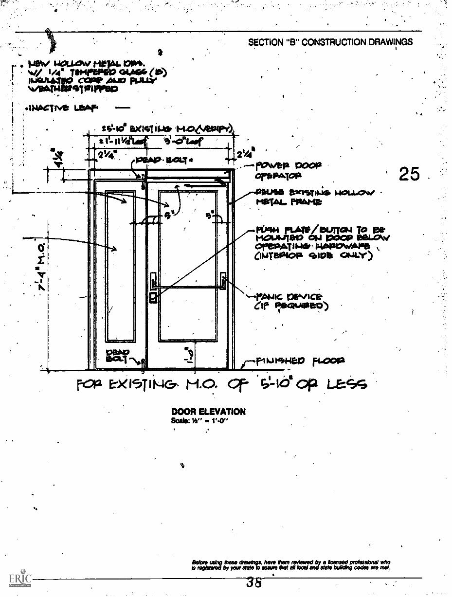
mew . mew. ms.r ivuow1 /411 Tempe Pep Goa& (p)
mime, CCM' AID pawenmprew
rvt LW* --t0.108 eX141 11.0 t-1426/601P0t II% 9i -0"lasf21/41.1
yr
a=masips
SECTION "B" CONSTRUCTION DRAWINGS
24e- rakV&P POOP
orfPAjola
PersfiNfil HOLLOW -116141. rPAMO
riATIP/bUrfad TO 1311.MOWNITEr0 014 MOP itiELOWOrePATIMer-1146P0411.436014.0401a "SOB GNAW)
peviceCis F:ocaullaeo)
/-1-I1J KS4e10 14.000
FOP' El<15T I MC7- H.O. Of" S' -1o' op LessDOOR ELEVATIONScale: It" a 1'4"
Before using these drawings, have them reviewed by a licensed professional whois registered by your state to assure Mai all local and state bulking codes are met.
84
25
SECTION "8" CONSTRUCTION. DRAWINGS
26
*Le
iFiCiuLTPPlisePPC01 TM"
0111110410,14 A PAM. 1111
flOWCPUI40 PPIACDO * IAt* 111040%/14
Oa
VgaNYITH
-etinot4 cows ea"Aimee Go swim)*DA CP 1101)04 4111011P41111' MOP 02. Aper4s.
al
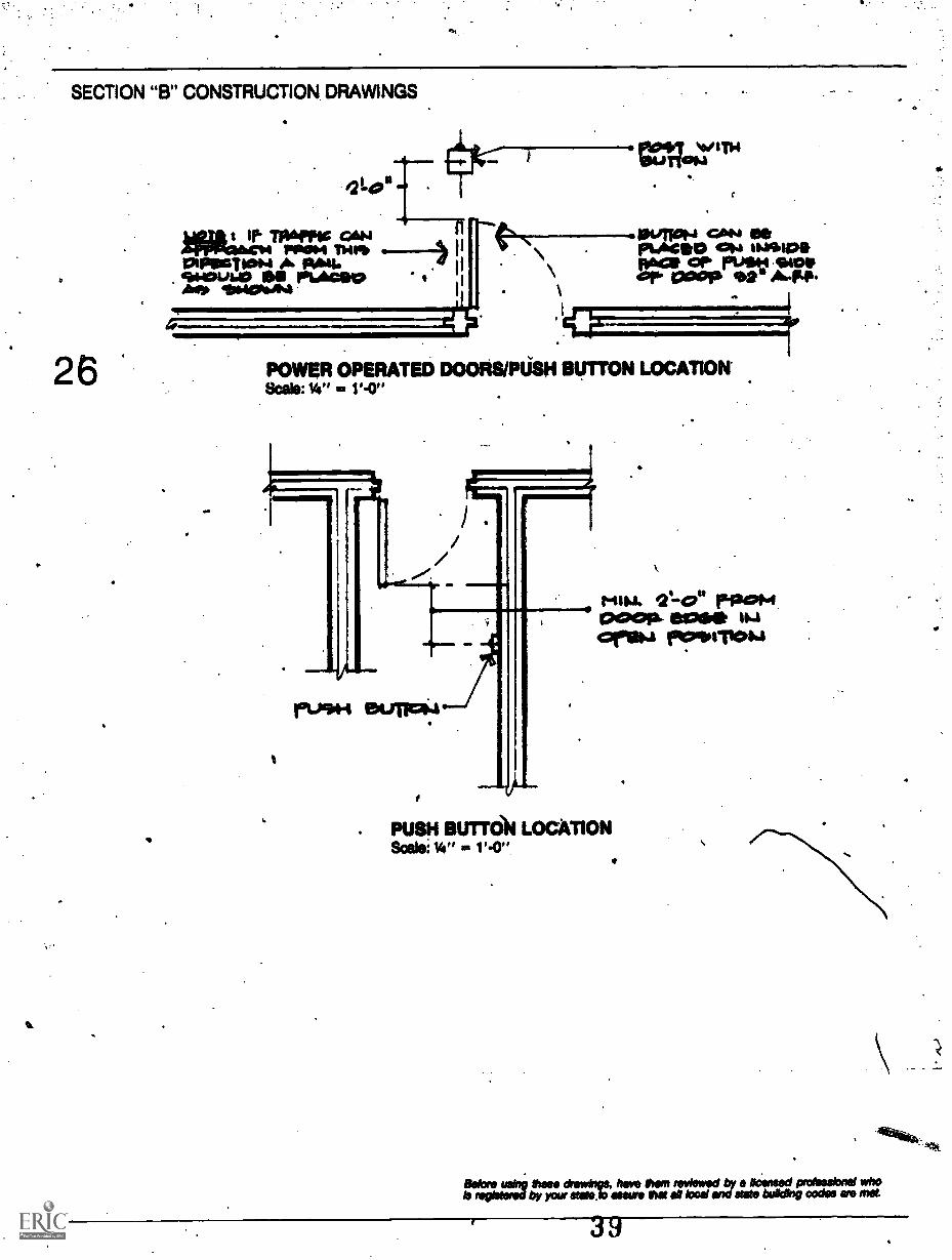
POWER OPERATED DOORS/PUSH BUTTON LOCATION'Scale: Vs" = V-0"
1
. 111
rusim eurfoi.4
Qt-e" riag+4poop- ea** 114
reollorrOM
PUSH BUTTON LOCATIONVs" = V-0"
Mont using these *swings, he them reWswed by *lensed prolesskwal whoIs reels.sred by your state .b assure that all loos, end state budding codes we met.
9

a
SECTION "B" CONSTRUCTION DRAWINGS
irst4r0081:7 GLIWA (Trre'D')
"IkV11011.191%,13:14tapiNe4.-
mew AtdCaloc.1114.6^WM. IMPB411401.0
11411010Ft
eLaV r120141.1 Y411)
THRESHOLD DETAS.Scale: 3" 1'4"
. 41
27
Bobs using mete drawings, We them rOylowo0 by a lloonood professional whoropy etwod by your stabs to sows est sit loos/ and Wets building come we met '
.st

SECTION "B" CONSTRUCTION DRAWINGS
ItbigneLL 14614, 1171A.M014iirKAU AtioUtiaNuti op
FIghoinet, WITH GNAWarDwit., ciwealash 4:9.1 LievoSligro..ser COO Imo.cAuus. up 10 4spitoolialiftcrin. roast_ ruaas
28
Ia
J.
,N1
es"
IND
r .;...
*X14TIMO STS. 1200P
1.0%%/ Valibt4/140P490FPIP To OSfigkaTemov TO 0001a .114401011.1Tel, 1-.14Tcs4 poop.
Piatiove ex renING.cAACOL-15: end VOTT 1w. MO
WilleJ111
DOOR SADDLE DETAILScale; 3" = '-0"
Vat1441140 !WM* beilk LeVal.
Gelpft. tile TO Zp001:160
Before using these drawings. have then, reviewed by a Moralised professional whoIs registered by your state ao assure that all local and state building codes are met.
41

Construction SpecificationsPlease note that the following specifications are notinclusive but represent items that should be includedwhere applicable when writing specifications foraccessible doors.
Fire -Rated and Emergency Exit Openings: Novidedoor units that comply with the requirements fordoors as emergency exits and do not interferewith fire ratings (if any), as certified by the .
manufacturer for the application shown.
Manual Door Closers: Spring power of each closermust be adjustable, Size II through Size W.Regulating screws shall be tamperproof andadjustable only with hex wrench. Closers shallhave separate adjustments for latch speed,general speed, and back - check. They shall have aback-check porting adapter valve to setcushioning of opening swing in advance of 90° forany standard mounting. All closers andaccessories, except special purpose types,whether applied hinge side, stop face, over door,or on bracket, shall be non-handed. Hydraulicfluid shall be of a type requiring no seasonaladjustment for temperatures ranging to *-30° F(-35°C). All closer cylinders, being non-sided,non-handed,.and with the potential forapplication in all standard mountings, shall beinterchangeable. All closers shall be from onemanufacturer and carry a five (5) year warranty.
Power OperatorsFunction: Automatic door operators shall beself-contained electric and/or hydraulic"slow-mode" operators designed for ,use by thehandicapped without need for safety mats orrails.
Doors shall open automatically by power andclose by spring or electric power. Operators shallalso function ts ordinary door closers at any time;during any mode of power operation, or whennot under power.
Automatic opening speed shall be adjustable toopen the door at a uniform speed from closed to90° open in 3 to 9 seconds. Adjustment time to berecommended by institution.
SECTION "C" CONSTRUCTION SPECIFICATIONS
Doors shall be held open for an adjustable periodof lime from 0 to 30 seconds. Adjustment time tobe recommended by institution.
Doors shall close by spring power with separatehydraulic controls for closing and latching speeds.Closing speedshall be adjustable to close the doorfrom 90° open to the latch position In.11/4 to 5seconds. Latching speed shall be Ws seconds togently close the door against its slop, andsufficient power to latch or hold the door in aclosed position.
Operation shall be by remote ush plate switches.Depressing the switch plate activate theopen/close cycle. Depressing the switch while thedoor is in the hold open position or is closing willrestart open/close cycle to cause the door toremain open for the full hold open period.
Resistance exceeding 15 pounds at the latch sideof the doorMall cause the operator toimmediately reverse its cycle.
Door Operator Installation: Disengage existing dooroperating mechanism, springs, and back-checkunit. Replace arms and pivots if necessary.
Disengage existing floor closets and checks and/orreplace with new pivots as necessary.
Size of Units: Except as otherwise specificallyindicated,.comply with the manufacturer'srecommendations for size of door control unit,depending upon "size of door, exposure toweather, and anticipated frequency of use.
Electric Door Operators, Sliding: Manufacturer'sstandard electric drive unit, self-contained withconnections for power and control wiring, poweropening and either power or,spring closing withsafety release clutch for obstructed closing, andwith checking for both opening and closingcycles. The operator(s) shall allow the door(s) tobe operated manually in power on or power offconditions.
Breakaway Device: All sliding door leafs shall beequipped with a panic breakaway deviceconcealed within the top of the door. The slidingdoor leaf(s) and the swing away side light(s) shallhave a concealed shock absorber control arm
9

SECTION "C" CONSTRUCTION SPECIFICATIONS
3
. mounted in the top rail to control the swing arcwhet doorls) or side light(s) is in panic mode.
Door Operator Controls aird AccessoriesPusb Plate: Provide press type wall plate switches(two per door) with adjustable ti,e delay' (holdopen).
Electrical Interlocks: Wherever feasible, provideelectrical interlocks that will prevent operation ofunit when operation of door is prevented by lockand latch or door bolts. If this is not feasible,
provide key switching at door location to shut offpower when the building is locked.
Electric Strike: Provide an electric strike to permit. opening and closing a door automatically that issecured with a latch or bolt, with separatesolid-state interfaie control. This specificationshould be used if door is to be automated.
ThresholdsSitelProfile: As indicated or, if not indicated,manufacturer's standard for condition ofexposure.

ak
Chapter 4 ,/
114TERIO*CIRCUIATION
Interior DoorsInterior door in the path of acrerequired to meet the requiremen
ble travel are(p. 21).
Horizontal Circulation SpacesNeeded for Program A - ilityIt is necessary to provide an accessible path of travelinside the building to any and all spaces required tomeet program accessibility. This does not mean thatevery space in the building has to be accessible.Once the building entrance has been established,you should ascertain which floors of the buildinghave to be accessible, and then determine if thesefloors can be reached by a mobility-disabled person.
Within those areas required for program accessibil-ity, floors, . hallways, and passageways should bebarrier-free without abrupt changes of level. Roomsand spaces needed for program accessibility shouldnot be at a different level from hallways unless theyare properly ramped or chairlifts are provided.
Floors above and below the entrance level must beconnected by ramps or elevators to be consideredaccessible. If these floors are already connected byramps or elevators, the elevatorsand ramps have tomeet the minimum requirements listed under theappropriate criteria section.
If there are two levels in a building and two differentfunctions take place at each level, and each level hasits own accessible entrance, then it is not necessaryto have accessible interior vertical circulation. Forexample, an administrationklassroom buildingdoes not need interconnecting interior circulation ifboth floors are accessible by external entrances, buta physical education building with locker rooms onone floor and gym facilities on the other would needinternal vertical connections that are accessible.
StairsAll stairs, except those in an enclosed stair tower,should have a tactile warning at the tOp of the stairrun. The tactile waft% can be a charge of texturein contrast with that of the path of tralVel leading tothe stair. If this path isTarpeted, for; example, youshould change the texture by removing an area ofcarpet a distance of three feet from the top step andreplacing it with tile or some other hard surface. Acolor change as well as a texture change will makethe tactile warning more apparent to the partiallyblind.
Edges of Dangerout Low AreasThe edge of areas such as reflecting pools shouldalso have a tactile due or warning to prevent a blindperson from stumbling into the pool. This tactileclue could be a curb, a rail, or a texture change.
Protruding Objects in Path of TravelThere is a danger zone for blind people using theTong cane technique. This danger zone is caused bywall-mounted objects that project into the path oftravel. An object such as a telephone booth or drink-ing fountain cannot be detected by the long cane ifthe protruding areas of the object fall entirely withinan area 27 to 80 inchesabove the floor. The objectthen becomes a hazard to a blind person. If a wall-mounted object does fall within this danger zone, itcan protrude only four inches from the wall surface.
a,All hallways, corridors, and aisles should be exam-ined for objects that fall into this category.
If an object extends to below 27 inches from thefloor, the long cane technique will detect it. Objectsprojecting into this lower area can protrude anydistance from the wall without becoming a hazardto the blind.
31

SECTION "A" EVALUATION OF THE EXISTING BUILDING
32
Objects such as signs shall not extend down fromthe ceiling into the upper range (below 80. inchesfrom the floor) of this danger zone.
Removing Protruding Objects in Hallways
Vertical Circulationthe ElevatorIn many instances, elevators are required for verti-cal circulation. For new construction or installationof a new elevator in an existing facility, there areother standards that should be applied, but foreither of the above instances, we are concerned onlythat the existing elevator meet minimum require-ments required to piovide safe and accessibletransport.
O size (as shown on page 33)
O door shall provide a 32 inch minimum clearopening
0 accessible to entrance of building
O space in front of elevator at least 5 feet wide by 4feet deep
O elevator must level within t Va inch
O height of controls should not exceed 48 incheswith the emergency stop control at bottom.Where elevator buttons can be operated with areaching stick (provided by the institution), 48inch height requirement extended to 60 inches
10 door must have either a safety shoe, photo-eyeor other means to stop it from closing on personsentering or exiting. Side hinged rather than au-tomatic sliding doors must meet all criteria for doors,If there is a retractive gate, it cannot require more than
lb. opening pressure. If these criteria cannot be met,the institution has the option of providing attendantoperation or installing a new elevator car.
As a general rule of thumb, a 1500 lb. elevator willprovide minimum accessibility for an existing facil-pty
Often it seems as if a new elevator will be requiredfor a building you are investigating. In many cases,programs have been transferred to other buildingsor to the first floor of the facility so that this newelevator is not needed. In other instances, it wouldbe unrealistic to move the programs i.e., special-ized laboratories on the second and third floors of abuilding would be expensive, if not impossible, tomove.
Accessible Elevator Controls
IMO0110.).
HEIGHT OFLOWEST
11113/-35
MAXIMUM 48" TO BE USEDWITHOUT A REACHING STICK4MAXIMUM 50" TO BECONSIDERED USABLE WITHREACHING STICK

SECTION "A" EVALUATION OF THE EXISTING BUILDING
Minimum Elevator Criteria
Note: The 4'4" x 4'4" (1800 lb elevator) and 4'4" x 5'4"(2000 th elevator) w$H not allow a wheelchair to turn around, butWI be acceptable as a means to comply with 004 In edgingstructures.If a 36" clear opening door Is provided in an existing elevator,the depth of the elevator can be reduced to as little as 46" if thewidth of this existing elevator exceeds 5'4".
a t.
4,6

SECTION "B" CONSTRUCTION DRAWINGS
34
Wheelchair LiftsWheelchair' lifts can to used (local or state codespermitting) when the e is not enough space for a
I properly designed ramp. It is essential that the lift' be safe and reliable. There are two types currently
available:
A lift that operates like an elevator tv:rtironv). As manyof these "lift-packages" come,%vitt out safety fea-tures, you should verify thaVthe following are in-cluded: safety gates that prevent anyone from en-tering the lift platform unless It is at the same levelas the gate; cut-off controls to stop the lift if itcontacts an obstruction while lowering, and a man-
.
4
ual mechanical override so that a person using awheelchair Can be rescued if there is a power orequipment failure.
A lift that travels up a flikht of stairs. The most impor-tant considesation relating to this type of lift is thatthe stairway is wide enough to accommodate boththe lift and able-bodied use if the stair is needed forfire exiting. The decreased width size of the stairshould comply with applicable local codes. Thistype of lift should also meet the requirements of thevertical lift. If the lift is to be used independently by thedisabled, it shall be able to be summoned from eitherstation without the platform being folded in an uprightF.
VERTICAL WHEELCHAIR UFT
INCLINED STAIRWAY WHEELCHAIR UFT
Before.uoingle mimeo be ydatwe
ingo * , hWave a reviewed by licensed prolegelonal *iva I local WWI state building COOPS ere met

ga
We Aug. PAIL. 4P.*4UU
I s/411 Aum4. poop..
se
446
SECTION.13" CONSTRUCTION DRAWINGS
asvhcideis
01111UPM PAIL. 10\NIAIA. A,T Iwo%
806 WM. CLOR
*9 .119 de 04.
/*CONIC. SLAID mir/, 4/4 \N/NNIP 1111:
epo 11.440,.. foPM
I.1. .4 J. .
L614T 0.40+4T C014$ *4
. ."
evc.4012124)4047012 M 1M. FOP*, .41AlVi*4 atoso.a.caktotrus
INTERIOR RAMP SECTIONscab: 1- go '-o"
Before using Owe diewargs. Asve Chem misread by a licensed professional whois naglaredby your stets b mews that al bold and stets building codes we met

* t
SECTIO C TRUCTION SPECIFICATIONS
36
ons S
These fications are not all inclusthose areas that should be included-for baaccess.
ElevatorsDoor Protective and Reopening Device: Elevator doorsshall open anti close automatically. They shall beprovided with a reopening device that will stopand reopen .a car door and hoistway doorautomatically if the door becomes obstructed byan object or a person. The device shall be capableof completing these operations without requiringcontact for an obstruction passing through theopening at heights of 5 inches and 29 inches (125mm and 735 mm) from the floor. Door reopeningdevices shall remain effective for at least 20seconds. After such an interval, doors may closein accordance with the requirements of theAmerican National Standard Safety Code for ElevatorsDumbwaiters Escalators and Moving WalksA17.1-1978.
4
Height: All floor buttons shall be no higher than 54inches (1,370 mm) above the floor. Emergencycontrols, including the emergency alarm andemergency stop, shall be grouped at the bottom ofthe panel and shall have their centerlines no lessthan 35 inches (890 mm) above the floor.
Locations: Controls shall be located on a front wallif cars have center opening doors, and at the sidewall or at the front wall next to the door if carshave side opening doors.
Door and Signal Timing for Hall Calls: The minimumacceptable time from notification that a car isanswering a call until the doors of that car start toclose shall be calculated from the followingequation:
T =1.5 ftis
(Eq 1)or T 455 minis
where a
T = total time in secondsD a distance (in feet or millimeters) from apoint in the center of the lobby or corridor 60inches (1,525 mm) directly in front of thefarthest call button to the centerline of thehoistway door. For cars with in-car lanterns,"1" begins when the lantern is visible from thevicinity of hall call buttons and an audiblesignal is sounded. The minimum time for
elevator doors to remain fully open shall be 3seconds.
Inside ofCar: The inside of the car shall allow forturning of the wheelchair. The minimum cleardistance between the walls or between wall anddoor excluding return panels shall not be lessthan 68 inches (5 feet, 8 inches) x 54 inches (4 feet,6 inches). Minimum distance from wall to thereturn panel shall not be less than 51 inches (4feet, 3.inches). .
Hall Call Buttons: The centerline of the hall callbuttons shall be centered 44 inches above the floor.The button designating "up" shall be located on thetop.
Direction buttons, exclusive of border, shall be aminimum of 304 inch in size, raised, flush, orrecessed. If recessed, the button shall not berecessed more than 3/s inch. A visual indicationshall be provided to show each call registered andshall be extinguished when the call is answered.
Hall lantern: At each hoistway entrance a visualand audible signal shall be provided to indicatewhich car is answering the call and its direction oftravel.
Note: Some systems are set up so that the car will notstop at the call floor unless it has no other preinstructedtravel orders. In this case, no direction ht will benecessary but an audible signal show provided. Thevisual signal for each direction a minimum of21/2 inches in size and visible the area of the callbutton.
The audible signal shall sound once for "up" andtwice for "down."
The centerline of the fixture shall be located aminimum of 6 feet above the floor so that it maybe seen by a person seated in a wheelchair: In -carlanterns may be used if they meet the abovecriteria.
Door Jamb Markings: At each hoistway entrance(on both sides of the jamb), a floor designationshall be provided at a height of 60 inches (5 feet)above the floor.. These designations shall be tactile(raised a minimum of 0.03 inches), in highcontrast with the jamb wall, at least 2 inches highand visible from within the car and the elevatorlobby. Permanently applied plates are acceptable.
Car Position Indicator and Signal: A car positionindicator shall be located above the car operating

\ SECTION "C" CONSTRUCTION SPECIFICATIONS
4 panel or over the door opening of each car. This \ was either stopping at or passing a floor served byindicator shows the position of the car in thehoistway by Illuminating the number of thelanding where the car is stopped or passing at thetime. This may be a LED (Light Emitting Diode)display. The indicator numbers shall be in highcontrast to the background and 'shall be aminimum of 1/a inch in height:
Handrails,: Although not required by the newANSI A117.1(100), handrails assist those withsemi-mobility handicaps. A handrail, if desired,should be provided on at least two sides of the car(preferably on one side and the rear of the car).They shall be smooth and the inside surface shallbe 11/2 inches from the car wall. They shall bemounted at 32 to 33 inches above the car floor.Note: This shall not interfere with any controls as thelowest control is 35 inches above the floor.
Audlblq Floor Passing Signals: An addible signal canbe provided to indicate that the car is passing afloor. This signal can be subject to a special buttonin the car operating panel which, when pushed,would indicate to a blind passenger that the car
signal
This special button will restrict the\aignal to sounding for a trip in one direction when
button was activated.
Ejawslowestemergpart of theach callcall is answ
or Car Button: The highest button inside theuld be 54 inclies above the floor and the
tton 35 inches above the floor. Thegroup shall be located on the lowest
nel. Visual indication should showred and be extinguished when the. Markings should be adjacent andcontrol on a contrasting color
rs or numbers shall be ach high raised or recessed 0.03
to the left ofbackgiound.minimum of 1/4inches.
There has been some r4 'greement as to whether Brailleshould be used to identify the butkins in elevators. Butmany blind people cannot read Braille and time whocan, can also identify raised numbers. Therefore, itappears that Braille is an extra expense that is notrequired. If Braille is used, the plates should be attachedwithout protruding small rivets or screws, as they
- could be misleading to a Braille reader.
37

Chapter 5
RESTROOMS
Restationts(21 One male and one female restroom shall be
provided on the same level as the accessiblebuilding entrance, or, if there are no'restroomson that level, on the next closest accessible levelwith restrooms. If a building currently does not.contain restrooms for anybody, it is not neces-sary to provide them solely for the handicapped.
0 For a restroom to meet accessible design criteria,it must be on an accessible floor and have anaccessible entrance as well as meeting the basiccriteria listed below.
If there are existing curtains on the accessible stalls,they shall be acceptable if the stall is a 'minimum of 4feet 8 inches long by 3 feet wide and meets all othercriteria. This is hot a recommended solution as itdoes not provide the same degree of privacy and thecurtains are an easy target for vandals, but the Of-fice of Civil Rights accepts it as a solution because ofthe lower initial modification cost.
If an existing male restroom has a stall that meetsthe minimum criteria, it is not necessary to modifyeurinal in that restroom.
As toilet.seat heights are changed fie new ANSIstandard, it should not be ntcfssary to modify seatheights that fall within the rage of .17 to 20 inchesabove the floor. I
In large buildings where a disabled pers1 mighthave to travel an inordinately long distance on onefloor, and if there are several male and female re-strooms on each then consideration should begiven to making additional restrooms accessible.
In buildings over five stories high, a restroom.loreach sex should be provided every fifth story. This
is a general rule, but it. sluiuld also reflect the needsof the institution and the specific building. This ruleof thumb is not meant to reflect the time that adisabled person needs to get to a restroom butrather the number of accessible facilities needed as aminimum in a modified facility.
A unisex restroom is also acceptable if it meets theappropriate criteria and:
is acceptable by local or state codeis usable by everyone and is not set aside forthe dimbled
Note: The 5 feet by 5 feet turning space can be reducedabove the /Thor level as shown by this diagram. This willallow placement of lavatories and other restroom acces-sories in this area without violation of the 5 feet by 5 feetrequirement.
Wheelchair Turning Clearances

.SECTION ...A" EVALUATION OF THE EXISTING BUILDING
%
40
The Entranceway and RestroomFloor Layout.
4
Restroom entrance door must have at least a32 inch clear opening (see Chapter 3/Doors).
Internal passageway vestibule (if required) mustallow access (see illustrations below).
There should be a place in the restroom where 5feet by 5 feet level clear floor ,arpa exists (seesketchtpage 39).
Restroom Floor Layouts
RESTROOM
WAU. OR TOILET PARTITION
48" MINIMUM.
VESTIBULE
HALLWAY
RESTROOM
HALLWAY
VESTIBULE
HALLWAY
RESTROOM

SECTION "A" EVALUATION OF THE EXISTING BUILDING
0-614b bars:"a", "c" stall mounted horizontally both.sides,
"b" stallL-shaped ho-rfzoiltal grablbat)
0 Toilet seat:17 to 20 inches above floor level
Toilet StallsO Stall door shall have a minimum 32 inch clear
opening.
O Stall door: swing out (curtains in existing situa-tions only)
O Stall size:"a" stall 3 feet wide by 5 feet 6 inches long, or"b" stall 5 feet wide by 4 feet 8 inches long, or"c" stall 36 inches wide by a minimum 8 feetlong.
32w' CLEAR OPENING
Note: An existing curtain is acceptable if the stall is aminimum of 4 feet 8 inches long by 3 feet wide and meetsthe rest of the criteria.
1Accessible Toilet Stalls
32" CLEAR OPENING
3'.1" MIN.
5°-0" MIN.
"C"
89-0" MIN.
38"CLEAR
OPENING 4'-0" GRAB BAR
END STALL
a GRAB BAR HEIGHT 32"
e17" TO 20" TOP OF SEAT HEIGHT
Note: An existing curtain is acceptable if the stall is a mieimumof 4'8" long by 3'0" wide and meets the rest of the trite a.

A
I
-AO
I
I
I I .4._ : to
I f I I I _ I I LI I
1 I ...,___1. I I .
. I I I
Ir I -ti
I I
I
1
1 °I
711166 mmmm
..-Lt
I
1 I
t.af A1-1-1.1117-iliAA.`_1E1-1-7
Oa:
Fa.
-
I I
. I
I
I
I
I -e I I I 11
u_ II
N
w.14_
4

SECTION "A" EVALUATION OF THE EXISTING BUILDING.
0 Accessible handle for faucet (as shown below)
0 Towels and dispensers 48 inches above the floor(as shown below)
ra Drain pipes protected or insulated if 120° orgreater
Minor mounted with bottom no higher than.40inches above the floor or tilted mirror
PAPER CUPDISPENSER
1 Maximum 18 inches from lavatory front to faucet(as shown on page 44)
Note: If possible, the towel dispensers should not belocated whereat person has to reach over the lavatory. Thetowel dispenser also should not be located across therestroont, but rather on the wall adjacent to the lavatory.This frees a person using a wheelchair from having to usewet hands to propel the wheelchair to the towel dispenser.
43Accessible Handles for Faucets
ELECTRIC HANDDRYINGEQUIPMENT
C21'OWEL
WASTE
Controls Viiihin Reach
TOWEL DISPENSERNOT ACCEPTABLE.PROVIDEALTERNATE MEANSFOR HAND DRYING.
'0"LIGHT SWITCH
IMMOISIMM
3
SANITARY NAPKINPAPER TOWEL VENDING MACHINEDISPENSER SANITARY TRASH DISPOSAL
TOWELS
\"*".40.11
NAPKINS UNIT
INN--7/1\,TRAsH
Note: Highest operable part shall be centered on or below 48"

SECTION "A" EVALUATION OF THE EXISTING BUILDING
44
0
Accessible Lavatory Dimensions
56

66MSW. --1-
i
OINI.10
SECTION "B" CONSTRUCTION DRAWINGS
11/rue 0141WPW.iistirVer 1401441100IMAller_ _OW 04 crease'VO --rmiAcm reoul t tWrrticurKimmel erstegv esoss-
1_.Mtn". rA,TITIO140a10 644Ver Paillq-14013400
. al Na6000. ON elovrima004 TI-11:2J WITH ecenG,617SUPPOP4
0111111
Mimmimbompl 40,=10001.1...
TYPICAL TOILET STALL DETAILScale:11/2" = 1' -0"
Before using these drawings, have them reviewed by a licensed professional whois registered by your state to assure that all local and state building codes are met.

SECTION "8" CONSTRUCTION DRAWINGS
IO2"
46
TMIS DIM i1ON GAS.1e 36/ 8"
- Sten 12
1/02 s vite *IkePP10P1 WAIL
ept.e0111 C.Vol" P-1114. PLOOla HT. NV.C..
400smo.I.
.466 I fre 'I.., I Jos GLS0442.chmaariaom \Wm.&
se," 41460WEI W01..t. 1)0440 di?" axles
WET \14L1..-STALL "A"Seale: IV a. V-0"
it
92N621:xxs= cliss or riemsma. .
laittiovek ToiLaT4 120004 IN TALI. 1.1ft metro,. ,
pagappoN Aweviusweho Amp11.141;61.41 146. OVA. sea
Pitiocisie axisre. 194.00 12411110111P
STALL "B"Scale: 1/2" a. 1, -0"
LIC233.1IP Nov tapir sTION 00. %A MIDW1114007 peapromalcuL.A.rapiLA4TB. Woe' 46' Grua atakHooKeD 1' FVOM peso wou.i.
1403.1ALI
1/BlErriA4,.". RAJ.
f`11 P.4, 440"
IP FUJei-1 11JTePPE1204 solqw 4041) SOP- I ?" la I )4" I ke CMIAPalkiee HAY co uq490,
Before using these drawings. have then, reviewed by a Imbed professional whob registered by yox state to assure that all local and stab building codes are met.
58
O

1.404. 746 WAU. ouuti.S'.011 pcoo. mar: w. C.
SECTION "B" CONSTRUCTION DRAWINGS
Siiistr) 0P 126ST1A2VPI
14-
3
r.0i e/MaND 01.11.10 al.W10 4.OMNI 410/0 11111110 0101 01111.
10412CLaohnGor0041144$
0.111.11.
4746" GP". essaiI Ps" cutoboetwe
a
STALL "C"Scale: 1/2" 3. 1'4"
Mo
TYPICAL CONVERSION FROM 2 STALLS INTO 1 ACCESSIBLE STALL
eeNrois refits:eV :°;:ulreirelt:resnreure Nest el local enrettlfbuildIng codes are
59

SECTION "B" CONSTRUCTION DRAWINGS
48
a
reikPAHIc7/40PlAva
111. L.-.
.
cowcPeTe. SLS4.
TYPICAL EXISTING SHOWER CURBNot to scale
-1cePAI-IIC 'pt.&To timcm ex149.14;
mom,* veto r,es)(14T h1 cum.
p40004 R4101012 pes4.4:40.114PeroM*1.12 MOW. I" MOM
AT &ACI-I COPNraia.ILVrSMOOTH SL.Cfe
bier eXISTINO. ri..01:11ae
cONCPOT ft' SLAB.
MODIFIED ACCESSIBLE SHOWER CURBNot to scale
Before using these drawings. have them reviewed by a licensed professional whois registered by your state to assure that all local and slate bulldog codes are nut
60
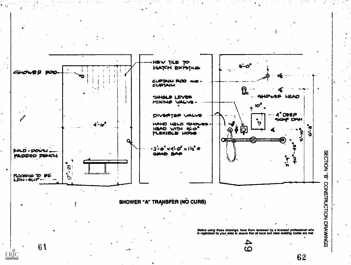
11,
cmesee P Poo
,4
P01.4i 12C4/14MOO ep feeNcs4
.61
a ;lacatwer ir
61
4
4=1"
New Ttt.e TeHA'S'H &xesaill..1E
a iJP16411 PA00 **.aoCuP14414
L.S.VetaVALVE
s .
II
4._
41401./Sia I*A0
a4" DeeP4ftear prim
4 42
.1111011100MI
SHOWER "A" TRIVISFER (NO CURB)
I
a
io
Before using these drawkvs, have Mem reWewed by a Licensed professional whois registered by your state to 868411* that all local and state building codes are met.

4" CONC.OCK WA1.1. WITH
6010shHIC 111.6
01 . .
- COPAHIC 441.0reDvpAwsp-toTcm eximsmav
-7":""m"";16110111iiii 1161UMWersraimplassimiur...mob mom., -
"A" SHOWER DETAILSeale:1" =4 1*-0"
a 4.
*ea 1011 1.11 Omar*4. A
eTecoors "LAOduorpo aro allatkii..1
CAOK 112014 120k6.11J14/1/1.1 9rPA10.4.1a.
WPM'. ilt.141= IAN.1... AMP PC:icZITHOOL Rou.0411.4 41'4144
Bala4 using thins drawinge, have Own isoed by lisonsd pi's:kabinet whois r0 by your stabil saw. Mid at Awl end kitty codes to nut

Pi re
SECTION "B" CONSTRUCTION DRAWINGS
4,HOW Dia P'1 ALL4:01a 4Ne rAaRallre
1XTU Peep .
war.. 4I wow. 1lb1
°,%40152 PET
floW 1"44)ROP
AohAvIkirpowur 4131kA.
INIM4M.
=11.1111=1.
_
it
10
ff-
1.tizec rt.*et.4"1
.M41
Wire; :AOTTEP 1448.> 442.441 Togo sacierriNci6140WEIC
"Er SHOWER DETAILScale: 3/4" = 1'0"
4
Before using these drawkrgs. have them reviewed b y a licensed professional whois registered by your stale to assure that all local and state building codes are met.
51

SECTION "B" CONSTRUCTION DRAWINGS
52
cuPrAika ao0
CO
eLevAisoki
"B" SHOWER DETAILScale: 44" = 1' -0"
O
Before tieing these drawings, have them reviewed by a licensed professional whois registered by your state b assure !hat all Wei end state building codes met.

SECTION "B" CONSTRUCTION DRAWINGS
Ciica lacw NA pop a
M
11-' 314
za.
6PAet luso%nee .p.
Skviwcyup"egg
1..E\/A1* ION
"B" SHOWER DETAILScale: 44" = 1, -0"
0
4
. 53
`21
Setae using these drawings. have them reviewed by a licensed professional whois registered by yow state is assure that as Wei and state building codes we met.
7

SECTION "B" CONSTRUCTION DRAWINGS
Attaching Grab Bars
In 'the past, little attention has been paid to thefastening of grab bars to the walls and partitions.inrestrooms. Because of this, in some instances, grabbars have pulled from the wall or become loose. Themost secure way of fastening the grab bar is toinstall a steel date in the structural system of thewall and bolt the grab bar to the steel plate. Bolting
into solid wood structural members 'provides thenext best alternative.
For metal and plastic laminate toilet partitions, thrubolting should bt used (with spreaders used in themetal partitior0
If thru bolting with steel plates is not feasible, heavyduty anchor shields should be used.
No TE-TH& pes1 1.4101.400 PG INA4TALLAT low *1 WOOD OR1411-17a4.0 Si WC; WALLS ITIP " \%4640L. BerTWO944STUD Da Ukalsee Amcwom rusredspeowiatits q.rups, serope \4n4 -L us APP10.11142pecess Amch, to ecRUIPaer12 piolo p4414W4Mort.SCAT IOW
ROUND
STUD WALLS WITH STEEL PLATENot to scale
lE
goLOCIA WALL.
BLOCK OR MASONRY WALLSNot to scale
Before using *We dewing*, have thorn reviewed by a licensed professional whoN registered by your state io assure ma ail local and state building codas,* met

aECTION "B" CONSTRUCTION DRAWINGS
2- /4 *2 FLATEroWirX we L.A0S. IDOL.Tep
IrmaWALLS WITH WOOD SUPPORTSNot to scale
1-1eX 1-060 1-1441.41 We QC1a6\/f.
ANCHORING DEVICE AT METAL PARTITIONBACK TO BACK GRAB BARSNot to scale
55
Belprerepl4ereiby ° drawint have that all keel encliac building codes are 17:etwe
69

SECTION 13" CONSTRUCTION DRAWINGS
56
coe pur
ANCHORING DEVICE AT METAL PARTITION WALL. Not to scale
2 %4 - 20 vc 2" FLAT& 54661.. I-IkX 61640M CHINE SGP rieVe5
I
ANCHORING DEVICE AT MASONRY WALLNot to scale
Before using Mast drawings, have diem reviewed by a licensed professional whois registered by your state b assure that all local and state building codes are met
70

Lavatory Selection and CriteriaThe most universal and easily used lavatory allowsa person's legs to project under the lavatory. Thisfront approach is preferred by most people becauseit permits closer access to the bowl and faucets.Most people find it comfortable ,to sit 4 to 8 inchesfrom the front apron of the lavatory.
To allow clearance for a person's knees under thelavatory, a clear unobstructed space of 271/2 inchesabove the floor measured back from the front aprona minimum of 8 inches should be provided. Thiswill allow a person using a wheelchair to comewithin '5 inches of the front apron. This 5 inchdistance is measured from the front of the apron tothe person's midriff. The knee clearance of 271/4inches above the floor should be measured backfrom the front apron 8 inches-until the front face ofthe bowl is encountered. The clearance should notbe measured to the face of the front overflow part ofthe bowl, but 3 inches off the centerline of thelavatory, because a person's knees are not normallyheld firmly together but are separated slightly. Ifthe bottom of the front apron is located at 29 inchesabove the floor, those using bench type arms ontheir wheelchairs can get even closer.
The preferred height of the rim of the lavatory is 32inches above the finished floor, but most of thelavatories manufactured today will not allow this 32inch height to be met without violating the 271/2inch knee clearance. A maximum rim height of 34.inches above the floor is acceptable if the 271/2 inchknee clearance cannot be met with the 32 inch topheight.
The lavatory shall project a minimum of 17 inchesfrom the wall, so that the person using a wheelchaircan get close to the lavatory front apron without thefootrests of the wheelchair hitting the rear wall.
There are three types of lavatories that can be usedto provide accessibility:
Wall Hung. (Vitreous china or enameled cast ironlavatories). These units can be hung with wallhangers or chair carriers with concealed or exposedarms. When an existing lavatory is replaced, itshould be checked to determine whether the re-placement lavatory will fit on the existing chair car-rier (in which the height can be adjusted), orwhether a new carrier will be required.
SECTION "B" CONSTRUCTION DRAWINGS
Stainless Steel Combination Unit
75.w,
18"
There are sever,1 20 inch_by' 27 inch wheelchairlavatories currenlly 4vail4tle. These units require achair carrier and takettp 9 *hes more space than astancilard 20 inch by 18 inch unit. This space re-quirement could be a problem in a small restroom,and some disabled people have complained thatthese units are difficult to use.
Stainless Ste(l Combination Units: These units cancome with towel dispensers, mirrors, soap dis- .pensers, blade or lever handles, and trash dis-pensers. They are rectangular and have protecteddrains concealed within the unit. The lavatory pro-jects out 171/2 to 22 inches from the wall and thenarrow width allows close approach.
Countertop Lavatories: This type of lavatory can beaccessible if the countertop is designed without adeep apron. The same clearance restrictions thatapply to wall hung units apply to countertop units.;lie main advantage with a countertop unit is thatan extra 2 or 3 inches of higher clear spice can beobtained in front because the lavatory bowl is setback from the front apron.
57

1.
SECTION "B" CONSTRUCTION DRAWINGS
58
COUNTERTOP LAVATORY
Before these drawtngs, have them reviewed by a licensed professional whoSr by your state to assure that al local and stets building codes are met.

eJ
131404*141=4,80,49&
axles*, gurrve----ripeak "el) OariaJOBO
&xust412?Ire as ineguipeo
SECTION "Er CCNSTRUCTION DRAWINGS
4136PLACIA 14A1.110L11. verri4°worm wit.sos.ladr.mievimas. softwaLe moorcometyge
Ewe 4A).0412, cClalft"LeAo explawamw
patiate itsvoix. AiwaassicoT wait-igloo
MXIdb11142. chilfirtYnee.
Nei -TPA,'
Widsvi Miro CesteHic '1IL rtoeta
4
won- cemmic ue
ex 104 INSIP
1461.1rivega
geT Weld \ALAI*por a". TO WeLL
rosemeka
iOs LAM To est 141,JtJefp A T Tgar.1.0101-11 .61110aselt
EXISTING TYPICAL LAVATORY MODIFICATION DETAILNot to scale
ittris=1 ibilyegirdrest:teiterathXdriotTe="8"Projasskre w"°
59

SECTION "C" CONSTRUCTION SPECIFICATIONS
60
Construction SpecificationsThe following specifications are not.all inclusive. Theyrepresent certain standard items that should be includedas apptiaible in any specification for restrooms that areto be made accessible.
Toilet and Shower Compartments: Constructed Asdrawn for toilet partitions except that door clear.opening shall not be less than 32 inches wide andthe door shall swing into the toilet room. Doorsshall be equipped with spedpl hardware ofmatching finish, and handles on both sides of thedoor shall be provided for ease of entry. Panelsshall be reinforced for grab bars.
Equip each new or remodeled compartment witha rubber tip coat hook, located no higher than 54inches above the floor. Provide each door withslide tar latch and keeper. Hang doors onconria_gravity hinges. New hardware shallmat existing hardware. Existing hardware maybe reused where acceptable to architect. Providetheft-resistant fasteners for exposed accessorymountings.
ifrinforcernent: Reinforce walls and partitions forgrab-bars, towel dispensers, and folding seats.
Reinforcement shall be hardwood or steel plcie.Provide 8 inch wide strips for grab bars, cent ed2 feet, 9 inches above floor.
Water Closet Seat Lift and Seat: Water closet seat liftto include total integral unit consisting ofindependently hinged riser seat andindependently hinged elongated open front seat.Solid plastic seat fitted with hollow core plastic liftto match the configuration of existing or newwater closet and which raises the top of the seatabove finished floor to 17'/2 inches. Hinge of seatto 6'e check type. Both seat and lift to raise. Liftand seat to be whit;.
Note; Wherever possible, the existing seats shall bediscotanected and reused with the new lift. All existingitems snot reused shall revert to the owner.
Shower Stalls and Shower SeatsShower Stalls: 36 inches by 36 inches. An accessibleshower stall shall be equipped with a hinged,fold-down, padded bench seat with retaininglatch or hook-and-eye, which maintains anupright position when not in use, located at frontedge of shower bench within easy reach of.18inches (45.7 cm) in height from the stall floor leveland mounted on the stall sidewall opposite that ofthe main showerhead and controls; showercontrols usipg blade or lever type handles that aremounted no higher than 40 inches (101.6 cm)above stall floor level; a hose spray of at least 5feet (152 cm) in length with a nozzle hookmounted 40 inches (101.6 cm) above the floorlevel; an accessible threshold,Of either not over 1/2inch (1.27 cm) in height or ramped to conform tocriteria; and to recessed soap dish and a utility areaof at least 6 inches (15 cm) deep, 10 inches (25 cm)wide, and 12 inches (30.5 cm) high. All controls,showerheads, and recessed areas shall be locatedon the wall opposite the fold-down bench seat inthis stall which has a maximum width of 3 feet (92cm).
s.
Folding Shower Seat: It shall fold .up against thewall or down for seating. Frame, supports, and
91)
rackets shall be satin finish type 114 stainless(steel. Seat shall be 2 inches thick Naugahyde-filled with rubberized hair, mounted on marineplywood.
Shower grab bars shall be located so as topermit the seat .J be raised.
Grab Bars: Grab barsshould be provided with anon-slip gripping surface.
All grab bars shall have an outside diameter of1% inches.
All grab bars shall hav,e-qncealed mountingsand be installed in strict accordance withmanufacturers' recommendations.
Bars shall be able to sustain a dead weight of250 lb. for five minutes at any point.
Sizes and shapes as indicated on drawings.I.

Bar shall be 11/2 inches from wall.
Manufacturers shall furnish all plates, anchors,and fasteners required. Concealed items shallbe noncorrosive.
All exposed screws and bolts shall havetheft-resistant fasteners.
Shower grab bars shall be located so as topermit the seat to be raised.
Lavatory and Trim (Handicapped): Under eachaccessible sink thpre shall be a minimum kneeclearance (taking into account both the counterapron and the bottom of the basin contour) of
4
SECTION "C" CONSTRUCTION SPECIFICATIONS
271/2 inches (69.8 cm) vertically for a horizontaldistance of 8 inches (33 cm) from the front edge ofthe lavatory. The 8 inch horizontal measurementshould be taken 3 inches from the centerline ofthe lavatory.
Drain pipes and hot-water pipes under a lavatoryshall be covered or shielded to protect aniftdividual in a wheelchair from burns.
. Faucet handles for accessible lavatories shall be ofblade type and be mounted no farther than 18inches (45.7 cm) in reach from the front edge of
tlavatory. 1

I.
.
Chapter 6
DRINKINGFOUNTAINS
Drinking FountansRenal and urinary excretory systems function opti-mally when people are in an upright position andmoving about. Because people in wheelchairs aredeprived of this ability, their excretory functions areadveriely affected. Their kidneys excrete largerthan normal amounts of minerals and salts. There-fore, it is very important that large amounts of fluidsbe taken throughout the day to dilute the urine.anddecrease the likelihood of bladder and kidneyillnesses, as well as urinary tract infections, whichare a killer of paraplegics and quadriplegics. Waterfountains and coolers are not luxuries to disabledpeople.
If there are existing drinking fountains, a cup dis-penser can be attached for use by those who cannotuse the drinking fountain. This will work only if thefountain has a level area for cup placement and ifthe controls are easily operated. If those require-ments cannot be met, the drinking fountain mustmeet the following. criteria to be considered accessi-ble:
0 height of spout outlet above the floor: maximumof 36 inches
10 controls up front (lever or easily pushed button)
0 spout up front; water flow parallel to frOnt offountain
0 operated by hand or foot and hand
0 if located in recess (see ffiusiratiods)u.
If there isn't an existing drinking fountain, it is notnecessary to provide one solely for the use of thedisabled.
If the existing drinking fountain meets all but theNeight requirements, it can be lowered for accessi-bility.
The best location for an accessible drinking fountainis near the accessible restroom. At a minimum,there should be the same number of accessibledrinking fountains as there are accessible restrooms(one per male and female restroom).
It is not necessary to lower all drinking fountains inthe building; a lower fountain can become a barrierto taller people with back trouble.
63

SECTION "A" EVALUATION OF THE EXISTING BUILDING
64
Accessible Drinking Fountain
EASILY USED PUSH BUTTONSOR LEVERS FOR OPERATION
DRINKING FOUNTAINSPOUT 32" to 30"
ABOVE FLOOR LEVEL
2" TO 3W'FRONT SLOPE
"MINIMUM
Note: If front of fountain Is hot flush with or slightly projectingInto corridor: then recess has to be larger 38" minimum.

SECTION "Er CONSTRUCTION DRAWINGS4,
VATEla Wrot+4ceL4DUL.0 eS opecTiv
L.. rpotarreuuTztaw
144447611
7\(PL
WHEELCHAIR WATER COOLERSScale: 11/2" =
65
TYPE," 15"
`SECTION "C" CONSTRUCTION SPECIFICATIONS
66
Construction SpecificationsThe following specifications are not all inclusive butrepresent those areas that should be included whenwriting specifications for drinking fountains.
Wheelchair FountainsHeight: The height of the top side of the basinedge shall be fixed at 29 inches (73.7 cm),providing a spout-top height of 32 inches (81.3cm).
Mounting: A drinking fountain shall be mountedto provide the drinking spout at least 12 inches(30.5 cm) from the rear wall, if fountain is backmounted. If the fountain is mounted within arecessed section of wall, the fountain shall becentered in the recess and still provide a
spout-to-back wall distance of at least 12 inches(30.5 cm). The recess shall be a minimum of 5 feet(153 cm) in width. In either case, the spout shallbe mounted as close as possible to the front edgeof the fountain.
Water Controls: Blade-type handles, mountedhorizontally on each side of the fountain, shall beset so that they are pointing toward the rear of thefountain.. Protruding push buttpns or push platescan also be used. These push operators shall bemounted on the front or side surfaces of thefountain.
Adjacent Space: When the fountain is not recessed,clear space of at least 34nches (92 cm) on eachside shall be provided to allow area for wheelchairmaneuvering.

4
Chapter 7
SPECIALSPACES
Although criteria for special spaces and facilities arenot specified in the ANSI standard, basic conceptsof movement and space requirements have beenapplied'pplied to these spaces that they too will be accessi-ble. Special spaces are broken down in the follow-
. ins categories: areas of assembly, dormitory andkitchen spaces, dining halls and cafeterias, librar-ies, physical educatioR facilities, and laboratoriesand classrooms.
Because these spaces and facilities are a major partof academic life, they might be required to meet"program accessibility" on the campus. It is impor-tant to remember, though, that not all spaces orfacilities are required to meet campus program ac-cessibility. If a particular room or area is required, itshould meet minimum criteria under each sectionand general criteria set forth in the first part of thispublication.
Areas of AssemblyAssembly areas (performing arts, spectator areas inphysical education facilities, lecture halls, au-
a
dftoriums, etc.) should have spaces for handl-eapped people using wheelchairs,
Minimunt number ofCapacity of seating ppaces
assembly space for wheelchairs
0-7575-300
over 300
2 spaces3 spaces
3+1 foeachadditional 100
The above chart indicates minimum provisions. Ifthe campus has an existing population need for ahigher amount of space, then use that numberwhen programming the space.
Any assembly area that is to be considered accessi-ble should meet the following minimum criteria:
Ea the door(s) to the assembly space must meetminimum criteria of doors (Chapter 3)
minimum number of seating spaces meetsabove capacity requirements
Accessible Cross Aisle Wheelchair Seating
Full42"
Note: The location of positions for people in wheelchairs mustbe on level floor.

SECTION "A" EVALUATION OF THE EXISTING BUILDING
68
0 space size minimum 36 inches by 48 inches
0 the areas set aside for wheelchairs should notblock ingress and egress of others .
0 seating area must be level
Dormitory and Kitchen SpacesSleep/study areas are very important places forstudents as they spend a great deal of time there. Itis important that this area be especially well-planned for the disabled student. Regulation 504states that the disabled student should be affordedthe'same opportunities for housing that other stu-dents are given. This does not mean that everyresidence hall room be accessible; but a reasonable
%selection of living arrangements must be availableto the handicapped student. It is also important thata "ghetto" not be created in one hall, but rather thata varied selection-of housing be provided. This canbe accomplished in Phases as the student popula-tion increases. In considering the choice of housing,be careful that a mobility handicapped student isnot assigned a room that requires traveling longdistances to classrooms and other campus facilities,or space that necessitates crossing hazardous areasof vehicular traffic, railroad tracks, or ar as offreight delivery.
A
AT LEAST ONE30" WIDESECTION OFCOUNTER TOPSHOULD BELOWERED ORMADE.ADJUSTABLE
111110.r..-
4
A campus need not lose beds when a double room ismade accessible. If the modified room does notallow for two single beds, a bunk bed arrangementcan be used, with the disabled student assigned thelower bunk.
The minimum number of beds that should be madeaccessible is based on the peak need experiencedover the last few years and/or at least two bedroomsin the following types of living styles: male, female,and coed (if available to able-bodied students).
Note: The abOve mini mum requirements as to thenumber of beds does not mean that if a campus meets thisminimum it can turn away a handicapped student becausethere isn't an accessible bedroom. The campus will have tomake additional space accessible as it is needed.
The following criteria shall be applied to those resi-dence hall suites or apartment spaces chosen:
0 entrance door has at least a 32 inch clear openingwith proper hardware and space, adjacent tohandle
0 a clear space 'of at least 5 feet by 5 feet some-where in the room for maneuvering or turning
0 an accessible closet
Accessible Kitchen Dimensions
TOP OF THE SINKSHOUt.D BE 32"OR MADEADJUSTABLE
Ima,==-1 cm= as

-
SECTION "A" EVALUATION OF THE EXISTING BUILDING
Accessible Sleep/Study Area
HALLWAY
'CLOSET
SWITCHES AND LEVEL AREASBATHROOM DOOR(IF APPLICABLE)
r
Sleep Room(NO sous)
O
TURNING SPACE
BED
CLOSET
LONG TERM STORAGE
7* 56"
HOOKS1
4
=MN
SHELVES
WINDOW
AREAS TO BE CHECKED
k
4
69

SECTION "A" EVALUATION OF THE EXISTING BUILDING
O accessible restroom available
O doors in the room leading.to bathrooms or otherspaces meet minimum door criteria
O light switches and controls within accessiblereach
KitchensfAs "program accessibility" might includeapartment type liYinf, the following basic informa-tion is provided on kitchen design for the disabled.As many people, able-bodied and disabled, will beusing these facilities over a period of time, consider
.70 making the 30-inch ,counter height for woresur-faces and sink adjustable. This will allow for adap-tability soothai these areas may serve everyone whouses them.
The following criteria must be met:
Ea doors or Pntrance wave to the kitchen provide aminimum 32 inoixtear opening
clearance between all opposing base cabinets,walls, applian etc., of at least 40 iitches
O at-least one 30 inch wide section of counter topshall be lowered to432 inches above the floor(preferably this is adjustable from 28 to/36inches)
O top of the sink set at a height of 32 inches (may beadjustable from 28 to 36 inches). Faucets, drainprotection, and reach meet requirements indi-cated under lavatolies, pages 43-44.
O cabinet storage from 9 to 48 inches available
O accessible refrigerator door storage area. (Sideby side refrigerator/freezers make both areas ac-cessible.)
[21 location of controls on ovens and ranges shallnot req-iire reaching across burners .
Dining 14.11s and Cafeterias: The first considerationbe .te entrance to these facilities. As many
,:s have controlled access (turnstyle), im-portant that alternate equal access is provided to thedisableo student. This might mean that the
Dining Hall Entrance Must By Accessible
1 NO TURNSTYLES
I

a
SECTION "K EVALUATION OF THE EXISTING BUILDING
turnstyle will have to be removed or the student beallowed to use another entrance. It does not meetthe intent of Section 504 to require a disabled stu-dent to pass through a high hazard area such as a-kitchen to gain access to the dining nail.
As the campus can provide a disabled student-withtable service, the counter does not necessarily haveto be accessible. The tables shall be arranged so thatthere is access in and out of the dining hall fov thewheelchair; this is something that can be arrangedeasily by the campus. At least several tables shall bedesigned (as shown) to accommodate a personseated in a wheelchair. The following criteria mustbe met:
QJ an accessible entrance that meets all door criteria
21 counter (if cafeteria Style) is accessible or there istable service
121 accessible tables and paths of travel within thecafeteria or dining hall
Libraries: It would be unreasonable to assume thatall books and publication resources of the library ,
can be put within the reach of a disabled personusing a wheelchair. In light of this, it is assumedthat library personnel will be responsible for muchof the program accessibility required in this build-ing type. The most important criteria are as follows:
121 entrance to the library must not be through aturnstyle or other device restricting entry by adisabled person
21 equipment and gendlial use facilities (e.g., mi-crofilm readers, tape recorders, etc.) on an ac-cessible level of the library and at least one ofeach type of equipment is designed or posi-tioned for accessibility
(21 if study carrels are provided, at least one shouldbe accessible (more if the current or projectedhandicapped Student population warrants)
Accessible Table Areas
MAJOR TRAFFIO
ACCESSIBLE TABLE WITH ATLEAST A 271/2" CLEARANCE
Accessible Stu( y Carrel
4'-4" (132 CM)
TO NEAREST BACK OBSTRUCTION
71

SECTION 'A" EVALUATION OF THE EXISTING BUILDING
Physical Education Facilities: Physically handicappedindividuals, especially those in wheelchairs, fre-quently do not get adequate amounts of exercise innormal daily activities. Therefore, it is particularlyimportant that certain physical education programsand facilities be made available. These are theswimming pool, exercise areas, gym, and lockerrooms and showers.
As a disabled student will both participate in andview activities that take place in this building, it is
72
\ ACCESSIBLEPARTICIPANTSENTRANCE.
important that access is provided for both thesefunctions. The criteria checklist should include:
Ea access to pool from locker rooms and'spectatorareas .
0 access to exercise area from locker room
0 accessible restrooms (both public and lockerareas including shower)
0 access to exterior physical education facilitiesfrom locker rooms
Required Areas and Paths of Travel To Be Accessible
SPECTATORS
PARTICIPANTS
.*
ACCESSIBLESPECTATORSENTRANCE

SECTION "A" EVALUATION OF THE EXISTING BUILDING
p access to gym from the locker room and spec-tator areas ,
Laboratories: Because of the many ways that a cam-pus can provide "program accessibility" to a dis-abled student (e.g., student partners, modifying labstations, etc.), when surveying a laboratory concen-trate on'how a disabled student would g't into andaround the laboratory. Then identify at least one.area in the lab that has enough level floor space sothat a person using a wheelchair can maneuver toan existing lab station (which can be lowered andmodified if necessary), or an area where a mobilelaboratory may be used. The following criteriashould be taken into consideration: .
0 laboratory is located on accessible level
0 any local or -state codes should be considered ifthey affect the physical layout of the lab
0 entrance door meets minimum clear openingcriteria of 32 inches
0 emergency facilities are accessible (e.g., eyewash at. shower station)
0 student in a wheelchair can get to all apparatusin the lab, although all items might not be withinreach
0 level area within the lab or at an existing stationthat could be modified to meet the requirementsof a disabled student
.0*
Laboratory Mobility
EXISTING WORK STATION
r7=-1
MODIFIED STATION
r111111111
LAB STATION
Rail-hung Adjustable-Height Work Stations
0
73

SECTION "A" EVALUATION OF THE EXISTING BUIL DING
74
Signage
it is important to have signage in those areas wherethere are dUplicate building functions that might'not be accessible. For example, if only one entranceout of four in a building is accessible, the accessibleentrance shall be signed with the InternationalSymbol of Access. The same is true for restrooms. It
01.
INTERNATIONAL SYMBOL OF ACCESS
a
RAISED LETTERINGNEAR OPERATINGBUTTON
would not be necessary, though, to sign each andevery aceessible space in the building. .
In an elevator signage is important to a sight-disabled individual in two spaces. First, thereshould be raised or engraved numerals to the left ofeach button. On thel door jamb, raised numeralsindicating floor level should be placed 5 feet abovethe hall floor. (See Elevator Specification, page 36.)
Signage
A
3 ®
ELEVATORFLOORIDENTIFICATION
OPERATINGBUTTON
of

dephink e 96.4out.o me A,CIPrsc id; 7o- op Gowns
moms 'A' 460' Raw*.
Iftt-464.4 Wroie. warTpu.MIN/ Imp Docc POicifiRreors4 PE441/SalliQ .4 !AT
1
SECTION "B" CONSTRUCTION DRAWINGS
t4OTEV. IF PAUL. lecOM16 NOT AL1-64.5 I lob IA,fflOv1170 1-4611. c-A441 \Ni/IUTE91002 InevOlotOTPEW C410102112:410 1:00123
TYPICAL SLEEP STU& 4Y ROOM "A"TWO-PERSONscale: 1/4" = vo"
I
Before using these drawings. have them reviewed by a licensed professional whoIs registered by your state to assure that all local and state building codes are met.
-SS
75

SEC N "B" CONSTRUCTION DRAWINGS
%MP* VAPOPOOlkuw'iuctuoimop tiasigiosep Toe* 6,4" &WMPLYWCOD W/ Col* 41$ w fr leal4:$4 OP reoPLAla 0121.11,11
4614. 101190*90 OCIrof3. HIGG. 1P11-4 4 151.4r.1011-10, TO CO 1311=14 -C40foputst. warm) wurt To WO real.iTerAr
Vmcwipeo L.T. rixTime 4 4ow..
lutims vektestaAbOrFITEi RAPID& . keirepwr paquiplectwies4.4" C14..
pewmikeutUl..$11 70 Pet 1.4rAlTrO
. 7 6 clew*, Home=Movie c wain row*.daAllfte AMWAMONITI,
worm LOC41101.01..
Ere. I
c6 .
14.760.P:1MP='NS rec.-
.1.01101.1,
Ir4sin 11-4%," "Ass
te-44/46
ai4e441:-.3I
3
.642). ado3 C
ems.111111111111,
1=.a Oils
ACLOSET ELEVATIONScale: 1/4-1'
itregie= ler;:wdre.:T=Tent'04"1:07d a *eased twc''ass6".1*'"building codes eve met.
s9

411111..
ArtetavATICks*E51
eNevi LIGLITtr ar.0\I/ pace op.CIAGOT kitifiNeGolse0
.12retleA4Seifir44.161.4. LIJIT
efea kat*rtionso
---- 3 CPANvera.
4
WARDROBE UNITScale: 3/4"-t
M. maw 16101a4 vamoose101:"NA:100 berlrf
Is
.091.1112Sa04 \Nei
.630.114414.1314ql$40140
2. se
1 17
.1.0.11011011111
-40.1041144.11144.MOO
a
"I.
-t-a2'-4" I .
.1sra4p24._44.___CIBehye using these drawkw. have them reviewed by a licensed professional whoIs regist by your state to assure that all 10Cal and state butiding codes we met.
9 1

SECTION "Er CONSTRUCTION DRAWINGS
78
?OWN bdsfriwO Me ./ VP.=seam. Tc) --"\ *emotesonsbi. \ .#4 poe,me
41.04111 bor. T itacywr.
=0
c2C-0 Nate 2
ItsIOUICIVIANiT
4LeigNer eonea_
4.
STUDY 15012POOM
eet2Poom wIri?T14 ti
ErX 111X10 ri.."44Teppm GO MG, 0)14444'
'C:71°S:Petiove ftemormses poop4 NM Mai#1161 cuT care1J1142r Iu
eizeig wAu. roir Newe:-.9-6,Le." poop d 1-01
ptork exeiww6,comispat.cTiow.
2. Kyr* cs-crit.teas cuorserT. Par-to vecuprAce ...10441, eloalbeTPC-OVILC Asosi, swordipeo, cazsafJistle Al W0611. To pet-JAWL...440141uPeeo.cut' 4 ,Ist-Terst EtletsT taxa, maretzbe4..A pp.ovice me.vd tiArciatwapmAgetatat... PelOLIS elle0 $ritkr.pi &Iwo-op& raiwismeob.
6 roacmoe wev/ rs...1"4.40foo`50M11 1.1r'.o-il
Slew 214°,
4
cu-teseT Peceit we101.4404.1110
ALTERNATE SOLUTION TWO-PERSON BEDROOMNot to scale
Before usthg these drawings, have them remitted by a licensed prolessbnel whois registered by your state b assure mat se beat and state building codes we met

SECTION "B" CONSTRUCTION DRAWINGS
Aam.. .1111, 1110
F
41.0rAVEIX
rim. TV* PLPI
.1
dematp62eLocos
ELEVATION CNot to scale
SECTION A-A
Before using these drawings. neve Them reviewed by a ffcensed professional whois registered by yaw state a o assure that all local and state building codes are met.
79
1,

SECTION "B" CONSTRUCTION DRAWINGS
11.1140P WAL.L, CUT FbeICU"TO ONE.1.40%.# HOLJAIPIJOiOF ozeht-io,esbei.pcam win riaaNri
80,
1(
1
plc:WM 14'4. gpularAce4:06INNIP. Tor
rteiaAa,
46A1,01.75 TO NOLO1JOIL IN pa% ITIOW
sLarlp cuT w110
ISOMETRIC VIEW.OF INSIDE WALL ,OF ADJUSTABLE. KITCHEN CABINETNot to scale
s'
Before using these drawings. have them reviewed by s licensed professional whoIs registered by )W state la maws that all local and state building codes we met.
94

SECTION "B" CONSTRUCTION DRAWINGS
4" e
p
1.401.4 CUT wit,rowel.. To .t.1.1.41K.vT'Al4E61. 1 =A;t0etdr 4664e. 4:3042e/I4
4 r-execot.ra Towol4:7 loYht-led... INroaITseoN
INSIDE VIEW WITH PANEL IN UP posnioNScale: t " V-0"
PANEL IN FULL DOWN POSITIONScale: 1" = V-0"
Before wing these dreafts, have them reviewed by a licensed professional whois registered by your state to assure that all local end state building codes ars met.
81
1

BEST MN MOLE
SECTION "B" CONSTRUCTION DRAWINGS
ADJUSTABLE SINK
CA01,AtrWa TAP
STIROL. .,11.111C
4.12.10111,413141119108 FARO L.
DETAIL
a
a
M1064L A.
4/4*
40toesCASILIK
42" mom.
FRONT VIEW OF CABINETScale: 11/2" = 1'.0"
vg" frit.La trios..1L.doci4 w6r-A-4w
3.4
LAW.711LAM11.1.641.
5CAL.Fe% =1.1 1.0
FOP Et2C1.1 Apps. ICAT1424.1CAL.11.14 \V/ ,S11.1401JE.
40LAJTAIPTOr
4 11
1 It 2 si FORiborraorr
rLASTIGLAH11464BTo CO4T1MAI
TCA01.411100r4/4 r
lIL430/4ti 8
lePLYNIVCOCCO ri:".A04,0Before using these drawings.'*have them reviewed by a licensed professional whois registered by your state to assure that all local and state building codes are met.

SECTION "13"CONSTRUCTIQNQRAVVI
.
elAiv, Ohl pLutieq w&. At 5I t..ite.six.ariteu.sp AT
LbseeL., 110 . A64.4-co.? caciur...rpass r- To,se 1-44puwrespAT .a.gy ouicot 1.4 ftempi.q k . '
*1
.
0) 'MAP aN4aLL Se Diu erg ."101C24- r161464,1". TO V44.1..L. ere,
avoto C014TACT .WITI4 WItleaLciouP, ug,lepe... .
I 1
c.'.) ,4Guto3prAeliorrY WILL eft' OUPPUDO OW 11454:64-41,46.4.1" 101r 'Of SKTEINSPIOSI 41. uNisPsoe.. czr .1114.46.
12) Otiert:fe .LJNIEEP droW4.1," DC 1`14:11.44042 779 "tel iti .-4*Iiris AT gee KA ...
w/ rumet.s. i-±coser r. A.4.4.0,./ roma esu A;zu trait kiwiya . '..-
E; . ..
ernsieup * 4644.1!"Ve Jag.4
OP
I-15 43444106 IN.AnNt4.1maa 1.4.1&40 <SWOP OP Tyec20141ftelearTer 7140 "TimAr 'ulawska ipsobeT1014TAT "rue tvoraJw %.* orrGAT, eiu 13414.cwwa-1 Lam)-rue vpmstowsapi.iro Ikkcsitet4.Le0 \Nitt.L. nospiereiwoo 114
AGUACONIT GChibit.AST iwrru ibilteat..Lovo Welkin .asok.me..\Ne4etwire EssuotAtto ibe mg) \N/Amore L.4,40 t-$,WA 44.444
CLEARANCES OF DISPOSAL AT SINK
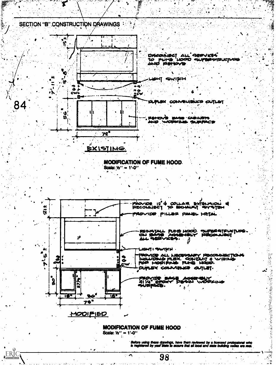
ti irl''''' 'I' . '.4 " ' 4 ',':, ' .' .:-'..... ... ,:..:::.:4,..:":'; /
SECTION 13",CQNSTRUCTI
IP .
01 #
o.
943
:/".
44 t
44,
4..441 41: ZI
CV4/4
1.
og
r
VI
1210044419GT 44101PV IOW140 MOM& 1.1000 fyreolervaucergivit
laprooN41.
1.4044.1 gwirs-4
O
4
0 4
comvati.itai? ourial. .
114144:044 10,066, cohaiiklerigib14.1. . N101P6111140 firtAspArcat
crt
re. .
I
MODIFICATION OF FUME HOOD.Scale: y ". 4/2 V.0"
12.'4 cou.Asa, spwremalo4 4laecouOlacT aro axmapum efordb-rete4
st---riolcaNiesolt swim.. He*.
1 * 41411940C
4961a%/1664
.........;...s.e>44-uwer 414/904'1201,41101P Falie.OWilfergb."
ad11101.MINMer Ft.1924. CC:9J PLAT *r00 MIDPIPINS. Pa.* ,ageln.
A .1:110PIAN catavieNIGIF 411.0TUtT
.friootr
*
''.----121,411riks-.136404114114MAait.syse../
04'
MODIFICATION OF FUME HOODScale: K" .1'4"
;
Mors using ems drawings, Inns Own inviewsd by Ocensed protwokate whoki iegbisred by yaretstol s saws tat boa/ and state bungling Naos so
`.

Construction Specifgations.Portable Science Stations (Multi-Use),General Requirements: Stations shall be prewiredand replumbed in'factOry: 410.
Altmealtanical/electricarservice fixtures andfitting's; shown or called for, to bemounted on orin conjunction with portable stations and ;
AuiPment, shallbe supplied complete.
Portable silence stations, shall be designed to (1,ptovide a convenient, barrier-free *work station.for*students confined to wheelchairs.
.
Unit shall be self-contained ancliortable tofacilitate storage or relocation as requited by'curriculum requiremeWs. Each unit shall bedouble-sided, one side for use lwblology labwork, the other side for chemistry or physics:kbactivities. Controls for cold water, air, andvacuum services shall be conveniently located onboth sides of table, as well as 110V duplex".electrical receptacles.
' . Portable science stations shall meet needs ofphysically handkapped.persont confined to awheelchair with regard to knee. clearance; forward
. and side reach, countertop height, location of 'services and controls**, and microscope shelflocation. r
.
I-Stations shall be 60 inches wide by 30 inches deep .
by .3.2kinches high, *V: inch.4 -./
,'s Standard Features: Countertops shall be one-piecei chemical resistant black fiberglass top withI 0. built-in raised edge on all four- sides to traint spillage. Tops shall be further recessed at area of
integrally molded sink. Built-in burette socketsshall allow use of optional appaistus rods.
Service cabinets shall be eqttipped with doisble .'doors to provide easy access to mechanical and .,
electrical systems which shall 12e prewired andpreplumbed.
.0.
I
Biology cabinets.sh411 consist of a pullsout shelf .
and a pull-out cupbotril Air storage of materials.
I
9PECTION "C" CONSTRUCTION SS CATIONS
Cupboards shall be Mounted on inechadad slide!for smooth opening and clozipg:with stopsprovided to prevent accidental removal. Aremovableote-tray shall be included and locatedwithin cupboards.
chemistry-physics cabinets shall consist of apull -out elf, a 4-inch deep drawer, and a12-inclideep pull-out cupboard for storage.Drawers and cup : shall be mounted on fullextension mechanical es with stops providedto prevent accidental removal.
Water'system shall consist of p two-gallonpressuriied supply container, a 2 gallon waste
, container, 1 lib hp pressure supply Pump withpressure regulathig switch, and a pciseneckfaucet with a serrated tip. Water Bow shall 'beactivated by push:bUtton =caviled solenoidvalve... 1
. Electrical systemk shall be completely preWiredand protected py a ground fault interrupterincluding a control panel on each side of tableapron with control ssvitcheetfor water and for'optibhal air and'vacuum systemt. Duplex 110 Vrecreptackbs shall be located on each side of thetable apron. Ehtire system shall be energized by a10400t electrical cord fitted with a standard .
grounding three-prong plug for connection tobuilding service outlet.
Note: The above spedficanon gs for the basic unit only.Specific equipment for special use (chemistry,dc.).roill have to be included Wise overall specifias
for this Piece 0 equipment.
Emergency Shotaer Unit and Eye Wdsh Stations: 'theexisting emergency shower units and eye washstations shill be changed to accommodate dtehandicapped in accordance with applicable codes.Extend and reroute the chain of the ernerilerIFY
to the level and area for wady openitionby the handicapped, if requiredrand providewith blade handles, if required.
The existing eye washltations shall be changed tothe elevation required to accommodate thehandicapped.

.
C.w..rrArg .14,04911Iftirt2.,4.1,4017, 0;;6'r! ."
. . .1
e ; V. :It i" k,' !,6 t, ,q,r,r10.Vialarilyn, i;
Cker Opening Measure: Items needed: a 3/4 inch di-muter wood dotiel tut to 32 inches; 12jnchlongstraight edge; and felt tip, thin line pen.
Cut the dowel to 32 buttes in length.: Make thefollowing markings with the felt tip pen on the.'dowel. Starting it one end: 1", 11/2"; 2", 3", 4". skipt o 16", 17", 18", 20", gildpio 27", Ws; 29", 30",31",32 ". You now have a useful tool to =MUM theclear width Of a door operdrtg, the height of a toiletseat, the distance of a grab bar from its supportingwall, orthe height from dtelloor to the underside ofa 'desk, lavatory, or work table.
Clear Opening of a,
4.. Measuring Tool
MEASURE
4 ;
. 1
*
CLEAR °PENNS MEASURE.,dikVATORY OR DESK MEASURE
.
. .
TOILET HEIGHT MEASURE
'Fo measure the clear opening of a door, the dowelshould be placed horizontally in the opening with
/ the door opened to 90° (see below). Panic openingdevices should not interfere with this clear openingmeasure, unless the device projects below 32inches.
4
0- - e
'If the dowel fits through the clear.opening, the door.meets the. minimum requirements. If the doweldoei not fit (refer to below), you can measure theclear opening by putting the 0" end of the doviel atthe .doqr surface with the other end as. close aspossible to. the door stop and jamb (see below). Thedimension from the door face to the stop can be teedby placing a straight edge as 'Shown...
Measuring Clear cpenIng If Dori
:,

Measuring from Door Flo e to the Stop Ar
b.
Ratnpe! 1:12.8we Requirerrient
Too stsp-suesix HIGH 81:66:,7.
..
itamp Slope Check: Itemeniecied112 lr.tch long bubble,,level; piece of wood 12 inches long by 1 inch high
; and the width of the bubble level; arid glue to jointhe level and the wood. . .
.
Cutthe piece of wood so that 1 inch on 12 iih remPake the level and glue it (as shown) to .
thr12 inch side of the block of wood. This devicecan now bused to determhie whether an existingramp meets or exceeds the 1 inch on 12'inch slopereqmiremealts.
sLopE fig
wefts CENTERED
Bubble Level and Wood Piece
S II
4'

, . ,1 .:r311 ,rro,:?,r..41P. ;1,11.-7.
"1; IF.V
S.
A
Door Openireg Pressure lofeasuri: Items heeded area 'the handle of die door open to approdmately 1 foc;t,spring scale (Measuring faun 0 to at least.10 tb.), andsome way of attaching this spring scale to the hen-dies of doors to be checked.
and at rest.. Raid the dosing force in pounds. .Theclosing force is ,approxitnatebi.6P percent of theforce needed to open the . Ost, timoMre,multiply this "closing ' by 1.6710 obtain the.'Opening force required fc the particular door beingchecked. Unless otherwise specified by applicable.
. ire- safety codes, an exterior door in the pathooftravel considered accessible 'shall not exceed 8
:poundt opening force. An inleilOrdoor shall have. a: =drawn .opening pressure.of 8 pounds. .
I.
lb. dosing force x i.67lb. opening rave.
The 60 percent efficiency factor is based bn ANSIA156.4 which requires that a door closer must be atleast 60 percent efficient.
tape Measure: A steel measuring tape of at least 6tThis device will measure the closing forces anted feet will be necessary to' obtain the other dirnentby the door closer foot. Attach the spring scale to .sions needed ferties survey.
.O
i
,
,
4-
.
I
to
A.
.1
ss
1.. 9. g.
,1...

.
. . .
. \ti:,!.
.
,
U
.
t .
.
100
.1
"S
r
S.
.
p
V
o.
°
1
.
1
Eleven. Dupont Circle.Suite 250
Washington, D.C. 20036
,
S
, , ,
.
*
-7*",/
103,*