Swinton Enterprise Telephony Project Adrian Hazeldine IT & Business Change Director.

The ETM® (Enterprise Telephony Management) System Technical Overview
Release 5.2
A product brief from SecureLogix Corporation

ETM® System Technical Overview 17 November 2006• 1
The ETM® (Enterprise Telephony Management) System Technical Overview
Introduction Enterprise security and voice telecommunication users have a challenge in securing and managing their voice infrastructure. Security threats include access to the internal data network through use of unauthorized modems; unauthorized access to the Internet via outbound modems; limited protection of authorized modems used for remote access; unauthorized access to voice systems; toll fraud; and other issues. Management challenges include those present in enterprises managing a dispersed network of proprietary PBXs, such as bandwidth management, monitoring trunk status and Quality of Service (QoS), call accounting, and Voice Over IP (VoIP) migration.
The ETM® System addresses each of these challenges. The ETM System includes expandable, managed "Appliances" that are deployed as a customer-premise device on voice trunks. These Appliances, which are controlled by remote Servers, support a number of existing security and management applications and allow expansion to support future applications. The ETM System is managed from a remote client that can be used to manage multiple Servers and hundreds of Appliances.
Figure 1 provides a high-level overview of these ETM System components.
Figure 1 - ETM® System Components

ETM® System Technical Overview 17 November 2006• 2
A high level description of the ETM System components is provided below:
• ETM® Platform Appliances—The ETM Platform Appliances are rack-mountable, in-line devices that contain one or more "Cards" and "Spans." On circuit-switched networks, they are deployed on trunks between the Central Office (CO) and the enterprise PBX; in the case of VoIP, the Appliances are deployed anywhere in the network where VoIP traffic passes. The ETM Platform Appliances continuously monitor all signaling and bearer traffic, and use an expandable policy engine to examine calls and take actions based upon user-defined rules. Monitoring all bearer/audio data allows the Span in the Appliance to accurately determine the call type, which is essential for policy execution. The Appliances include a fail-safe mode that leaves the circuits fully operational if the Appliance looses power for any reason. The Appliances are completely remotely managed and can be remotely upgraded with new software and applications. Several versions of the Appliance are available and described in a subsequent section.
• ETM® Server Appliances—ETM Server Appliances are rack-mountable devices typically deployed with ETM Platform Appliances. ETM Server Appliances are used to provide site-level server functions, such as additional authentication, large local storage, and processing for future applications. ETM Server Appliances offer the same remote management and upgrade capability as ETM Platform Appliances.
• ETM® Server software—The ETM Server software consists of processes that collect data from Appliances, maintain system configuration and policy data, store all call data in a database, generate reports, and provide an anchor point for the ETM Client. The ETM Server software consists of the ETM Management Server, an Oracle Relational Database Management System (RDBMS), and the ETM Report Server. These processes can run on one or multiple physical servers to allow the system to be configured to meet customer requirements.
• ETM® Client—The ETM System Console is the Graphical User Interface (GUI) used to monitor and control the ETM System. All security, management, and real-time visibility functions are available via this client. As shown in Figure 2, the ETM System Console provides a high-level view that allows access/login to multiple ETM Servers and common tools that operate across Servers. The ETM Client also allows access to the ETM System applications, including the Performance Manager, Directory Manager, and Usage Manager. The interfaces provided for the ETM System applications are described and illustrated in a subsequent section.
Figure 2 - ETM® System Console
• ETM® Web Portal—The ETM Web Portal provides a secure means of allowing users to access features of the ETM System without installing the client software. The ETM Web portal provides web-based access to the ETM System reporting features and the ETM Call Recording capabilities. Users can schedule reports, view generated reports, and listen to recorded calls, all via a secure web interface.
The ETM System is expandable and supports various security and management applications. Several applications are bundled; other optional applications are available now, and more optional applications are planned for future release. Most applications are software upgrades or involve simple hardware expansions, such as the addition of a daughter Card or use of an ETM Server Appliance.

ETM® System Technical Overview 17 November 2006• 3
The ETM System is fully distributed, with the ETM Server capable of managing one to many Appliances located locally or remotely. One client can locally or remotely manage one or multiple instances of the Server. All policy, configuration, and software upgrades can be downloaded from the Server to local and remote Appliances. Figure 3 is an example in which one Server is used to provide management of local and regional Appliances, and each region has some number of Appliances and possibly a local client.
Figure 3 - Illustration of Distributed Architecture
For most enterprises, a LAN/WAN is used to connect the components of the ETM System. Each link between components of the ETM System can be protected with strong authentication and Triple DES (3DES) encryption.

ETM® System Technical Overview 17 November 2006• 4
Voice Over IP (VoIP) Support The ETM® System continues to support circuit-switched trunk interfaces, which account for more than 99% of the public voice access for enterprises. Because IP Telephony is rapidly gaining acceptance in the enterprise market, three types of ETM Platform Appliances provide both circuit-switched and IP telephony interfaces. For VoIP networks, the ETM System has been updated to include support for the Session Initiation Protocol (SIP) and H.323 VoIP protocols.
Each ETM Application (except Call Recording) allows unified security, management, and reporting, independent of the underlying transport. VoIP support is integrated throughout the ETM System to ensure that enterprises can transition from a circuit-switched to a VoIP network without compromising security.
Figure 4 illustrates the ETM System’s management and security applications' support for both circuit-switched and IP trunks.
Figure 4 -Firewall Policy defined to protect both circuit-switched and VoIP trunks

ETM® System Technical Overview 17 November 2006• 5
ETM® System Application Suite The ETM® System provides several bundled and optional security and management applications. The available applications in version 5.2 include:
• Performance Manager—Provides real-time visibility into trunk health and status, VoIP QoS alerts, and secure, remote management of distributed telecom resources.
• Directory Manager—Used to manage the directory of phone numbers and VoIP Uniform Resource Identifiers (URIs) accessible to all of the ETM Applications.
• Voice Firewall—Provides real-time detection and blocking of TDM, analog, and VoIP attacks over phone lines while controlling enterprise voice network access and usage.
o AAA Services for the Voice Firewall—Optional add-on to the Voice Firewall; provides strong authentication for modem access.
• Voice IPS—Provides for real-time call-pattern anomaly detection and prevention of toll fraud, war dialing, and service abuse/misuse for both circuit-switched and VoIP networks.
• Call Recorder—Provides policy-based call recording of targeted calls of interest on TDM and analog lines. (Not on VoIP.)
• Usage Manager—Provides enterprise-wide call-accounting reporting.
Additional applications are being developed for future releases. The following sections describe each of the currently available applications in more detail.
The Performance Manager The ETM® Performance Manager provides unified, real-time, enterprise-wide visibility into the performance of all enterprise voice services, including the health and status of TDM/analog calls and the circuit-switched infrastructure, and the QoS/performance of VoIP calls on the data network.
The Performance Manager provides PBX- and media-independent monitoring and a consolidated, comprehensive view of voice service performance across the enterprise. It provides a consolidated, dashboard view of any hybrid network mix of multiple-vendor systems, trunking protocols, and TDM/analog/VoIP media types found in today’s converging networks. The real-time console provides up-to-the-minute alerting on QoS events, changes in operational status of the network, and violations of established usage policies. Additional console, email, or SNMP trap notifications can be assigned to any monitored event.
Some of the key features the Performance Manager provides include:
• Centralized, Real-Time Health and Status—Real-time, enterprise-wide, single-view health-and-status monitoring of TDM & VoIP signaling error conditions on all monitored circuits.
• Real-time Notification of Availability and QoS—A wide variety of telecom events can be configured to generate real-time notifications when line errors impact service quality or availability.
• Call Monitor Real-Time Call Display with Call Termination—The Call Monitor displays active call information with call-type data on all inbound and outbound calls. The Call Monitor can be configured to view an individual channel, Span, group of Spans, or all Spans enterprise-wide. Suspect calls can be manually terminated in real time.
• VoIP Codec Configuration and Monitoring—The Codec Configuration GUI includes more than twenty predefined, ITU-standard codecs to allow you to establish QoS thresholds that include values for packet loss, delay, and jitter.

ETM® System Technical Overview 17 November 2006• 6
• PRI Caller ID Masking and Call Redirection—Allows granular, source-dependent generation of the Calling Party Number (CPN) to be reported for outbound calls and allows inbound and outbound redirection of calls.
• Logical Span Groups—Fully logical Span groups allow for independent grouping of Spans (regardless of PBX configuration) to support trunk groups and distribute security and usage policies. Spans from different ETM Appliances and PBXs can be grouped and managed as a unit.
• Troubleshooting Tools—Alarm icons alert to circuit errors and an easy-access health-and-status display provides details. Distinct color-coded icons, logical grouping of functions, and automatic diagnostic log filtering allow you to quickly isolate potential line errors, immediately determine the severity of errors, and gain vital troubleshooting information.
• Visibility of Telecom Signaling—Allows verification of purchased services such as DID (Direct Inward Dial) and DNIS (Dialed Number Identification Service) and operation of automatic dialers in call center environments.
• Command-Line Span/Trunk Diagnostics—Command-line interface provides quick access to Span/trunk diagnostics to aid in faster resolution of circuit issues with the service provider.
The Performance Manager provides the interface to the Voice Firewall, Voice IPS, and Call Recorder applications; CPN masking, call redirection, and billing plans; and tools for call monitoring, log review, and diagnostic analysis. Figure 5 contains several Performance Manager screens, including the graphical tree representation of the ETM System Policies, Span Groups, telco configuration and monitoring, and ETM Platform configuration and monitoring. Additional “drill down” features are available from the tree pane and main menu for review of the status of Cards/Spans, circuits, and active calls.
Figure 5 - Performance Manager

ETM® System Technical Overview 17 November 2006• 7
The Directory Manager The Directory Manager is used to manage the directory of phone numbers and VoIP Uniform Resource Identifiers (URIs) accessible to all of the ETM Applications. These "Directory Manager objects" and their associated information are used in policies and reports and to annotate real-time notifications (such as for 911 calls), real-time display of call data, log data display, policy generation, and reporting.
The Directory Manager acts much like a phone book by providing a linkage between a phone number and/or URI and a real world entity. For example, the Directory Manager might allow a “listing” for 555-1234 or [email protected] to be associated with “John Doe in Marketing that works for Mary Smith located Building 2 at the San Antonio site.”
The Directory Manager is typically populated from an existing enterprise database. The Directory Manager provides a powerful import and reconciliation tool that allows the Directory Manager to stay in sync with the enterprise LDAP or similar repository.
The Directory Manager allows you to associate the following data elements with each Directory Listing:
• Phone Number—Phone number of the station within the enterprise or the phone number for external entities, such as ISPs, clients, vendors, and so on.
• URI—Allows the association of up to 5 different URIs with each Listing, whether the Listing is internal or external to the enterprise.
• Name—First and last name associated with the phone number. For example, "3rd floor fax machine" or "John Doe."
• Extension Type—Characterizes the phone number as any combination of voice, fax, modem, data, or STU call types.
• Department—Can be used to produce Department-level cost allocation reports
• Authorization Code—Can be matched against authorization codes in the PBX provided by SMDR to track outgoing long distance.
• Mail Code, Location, Site, Email, Comment—Simple text fields to specify location-specific information that can be used, for example, in the reporting of the location in 911 alerts so that building security personnel can direct emergency responders to the exact location of the incident.
• Custom Fields—3 custom fields are provided that you can rename and define as necessary. In Figure 6, the first custom field is named “Manager” to allow the association of the manager of the department with each Listing.

ETM® System Technical Overview 17 November 2006• 8
Figure 6 - Directory Manager
In addition to the individual Listings, the Directory Manager provides several ways to group and aggregate or select subsets of Listings for policy construction and usage reporting. These include:
• Dynamic Filters—The set of Listings that match a selection criterion, for example, all Listings in the Marketing Department. As Listings are added or removed from the Directory Manager, the Dynamic Filters are automatically updated to keep security policy and usage reports up to date.
• Ranges—A range of phone numbers, such as a block of extensions or entire exchanges.
• Wildcards—Match selected portions of a URI or phone number (country code, country and area code, exchange, extension) rather than the complete URI or all digits of a phone number.
• Groups—Static collections of Listings, Ranges, or Wildcards; they may also contain other groups.

ETM® System Technical Overview 17 November 2006• 9
Voice Firewall The ETM® System Voice Firewall unifies the security of telephony traffic and infrastructure across hybrid TDM and VoIP networks. The Voice Firewall provides application-layer security to real-time media, and works side-by-side with your data firewall to help complete the security of your corporate electronic perimeter.
The Voice Firewall allows you to define rules-based policies that provide fine-grained control over which TDM/analog or VoIP calls are allowed or terminated, and which tracking events occur for each call. This policy allows an enterprise to enforce its telephony usage policies. The Voice Firewall monitors phone lines to prevent attacks against data networks and telephony systems through modems and allows control of unauthorized employee Internet usage via outbound modems. The Voice Firewall policy also allows enterprise-wide control of other types of calls, including fax calls, long distance and international calls, video usage, and use of secure phones (STU-IIIs).
The Voice Firewall allows an enterprise to control toll fraud and other forms of phone line misuse and abuse. It also filters VoIP traffic with wire-speed inspection of call signaling and in-depth monitoring of application behavior to detect and prevent VoIP application layer threats. These include signaling and media-based Denial of Service (DoS) and malformed signaling attacks targeting VoIP systems.
Figure 7 - Voice Firewall Policy
As shown in Figure 7, a policy contains some number of user-defined rules. Rules are executed for every call monitored by the ETM Spans on which the policy is installed. Call parameters are compared to the criteria specified in each rule in numerical sequence. If a match occurs, the Span performs the specified action (allow or terminate) and the ETM Server executes the specified track (log, generate a screen alert, send an email, and/or send an SNMP trap), if any.

ETM® System Technical Overview 17 November 2006• 10
The criteria available in each rule includes:
• Call Direction—Inbound, Outbound, or Any (all calls).
• Source number—One or more Directory Manager objects (Listings, Filters, Groups, Ranges, Wildcards), Subnets, or AAA Service Users. It is also possible to specify “Caller ID Restricted,” to take special action if a caller intentionally blocks the source number, or "No Source" for any other case in which the source is unavailable beside CIDR.
• Destination number—Same as Source number above, with the exception of Caller ID Restricted, No Source, and AAA Service Users.
• Call Type—The actual type of the call, based on analysis of the audio data. Can be voice, fax, modem, modem energy, data, video, STU-III, busy, unanswered, undetermined, or Any.
• Time—The date and time range when the rule applies, or Any. You can specify blocks of times/dates, such as weekends or after business hours.
• Duration—Length of the call measured in hours and minutes.
• Attributes—VoIP call attributes, including unknown Codec, excessive media rate, media timeout, signaling anomaly, or none.
• Action—Allow or Terminate calls that trigger the rule.
• Track—Track actions, including log, email, SNMP trap, real-time alert, or none.
• Install On—Used to specify one or more specific Span Groups on which to install the rule, or all Span Groups assigned to the Policy.
For more information about how these parameters are determined and used for policy, refer to the subsequent section describing the operation of the ETM Platform Appliance.
You can build any number of policies. For example, you can develop specific policies for trunk groups or sites, or can build one large policy in which some rules apply to different trunk groups/sites. Multiple policies can be pre-built and installed immediately as security conditions change. You can also hide, enable, and disable rules in the policies.
Voice Intrusion Prevention System The ETM® Voice IPS (Intrusion Prevention System) application provides real-time detection and prevention of threatening or abusive call patterns across your TDM/analog and VoIP infrastructure, including toll fraud, VoIP spam, modem war dialing attacks, hacker access, bandwidth or service abuse, and other pattern-based attacks in the call signaling and media streams.
Voice IPS policies allow real-time thresholds to be established for a variety of service types—such as long distance or international calls—and can be triggered by call count, call minute accumulation, or actual accumulated toll charges. Voice IPS policies can terminate malicious or abusive call activity in real-time, limiting an organization’s financial exposure to toll fraud. The application also includes a real-time viewer, which displays current call counts, current accumulated call minutes, or current accumulated toll charges, based upon configured policy rules.
You can use Usage Manager reports to determine historical baselines and expected call activity and expenses so you can set appropriate call pattern thresholds. Historical baselines can be calculated using min, max, mean, and standard deviation. Voice IPS call count, call duration, and call cost accumulations are recorded in the database, providing a historical summary of each rule interval. These rule summaries can be used to generate historical reports very quickly without having to reprocess every call record.
Key benefits/features of the Voice IPS include:
• Detect, alert, and prevent potential toll fraud or service abuse in real-time for all inbound or outbound call traffic regardless of media type (TDM, analog, or VoIP).

ETM® System Technical Overview 17 November 2006• 11
• Monitor trunking infrastructure for operational anomalies such as excessive busy signals, excessive unanswered calls, or a lack of call traffic on inbound or outbound call center trunks.
• Define important usage metrics for real-time and historical reporting.
• Rule-Based Policies are constructed of individual rules through an easy-to-use graphical user interface similar to the Voice Firewall. Polices can be grouped and installed on any combination of Spans or Span groups.
• Enterprise-Wide Usage Policy Enforcement—Rule-based usage restrictions and call monitoring allow you to secure and control how many inbound or outbound calls are allowed, terminated, or alerted based on call counts, accumulated call minutes, or accumulated call charges (tolls).
• Granular Service Monitoring—Policies can alert and control call activity based on service types, (long distance, international, etc.) and/or any combination of policy fields (source and destination, call direction, duration, and time of day).
• Real-time Viewer Tool displays current call counts, accumulated call minutes, or accumulated toll charges for any of the configured thresholds within each rule, offering an up-to-the-minute view.
• Flexible Termination Actions—Terminate rules can be configured to terminate all calls that match a rule that has exceeded its threshold, or only future calls that match the rule once the threshold has been exceeded.
• Real-Time Alerts for rule breaches—Any IPS policy can be configured to fire a real-time event alert via console message, email and /or SNMP trap when a rule has exceeded its threshold.
• Flexible Rule Intervals—Noncontiguous rule intervals can be defined that span a variety of time frames: weekends, weekday, after hours, business hours, per day, per week, etc. As shown in Figure 8, the intervals can be further subdivided per hour for more granular monitoring. You can use these intervals in Voice IPS policies and Usage Manager reports when determining historical baselines.
Figure 8 - Hourly Intervals defined in the Interval Properties dialog box

ETM® System Technical Overview 17 November 2006• 12
Figure 9 demonstrates how a Voice IPS policy can be structured to monitor a variety of telecom conditions within the enterprise.
Figure 9 - Voice IPS Policy
Figure 10 demonstrates how the summarized results for a Voice IPS rule can be plotted with standard deviations to facilitate threshold selection.
Figure 10 - Voice IPS Report

ETM® System Technical Overview 17 November 2006• 13
AAA Services for Voice Firewall AAA Services for the Voice Firewall is an optional ETM® System application that augments the Voice Firewall. AAA Services offers centralized authentication, authorization, and accounting of modem users within the enterprise. AAA supports inbound/outbound users and provides an authentication Appliance, which prompts the remote caller for a valid user ID, PIN, and destination phone number prior to allowing any connection attempt to authorized modems or controlled services.
AAA Services requires deployment of an ETM Server Appliance. This Appliance provides 1 to 4 modems, that operate only in voice mode, to provide the Interactive Voice Response (IVR) system used to authenticate a user. The modems in the AAA Server Appliance will normally be connected to the PBX via an analog line. Figure 11 illustrates this configuration.
AAA Services are supported using a two-call process that includes an initial call to the Server Appliance, followed by the call to the destination phone number. In the initial call to the Sever Appliance, the remote user is presented with a configurable series of prompts for a user ID, PIN code, and the desired destination phone number of the authorized modem.
The Server Appliance accepts the remote user’s input and authenticates it against a locally stored database of authorized AAA Services Users. After the Server Appliance authenticates the user's PIN code, the Server Appliance authorizes the second call to the specified destination number.
Figure 11 - Illustration of AAA Services
Once the initial call has been authenticated, the Server Appliance sends an authorization token to the ETM Server and to the ETM Spans that control access to the requested destination number. The token has a configurable time to live (TTL) that defaults to five minutes, opening a single session through the Voice Firewall to allow the authorized user’s call access to the destination number.
For more information on AAA Services, please refer to the “AAA Services for the Voice Firewall Technical Discussion.”

ETM® System Technical Overview 17 November 2006• 14
The Usage Manager The ETM® System stores information in a database for every call throughout the enterprise that passes through the ETM Platform Appliances. These call records include CDR, call accounting, call type, VoIP CODEC, resource utilization, trunk status, and other information sensed by the Appliances. This database is ideal for the generation of enterprise-wide security and management reports. The Usage Manager, shown in Figure 12, provides an extensive set of more than fifty predefined report templates and a powerful, integrated report editor that you can use to modify existing or define new reports. The Usage Manager provides access to more than seventy-five data fields drawn from the CDR, trunking performance, QoS, and network security events logged by the ETM Appliances. All of this information can be formatted, grouped, charted, and filtered in a variety of configurations, offering exceptional flexibility in reports design and analysis.
Fully customizable billing plans and user/extension Directory support allow for highly accurate cost allocation or bill verification auditing and call accounting. The Usage Manager includes North American and International location databases for detailed identification of called/calling party country and city-state information. Regular updates to the location databases are available from the SecureLogix Support Web site. Figure 13 contains a sample report showing the accumulated International call minutes and the calling party’s location information.
Reports can be previewed, printed, and saved to a variety of formats, including Portable Document Format (PDF), PostScript (S), Hypertext Markup Language (HTML), Rich-Text Format (RTF), and Comma-Separated Values (CSV). The Usage Manager provides a flexible scheduling tool that allows reports to run automatically on an hourly, daily, weekly, or monthly basis. These "Scheduled Reports" are stored in the database for later viewing, distributed via email, saved in the Usage Manager tree, or stored on a network share for enterprise wide access.
Figure 12 - Usage Manager

ETM® System Technical Overview 17 November 2006• 15
Figure 13 - Sample Detailed Usage Manager Report with Location Data
Call Recorder The ETM® Call Recorder provides policy-based capture of the audio and data content of calls. For example, you can:
• Record all inbound calls for quality assurance and security monitoring.
• Record calls on selected fax, modem, or STU-III lines to verify that classified or sensitive information is not being disclosed.
• Record calls from/to customer support lines, to provide an audit trail.
• Capture threatening or harassing calls to your staff for investigation.
• Ensure that calls to protected extensions are never recorded.
Since the recording is policy-based, no user intervention is needed to begin recording—recording begins automatically at the start of a call for the lines you specify. You can also define a list of protected extensions, such as pharmacy lines, to which calls are never to be recorded.
The Call Recorder uses the same policy-based call selection paradigm and many of the same data fields as the Voice Firewall and Voice IPS to select the calls of interest. A Call Recorder policy uses the following call attributes to select the calls to record:
• Call direction (inbound, outbound)
• Source and Destination
• Call Type
• Time of Day

ETM® System Technical Overview 17 November 2006• 16
In addition to selecting the calls of interest, the Call Recorder policy allows a priority to be assigned to each recording. The Priority setting governs the order in which calls are transferred from the CRC to the Collection Server, if one is used, and for deleting recordings when disk space limits are reached. It does not affect whether calls are recorded. Figure 14 demonstrates a sample policy.
Figure 14 - Call Recorder Policy
The Call Recorder uses a distributed architecture, illustrated in Figure 15, that consists of:
• The ETM Server to manage the Recording Spans and the Call Recording Cache (CRC) applications, and provide recordings to the Web Server for access via the Web Portal.
• The Call Recorder application. Installed on the ETM Server and accessed via the Performance Manager; used to define, manage, and install Recording Policies; view Health & Status, and specify the .wav greeting file to be played to callers on Analog recording Spans.
• One or more recording-enabled ETM Spans to transfer calls to a CRC application, where they are recorded in real time. All Span types except VoIP can be recording-enabled via software. Analog Spans in the ETM 1012/1024 Appliances can optionally play an announcement at the start of the call. Digital Spans rely on the announcement capability of the PBX.
• A Call Recording Cache (CRC) application to which the recording Spans transfer information to be recorded. The CRC application can run on the 1024, 1090, or 1060 Appliance.
• The ETM Web Portal to locate and access call recordings stored on the CRC.
• (Optional) A Collection Server for offsite storage of call recordings. The Collection Server is a Windows application that runs on Windows 2000 or 2003. When a Collection Server is used, CRC applications send the audio files and associated call data for the recorded calls at user-defined intervals to the Collection Server for storage. The Collection Server runs a call record filter to convert each recorded call’s audio file and call data from its received format to a final format that is compatible with third-party playback and analysis tools such as TSAP and Windows Media Player.
Figure 15 - ETM® Call Recorder Architecture

ETM® System Technical Overview 17 November 2006• 17
ETM® Appliance Technical Discussion The ETM® Platform Appliances are custom devices that allow monitoring of telecommunications data and enforcement of a user-defined policy. All Appliances are 19” rack mountable devices in 1u and 2u heights. Different types of Appliances exist for monitoring various telecommunications circuits.
The following versions of the Appliance are available:
• ETM® 1000-Series Hybrid Appliance—The ETM-1000 Hybrid Platform Appliances are 1u devices that simultaneously support 1 VoIP Span and either 1 DS1 or up to 24 analog trunks. All Hybrid Appliances provide a SecureLogix proprietary Fail-Safe VoIP Span in addition to a traditional TDM or analog Span. The TDM DS1 Span supports T1 and E1 line rates and either CAS or PRI signaling. The line rate and signaling type are software selectable. Available versions include:
o 1012—Analog; 12 channels + 1 VoIP Span
o 1024—Analog; 24 channels + 1 VoIP Span
o 1024CR—Analog; 24 channels + 1 VoIP Span + Call Recorder Cache
o 1090—1 DS1 Span + 1 VoIP Span
o 1090CR—1 DS1 Span + 1 VoIP Span + Call Recorder Cache
• ETM® 2100-Series Platform Appliance—The ETM 2100-Series Platform Appliance is a 1u device with 1 compact PCI (cPCI) Card set that supports 1 to 4 DS1s. This Card set includes a Digital Trunk Interface that provides the T1 or E1 (PRI, CAS, or SS7) interfaces, relays, and line interface units. The Card set also includes a controller that provides the processors, memory, and other storage. The same chassis and Card set is used for T1 CAS, T1 PRI, E1 PRI, E1 CAS, and SS7 Spans. Each SS7 Bearer Span provides support for up to 2 fully associated SS7 signaling links, allowing SS7 signaling links and bearers to be managed on the same Card. The software supports mixing T1 or E1 circuit types on one Card set. The Card set supports addition of PMCs that can be added to support optional applications. The available version includes:
o 2100—1 to 4 T1 or E1 (PRI, CAS, or SS7) Spans

ETM® System Technical Overview 17 November 2006• 18
• ETM® 3200-Series Platform Appliance—The ETM 3200-Series Platform Appliance is a 2u device with 1 to 4 cPCI Card sets that each support 1 to 4 DS1s. The total capacity of this device is 16 DS1s that can be any combination of T1 Spans (PRI, CAS, and SS7) or E1 Spans (PRI, CAS, and SS7). A Card set can also be used for one dedicated SS7 signaling link, or can support SS7 bearer Spans with fully associated signaling links. The chassis is cPCI and supports hot swapping controller Cards, power supplies, and fans. The hot swap capability enables any controller Card to be removed and replaced without impacting the operation of other Cards. During hot swapping, the transition module is not affected, so the Spans continue to allow traffic. The power supplies are N+1 redundant and the device can operate with a single power supply. Both AC and DC power supplies are available. The available versions include:
o 3200AC—1 to 16 T1 or E1 Spans (CAS, PRI, or SS7)
o 3200DC—1 to 16 T1 or E1 Spans (CAS, PRI, or SS7)
ETM Server Appliances are used for Server functions, such as the Call Recorder and AAA Services:
• ETM® 1060 Call Recorder Cache (CRC) Appliance—The ETM 1060 Call Recorder Cache Appliance is used to support the Call Recorder add-on application. The 1060 CRC records and stores calls from multiple Recording Spans. This Appliance has no other Spans and cannot monitor calls or execute a Recording Policy. It simply stores calls and optionally transfers them to a Collection Server. Each 1060 Call Recorder Cache supports:
o 32 voice Spans (3200-, 2100-, or 1000-Series Hybrid)
o Up to 120 simultaneous recordings
o 2,000 hours of recording storage
o Compression and encryption to the Collection Server
• ETM® 1050 AAA Server Appliance—The ETM AAA Server Appliance is used to host the AAA Services add-on application. The ETM AAA Server Appliance is a 1u device that supports 1 to 4 modems used to provide the Interactive Voice Response (IVR) used for authentication.
ETM® System Technical Overview 17 November 2006• 19
Telecommunications Circuit Type Support The following types of circuits and signaling are supported:
• VoIP—Supports SIP and H.323 IP signaling. VoIP support requires the SecureLogix proprietary Ethernet Fail Safe interface Card that is currently only available on the ETM 1000-Series Hybrid Appliances.
• Analog—Supports loop start, ground start, and reverse battery loop start trunks. Supports FXS and FXO. Analog support is available on the ETM 1000-Series Hybrid Appliances.
• T1 CAS—Supports Super Frame and Extended Super Frame framing formats. Supports Alternate Mark Inversion and Bipolar 8 Zero Substitution line coding. Supports ground start, loop start, wink start, immediate start, and asymmetrical signaling. Supports various cable lengths (line build outs). Supports DTMF and MF digit detection. For fractional T1s, the non-voice channels can be ignored. T1 CAS support is available for the ETM 1090, 2100, and 3200 digital Appliances.
• E1 CAS—Supports CAS signaling on a 30-channel E1 Span. Supports the CRC4 Multiframe and Non-CRC4 Multiframe framing formats. Supports Alternate Mark Inversion and High Density Bipolar Order 3 line coding. Supports the R1 signaling type only. Supports MF and DTMF digit detection. E1 CAS support is available for the ETM 1090, 2100, and 3200 digital Appliances. .
• T1 PRI—Supports a 24-channel T1 Span using PRI signaling (often referred to as ISDN PRI). Supports the DMS100, ATT 5ESS, ATT 4ESS, and NI-2 variants. Supports Non-Facility Associated Signaling (NFAS). NFAS allows multiple PRI Spans to be controlled from a single D channel. Supports use of backup D channels. T1 PRI support is available for the ETM 1090, 2100, and 3200 digital Appliances.
• E1 PRI—Supports a 30-channel E1 Span using European variants of ISDN PRI. Supports the NET5 and QSIG protocol variants. Certification testing was only performed against the NET5 protocol version, as customer demand for the other protocol variants is limited due to the widespread standardization on NET5. Support for DASS2 and DPNSS is also provided. E1 PRI support is available for the ETM 1090, 2100, and 3200 digital Appliances.
• T1/E1 SS7—Both fully associated and dedicated SS7 signaling are supported.
- For fully associated SS7 signaling Links, each SS7 Bearer Span provides support for up to two fully associated SS7 signaling links, allowing SS7 signaling links and bearers to be managed on the same Card.
- For dedicated SS7 Cards, the cPCI Card sets support 1 to 4 ANSI SS7 signaling links carried over a single DS1. The signaling links may be 56Kbps or 64Kbps (but must all be the same). This Card set is only packaged in the ETM 3200-Series Appliance. Note that in this configuration, the Card set cannot process bearer Spans, but can communicate signaling information to other Card sets managing the bearer Spans.

ETM® System Technical Overview 17 November 2006• 20
ETM® Platform Appliance Interface Connections Each of the ETM® Platform Appliances provides interfaces for the various telecommunications circuits and standard interfaces for network access, power, and so on.
Figure 16 illustrates the interfaces provided on front of the ETM 1000-Series Hybrid Appliances. These interfaces are common to the 1012, 1024, and 1090 models.
Figure 16 - ETM® 1012/1024/1090 Series Hybrid Appliance Front Connections
Figure 17 illustrates the analog interfaces provided on the back of the ETM 1012- and 1024-Series Hybrid Appliances.
Figure 17 - ETM® 1012 and 1024 Series Hybrid Appliance Rear Analog Connections
Figure 18 illustrates the digital DS1 interfaces provided on the back of the ETM 1090-Series Hybrid Appliance.
Figure 18 - ETM® 1090 Hybrid Appliance Rear Digital Trunk Connections
ETM® System Technical Overview 17 November 2006• 21
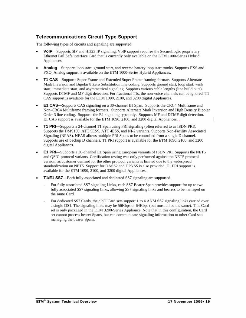
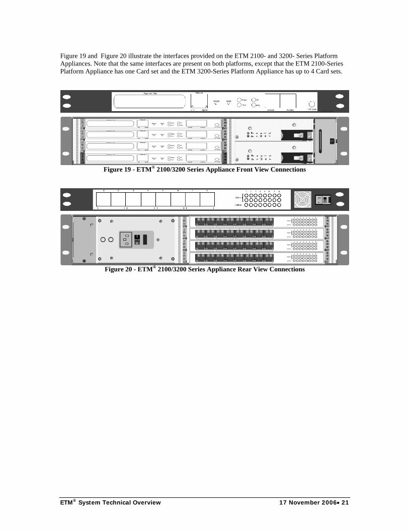
Figure 19 and Figure 20 illustrate the interfaces provided on the ETM 2100- and 3200- Series Platform Appliances. Note that the same interfaces are present on both platforms, except that the ETM 2100-Series Platform Appliance has one Card set and the ETM 3200-Series Platform Appliance has up to 4 Card sets.
Figure 19 - ETM® 2100/3200 Series Appliance Front View Connections
Figure 20 - ETM® 2100/3200 Series Appliance Rear View Connections

ETM® System Technical Overview 17 November 2006• 22
Item Appliance Description
10/100 Base-T connector
All An RJ-45 connection for attaching the Appliance to an Ethernet 10/100 network.
Console All The serial port for a direct Appliance command line connection.
Auxiliary All The serial port for connecting an SMDR/CDR Provider Appliance to the SMDR port on a PBX.
Power LED All Power indicator.
Status LEDs All Progress indicators for Appliance startup and status information during Appliance operation.
Service All A switch used to place the Appliance in Failsafe Mode.
CO and PBX alarm LEDs
All DS1 Indicates alarm conditions on the monitored lines.
To CO All DS1 An RJ-48C connector used to connect the Span from the CO to the Appliance.
To PBX All DS1 An RJ-48C connector used to connect the Span from the Appliance to the PBX.
Hot Swap LED 3200 Hot swap in progress.
Ethernet 0 Ethernet 1
1000 Hybrid Two RJ-45 connectors for attaching the Appliance to Ethernet 10/100 network with VoIP signaling.
Link 0 and 1 1000 Hybrid Indicates the corresponding VoIP Ethernet interface link has been established.
Speed 0 and 1 1000 Hybrid Indicates the speed (10/100) of the corresponding VoIP Ethernet interface.
ETM® Server Appliance Interface Connections Figure 21 illustrates the interfaces provided on front of the ETM 1060 Call Recorder Cache Appliance.
Figure 21 - ETM® 1060 Call Recorder Cache Appliance Front Connections
The AAA Server Appliance provides interfaces typical for a Server platform. Figure 22 illustrates the interfaces provided on the AAA Server Appliance.
Figure 22 - AAA Server Appliance Connections

ETM® System Technical Overview 17 November 2006• 23
ETM® Appliance Design and Technical Specifications The ETM® Platform Appliances consist of custom hardware and software. The Platform Appliances have the following processors and storage capacities:
• ETM 1000-Series Hybrid Appliance:
o Motorola 8241 CPU
o 4 Texas Instruments (TI) TMS320VC5510 DSPs
o 64 megabytes (MB) of RAM
o Non-volatile storage (used for policies, configuration, and logs): 64 MB minimum (ETM 1012/1024/1090) 4 GB minimum (ETM 1024-CR) 8 GB minimum (ETM 1090-CR)
• ETM 2100- and 3200-Series Appliance:
o Motorola 8240/8245 CPU
o 10 Texas Instruments (TI) TMS320VC5510 DSPs
o 64 MB of RAM
o 128K of Non-Volatile RAM (NVRAM) (used for recovery)
o 64 MB minimum of non-volatile storage (used for policies, configuration, and logs)
The ETM Server Appliances include off-the-shelf systems used for Server functions, such as AAA Services, and SecureLogix-designed Servers such as the 1060 Call Recorder Cache.
The 1060 Call Recorder Cache Appliance has the following processor and storage capacity:
• ETM 1060 Call Recorder Cache Appliance:
o Motorola 8241 CPU
o 6 Texas Instruments (TI) TMS320VC5510 DSPs
o 64 MB of RAM
o 120 gigabytes (GB) of hard disk storage (used for recorded calls, configuration, and logs)
The off-the-shelf AAA Appliances have the following processor and storage capacity:
• AAA Server Appliance:
o 1 Ghz Celeron CPU
o 128 MB of RAM
o 128 MB of non-volatile storage (used for AAA database, configuration, and logs)

ETM® System Technical Overview 17 November 2006• 24
All ETM Appliances use a tailored version of Linux, based upon the 2.6 kernel and a custom version of BusyBox. The version used includes the basic kernel and networking support. The approximate size of the entire Linux disk footprint is 2.5 megabytes. Networking support includes TCP/IP sockets and required network services (ICMP and ARP), which are used to communicate with the ETM Server and other Appliances (for NFAS and SS7). A custom and very restricted version of Telnet is provided as an optional service and can be used to directly manage the Appliances. (For security reasons, this is disabled by default). The Appliance uses the “IP Tables” capability provided by Linux to discard any IP packet that is received from a host with which the Appliance is not programmed to communicate.
All Appliance software is fully upgradeable. The operating system and application software, boot software, DSP software (if applicable), and Field Programmable Gate Array (FPGA)/Programmable Logic Device (PLD) software (if applicable) are upgradeable via the ETM Server and ETM Client.
The ETM 1000-Series Hybrid Appliances are designed for installation on IP segments that carry VoIP call signaling and media. These Appliances contain a set of programmable relays between the VoIP Ethernet interfaces. In a powered-off state, the default configuration of the relays allows Ethernet traffic to pass through the Appliance. Once power is applied and the VoIP software is initialized, the relays are energized, and the VoIP Span is placed in the flow of the IP packets. If power is removed or the VoIP Span taken offline, the relays are closed, and the Ethernet traffic passes through the Appliance as if the Appliance was not present. In the event the Appliance is performing Network Address Translation (NAT) of IP addresses, the relays can be configured to remain open, even when the Appliance is powered off. Figure 23 illustrates this signaling path.
Figure 23 - VoIP Signaling Path Design
The ETM 1012 and 1024 Hybrid Appliances are designed for analog trunks. Within these Appliances, relays are used to maintain a continuous circuit during normal operation and during power loss. The relays are only engaged for a few seconds when the policy directs termination of a call. During normal operation—even if power is removed—there is a continuous circuit through the Appliance. This Appliance adds no latency to the signal. This Appliance can be deployed on analog circuits that connect directly to stations (typically remote access Servers or fax machines). However, this Appliance does not support vendor-proprietary digital station circuits.

ETM® System Technical Overview 17 November 2006• 25
The ETM 1090-, 2100-, and 3200 Platform Appliances should be installed between a Channel Service Unit (CSU) and the PBX. While these Appliances provide surge protection, the CSU is typically required for loop-back testing at the edge of the demarc by the local phone service provider. These Appliances can also be deployed outside an integral CSU if an equivalent Network Interface Unit (NIU), such as a “Smart Jack,” is provided. If the Appliance is deployed in a location where loop back codes/tests are sent, it detects this condition and transparently passes through the loop back codes/test. The Appliance does not attempt to process any signaling or audio on the circuits during loop-back testing.
For all digital TDM interfaces, relays are present and remain disengaged when the power is off, the Appliance is booting, or if the Appliance is taken off-line. In the disengaged state, there is a continuous circuit through the Appliance and absolutely no latency is added to the signal. The failsafe circuitry does add a small amount of resistance to the circuit, so the configuration should always be tested when circuit values such as signal strength or cable length are changed.
When the digital TDM Appliance is booted and ready to begin processing, the digital interface engages relays and routes the signal through several components. The signal is terminated by a Line Interface Unit (LIU), provided to the digital Appliance for processing, and regenerated by a second LIU. If power is interrupted, the digital Appliance is rebooted, or if the interface Span is taken off-line, the relays disengage with no loss of voice service.
When the digital TDM interface relays are engaged, the bearer/audio data is terminated and regenerated by the LIUs. This adds less than 1 millisecond of latency to the data. This is similar to the latency added by a CSU. A copy of the bearer data is provided to the Digital Signal Processors (DSP), which monitor the data for tones and call type. This processing is not in-line and therefore adds no additional latency to the bearer data.
The digital TDM signaling data is terminated by an LIU, copied or passed in-line to the microprocessor, and regenerated by the LIU. For T1 PRI, the signaling, in the form of D-channel messages, is passed to the microprocessor, which regenerates new D channel messages. This path adds some additional latency (less than 15 milliseconds) to the signaling, but does not affect the circuit or calls. This design is necessary to support call termination. Figure 24 illustrates this signaling path design.
Figure 24 - T1-PRI Signaling Path Design
For T1 CAS, a copy of the A-B bits is passed to the microprocessor. When call termination is needed, a command is sent to the LIU to generate the appropriate A-B bits. Figure 25 illustrates this signaling path design.

ETM® System Technical Overview 17 November 2006• 26
Figure 25 - T1 CAS Signaling Path Design
For SS7, a copy of the signaling is made for the microprocessor. Figure 26 illustrates this signaling path design.
Figure 26 - SS7 Signaling Path Design
For SS7, when call termination is needed, tones are played on the appropriate bearer Span and DS0. Figure 27 illustrates this design.

ETM® System Technical Overview 17 November 2006• 27
Figure 27 - SS7 Call Termination Design
ETM® Appliance Reliability The ETM® Platform and Hybrid Appliances are installed in-line between the CO and the PBX or in-line on an IP segment. Because of this deployment, it is essential for the Appliances to be reliable to avoid impacting voice trunk operation, and to perform necessary security functions. Reliability is the primary requirement driving the Appliance design. The use of custom hardware allows an in-line, but fail-safe architecture, and maintains the 99.999% reliability of voice networks. The hardware is highly reliable; the cooling fans are the only moving parts.
All ETM Platform Appliances are designed to be very reliable and fault tolerant. All Appliances and Card sets operate autonomously from one another. For a site with multiple Appliances and/or Card sets, there is no single point of failure. In the unlikely event that an Appliance or Card set fails, it will not impact other Appliances or Card sets. The only dependency between Appliances or Card sets is for NFAS on PRI or SS7, in which the signaling from one Appliance or Card is sent to one or more other Appliances or Card sets. This dependency is normally mitigated by use of backup PRI D channels or SS7 signaling links.
The software that runs on the ETM Series 1012/1024/1090 Hybrid Appliances and the 2100/3200 Platform Appliance Card sets is structured so that there are multiple instances of processes for each active Span. In the unlikely event of a software issue, it only impacts processing for one Span. If a process fails, the Appliance software restarts it. If the issue is severe, the Appliance will generate a “panic,” which causes the event to be recorded, and the Appliance is taken out of line and rebooted.

ETM® System Technical Overview 17 November 2006• 28
ETM Platform Appliances include three monitoring capabilities that insure that failures do not impact trunk availability:
• If the device driver is processing input signaling information (PRI D-channel packets or T1 CAS A-B bits), but detects that the signaling is not being transmitted, this indicates an issue with the Span-level application software. In this case, the Card generates a system panic, which causes the Card/Span to record the event, take the affected Card out of line, and reboot it.
• Each of the main components of the ETM Card software maintains an interface to a software monitor watchdog. If a component experiences a logic or hardware error that results in an “endless loop,” the software watchdog detects the unresponsive component, logs the error, and reboots the Card.
• All ETM Platform Appliances have a hardware watchdog that detects whether a hardware issue has “hung” the Card or a Span. In this case, the Card generates a system panic, causing the Card to record the event, take itself out of line, and reboot.
As described, this reboot process is transparent to the active calls. This is always verified when the Appliance is installed at a customer site.
Signaling and Phone Number Access Spans in the ETM® Platform Appliances access circuit signaling, whether VoIP packets, analog or digital, in-band or out of band, to monitor call progress information. Digits are extracted from in-band data (DTMF or MF), out-of-band data (dial pulse A-B bits), D-channel messages, or SS7 ISDN User Part (ISUP). The destination digits are typically available for inbound and outbound calls. For analog lines with fixed telephone numbers, the destination for the line can be set (since it may not appear on the line). Source numbers are extracted, if available as Caller ID, Automatic Number Identification (ANI), or Calling Party Number (CPN). If this information is not made available on the line, the ETM System can obtain it through Station Message Detail Recording (SMDR) data generated by the PBX. Both serial and IP SMDR are supported. For outbound calls, the SMDR data can be used for policy processing and stored in the database for reporting. For incoming calls, SMDR can be used to identify protected internal extensions for call recording, but the digits provided on the line are used for policy enforcement and storage in the database. For outgoing calls, the destination digits are collected until ring back from the CO is detected.
When SMDR is used, the SMDR from the PBX is routed via a serial cable to one Appliance or Card set. The SMDR data is routed to the ETM Server, which correlates the records to the calls seen by the Spans. The required data is then sent to the Spans and used for policy and protected extension processing. SMDR processing may or may not be necessary depending on the type of trunks.
The Spans use a "dialing plan" to normalize all numbers seen on the line, including E.164 numbers extracted from VoIP signaling. The dialing plan understands the construction of normal, long distance, international, and special phone numbers, and converts the various types of Direct Inward Dial (DID), 7-digit, 10-digit, international, etc., numbers into fully normalized numbers that can be used in the policy and saved in log files. Special numbers that should not be normalized include emergency numbers, information numbers, and so on. Dialing plan files for specific regions and/or trunk types (such as the DoD’s Defense Switched Network) are shipped with the product. These files exist as INI files located on the ETM Server. The ETM Client is used to download the dialing plan files to the Spans.
Call Type Determination A primary function of the ETM® Platform Appliances is to determine the type of the call. The call-type determination classifies the call as busy, unanswered, undetermined, or the appropriate call type. The busy call type is reported when a busy tone is detected. The unanswered call type is reported if the call is not answered. The undetermined call type is reported if the call connects, but is terminated before the type can be determined. For VoIP calls, the call type is determined based on the CODEC used for the media/audio stream. On PRI circuits, video calls are detected by monitoring the setup messages in the D channel.

ETM® System Technical Overview 17 November 2006• 29
Once a TDM or analog call is connected, the Span determines the call type by continuously monitoring the audio Pulse Code Modulation (PCM) values. These calls are reported as voice, fax, modem, modem energy, data call, or STU-III. The Span determines call type by monitoring the frequency and energy content of the audio data and looking for discrete tones, flag events, or sequences. The Span detects various tones/events such as ANS, CNG, 1800 Hz, V.8, STU-III, and Fax T.30 signaling flags. Finally, the Span uses the audio data classification and sequence of detected tones and flags to derive the actual call type.
The specifics of the classification algorithms are both proprietary and not disclosed for security concerns.
Policy Execution The Spans in the ETM® Platform Appliances provide policy-processing engines used by the Voice Firewall and Voice IPS to control calls.
Firewall Policy Execution
For the Voice Firewall, policy processing is performed in three phases:
• At the start of the call, call-reject processing is performed to determine whether the call should be allowed to proceed, strictly based on the direction, destination, and/or source, without waiting for call type to be identified. Reject rules allow rapid termination of unauthorized toll calls or unauthenticated calls to modems (when using AAA Services).
• When the call type is initially determined and each time the call type changes, the call is again processed against the Policy. For example, international faxes are often operator assisted, so policy processing is performed at the start of the call to verify calls to the destination country are valid. Policy processing is performed a second time with a call type of voice once the human operators begin talking. Policy processing is performed a third time once the fax transmission starts (and a fax call type is determined).
• If a Rule specifies duration, but the duration has not yet been reached, the Policy is reprocessed every 15 seconds until the call ends or the duration is reached and the Rule fires. If multiple duration Rules are arranged in descending order, processing continues until each duration has been reached or the call ends.
Policy processing compares the specific attributes of a call against a series of rules. The following call attributes are compared against each rule:
• Call direction (inbound or outbound)
• Call source/destination telephone number
• Call type
• Call start time
• Call duration
• VoIP call attributes
The call is compared to the rules, one-by-one, starting at the top of the rule set and working downward. If no matches are found, the default rule (which allows all calls) is executed. Multiple rules can fire for the same call if the call type changes. However, the same rule will never fire more than once for the same call. A single call can generate multiple alerts, emails, and SNMP traps. A single call record is saved in the database, including each distinct call type and rule fired values. As described, many calls will have multiple call types and some will fire multiple rules.
If the call matches the criteria in the rule, the Span executes the specified action, which is to either allow or terminate the call. Specified tracking events also occur. Tracks may include any of the following: log information for the rule fired, generate a real-time screen alert, send an email, or send an SNMP trap. The Appliance executes the policy and terminates the call, but the ETM Server executes the track events.

ETM® System Technical Overview 17 November 2006• 30
IPS Policy Execution
IPS Policies are processed as follows: When you install a Voice IPS Policy on a Span Group, a copy of the Policy is also installed on the IPS polling engine running on the Management Server. This detection engine evaluates the Thresholds and maintains the accumulations on the Server. When the Server identifies a Rule as breached, it instructs the Span to begin any specified terminations. By default, the polling engine executes to evaluate the Thresholds every 5 minutes. Depending on the number of Thresholds being monitored, you can change this frequency to a higher value to decrease processing load on the Management Server computer.
Accumulations are maintained for each Rule of each installed IPS Policy. When a call matches all of the other criteria of a Rule, the values for the call are included in the accumulated values for the Rule. A single call can count against multiple Rules if it matches the criteria; Voice IPS Policy Rules have no processing order. These accumulations are compared to the Thresholds every time the polling engine executes; if a Threshold is exceeded, a breach is recorded and specified tracks and actions are executed. The following actions are available for IPS Rules: allow the call that breached the Rule, allow the calls that breached the Rule but prevent future calls that match the Rule, or terminate ongoing matching calls and prevent future calls that match the Rule. As with Firewall Rules, available tracks include logging and email, onscreen, and SNMP alerts.
How Spans Monitor Calls
The Span monitors both out-of-band and in-band call progress events to determine when the call is being established and subsequently when to start “reject phase” policy processing. For some signaling types, the Span cannot terminate calls that have not yet been answered. For these calls, the Span must wait until the call has been answered before it can terminate the call. This applies to incoming loop start and ground start calls on either analog or T1 trunks. These trunks are typically not used in business environments due to their long call setup times.
A TDM Span does not “hold” bearer or signaling traffic as the call state is being determined. This would prevent calls from occurring properly. Rather, the Span allows the calls to go through, and if necessary, terminates the call as soon as the necessary state is received. As an example, the most commonly terminated calls are unauthorized modems. For these rules, the call is allowed to continue to allow determination that the call has a modem or modem energy call type. If it is a modem or modem energy call, it is terminated within 1 second of the call type determination.
As in the case of TDM, the VoIP Span does not “hold” the bearer traffic. The bearer traffic (audio data) is very sensitive to delay, so the VoIP Span receives and retransmits the bearer traffic at a very low level to minimize any delays.
Due to the security risks associated with VoIP signaling, the VoIP Span does inspect the signaling packets before forwarding them. The PSTN is a relatively closed network, with very rigid signaling protocols strongly controlled by the Central Office switches. VoIP networks are essentially open to the entire world, and rogue call signaling is possible similar to viruses and Trojans that plague the data network. Call signaling is less time-delay sensitive than the bearer traffic, and due to the security risks, the VoIP Span inspects each packet and performs policy processing before forwarding the packet.
If terminate is specified in a matched Policy Rule, and the termination capability is enabled for the Span, the call is dropped. Calls are terminated on analog Spans by opening a relay for a configurable number of seconds (default is 15 seconds). This opens the circuit and causes the CO to think the user has hung up. For digital Spans, signaling in the form of A-B bits or D channel messages is sent to the CO and PBX, thereby terminating both ends of the call. For SS7, the call is terminated by sending busy tones on the appropriate bearer channel. On VoIP interfaces, the initial setup messages may be dropped, effectively causing the call to never complete, or additional signaling packets may be generated if the call has already been established and needs to be terminated.
For rules containing specific source numbers, if the source number is not present on the line, the rule is considered “ambiguous,” meaning that the rule cannot be processed until more information is made available. How policy processing continues is determined by a user-defined setting that controls whether an ambiguous rule is to be skipped, skipped only for inbound calls, or never skipped. If the call is ambiguous

ETM® System Technical Overview 17 November 2006• 31
and the call is inbound, or if the call is outbound and no SMDR is available, an event will be logged in the database. The other tracks specified in the rule will not be executed.
For outbound calls, data from SMDR can be used to augment the logs and for policy execution. For cases where the source number is not available on the circuit and rules are designed for outbound calls with specific source phone numbers, SMDR can be used to obtain the source phone number. In this case, when the rule is encountered, a request is sent to the ETM Server for SMDR data. When the Server receives and correlates the SMDR data, the source is returned to the Span, which resumes policy execution. Note that SMDR is usually only received when the call is over, so the Span cannot terminate calls because the call is already over.
Local ETM® Appliance Storage The Card(s) in the ETM® Appliance has a Compact Flash device to store the Appliance software, security policy, or call log events/authentication database. This allows the Span to execute the current policy even if it cannot communicate with the ETM Server. If communication with the Server is interrupted, the Card can store up to a week of call and security policy event information, depending on call load. This information is sent to the Server when communication is reestablished; policy continues to be executed, although events are not logged on the Server until communication is reestablished. Real-time tracking events, such as emails, are be generated until communication with the Server is reestablished.
The size of the Compact Flash varies, but is a minimum of 64 MB. For the Call Recorder, 1024CR and 1090CR Appliances come with 4-gigabyte and 8-gigabyte (respectively) Compact Flash devices in order to store the call recordings to disk.
ETM® Appliance Access The ETM® Appliance provides a command-line interface (CLI). This CLI allows many tasks to be performed, including:
• Initial configuration and setup
• Monitoring Appliance and/or trunk status
• Configuring telephony settings
• Logging in and logging out
• Setting security settings (DES key, security posture, and so forth)
• Setting network parameters (IP address, netmask, etc.)
• Configuring and monitoring SMDR
• Configuring serial port communications parameters
• Viewing and modifying Security Policy enforcement status
A serial port on the Appliance/Card can be used to access the CLI, and must be used for the initial Appliance configuration. In addition to the serial interface, Telnet is available if it is enabled. The Performance Manager Client also provides encrypted/tunneled access to the Appliance CLI.
ETM® Appliance Security Access to the ETM® Appliance is only allowed for authorized users. User identification and a password are required to log into the Appliance/Card. A separate “enable” password is required to make changes to configuration settings on the Appliance. All configuration changes are logged, indicating which configuration item was modified by which user. The Appliance can be placed into one of three security modes, “low,” “medium,” or “high,” that control the manner in which security settings can be changed (through Telnet, through the ETM Server, or only through a direct serial connection to the Appliance/Card).

ETM® System Technical Overview 17 November 2006• 32
Other than ICMP and ARP, the only TCP/IP service running on the Appliance is a custom Telnet Server, which by default allows no access. Availability of the Telnet Server can be enabled and disabled. Telnet connections are only accepted from predefined IP addresses. The only other forms of TCP/IP communication are through a configurable port used by the Server. A single port is used to simplify operation through enterprise IP firewalls.
To access the Server, the Appliance Card must be configured with the Server IP address, port, and DES key. Communication with the Server always uses Triple DES encryption to validate the connection. The Card always initiates the connection to the Server and validates that connection with an encrypted message sequence, eliminating the possibility of a rogue “Server” connecting to a Card and thereby potentially impacting voice service.
The Appliance software is FIPS 140-2 and Common Criteria EAL 2+ certified. When operating per the FIPS 140-2 Security Policy guidance, the Card uses only Triple DES for communication to the ETM Server.
ETM® Server Technical Discussion The ETM® Server consists of several non-interactive applications that continually execute to provide management of one to many ETM Platform Appliances, and to provide a connection point for one or more local/remote ETM Clients. The Server manages the Appliances by downloading policies, configuration, and software. The Server communicates with a client to allow the user to configure the Server and Appliances, and to build policies. The Server sends data to the client for review by the user, including logs, alerts, and report data. The Server also generates external events, including emails and SNMP traps. Figure 28 illustrates this data flow.
Figure 28 - ETM® Server Communications

ETM® System Technical Overview 17 November 2006• 33
The ETM Server consists of several processes that perform separate functions. These processes are separate to allow distributed processing and increased scalability. The ETM Server comprises the following processes:
• Management Server—The Management Server is the primary component of the ETM Server and provides the central hub for communication between the Appliances, the ETM Clients, and the Oracle database.
• Report Server—The Report Server is used to access the Oracle database and produce data for reports. This data is in turn transferred to the ETM Client, where it can be viewed and printed by the user. The Report Server can be run on the same system as the Management Server or can be run on a separate physical server. The Report Server is typically run on the same system as the Oracle RDBMS Server.
• Oracle RDBMS Server—The ETM Management Server uses an Oracle RDBMS to store the majority of the data. Depending upon the size and complexity of the installation, the ETM Management Server can reside on the same system or communicate over the network with the Oracle RDBMS. The ETM Management Server can also use an existing Oracle Server if the customer already has the RDBMS.
The ETM Management and Report Servers are developed entirely in Java, and currently run on Solaris, Windows NT, Windows 2000, and Windows 2003. When using a Windows OS variant, all Server processes run as services and can be managed via the Windows Services Control Panel.
Configuration Although most Server settings are managed via the Client GUI and stored in the Oracle database, several ASCII configuration files configure certain aspects of ETM® Server operation, such as database connection information. You do not normally need to change these settings. If you do change these settings, you must restart the Server to update the values
The ETM Server Properties Tool displayed in Figure 29, which is accessed from the ETM System Console, is used to configure many properties of the ETM Server:
Figure 29 - ETM® Server Properties Tool

ETM® System Technical Overview 17 November 2006• 34
ETM® Appliance Configuration Management The ETM® Server manages one to many ETM Appliance Cards/Spans. Appliance configuration GUIs in the ETM Client allow you to manage Card/Span settings, either individually or for multiple Cards/Spans at the same time. After initial Appliance configuration, the ETM Server is the authoritative source for most configuration settings for the Spans. When a Span is first configured and identified to the Server, the Server accepts the initial configuration information from the Span. After this point, the Server is authoritative on most settings and pushes its copy of configuration to the Span any time the two connect. This is why it is so important to make configuration changes on the Server, via the ETM Client, rather than at the Appliance.
The ETM Server can download new software to the Card(s) in the Appliance. The Server maintains copies of the Card software, which can be updated and then downloaded to the Card. New software includes updates, upgrades, and entirely new applications.
Oracle RDBMS The ETM® Server stores all data except startup configuration files and critical error logs in an Oracle relational database.
The Oracle RDBMS is installed and configured separately from the Management Server. SecureLogix provides scripts and detailed instructions for creating an Oracle instance for use by the Management Server. Once the instance has been created, the Management Server provides a utility, the ETM Database Maintenance Tool that creates all necessary tables, as well as additional configuration necessary for the Server to perform optimally. Once this is complete, the Server and Oracle instance are tightly coupled and ready for operation. The Database Maintenance Tool also provides functions for conversion of old data, fixing corrupt tables, and viewing the table structure. The Database Maintenance Tool also allows the configuration and scheduling of several important day-to-day maintenance actions on the RDBMS, including:
• Automatic partitioning (Oracle Enterprise Edition)
• Maintenance of indexes
• Maintenance of table statistics necessary for optimal performance
Detailed administration of the RDMBS can be performed as necessary with the appropriate tools provided with Oracle. SecureLogix has configured the ETM Server to use features in Oracle such as partitioning and index-organized tables to minimize space requirements while supporting data storage, which is only limited by physical requirements. The Server uses a number of proprietary features of the Oracle RDMBS to optimize its performance.
If the ETM Server cannot access the Oracle RDBMS, it enters “standby” mode until the database is available. In this case, the Server closes the connections to the database, active ETM Client sessions, and all ETM Spans. Users who are logged in through the ETM Client are notified. The Spans continue to execute policy and store events locally until the Server reestablishes the connection to the Oracle RDBMS. The Server automatically attempts to reestablish this connection. When successful, the Spans reconnect and users are able to log back in.

ETM® System Technical Overview 17 November 2006• 35
SMDR SMDR can be used to obtain data not available on the line to the ETM® Platform Appliances. This most commonly includes source numbers for outbound calls, but may also include site-specific data such as authorization codes and internal extensions for which calls are not to be recorded. Any Appliance Card, via the Auxiliary port present on all devices, can read the PBX SMDR serial data stream. Alternatively, users can also configure the Appliance to receive SMDR via a TCP/IP feed if one is available. If enabled as the "SMDR Provider," the Card encrypts and routes the SMDR data to the ETM Server. The Server accepts SMDR from multiple Cards, one per Switch. This data is cached and correlated to calls seen the by the Spans. Specific information is extracted from the SMDR, including source numbers for outbound calls and long distance authorization codes. This data is sent to the Spans for policy execution and is used to augment the call logs in the database.
The Server uses PBX-specific configuration files to define how to parse SMDR data. In order to properly process SMDR, you must configure the Server with the appropriate configuration file. SecureLogix provides SMDR files for major PBXs. For PBXs that are not supported by a configuration file, SecureLogix can obtain a sample of the SMDR data and generate a configuration file.
Tracking Events The ETM® Server accepts events from the ETM Cards/Spans and generates tracking events. Real-time screen alerts, emails, and SNMP traps are generated as soon as the rule trigger is received from the Card/Span. This means that the event may not include some information, such as the end time/duration, and for certain calls and in some cases, the source number. The Server logs the event when the call is complete, which is when all information is available. An optional track refire setting is available to resend the track once all information is available.
A Version 2 MIB is available that defines the SNMP traps generated by the ETM Server.
Data Network Traffic The network load between the Spans in the ETM® Platform Appliances and ETM Server is dependent upon the call traffic. The network load is also affected by policy and software updates, but these events are under user control. There are several major types of messages exchanged between the Appliances and the Server:
• Call messages—All calls seen by the Appliances are reported to the Server. Multiple messages are sent for each call, including call start (off-hook), call connected, call type change, call end, and optionally, several SMDR messages. The total number of bytes sent for a normal call is 600.
• SMDR—If using SMDR, a call record for each call of interest (normally only outbound calls), will be sent from the Card connected to the PBX SMDR serial port to the Server. The number of bytes for each call varies by PBX, but typically is between 200 to 400 bytes. SMDR is not required, but if used, can sometimes provide information not available to the Card/Span on the trunk.
• Health and Status—By default, every 60 seconds, the Card/Span sends a “heartbeat” and other information to the Server to indicate the Card/Span and telecom trunk state. You can specify a heartbeat interval other than the default; the heartbeat message is approximately 50 bytes long.

ETM® System Technical Overview 17 November 2006• 36
The VoIP Span-to-Server network load can be calculated using the following simple equation:
NumberOfCalls * 600 / AverageCallLengthInSeconds
The TDM Span-to-Server network load can be calculated using the following, slightly more complicated, equation:
(NumberOfChannels * PercentUtilized) * (NumberOfBytesPerCall + SMDRBytesPerCall) / AverageCallLengthInSeconds
The TDM Appliance-to-Server network load calculation is more complicated than the VoIP calculation due to the variable number and utilization of channels, and the potential usage of SMDR.
• NumberOfChannels—The number of channels from a Span that is collecting information. T1 Spans carry 24; E1 Spans carry 30; Analog Spans carry 12.
• PercentUtilized—The average load on the telecommunications trunk. Industry norms are to operate a trunk at 90% utilization during peak times, and drop below 10% during off hours.
• NumberOfBytesPerCall—The average size, in bytes, of the sum of messages created by a call. 600 bytes is the average total of all messages generated by a call.
• SMDRBytesPerCall—The average size, in bytes, of the sum of SMDR messages created by a call, assuming SMDR is active for both inbound and outbound calls. 300 bytes is the average total of all SMDR messages for a call.
• AverageCallLengthInSeconds—The average length of all calls in seconds. This number affects the total load on the network most dramatically. Since the majority of messages per call are generated at the beginning and end of a call, the longer the average call length, the lower the load on the network, because fewer call start and end events are occurring.
In a scenario of 100 DS1 TDM Spans, the peak network load would be calculated as follows:
NumberOfChannels = 2400 (100 * 24 channels each -- assuming all DS1)
PercentUtilized = 90%
NumberOfBytesPerCall = 600
SMDRBytesPerCall = 300
AverageCallLengthInSeconds = 60
(2400 * .90) * (600 + 300) / 60 = 32,400 bytes per second
This load represents about 0.25% (less than 1%) of a 100 MB Ethernet network. This load is a worst case, assuming SMDR, high utilization, and many short calls. Actual utilization during peak times, and especially during off hours, will be lower. This load only includes the payload information. Overhead for Layer 2-4 packets is not included.

ETM® System Technical Overview 17 November 2006• 37
In addition to the call traffic between the Appliances and Server, periodic traffic occurs when configuration, policy, and software is downloaded to the Appliances. This type of traffic is uncommon and typically under the control of users.
Appliance-to-Appliance traffic exists only with PRI (when NFAS is used) and SS7 signaling. In this case, the Appliances monitoring signaling sends information to the Appliances monitoring the bearer Spans. The traffic level is small, even with busy trunks. A 40-byte message is sent from the signaling Appliance to the bearer Span at the start of the call, and another 40-byte message is sent at the conclusion of the call.
If the ETM Server and Oracle RDBMS are executing on separate computers, a significant amount of traffic is generated between the systems. The Server inserts call record data into the Oracle database and the load depends heavily on call volume. The Server also extracts data from the Oracle database for presentation to the user and reports. This connection is normally on a high speed internal LAN so bandwidth usage is not an issue.
The ETM Server and ETM Client only communicate if the client is executing. When the client is executing, network load depends primarily upon which tools are displayed. The only client tools that add significant load to the network include
• Call Monitor—This tool displays the status of active calls. It essentially duplicates the traffic sent from the Appliances to the Server for the Spans being monitored, but in a slightly less compact form.
• Policy Log—This tool can be used to view logged events in real-time. If many events are being logged, the network traffic from the Appliances to Server is duplicated (extreme case is when all calls are logged pursuant to the security policy, which is not recommended).
• Alert Tool—This tool is used to display real-time alerts. If many events trigger alerts, the network traffic is high.
• Reports—Generation of a large, detailed ad-hoc report involves sending significant amounts of data from the Report Server to the client.
• Web Portal—When you download calls from the Web Portal, secure HTTP traffic is generated based on the size of the call data requested.
Report Server Implementation The Report Server is used to provide access to log data. The Report Server is a separate process that can be executed on a separate system from the ETM Server. The Report Server accepts requests from the Usage Manager client, communicates with the ETM Database, and sends the appropriate filtered and formatted report to the client. The Report Server supports multiple simultaneous Usage Manager client connections.
A simple additional process called the Report Server Activator is used to start the Report Server on demand. The Report Server only runs when it is creating a Report. When a Report is complete, the Report Server idles, which allows the system to free any resources consumed when running large Reports.

ETM® System Technical Overview 17 November 2006• 38
ETM® Client Technical Discussion Several ETM Client applications are provided with the ETM System:
• The primary ETM® Client is the ETM System Console, which is the "launch pad" you use to access and administer all features of the ETM® System. This client provides a GUI that allows you to access each of the ETM System applications: the Usage Manager, Directory Manager, Call Recorder, Performance Manager, Voice Firewall, and Voice IPS. This allows you to perform all of the necessary system functions, including monitoring and configuring ETM Appliances,, managing the ETM Server, defining user accounts, defining Directory entities and other objects, building and installing policies, monitoring traffic in real-time, viewing real-time alerts, viewing logs, viewing diagnostics, and generating reports. The client is developed entirely in Java and runs on Windows XP, Windows NT, Windows 2000, Windows 2003, and Solaris.
• A standalone Usage Manager client is provided for users who only need to define and generate reports. Like the ETM System Console, this client is developed entirely in Java and runs on Windows XP, Windows NT, Windows 2000, Windows 2003, and Solaris.
• A browser-based client called the ETM Web Portal is provided that allows web-based access to view and schedule reports, and to access call recordings saved by the Call Recorder. The Web Portal runs on Windows XP, Windows NT, Windows 2000, Windows 2003 (not Solaris.)
The Java client applications are separate processes that can be run on the same system as the Server or can be run remotely on any system with network connectivity to the Server. The Web Portal can be accessed from any computer with the Internet Explorer browser and web access to the ETM web server.
The client applications do not directly access the Oracle database. All access to the database is through the ETM Server. The clients use several simple local files and GUI settings for configuration.
When a client is started, it initially is not connected to any Server. The client must be configured with the IP address, port number, and DES key of the Server to enable connection. (For the Web Portal, this information is supplied to the web server, which controls access to the ETM Server.) The client then stores this information to allow subsequent connections. The Server maintains a list of authorized remote client IPs from which it accepts connections; all other connections are refused. User accounts control login access. When a valid username and password pair are provided, the client connects to the Server and the user is given appropriate access to the system features, based on the user permissions for the account.
The Server defines an “admin” user that is initially used to create new users and assign the appropriate access rights. Multiple users can simultaneously access a Server. The Server and client provide granular locking mechanisms, to prevent multiple users from changing the same object, policy, or file at the same time. There is no “hard limit” to the number of users, but there is a practical limit based upon the Server machine performance.
Communication between the Server and client can be encrypted with FIPS 140-2 certified Triple DES.

ETM® System Technical Overview 17 November 2006• 39
ETM, SecureLogix, SecureLogix Corporation; and the ETM, Voice Firewall, Usage Manager, Performance Manager, Voice IPS, and
Call Recording Emblems; the ETM Application Emblem; and the SecureLogix Diamond Emblem are trademarks or registered trademarks of SecureLogix Corporation in the U.S.A. and other countries. All other trademarks mentioned herein are believed to be
trademarks of their respective owners.
© Copyright 2000-2006 SecureLogix Corporation. All Rights Reserved. U.S. Patents No. US 6,249,575 B1, US 6,320,948 B1, US 6,542,421 B2, US 6,687,353 B1,
US 6,718,024 B1, US 6,735,291 B1, US 6,760,420 B2, US 6,700,964 B2, US 6,879,671 B2, US 7,133,511 B2, and CA 2,354,149. U.S. and Foreign Patents Pending.
The ETM System includes:
Data Encryption Standard software developed by Eric Young ([email protected]), © Copyright 1995 Eric Young. All Rights Reserved.
Style Report software owned and licensed exclusively by InetSoft Technology Corp. © Copyright 1996-2000 InetSoft Technology Corp. All Rights Reserved.