The Ethernet Evolution From 10 Meg to 10 Gig How it all Works!
367
1 The Ethernet Evolution From 10 Meg to 10 Gig How it all Works! Hadriel Kaplan & Robert Noseworthy Atlanta 2001
Transcript of The Ethernet Evolution From 10 Meg to 10 Gig How it all Works!

1
The Ethernet Evolution From 10 Meg to 10 Gig
How it all Works!
Hadriel Kaplan & Robert NoseworthyAtlanta 2001

2
Who Are we?• Robert Noseworthy
– Manager 10 Gigabit Ethernet Consortium & Interim Technical Director, University of New Hampshire InterOperability Lab (UNH IOL)
– Co-Editor of IEEE 802.3ae and voting member, 802.3 Working Group– Developed early Fast, Gigabit, and 10Gigabit Ethernet test devices– Part of team that built the first multi-vendor Fast Ethernet and
Gigabit Ethernet networks (Hadriel’s group beat me by a day!)
• Hadriel Kaplan– Product Line Manager, Avici Systems; in charge of Gigabit and 10-
Gigabit Ethernet products– Former member, 802.3 Working Group– Led the team that built the first multi-vendor Gigabit Ethernet and
802.1Q networks (long before Bob’s group…)– Went to the dark side (marketing) in March

3
What Will You Learn?
• Teach you about what you need to know to understand, troubleshoot, and design Ethernet networks.
• Discuss the common problems, work-arounds, and issues in Ethernet hardware.
• Introduce new and upcoming technologies related to the Ethernets (And help you avoid the “hype”)

4
What Won’t You Learn?• Pricing - We don’t know, We don’t care.• Specific product features – We’re not here to sell.• The following technologies:
– ATM– QoS– IPv6– VoIP– DWDM– OSPF– MPLS (well, a little on that)– How to make money in the stock marketThose are all other workshops…
• How to design a real, complete network. (we’ll cover Ethernet and switching, but not routing)
5
Outline• Ethernet Essentials• Media• Core PHYs• Auto-Negotiation• Future Ethernet
– DTE Power via MDI– 10 Gigabit Ethernet– Ethernet in the FIRST Mile (EFM)
• Switched Network Design– Spanning Tree– Link Aggregation– VLANs
• Future non-Ethernet (but want to be)– RPR– PONs

6
Ethernet Essentials - Outline
• Ethernet History• Ethernet Standards• Ethernet Frame• Half Duplex MAC• Repeaters• Full Duplex MAC• Switches• Flow Control

7
Ethernet History• Why is it called Ethernet?
– “In late 1972, Metcalfe and his Xerox PARC colleagues developed the first experimental Ethernet system to interconnect the XeroxAlto, a personal workstation with a graphical user interface. The experimental Ethernet was used to link Altos to one another, andto servers and laser printers. The signal clock for the experimental Ethernet interface was derived from the Alto's system clock, which resulted in a data transmission rate on the experimental Ethernet of 2.94 Mbps.
– Metcalfe's first experimental network was called the Alto Aloha Network. In 1973 Metcalfe changed the name to "Ethernet," to make it clear that the system could support any computer-not just Altos-and to point out that his new network mechanisms had evolved well beyond the Aloha system. He chose to base the name on the word "ether" as a way of describing an essential feature of the system: the physical medium (i.e., a cable) carries bits to all stations, much the same way that the old "luminiferous ether" was once thought to propagate electromagnetic waves through space. Thus, Ethernet was born.”

8
Ethernet History
• Robert Metcalf’s Idea • Invented by Metcalf at Xerox in 1973 and patented in 1976
• Xerox convinced Digital and Intel to join in making products (hence the group called DIX)
• IEEE standard in 1989This is Bob Metcalfe’s original drawing for Ethernet

9
Ethernet History: Pure ALOHA
• Transmit when you want to, regardless of others.

10
Ethernet History: Pure ALOHA Collisions
• Extremely inefficient, since the worst-case period of vulnerability is the time to transmit two frames.

11
Ethernet History: Slotted ALOHA
• Transmit only at the beginning of synchronized “slot times”
• Collision inefficiency limited to one frame transmission time
Frame
Frame Frame

12
Ethernet History: ALOHA v Slotted ALOHA
• Throughput efficiency increases dramatically for Slotted Aloha.

13
Ethernet History: CSMA/CD• Take Slotted ALOHA to the next level, use the
slots as “contention periods”.– If no collision occurs before the end of the period, then complete
transmission of the frame.
• CSMA/CD can be in one of three states: contention, transmission, or idle. More on CSMA/CD later…

14
Ethernet History: Collisions
• Collisions – Two or more transmissions literally collided with one
another on the same medium.– Result corrupts the data contents of the transmissions.
• Possible due to the medium used by the original Ethernet

15
Ethernet History: The Shared Bus Topology
• Coaxial Cabling, 10 Mbps– 10BASE-5 “ThickNet”– 10BASE-2 “ThinNet”
• Bus Topology = Truly shared media

16
Ethernet History: Bus Topology Extinction
• Problems with Bus Topology– Break in Coax cable can sever service to multiple nodes– Fault in Coax cable can disrupt service to all nodes
» ground fault » Incorrect termination
– Adding/Removing nodes disrupts network

17
Ethernet History: Star Topology• Bus Topology Evolved into a Star Topology
– Driven by cabling issues» Single cable breaks/faults effect only one node» Emergence of cheap unshielded twisted pair (UTP) cable
– Introduces “Hub” or “Concentrator” that isolates faulty nodes/cables

18
Ethernet History: Hub
• Hub can refer to either:
– Repeater (“Bus in a Box”)
» Star Topology with Logical Bus
– Switch / Bridge» Still Star
Topology: Allows simultaneous transmissions between different stations

19
Ethernet History: Standardization
• First IEEE Ethernet Standard in 1985• Standardization
– Preferred over competing proprietary solutions– Creates a shared, open market for component and
systems vendors– Defines interfaces and mechanisms to permit
interoperable solutions» Permits creation of heterogeneous (multi-vendor)
networks

20
Ethernet Standards• Ethernet fits in the Open Standards
Interface (OSI) model of the International Standards Organization as shown.

21
Ethernet Standards: IEEE 802 Architecture

22
Ethernet Standards: IEEE 802.3
• 802.3 Now encompasses– Original 802.3: 10BASE-T 10BASE-5 10BASE-2 10BROAD-36– 802.3u Fast Ethernet: 100BASE-TX 100BASE-FX 100BASE-T4– 802.3x: Flow Control– 802.3z Gigabit Ethernet: 1000BASE-SX / -LX / -CX
• 802.3ab Copper Gigabit Ethernet: 1000BASE-T• 802.3ac Frame Tagging for VLAN support• 802.3ad Link Aggregation• 802.3ae 10 Gigabit Ethernet: Completion by March
2002• 802.3af DTE Power via MDI: Completion by Sept
2001

23
Ethernet Frame
• Transmitted Data is embedded in a container, called a frame
• This Frame Format DEFINES Ethernet– Historically, two types of frames existed:
» 802.3 Framing used a Length field after the Source Address
» Ethernet II (DIX) Framing used a type field after the Source Address
– Now both frame types are defined and supported within IEEE 802.3

24
Ethernet Frame
• Frame size varies from 64 to 1518 Bytes except when VLAN tagged (more on that later…)

25
Ethernet Frame: Addresses
• Station Addresses– Must be unique on every LAN– Unless locally administered (uncommon), each node has a unique
address assigned by the manufacturer. First 3bytes of address are assigned by IEEE (Organization Unique Identifier - OUI)
• Source Address: Must always be Station Address• Destination Address: May be –
– Unicast Address (Addressed to Station Address of one other station)
– Multicast Address (Addressed to multiple stations simultaneously)» Broadcast Address (FF FF FF FF FF FF) To All Stations
26
Ethernet Frame: Other Fields• Preamble: repeating 1010 pattern needed for some PHYs• Start of Frame Delimiter: mark byte boundary for MAC• Type / Length: length, or type of frame if >1536 (0x0600)• Data: protocol data unit from higher layers (ie: IP datagram)• Pad: Only used when necessary to extend frame to 64 bytes• Checksum: CRC-32 Detect if frame is received in error• Idle: Occurs between frames, must be at least 96 bit times.

27
MAC• Ethernet Frame transmission and reception must be
controlled – via the Media Access Control (MAC) layer.• Ethernet MAC
Operates in either Half or Full Duplex dependent on support from the Physical Layer
Original Ethernet was Half Duplex OnlyHandles
Data encapsulation from upper layersFrame TransmissionFrame ReceptionData decapsulation and pass to upper layers
Does NOT care about the type of Physical layer in useDoes need to know speed of physical layer

28
MAC: Half Duplex• Half Duplex: Only one station may transmit at a
time• Requirement on shared mediums (Bus
Topologies)– 10Base-2, 10Base-5
• Half Duplex Mechanism employed by Ethernet is:– Carrier Sense, Multiple Access with Collision Detect (CSMA/CD)

29
MAC: CSMA/CD
• CS - Carrier Sense (Is someone already talking?)• MA - Multiple Access (I hear what you hear!)• CD - Collision Detection (Hey, we’re both talking!)
1. If the medium is idle, transmit anytime.2. If the medium is busy, wait and transmit right after.3. If a collision occurs, send 4 bytes Jam, backoff for a
random period, then go back to 1.
• We use CSMA/CD in normal group conversation.

30
MAC: Collision Domain• Collision detection can take as long as twice the
maximum network end to end propagation delay, worst case.
• This “round-trip” delay defines the max Ethernet network diameter, or collision domain.
• Round-trip delay = 512 bit times for all Ethernets up to this point.

31
MAC: Collision Domain• Space-Time depiction of Collision Domain

32
Repeaters• Works at layer 1 (PHY layer) ONLY
– thus it doesn’t understand frame formats• Repeat incoming signal from a port to all other ports with:
– restored timing– restored waveform shape– very little delay
• Half Duplex ONLY: If 2 or more receptions, transmit jam• Can connect dissimilar media/PHY types (e.g., 10base-T and
10base-2)

33
Repeaters: 10Mbps• 5-4-3 Rule
– 5 Segments– 4 Repeaters– 3 Populated segments (in the case of 10Base-5 or 10Base-2)

34
Repeaters: 100Mbps
• 512 bit times isn’t much for F.E., because the bit time is 1/10 what it was for 10mbps
– Even on fiber, the max diameter is 412 meters, and that’s purely because of the round-trip time.

35
Repeaters: 100Mbps
• Repeater delay is VERY significant. So much so, they defined two types or speeds of repeaters:
– Type I are slower– Type II are faster– Even using a Type II, you can
only have 2 of them in a shared segment!

36
The Ethernet Bridge• How do you make a half duplex Ethernet network
bigger than the Collision Domain allows?? Use a Bridge.
•• Repeaters are inside Repeaters are inside the collision domain, the collision domain, since they propagate since they propagate collisionscollisions
•• Bridges/Switches Bridges/Switches break up the break up the domains, since they domains, since they operate at layer 2 operate at layer 2 and buffer packets and buffer packets before sending thembefore sending them

37
Evolution…
• 10Base-T became dominant in early 90s– Half Duplex / CSMA/CD is simple– Repeaters are cheap (not complex / low-speed) – Growth of Star Topology in building infrastructure– Unshielded Twisted Pair (UTP) cheaper than coax
• Predominant use of UTP allows for the creation of Full Duplex MAC.
– Media is no longer SHARED» 10BASE-T devices transmit on one pair of UTP, and
receive on an entirely separate pair.» Unlike coax – simultaneous reception and
transmission on the media does NOT corrupt the data transmission.

38
MAC: Full Duplex
• Remember CSMA/CD? Now forget it.• As long as we don’t need to share a network
(like with a repeater or coax), why bother “colliding”?
• New MAC: transmitting while receiving is OK
• Still maintain IPG, frame sizes, and physical layer

39
MAC: Full Duplex Pros and Cons
• Pros:– aggregate throughput =
200mbps– no collision efficiency
penalty– no need to defer to
incoming transmission– no collision domain -
Distance is media dependent and not affected by the protocol.
• Cons:– Must be point-to-point link (i.e.,
no repeaters)– Higher throughput means higher
speed equipment which means higher cost.
– no built in back pressure mechanism (see MAC Control / Flow Control)
– Need for point to point links requires new hub device to interconnect multiple station – a full duplex capable switch.

40
The Ethernet Switch• Each port of Switch has its own MAC• Typically can support either Half or Full Duplex• Can switch between different network speeds (i.e.,
10Mbps and 100Mbps)• More on this to come…

41
Flow Control
• Supported on Full Duplex links only.• Sends MAC Control Frames called Pause
Frames• Pause Frames
– Destination address is a special multicast address that is never forwarded by bridges/switches.
» Thus, Link Level Flow Control ONLY– Tells MAC Control to pause frame transmission to the
MAC for a period of time
• Useful for input constrained devices such as network interface cards (NICs) and buffered distributors (more on those in a bit).

42
MAC: Half Duplex at 1 Gbps
• Recall the maximum network diameter from 100Mbps is only ~200m.
– Without modification to the Ethernet MAC, the allowed diameter at 1Gbps (10x faster) would be ~20m (10x smaller)
– To fix this, the minimum transmission size must be increased such that an acceptable distance (~200m) is covered. Recall the diagram at right:

43
MAC: Half Duplex at 1Gbps• Solution: MAC adds Extension (non-data) bits
after the end of the frame until transmission is at least 4096bits
• Benefits of the extension system– Extends collision diameter– Maintains compatibility– Bigger frame size would add complexity (more on that soon…)
Preamble SFD SADA Data/PADType/Length FCS Extension
minFrameSizeFCS Coverage
Gigabit slotTimeDuration of Carrier Event
MAC Frame
44
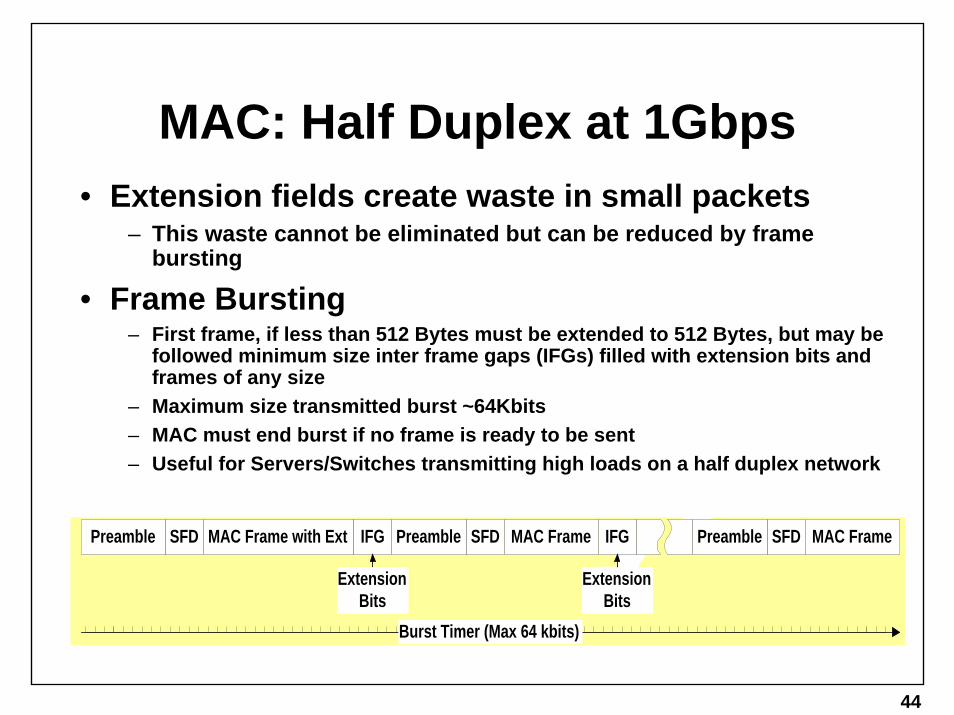
MAC: Half Duplex at 1Gbps• Extension fields create waste in small packets
– This waste cannot be eliminated but can be reduced by frame bursting
• Frame Bursting– First frame, if less than 512 Bytes must be extended to 512 Bytes, but may be
followed minimum size inter frame gaps (IFGs) filled with extension bits and frames of any size
– Maximum size transmitted burst ~64Kbits– MAC must end burst if no frame is ready to be sent– Useful for Servers/Switches transmitting high loads on a half duplex network
MAC Frame with Ext IFG MAC Frame IFG MAC Frame
ExtensionBits
Preamble
ExtensionBits
SFDPreamble SFD Preamble SFD
Burst Timer (Max 64 kbits)

45
Buffered Distributors• Very rare devices - That said, they are far more common than
half-duplex 1 Gbps devices (which are essentially non-existent) Why?
• Where a repeater is a “bus in a box”, a buffered distributor (BD) is “CSMA/CD in a box”.
– Each attached device is connected to an input buffer via a full duplex link. If the input buffer is full, the BD uses PAUSE frames to stop traffic from the attached device. When a frame is removed from the input buffer, it is transmitted out all other ports – hence BDs are sometimes called “Full duplex repeaters”
– Thus the collision domain is the maximum delay within the box, infact, the medium access method used in the box need not be CSMA/CD, so long as it is fair.
• Benefit: Silicon cheaper than a switch (max speed 1Gbps) and less complex than frame extension and bursting
• These are not specified in the standard explicitly, but all the “enabling mechanisms” are - device internals (ie: “bus in a box”) rarely need to be standardized

46
Ethernet JUMBO Frames
• BAD IDEA• Recall that HALF DUPLEX 1 Gig Ethernet
chose to use extension bits to pad a frame out to 512Bytes to enable a larger collision domain
• Why didn’t they just change the frame size? (change the min to 512Bytes, and max to, oh say, 4K or 9K)
• Because such equipment would NOT work with any previously deployed equipment –NOT a smart move for the WORLDS most popular networking technology.
47
Jumbo Frames cont. 1
• The Problem:• “Software”/Users think that this is a simple
problem – simply change the MTU (max transmission unit) to 4K (or more) then let the switches adapt the frame size (fragment and reassemble – this is HARD HARD HARD to do in hardware – read as, costly) -- OR –don’t care about backward compatibility (interesting world you live in then… can I join you?)

48
Jumbo frame cont. 2
• The Reality:• Hardware is built with certain expectations
about frame sizes, interframe-gaps, and transmission rates – simply “changing” the MTU of your system and using hardware not built for Jumbo frames WILL RESULT in frame/data loss (things called “elasticity buffers”, which bridge digital clock domains in systems, must be built with these “certain expectations”) --- not to mention buffer allocation problems, etc…

49
Jumbo frames cont. 3• That said, Jumbo frames _are_ out there but
they are NON-STANDARD• But be careful (SANs like iSCSI intend to
use them, but there are real risks there)• And don’t PLAN on them working beyond
the SINGLE vendor’s equipment that you are using them with (yes, there’s a good chance that multi-vendor jumbo frames would work – but that’s what a standard would protect – and I assure you – IEEE 802.3 will NEVER adopt a larger frame size, as they are COMMITTED to supporting the installed base.

50
This page left intentionally blank.

51
This page left intentionally blank.

52
This page left intentionally blank.

53
Physical Media Overview

54
Media Outline
• Copper and Copper and Copper• Fiber and Fiber

55
Structured Cabling
• Defines a generic telecommunications cabling system for commercial buildings.
• Specifies the performance of the cable and connecting hardware used in the cabling system.
• Why?– The installation of a cabling system is simpler and cheaper during
building construction than after the building is occupied.– Such a cabling system must have the flexibility to allow the
deployment of current and future network technologies.– A structured cabling standard provides a design target for the
developers of new network technologies (like 1000BASE-T).

56
Structured Cabling Standards
• TIA/EIA-568-A, North America• ISO 11801, International• Scope:
– define performance of unshielded twisted pair (UTP), shielded twisted pair (STP), and fiber optic cables and connecting hardware.
– define how these cables will be used in a generic cabling system.
• Both standards define similar distribution systems and performance requirements.
– developers do not have to hit two separate targets
57
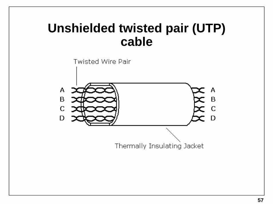
Unshielded twisted pair (UTP) cable

58
The Category System
• TIA/EIA-568-A defines a performance rating system for UTP cable and connecting hardware:
– Category 3 performance is defined up to 16MHz.– Category 4 performance is defined up to 20MHz.– Category 5 performance is defined up to 100MHz.
» Original Cat 5 - Not suitable for 1000Base-T» Category 5n - Suitable for 1000Base-T» Category 5e - Exceeds requirements for 1000Base-T
– Category 6 performance is defined up to 200MHz

59
Performance Parameters for UTP Cable
• DC resistance• characteristic impedance and structural
return loss• attenuation• near-end crosstalk (NEXT) loss• propagation delay

60
Parameters for UTP Connecting Hardware
• DC resistance• attenuation• NEXT loss• return loss

61
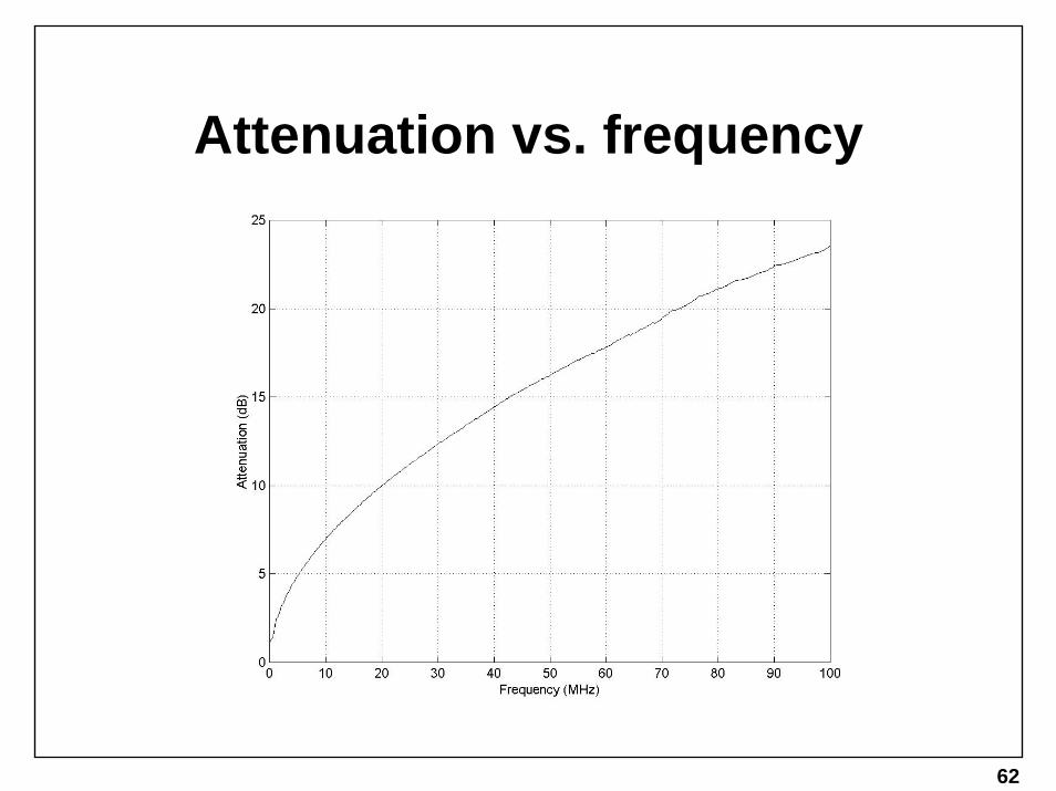
Attenuation
• Electrical signals lose power while traveling along imperfect conductors.
• This loss, or attenuation, is a function of conductor length and frequency.
• The frequency dependence is attributed to the skin effect.
• Skin Effect:– AC currents tends to ride along the skin of a conductor.– This skin becomes thinner with increasing frequency.– A thinner skin results in a higher loss.
• Attenuation increases up to 0.4% per degree Celsius above room temperature (20oC).
62
Attenuation vs. frequency

63
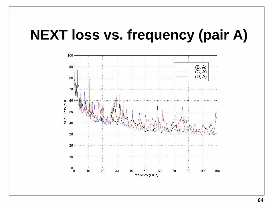
Near-end crosstalk (NEXT) loss
• Crosstalk:– Time-varying currents in one wire tend to induce time-
varying currents in nearby wires.• When the coupling is between a local transmitter and
a local receiver, it is referred to as NEXT.• NEXT increases the additive noise at the receiver and
degrades the signal-to-noise ratio (SNR).
64
NEXT loss vs. frequency (pair A)

65
Return loss
• The reflection coefficient is the ratio of the reflected voltage to the incident voltage.
• The return loss is the magnitude of the reflection coefficient expressed in decibels.

66
Structured cabling overview I
• Work area– for example, an office
• Telecommunications closet– focal point of horizontal cabling– access to backbone cabling and network equipment
• Equipment Room– can perform any of the functions of a telecommunications closet– generally understood to contain network resources (for
example, a file server)
• Entrance Facility– the point at which the network enters the building, usually
in the basement

67
Structured cabling overview II• Horizontal Cabling
– from the work area to the telecommunications closet.– up to 90m of 4-pair unshielded twisted pair (UTP) cable.
• Backbone Cabling– between telecommunications closets, equipment rooms, and
entrance facilities.– up to 90m of 4- or 25-pair UTP cable.
• Flexible Patch Cords– cables use solid conductors making them inflexible and difficult to
work with– cords use stranded conductors for greater flexibility at the
expense of up to 20% more loss than the same length of cable.– cords are used at points where the network configuration will
change frequently

68
Structured cabling overview III
• Transition point – connects standard horizontal cable to special flat cable designed to run
under carpets.
• Cross-connect– a patch between two interconnects– horizontal and backbone cabling runs end at interconnects– network equipment may use an interconnect
• For UTP cabling systems, horizontal and backbone runs are always terminated in the telecommunications closet and equipment room
– for example, you cannot cross-connect a horizontal run to a backbone run.

69
Structured cabling system example

70
TIA/EIA-568-A channel definition
• 90m of horizontal cable• 10m of flexible cords• 4 connectors• ISO 11801 channel definition does not include a
transition point (3 connectors).• The channel definition is the developer’s design
target.

71
UTP Copper Info
• Two types of UTP – Solid Core (for Horizontal runs) and Stranded Core (for patching)
• RJ-45 connectors – when making cable:– solid: use 8-pin modular (RJ-45) plug with three prongs
on the metal contacts– stranded: two prongs on metal contacts
• Wiremap – there are four pairs in a normal UTP cable: orange, green, blue, and brown. In each pair there is a white wire with a colored stripe and a colored wire with a white stripe. By convention, the white wire carries the signal and the colored wire carries the inverted signal.

72
More UTP Copper Info• looking down at the top of the RJ-45 (locking tab facing down )
• A good UTP cable will have:– All 8 wires visible at the very end of the RJ45 cable– The Jacket of the cable fully inserted into the RJ45 (so when you
pull on the cable, you pull the jacket and the RJ45, and not thewires and contacts)
SolidWhite,OrangeStripe
SolidOrange,WhiteStripe
SolidWhite,GreenStripe
SolidBlue,WhiteStripe
SolidWhite,BlueStripe
SolidGreen,WhiteStripe
SolidWhite,BrownStripe
SolidBrown,WhiteStripe
1 2 3 4 5 6 7 8
73
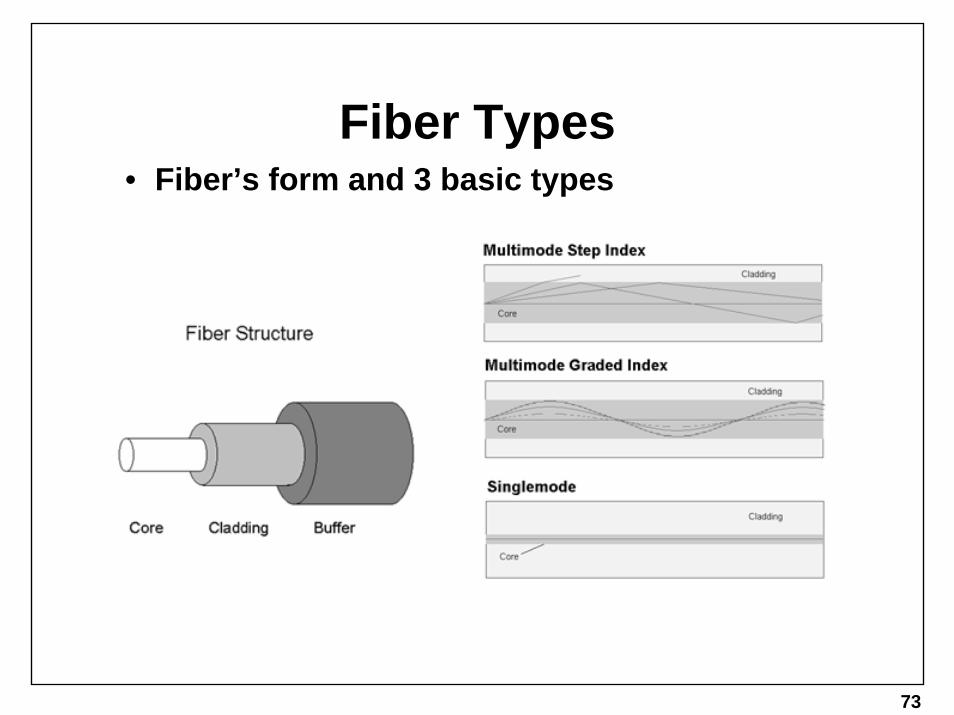
Fiber Types• Fiber’s form and 3 basic types

74
Fiber Core Sizes
• Multimode: Two most common are 62.5 and 50 micron
• Singlemode – To be singlemode, diameter must be no more than ~6 times the wavelength, thus for 1330 – 1510 nm light, the diameter must be 7 to 9 micron
• Mismatching core sizes can be done, but in general is bad!

75
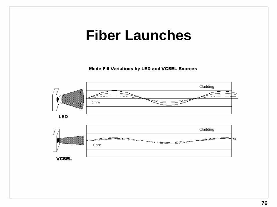
Modal Dispersion
• A flashy name to describe how in a multi-mode fiber, the multiple paths arrive at the end of the fiber at different times.
• This multi-path delay causes a “small” input pulse to smear into a “wide” output pulse, degrading the rate at which those data pulses can be sent down the fiber (degrading the bandwidth)
• Note that a multimode step index fiber has high modal dispersion, as a result, such fiber is not typically used today.
• Graded index fiber varies the refraction index of the fiber material from the center of the fiber out to its edge. The result is that the modes traveling the longer sinusoidal paths actually propagate faster than the modes traveling the shorter, straighter paths –thus, in a perfect graded index fiber, all modes would arrive at the same time at the output of the fiber, and no smearing would occur. (of course perfection is impossible to achieve)
76
Fiber Launches

77
Recent Modal Dispersion Issues
• As a side-note: During the development of Gigabit Ethernet, it was discovered that a sizeable percentage of installed (old) multimode graded index fiber had a deviation in the center of the core, as depicted at left. This was determined to cause increased modal dispersion (DMD, differential modal delay as the gig folk called it)
• The result of this discovery of a flaw in the installed media was the subsequent reduction in supported link lengths for GbEon installed multimode fiber.
• Which leads to the following new term…

78
Launch Conditioning• Many options exist to minimize the DMD effect, one of which
is to use a single-mode “pig-tail” to condition/reduce the modes launched into the multi-mode segment, by launching them off-center (and thus avoiding the index “notch” in the center of the installed fibers)

79
Chromatic Dispersion
• Effects all fiber types, but is one of the primary limiting factors of long-haul single-mode connections.
• As mentioned earlier, EM waves propagate at different speeds in different media. Well, simply put, EM waves at different frequencies propagate at different speeds, even in the same media! In general, this is referred to as group delay, but in Fiber Optics, its more commonly called chromatic dispersion.
• This spreading of different colors smears the transmitted pulses just as with modal dispersion

80
Bad Fiber Connections
• Always keep your Fiber CLEAN! And Capped when not in use (both patch and ports)

81
Some Types of Connectors
LC
Especially note SC, ST, LC, and MTRJ
MTRJ

82
Most Common Connectors
• ST
• SC
• MTRJ and LC to SC
83
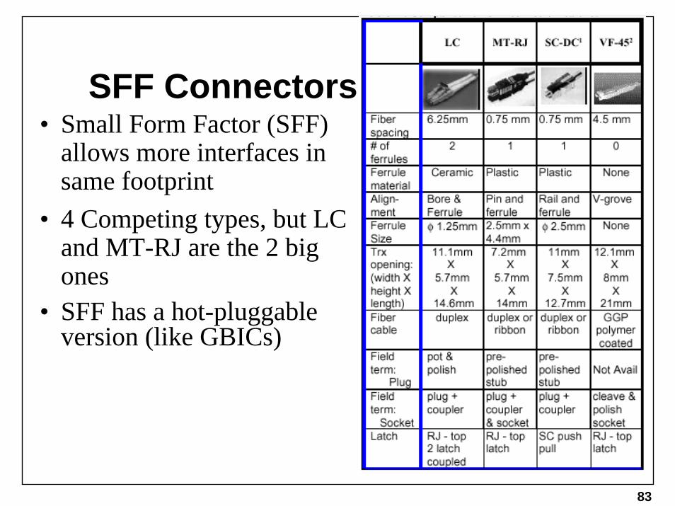
SFF Connectors• Small Form Factor (SFF)
allows more interfaces in same footprint
• 4 Competing types, but LC and MT-RJ are the 2 big ones
• SFF has a hot-pluggable version (like GBICs)

84
Fiber Info• Not only must the fiber be kept clean, but its end
should be polished (to eliminate scratches) and rounded.
• The rounding of the ends allows the two fiber ends to touch without an airgap forming between them.
• DO Keep your fiber clean. If in doubt, use anairgun or alcohol swab to clean the ends.
• DO Keep your fiber capped when not in use (to prevent dust and scratches)
• DO Keep fiber ports on devices capped when not in use – dust collected on a transmitter or receiver can only – at best, be blown at with an airgun.

85
More Fiber Info
• DON’T EVER allow the fiber to bend more than the diameter of your closed fist. Fiber is glass, bent glass breaks and/or creates microfractures.
• DON’T touch the tip of the fiber with your finger/body – The core may be protruding and slice you open (it is glass!)
• DON’T look down a fiber! Its YOUR EYESIGHT at stake!! Use a power meter to check your cable!
• Quick way to test fiber / find the right fiber –Hold one fiber at the far end up to a light, look in the other end to find the white dot! – If you don’t see it, it’s the wrong fiber, or its EXTREMELY broken.

86
This page left intentionally blank.

87
This page left intentionally blank.

88
This page left intentionally blank.

89
Core PHYs

90
Core PHYs Outline
• Review of the Physical layers role• UTP Copper Phys• Fiber Phys
• Primary focus on 10Base-T, 100Base-TX, and 1000Base-T

91
Review• MAC
– Sends/Receives data to/from higher layer client– Handles addressing of data frames for the LAN– Appends a checksum to ensure frame validity on reception
• Medium– Available channel in infrastructure for data transmission– May be copper or fiber– Medium selected is typically a matter of cost and installed base
• PHY – Physical Layer– Prepares MAC frame for Medium– Drive signal across Medium (Tx to Rx)
92
PHY Objectives
• Balance of the following desirables:– Low Cost– Long Distance– High Data Rate capability– Low Bit Error Rate – Support the current installed media when possible

93
PHY Stack Model - Slide 1
• Notice the PHY connects the SAME MAC layer to different types of Media, the four most common are shown:

94
PHY Stack Model – Slide 2• To support different media, different PHYs are
required.• Each PHY balances the objectives (cost, speed,
etc) differently

95
PHY Evolution• 1985 – IEEE 802.3 – 10Base-5 & 10Base-2• 1987 – IEEE 802.3d – FOIRL • 1990 – IEEE 802.3i – 10Base-T • 1993 – IEEE 802.3j – 10Base-F• 1995 – IEEE 802.3u – 100Base-T4 / TX / FX• 1997 – IEEE 802.3y – 100Base-T2• 1998 – IEEE 802.3z – 1000Base-SX / LX /
CX• 1999 – IEEE 802.3ab – 1000Base-T
96
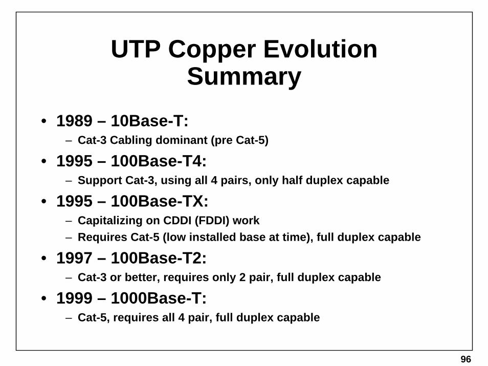
UTP Copper Evolution Summary
• 1989 – 10Base-T: – Cat-3 Cabling dominant (pre Cat-5)
• 1995 – 100Base-T4:– Support Cat-3, using all 4 pairs, only half duplex capable
• 1995 – 100Base-TX: – Capitalizing on CDDI (FDDI) work – Requires Cat-5 (low installed base at time), full duplex capable
• 1997 – 100Base-T2:– Cat-3 or better, requires only 2 pair, full duplex capable
• 1999 – 1000Base-T:– Cat-5, requires all 4 pair, full duplex capable

97
10BASE-T Overview
• 10 Mbps (Million Bits per second)• Category 3 cable (voice-grade) or better• 2 pairs DATA (1,2 & 3,6) leaves center pair
(4,5) for PHONE • 100 meter runs (limited by cable
attenuation) – All that’s necessary to support building structured cabling
• Star/Hub Topology• Inherently Full Duplex (Upper layer
MAC/Repeater may be half duplex though)

98
10BASE-T: Data Encoding• 10base-T uses Manchester Encoding• + to - transition = “0” - to + = “1”• Always DC balanced & Always has a transition
each bit-time for clock recovery.

99
10BASE-T: Between the frames
• Idle between frames is filled with Link Test Pulses (LTPs)
• Periodically signal presence of link partner

100
10BASE-T: Preamble and SFD• Preamble allows device to recover clock of link
partner• Since “x” bits will be lost until clock is recovered,
start frame delimiter (SFD) marks byte boundary• Recall: Preamble: 7bytes 10101010 SFD=
10101011

101
10BASE-T: AUI• Model at right for all
10Mbps Ethernet PHYs including:
– 10BASE-2, 10BASE-5, 10BASE-T, 10BASE-FP / -FB / -FL
• Attachment Unit Interface (AUI) allows different PHYs to be attached to the MAC. Also used in repeaters.
• Medium Attachment Unit (MAU) = PHY

102
100BASE-T4 Overview• 100Mbs• Cat-3 or Better, 100 meter max• Uses all 4 pair
– Transmits on 3 pair, listens for collision on 4th. – Creates half-duplex only limitation in PHY
• Extinct – Why?– Introduced at same time as 100Base-TX(Cat-5 or better) when
10Base-T(Cat-3 or better) was prevalent. – 100Base-TX based on pre-existing CDDI, thus low cost TX chips
emerged rapidly– Provided customers with option –
» Buy T4 equipment supporting installed base of Cat-3 » OR… Install new Cat-5 cable and buy TX equipment » Most choose to install new cable to “future proof” network

103
100BASE-TX Overview
• The critter commonly called Fast Ethernet• 100 Mbps• Category 5 cable (data-grade) or better• Same 2 pairs for DATA as 10BASE-T (1,2 &
3,6)• 100 meter runs (limited by cable
attenuation)– All that’s necessary to support building structured cabling
• Inherently Full Duplex (Upper layer MAC/Repeater may be half duplex though)

104
100BASE-TX: Data Encoding• 4B/5B Block Code• 4B/5B means 100Mbps data requires 125Mbps on
the media (a 25% speedup – resulting in 20% overhead(non-databits transmitted)
• Why is this useful? Creates control codes.• “I” (Idle) = 11111 Which is sent continuously to
provide a good clock to the link partner’s receiver• “J” and “K” = 11000 & 10001 – Start of Frame,
unique bit pattern, cannot be made from any combination of other VALID symbols
• 2^5=32 symbols, only need 16 (2^4) symbols for data, 1 for idle, 2 for start of frame, 2 for end of frame, rest are invalid

105
100Base-TX: 4B/5B Tables

106
100BASE-TX: MLT-3 Coding• 5B Idle code is 11111, at 125Mbs (NRZI) that’s a
125MHz tone, recall cat-5 performance specification ends at 100MHz!
• Multi-Level Transition with 3 levels a.k.a. MLT-3 Reduces frequency of 5B encoded data.
• If data is “1”, then transition from current level to next level. ie 1111=+1,0,-1,0 reducing freq by 1/4
• If bit data is “0”, then don’t transition
MLT-3
0 1 1 10 0 0 1 1 1 0 0bit

107
100Base-TX: MLT-3 Eye Diagram
• 1-Bit Time shown, with all possible transitions

108
100BASE-TX: Scrambling• MLT-3 successfully reduces frequency of 5B
encoded data, but recall the 5B idle stream is sent continuously between frames.
• After MLT-3 encoding, Idle went from a 125MHz tone to a 31.25MHz tone (125/4). Since most of the transmitted energy is at this frequency, it radiates strongly, which the FCC does not like, hence…
• Scrambling of the 5B encoded stream is required. • Prior to MLT-3 encoding, the 5B stream is pseudo-
randomly scrambled, this breaks up the repeating 1s and spreads the transmitted energy across many frequencies, thus no single frequency has much energy.

109
100BASE-TX: Media Independent Interface

110
100BASE-T2
• 100Mbs• Cat-3 or Better• Uses only 2 pair
– Uses 5 level signaling– Transmits and receives on both pairs simultaneously– Allows use of other pairs. – Full-duplex capable
• Extinct – Why?– Limited market potential due to 100Base-TX

111
1000BASE-T Overview
• 1000Mbs• Cat-5 or Better• Uses all 4 pair
– Uses 5 level signaling– Transmits and receives on both pairs simultaneously – Full-duplex capable
• Emerging –– Growing number of PHY chip vendors– 10/100/1000 single chip solutions and multiport chips
112
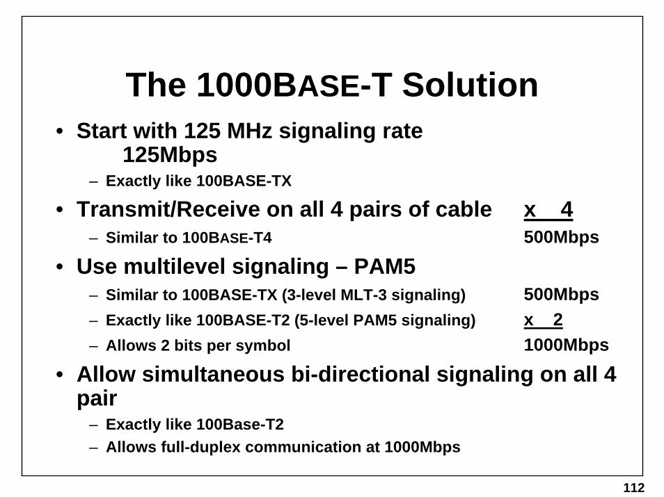
The 1000BASE-T Solution• Start with 125 MHz signaling rate
125Mbps– Exactly like 100BASE-TX
• Transmit/Receive on all 4 pairs of cable x 4 – Similar to 100BASE-T4 500Mbps
• Use multilevel signaling – PAM5– Similar to 100BASE-TX (3-level MLT-3 signaling) 500Mbps– Exactly like 100BASE-T2 (5-level PAM5 signaling) x 2– Allows 2 bits per symbol 1000Mbps
• Allow simultaneous bi-directional signaling on all 4 pair
– Exactly like 100Base-T2– Allows full-duplex communication at 1000Mbps

113
1000Base-T: 4D-PAM5
• 4 Dimensional Pulse Amplitude Modulation with 5 levels
• 5 levels on 4 pairs yields 625 possible symbols (5^4)• To encode 8bits every 8ns (125MHz), only 256
symbols are needed (2^8). • Remaining symbols can be used for control
characters (idle, start of packet, end of packet, etc).• Data frames are transmitted using a convolutional
(Trellis) code– Adds structure to the transmitted symbols needed for Viterbi
Decoding
114
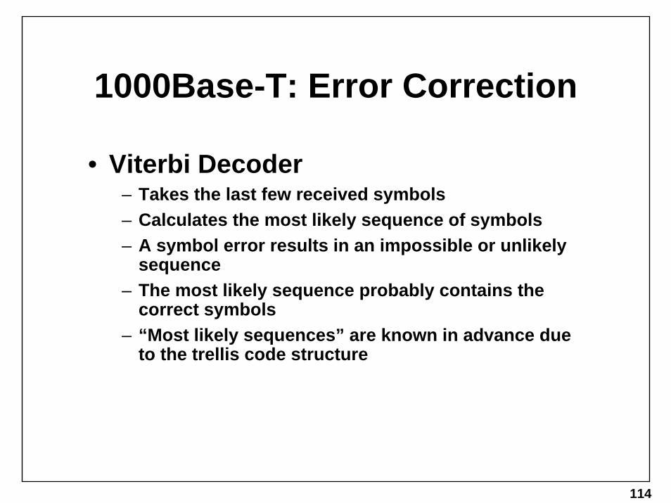
1000Base-T: Error Correction
• Viterbi Decoder– Takes the last few received symbols– Calculates the most likely sequence of symbols– A symbol error results in an impossible or unlikely
sequence– The most likely sequence probably contains the
correct symbols– “Most likely sequences” are known in advance due
to the trellis code structure

115
1000Base-T: Noise Environment

116
1000Base-T: DSP• Digital signal processing (DSP) techniques can
reduce effects of echo and NEXT– These are caused by local transmissions– Tap the signal on all 4 transmitters– Cancel out these signals from the received waveform
• ELFEXT is not easily cancelled with DSP– Originates from remote transmitters– Relies on cable and connectors to meet new Cat5 specification, so
that ELFEXT is minimal
• Alien Crosstalk also unpredictable– Unknown source– Thus, cannot be cancelled
• 25-pair bundles not allowed!– Crosstalk between bundled pairs too high
117
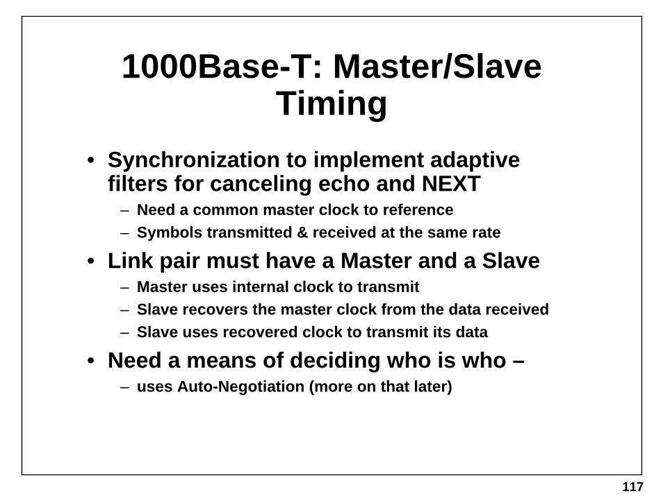
1000Base-T: Master/Slave Timing
• Synchronization to implement adaptive filters for canceling echo and NEXT
– Need a common master clock to reference– Symbols transmitted & received at the same rate
• Link pair must have a Master and a Slave– Master uses internal clock to transmit– Slave recovers the master clock from the data received– Slave uses recovered clock to transmit its data
• Need a means of deciding who is who –– uses Auto-Negotiation (more on that later)

118
10, 100, 1000 Signal Comparison

119
UTP Copper Phys Wrap-up
• Combo PHYs– 10/100 PHYs – 10Base-T & 100Base-TX– 100/1000 PHYs – 100Base-TX & 1000Base-T– 10/100/1000 PHYs – emerging
• Quad / Hex / Octal PHYs– Reduces chip and other component count required to
manufacture multiport devices, thus lower cost.– Most multi-phy devices are also Combo PHYs

120
Fiber Evolution Summary• 1987 – Fiber Optic Inter-Repeater Link (FOIRL):
– Link 10Mbps repeaters via multimode fiber (2km max)
• 1993 – 10Base-F:– 10Mbps to end stations via multimode fiber (2km max)
• 1995 – 100Base-FX: – Capitalizing on FDDI work – 100Mbps via multimode fiber (2km max) to repeaters or end
stations
• 1998 – 1000Base-SX / LX:– Capitalizing on FibreChannel work, but spedup– 1000Mbps

121
10Mbps Fiber Overview• All use multimode fiber, driven by LEDs• FOIRL: Fairly common
– FOIRL = Fiber Optic Inter-Repeater Link– Typical use: FOIRL Medium Attachment Unit (MAU) attached to
Attachment Unit Interface (AUI) of repeaters w/o built in fiber support
• 10BASE-F– Catch all for 10Base-FP, 10Base-FB, 10Base-FL
• Distances:– 10Base-FP: 500m max– All others: 2000m max – limited by cable attenuation
• Same speed, but different techniques – identical type of MAU required on both sides of fiber

122
100BASE-FX Overview
• 100 Mbps• Multimode Fiber• Inherently Full Duplex (Upper layer
MAC/Repeater may be half duplex though)• Full Duplex Distance: 2000 meter runs
– Limited by cable attenuation
• Half Duplex Distance: 412 meters – Point-to-point link, no repeaters– Limited by collision domain

123
100BASE-FX: Similar to -TX
• Like all 100Mbps Fast Ethernet, supports Media Independent Interface (MII)
• Like 100BASE-TX, uses 4B/5B Coding to encode data and idle
• Similarity ends here though – No need for:– Scrambling– MLT3 Encoding
• Why? – MLT3 is unnecessary due to high bandwidth of fiber– Scrambling is unnecessary as fiber does not radiate, thus
no possibility of interference.

124
1000BASE-SX/LX Overview
• 1000 Mbps• Multimode Fiber for SX or LX• Singlemode Fiber for LX only• Inherently Full Duplex (One fiber for Tx, one
for Rx)– Upper layer MAC may be half duplex, but this is highly
unlikely
• Distance:– Tricky issue

125
1000Base-SX/LX: Distance and Launch Cable
• Remember from the physical media section the following two slides…

126
Recent Modal Dispersion Issues
• As a side-note: During the development of Gigabit Ethernet, it was discovered that a sizeable percentage of installed (old) multimode graded index fiber had a deviation in the center of the core, as depicted at left. This was determined to cause increased modal dispersion (DMD, differential modal delay as the gig folk called it)
• The result of this discovery of a flaw in the installed media was the subsequent reduction in supported link lengths for GbE on installed multimode fiber.
• Which leads to the following new term…

127
Launch Conditioning• Many options exist to minimize the DMD effect, one of which
is to use a single-mode “pig-tail” to condition/reduce the modes launched into the multi-mode segment, by launching them off-center (and thus avoiding the index “notch” in the center of the installed fibers)

128
Wavelength vs. Attenuation

129
1000Base-SX Distances
• Modal Bandwidth refers to the quality of your installed MM fiber.
• Recall, SingleMode Fiber (SMF) is not supported for SX• Greater distances are likely, but not recommended by the
standard
130
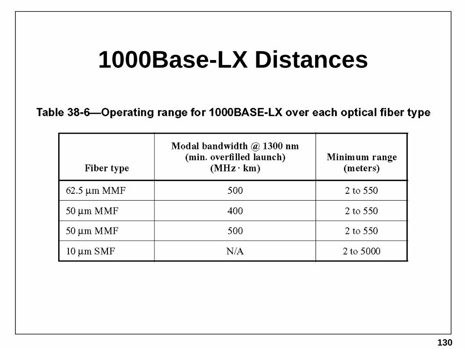
1000Base-LX Distances

131
1000Base-SX/LX: Data Encoding
• 8B/10B Block Code• Code developed by IBM in the 80s, used by
FibreChannel.• Like 4B/5B, has 20% overhead, used not only for
control characters (idle, start of packet, end of packet) but also for data code redundancy.
• Running Disparity: – Every data code has a + and a – running disparity version– The form of each data code determines whether the NEXT data
code should be + or –– If data is received that does not follow the running disparity rules,
then an error has occurred.

132
Non-Standard Interfaces
• 1000Base-LH– Provides up to 10km distances over single mode– Interoperates with LX for 5km (same wavelength, just
higher transmit power and lower receive sensitivity)
• 1000base-XD– Provides up to 50km distances over single mode– Does not interoperate with any other interface type
• 1000Base-ZX– Provides up to 70km distances over single mode (100km
on dispersion shifted fiber)– Does not interoperate with any other interface type

133
GBIC• GigaBit Interface Converter –
industry agreement (SFF Committee)
• Allows for hot-pluggable transceiver
• Support both 1000Base-SX and LX, so user can choose after purchasing the box

134
This page left intentionally blank.

135
This page left intentionally blank.

136
This page left intentionally blank.

137
Autonegotiation
Clauses 28 and 37 of 802.3

138
Autonegotiation vs. Autosensing
• Autonegotiation– standardized speed handshake– auto-configures to best possible link
(e.g., 100 full duplex)– still links with older or non-autoneg
devices– sometimes causes autosensing
(NOT autonegotiating) devices to link at 10 and not 100
– user error/misunderstanding cause problems
• Autosensing/Speed Detection
– several different proprietary methods
– only auto-configures to 10 or 100, not duplex settings
– creates many interoperability headaches

139
ISO-OSI model
Application
Session
Transport
Network
Data Link
Presentation
Physical
LLC - Logical Link Control
MAC - Media Access ControlReconciliation
AUTONEG
MII
MDImedium
PCSPMAPMD

140
Autonegotiation - How?• Constantly sends out 10base-T Link Test Pulses before linking• The pulses are grouped together in defined “words” that convey
meanings, such as “I can do 100 half and full duplex”• Older 10base-T devices just think they’re LTPs• Autoneg devices understand them as words and exchange
handshake info to link at best possible link• If the autoneg device sees regular LTPs coming in (not autoneg
words), it just links at 10 half duplex• If the autoneg device sees Fast Ethernet IDLE stream coming in, it
just links at 100 half duplex.• Unfortunately, this only works on copper for 10/100 - it’s supported
on fiber and copper for gig (i.e., there is no autonegotiation for 100base-FX)

141
NLP (Normal Link Pulse)
this is typically 100 ns in width
•Looks just like a 10base-T Link Test Pulse (LTP)

142
When do we care aboutNLPs?
•When the NLPs are spaced apart they look just like normal 10base-T Link Test Pulses (LTPs)
•So an old 10base-T legacy device will see them as normal link
•But a legacy device won’t care if we send the NLPs more often than normal, so...
16 +/- 8 ms

143
When they are FLP Bursts!•Stick a bunch of NLPs together and use it to signal info (like Morse code)
Burst width = 2 ms
beginning of next FLP
FLP Burst (17 NLP “clock pulses”)
16 +/- 8 ms
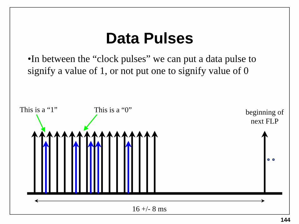
144
Data Pulses•In between the “clock pulses” we can put a data pulse to signify a value of 1, or not put one to signify value of 0
beginning of next FLP
This is a “1” This is a “0”
16 +/- 8 ms

145
right….What’s an FLP for again?
Selector Field
The data fields are pre-defined for specific meanings
The selector field is used for version info, such as “802.3 version 1 The NLPs used are all the same
voltage level (height), I just draw the data ones shorter to distinguish
them from the clock ones.

146
right….What’s an FLP for?The Technology Ability Field is used to signal which modes the device can handle, for example 100base-T Full Duplex
Technology Ability Field10BTHDX
10BTFDX
100BTHDX
100BTFDX
100T4
reserved for the FUTURE
Selector Field
PauseAsym.Pause

147
right….What’s an FLP for again?
The last fields are used to tell the link partner of a remote fault, acknowledge the receipt of its partner’s FLPs, or that there are more “pages” of FLP fields to send
10BTHDX
10BTFDX
100BTHDX
100BTFDX
100T4
RemoteFault ACK NP
Selector Field Technology Ability Field
PauseAsym.Pause

148
A Sample FLP
Selector Field Technology Ability Field
10BTHDX
10BTFDX
100BTHDX
100BTFDX
100T4
RemoteFault ACK NPPause
Asym.Pause

149
How It Works: 2 Aneg Devices
• Device A sends FLPs out, while Device B does the same
• Each device receives the other’s FLPs and sets their ACK bit to true (a value of “1”)
• They then choose the best possible mode that both support and start transmitting IDLE, and it’s linked!
Device ATX
RX
Device BRX
TX
Aneg10/100HD/FD
Aneg10/100HD/FD
100MbpsFull Duplex
100MbpsFull Duplex

150
How It Works: an Aneg Device with a
10Mbps Legacy Device• Device A sends FLPs out, while Device B sends out
LTPs• Device A “parallel detects” the LTPs and links with
Device B in 10mbps half-duplex mode
Device ATX
RX
Device BRX
TX
Aneg10/100HD/FD
10Mbps Half or Full
Duplex
10MbpsHalf
Duplex
Warning!

151
How It Works: an Aneg Device with a
100Mbps Legacy Device• Device A sends FLPs out, while Device B sends out
Fast Ethernet IDLE• Device A “parallel detects” the IDLE and links with
Device B in 100mbps half-duplex mode
Device ATX
RX
Device BRX
TX
Aneg10/100HD/FD
100MbpsHalf
Duplex
100Mbps Half or Full
Duplex
Warning!

152
Autoneg Problems
• Three types of problems are sometimes encountered:
1) A Duplex mismatch occurs whereby one side is Half-Duplex, one side is Full-Duplex
2) The wrong speed link is used (10 instead of 100)3) The devices never link
• Let’s look at how these happen...

153
Aneg Error #1: User Misconfiguration
User configures Device B to be 100Mbps Full Duplex, not knowing this disables Autoneg (sending FLPs)Device A sends FLPs out, while Device B sends out IDLEDevice A sees IDLE and assumes Device B is 100Mbps Half-Duplex, thus it links in Half-Duplex mode
Device ATX
RX
Device BRX
TX
Aneg10/100HD/FD
100MbpsHalf
Duplex
100Mbps Full
Duplex
Mismatch

154
Duplex Mismatch ProblemIf Device A and B send out a frame at the same time, then:
1) Device A will believe a collision occurred and corrupt its outgoing frame while discarding Device B’s frame, and then attempt to resend its own frame2) Device B will not resend its frame, and see Device A’s frame as corrupted
Device ATX
RX
Device BRX
TX
Aneg10/100HD/FD
100MbpsHalf
Duplex
100Mbps Full
Duplex

155
Duplex Mismatch SymptomsDevice A will record many “Late Collisions” in its countersDevice B will record many “CRC Errors” in its countersThe connection will appear slow, as the dropped frames aren’t resent until a higher layer times out (usually 1 second later)
Device ATX
RX
Device BRX
TX
Aneg10/100HD/FD
100MbpsHalf
Duplex
100Mbps Full
Duplex

156
Aneg Error #2: User Misconfiguration
• User configures Device A for 100Mbps Full-Duplex and Device B for Half-Duplex (or Device B is only Half-Duplex) while leaving Aneg (sending FLPs) turned on for both
• Each device receives the other’s FLPs, but the mismatch never resolves to a link because there is no common option
Device ATX
RX
Device BRX
TX
Aneg100Mbps
Full Duplex
Aneg100Mbps
Half Duplex

157
Aneg Error #3: Autosensing Devices
Autosensing devices do not use FLPsInstead, they send IDLE while watching the RX line for LTPs or IDLE and decide based on thatSo Device A will send FLPs, which Device B will interpret as LTPs and switch to transmitting LTPs itselfMeanwhile, Device A may have seen the IDLE from B and “parallel detected” over to sending 100Mbps IDLE, which Device B will now see as 10Mbps junk data (yes, this is legal) - this should fix itself in a few seconds, or never
Device ATX
RX
Device BRX
TX
Aneg10/100HD/FD
100MbpsHalf
Duplex
Autosensing
10/100 HD
10MbpsHalf
Duplex

158
Aneg Error #3: Autosensing Devices
OR, Device A will see the LTPs from Device B and parallel detect to 10mbps, thereby successfully forming a 10mbps link, which is notoptimal
Device ATX
RX
Device BRX
TX
Aneg10/100HD/FD
10MbpsHalf
Duplex
Autosensing
10/100 HD
10MbpsHalf
Duplex

159
Gigabit Ethernet Autonegotiation
• Gigabit Ethernet uses the same Aneg mechanism as 10/100 copper Ethernet (remember there is no Aneg for 10 or 100 fiber)
• For 1000base-SX and 1000base-LX, it’s used to determine duplex and flow-control parameters using the pre-defined fields shown below
• For 1000base-T, the Next Page field is used to indicate there is additional info that must be exchanged using more “pages”
FDX HDX Pause Asym.Pause
RemoteFault 2ACK NPReserved Remote
Fault 1Reserved
Base Page for Gig fiber technologies

160
Gig Aneg Error #1: User Misconfiguration
• There are almost no Half-Duplex Gig devices, so we never have the mismatch problem of 10/100 Aneg
• The biggest problem is when users configure one device to “Autoneg Enabled” and the other device to “Autoneg Disabled”
• Such misconfigured devices will not link, or only one side will think it’s linked
Device ATX
RX
Device BRX
TXAneg
1000base-SX or LX
Not Aneg1000base-SX or LX

161
Gigabit Copper Autonegotiation
• For 1000base-T, the Next Page field is used to indicate there is additional info that must be exchanged using more “pages”
• These pages contain the same type of info regarding duplex and speeds, but they also contain a couple new things:
– a field to indicate whether the device is a single-port or multi-port device– a field for whether the master/slave determination is manually configured– a field for whether this device is the master or slave– a seed value
10BTHDX
10BTFDX
100BTHDX
100BTFDX
100T4
RemoteFault ACK NPPause
Asym.Pause
Selector Field Technology Ability Field
Base Page for Gig copper technologies

162
Gigabit Copper Autoneg (cont.)
• The purpose for the new fields is to resolve which side is the master and which the slave for a training sequence to adjust to the cable characteristics (like a DSL modem does)
• If the user does nothing, then it will automatically select a master based on:
– if one side is multi-port, it is the master– if both sides are or both sides are not multi-port, then the
seed is used to randomly choose
• Or the user can manually configure one to be the master and the other a slave

163
Gig Copper Aneg Error #1: User Misconfiguration
• There are almost no Half-Duplex Gig devices, so we never have the mismatch problem of 10/100 Aneg
• The biggest problem is when users configure one device to “Autoneg Enabled” and the other device to “Autoneg Disabled”
• Such misconfigured devices will not link, or only one side will think it’s linked
Device ATX
RX
Device BRX
TXAneg
1000base-T Master
Not Aneg1000base-T
Slave

164
Gig Copper Aneg Error #2: User Misconfiguration
• A user configures both devices to be master or both to be slave
• Such misconfigured devices will never link - even if they’re also both autonegotiating, or both manual
• The problem is manually configuring master/slave overrides automatically selecting which side is which
Device ATX
RX
Device BRX
TX
1000MbpsManualMaster
1000MbpsManualMaster
165
Power over Ethernet - 802.3af
166
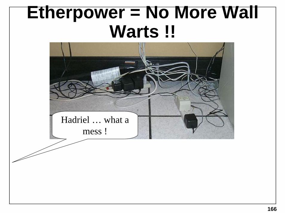
Etherpower = No More Wall Warts !!
Hadriel … what a mess !

167
Data Appliances
48VDC ModularRectifier and Battery Tray
Ethernet Switchesor
‘mid-span insertion’
Power over Ethernet: the concept

168
Power over Ethernet: the details
Mid-span Power Patch Panel
Dongle

169
UTP Copper• looking down at the top of the RJ-45 (locking tab facing down )
• 10base-T and 100base-TX/T2 only use wires 1, 2, 3, and 6 - wires 4, 5, 7, and 8 are unused
• 100base-T4, and 1000base-T use all 8 wires
SolidWhite,OrangeStripe
SolidOrange,WhiteStripe
SolidWhite,GreenStripe
SolidBlue,WhiteStripe
SolidWhite,BlueStripe
SolidGreen,WhiteStripe
SolidWhite,BrownStripe
SolidBrown,WhiteStripe
1 2 3 4 5 6 7 8
170
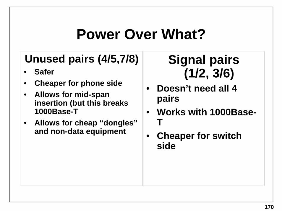
Power Over What?Unused pairs (4/5,7/8)• Safer• Cheaper for phone side• Allows for mid-span
insertion (but this breaks 1000Base-T
• Allows for cheap “dongles” and non-data equipment
Signal pairs (1/2, 3/6)
• Doesn’t need all 4 pairs
• Works with 1000Base-T
• Cheaper for switch side

171
Power Method Options
• Voltage: 44-57v nominal DC• Amperage: 350mA Max • Power: 12.95 Watts max during use• Use either pair sets: the source can feed
power on one or the other, but the sink (device to be powered) will draw it from either
– this makes the receiver (the phone side) more expensive– this allows for both a cheap powered patch panel and
cheap powered switch method– this does not allow both data and unused pairs to send
power simultaneously (not safe)

172
Power Discovery
• Method for power source to determine if connected device needs power
• Needs to be fool-proof (doesn’t fry old stuff)• Needs to be cheap• Needs to work before the other side is
powered up (obviously)• Needs to be safe regardless of cable-type
connected: could be regular, crossover, flipped, wrong, broken
• Uses 19k-26.5kOhm Resistor

173
Houston, we have a problem…
• One company has filed a suit against another for patent infringement
• Their patent covers a security method whereby they monitor a small current (<1ma). If the current drops off then they produce an alarm.
• Power over Ethernet's minimum current is 10ma and if the PD's current draw falls below 10ma then the PSE removes power.
• By sending current over active Ethernet links, their patent may cover power over Ethernet
• If they don’t sign a Fair Use Agreement, the standard will be stopped/blocked

174
…and hopefully a solution
• Power/current detection has been used in this manner “for all time”, including for Token Ring (phantom signaling)
• IEEE will likely persevere, or find a way around this legal snafu
• To continue towards this solution, IEEE P802.3af DTE Power via MDI Interim Meeting will be held Sept 24-26 in Portsmouth, NH, hosted by UNH IOL http://grouper.ieee.org/groups/802/3/interims/portsmouth.html

175
This page left intentionally blank.

176
This page left intentionally blank.

177
10 Gigabit Ethernet - 802.3ae

178
IEEE 802.3ae Objectives• Support full-duplex operation only.• Provide Physical Layer specifications which support link
distances of:– At least 300 m over installed MMF– At least 65 m over MMF– At least 2 km over SMF– At least 10 km over SMF– At least 40 km over SMF
• Define two families of PHYs– A LAN PHY, operating at a data rate of 10.000 Gb/s– A WAN PHY, operating at a data rate compatible with the payload rate
of OC-192c/SDH VC-4-64c

179
Where does 10GE fit ?Data Center
Access
Edge Routers Core Router
Carrier Core DWDM Optical Network (WAN)POP
Extension
Server Farm & Data Center ConnectivityIntra-POP ConnectivityGeographic POP ExtensionInter-POP Connectivity
Switch
Metro
Transport
T1
1
2
4Access
Access
Access
T1
10 GE
Lege
nd
1 GE
DataCenter 1
1234
Key Applications
Server Farm
Optical Network
3
1

TimelineWe Are Here

181

182
The PMDs
• Set of 4 PMDs (Physical Media Dependent) to optimize balance between distance objectives, cost and application.

183
PMD Distance

184
PMD Names• Wavelength: S=850nm L=1310nm E=1550nm• PMD Type:
– X=WDM LAN(Wave Division Multiplexing – 4 wavelengths on 1 fiber)– R=Serial LAN using 64B/66B coding (LAN Application)– W=Serial WAN – SONET OC-192c compatible speed/framing
• 10GBASE-LX4• 10GBASE-SR / -LR / -ER• 10GBASE-SW/ -LW / -EW
So that’s 7interface types!

185
Types of 10GigInterfaces Type Encoding Wave-
lengthFiber Type
Distance
10GBASE-LX4 WWDM
Serial
Serial
Serial
Serial
Serial
Serial
8B/10B 1310nm MMF or SMF
300m or 10km
10GBASE-SR 64B/66B 850nm MMF 65m
10GBASE-LR 64B/66B 1310nm SMF 10km
10GBASE-ER 64B/66B 1550nm SMF 40km
10GBASE-SW 64B/66B, SONET 850nm MMF 65m
10GBASE-LW 64B/66B, SONET 1310nm SMF 10km
10GBASE-EW 64B/66B, SONET 1550nm SMF 40km
LAN
WA
N

186
Types of NON-STANDARD 10GigE
• 850nm CWDM – very similar to the 1310nm WWDM – everything is “identical” except the laser/optics are 850nm vcsels – LAN and WAN options are likely to exist – but this is NOT likely to be adopted by the standard (already has too many options, and this phy can only go 100m on installed MMF, and 300m on NEW fiber)
• Parallel Optics – 4 lasers, 4 receivers, 4 fibers, but otherwise like the WWDM solution – useful for short interconnects at either LAN or WAN (cable is too expensive for long reach)

187
A bit on Technical Feasibility,

188
Technical Feasibility
• These new PHYs must be shown to be technically feasible by this November.
• Bob will be presenting additional data/info on this as these demos/studies will have been conducted in the past two weeks with UNH IOL support. Also check out the trade show floor for real demos of 10GigE and stay tuned to the outcome of next weeks IEEE P802.3ae Interim Meeting in Copenhagen, Denmark, where some presentations on this topic will be made.

189
History: Gig Ethernet GBIC
• GBIC is a hot-swappable connector for Gigabit Ethernet
• All layers above GBIC are identical
• GBIC module is simply O/E and E/O (laser and photo detector)

190
XGMII
• PHY independent interface
• XGMII is a 32bit wide data bus, split into 4 8bit lanes, and a 4bit control bus
• Requires 74 pins!

191
XAUI (Sounds like Zowie)• Phy Independent
Interface• XAUI works just like
10GBase-LX4, 8B/10B encoding 4 XGMII 8bit lanes to 4 10bit lanes, serialized to 4 3.125Gbps
• Requires only 16pins!• Allows for longer chip-to-
chip distance• Same interface as
Infiniband and Fibre Channel use
• Hot-swappable PHYs likely to emerge at this interface (like GBIC for 1 Gig Ethernet) – called XGP (Ten Gig Pluggable)

192

193
Why do YOU care about XAUI?
• XAUI will form the basis for your hot plugable
• Now a word from….

194

195

196
197

198

199

200

201

202

203

204

205

206

207

208
XGP
• A competing hot-plugable connector to XENPAK
• Also uses XAUI as the common communication scheme between transceiver and system
• Should be smaller, cooler, lower pin count, lighter

209
Ok, but does XAUI WORK!?
• Funny you would ask…

210

211

212

213

214

215

216
XAUI Conclusions
• Will form the basis for the 10GigE version of a “GBIC”
• Transceiver interface, with Hot pluggable connectors like Xenpak and XGP
• Works TODAY and components are shipping!
• Technical feasibility already accepted by IEEE 802.3ae working group

217
64B/66B Coding
• Used in serial LAN and WAN PHY• 8B/10B code has 25% overhead. 10Gbps
data requires 12.5Gbps signaling on fiber (deemed too expensive to attempt)
• 64B/66B code has 3.125% overhead. 10Gbps data requires only 10.3125Gbps signaling on fiber.
• NEW code developed by Agilent for 10GigE

218
LAN PHY• Simple Ol’ Ethernet• Transmits/Receives MAC frames at 10.000Gbps• Allows easy/simple speed scaling/aggregating of
10 1-Gbps links• Supports Link Aggregation • Can drive 2m to 40km depending on PMD• Useful for:
– Campus backbones (connect Gig E switches together) – Dark Fiber runs– Computer Rooms– SANs, etc…

219
WAN PHY• Transmit/Receive MAC Frames at 9.29419 Gig
Why?• SONET/SDH OC-192c Data rate compatible• Take coded (via 64b/66b) MAC frames and place in
the payload section of SONET frame and transmit onto SONET at OC-192c speeds (9.95328)
• For what purpose?– Make use of the existing SONET Photonic Network– Predominate optical infrastructure in North America, Europe, and
China– Avoid use of costly features of SONET – Optics, Stratum Clock, and
many management features
• Likely that most 10GigE WAN phys will be nearly indistinguishable from an OC-192c interface using 10GigE compatible payload encoding

220

221
WAN Interface Sublayer (WIS)• MAC (and higher layers) OPERATES AT 10Gbps!!!• Takes coded (via 64b/66b) MAC frames and places in
the payload section of SONET frame (and builds the Path Section and Line Overhead) and transmits onto SONET at OC-192c speeds (9.95328)
• MAC must be configured to WAN mode, which thus increases the inter-frame gap (using “ifsStretchRatio”) to slow the frame rate to 9.29419 BUT the MAC (XGMII/XAUI/ etc) signaling rate is still 10Gigabit
• WIS must delete IDLES (on the transmit path) and insert IDLES (on the receive path) to rate match between 10Gig MAC and 9.29419 Data rate
• By being able to “Turn on/off” the WIS, a PHY could be a “UNIPHY” (both WAN AND LAN!!!) in one ‘box’

222
10G WAN Phy

223
WAN PHY• Does use/fill-in some of the Path, Section, and
Line overhead – but need not use all of it

224
ELTE

225
A 10GigE Phy Type Joke
• LAN PHYs - LOCAL Area Network Phys will be able to reach 40km!!!
• WAN PHYs – WIDE Area Network Phys, while ABLE to reach 40km, are likely to only be used for short connections between 10GigE LAN (or other) equipment and SONET LTEs - OR – they the WAN PHYs _will_ be SONET OC-192c PHYs (performing the WIS payload encoding).

226
Use in today’s DWDM

227
Stay Tuned…
• 10 Gigabit Ethernet promises 10 times your current maximum Ethernet speed at only 3 times the cost?
• Will they succeed?• Will you see shipping systems soon?• Will Scooby Doo solve the mystery in time?

228
This page left intentionally blank.
229
Switched Networks

230
Topics
• Quick Background• Spanning Tree• VLANs• 802.1p/QoS• L3 Switching• Link Aggregation• Multiple Spanning Trees• Rapid Reconfiguration

231
Shared Medium (Repeated Network)
• All machines “share” the network
• Only one machine can talk at any one time
• Distance limitations– At most 205m for Fast Ethernet
• Total throughput limited• Single collision domain
Repeaters
5m
100m
End Stations

232
Bridging Review• Connects Separate shared
Networks• Frame Translation/
Encapsulation (Token Ring to Ethernet)
• Reduces Unicast Traffic • Switches: Allow for
multiple conversations

233
Bridging Background
• Bridges work at layer 2 of the OSI Model
• Their primary function is to relay frames

234
Bridge Tables• One table lists
MAC addresses, which port they’re on, and if they’re active or disabled
Entry MAC Addr Port active1 0800900A2580 1 yes2 002034987AB1 1 yes3 0500A1987C00 2 yes4 00503222A001 2 yes56789
101112

235
Learning of addressesThe Filtering Database learns a station’s location from the source address on an incoming frame.
Switch
Frame with source address002222333344 is received on Port 1.
Frame with destination address002222333344 is received on Port 4.
Port 1
Port 4
Frames with the destination address 002222333344 are only forwarded on port 1
Since this is not learned, it isFLOODED out all of the other ports.
Frame with destination address002222333344 is received on Port 4.
This source address is“learned” by the filteringdatabase. All future frames destined for this MAC addresswill be forwarded ONLY out of this Port.

236
The Learning BridgeThat was a bit fast and complex. Let’s review.
Every bridge has a table called a Filtering Database.Entries in this table are updated upon receipt of frames,the source addresses and the ports they arrive on are learned.
Once a MAC address is associated with a port, framescontaining that destination address are only forwardedout of that port.In the real switches these tables vary in size, most have thecapability of holding several thousand MAC addresses. I’ve seen one that has the capacity for more than 150,000 addresses.
237
Spanning Tree
Part of 802.1D

238
802.1D - Spanning Tree• Configures arbitrary physical
topology into one loop-free spanning tree
• provides fault-tolerance by using redundant links as backups
• configures deterministically/ reproducibly
• low overhead/bandwidth• auto-configures

239
Auto-Configuration
• Default values allow out-of-box configuration without user interaction
• If the user wants, though, they can control the relative priority of bridges and ports to be used
• The user can also control the “path cost” of each port, so a least-cost tree can be built according to the user’s specifications

240
Spanning Tree
Why a tree?If you have 2 switches that are connected in parallel, it could create a loop.
A BLAN Connection
Incoming broadcast frame
241
More ReasonsSpanning Tree Disables one of these connections.
It also keeps track of each of these connections. If the activeconnection becomes disconnected, it will activate a disabled one to take over and make a new tree.
How does it do this?

242
Initial Bridge Parameters:Bridge Priority Path Cost
B1 1 20 B2 2 15 B3 2 25
- All Ports on each bridge have the same Path Cost in this example.
- The Max Age, Hello Time, and Forward Delay parameters are left at their default values of 20.0, 2.0, and 15.0 respectively.

243
Initial Bridged LAN TopologyLAN A
15 B3
B1
B2
LAN C
LAN B
0
25

244
Active Bridged LAN Topology after Bootup
LAN A
15 B3
B1
B2
0
LAN B
25
LAN C

245
VLANs
802.1Q
246
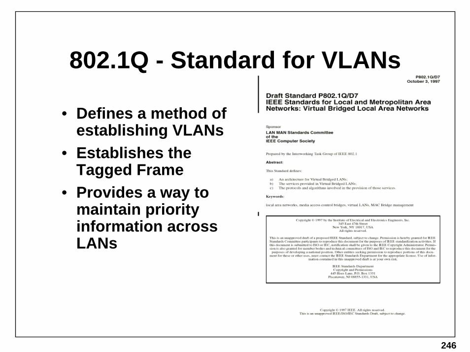
802.1Q - Standard for VLANs
• Defines a method of establishing VLANs
• Establishes the Tagged Frame
• Provides a way to maintain priority information across LANs

247
What are VLANs - Virtual Local Area Networks?• Divides switch into two or more
“virtual” switches with separate broadcast domains
• Achieved by manual configuration through the switches’ management interface
• Only that switch will be segmented

248
Multiple VLANs in One Switch
• Multiple VLANs can be defined on the same switch

249
Why VLANs?• Lots of broadcast traffic wastes bandwidth
– VLANs create separate broadcast domains» Microsoft Networking» Novell Networking» NetBEUI» IP RIP» Multicast (sometimes acts like broadcast)
• VLANs can span multiple switches and therefore create separate broadcast domains that span multiple switches
250
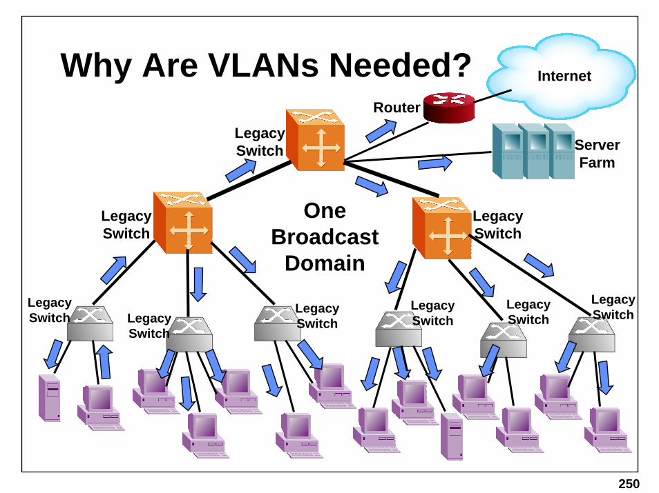
Why Are VLANs Needed?
Legacy Switch
Legacy Switch
Legacy Switch
Router
Server Farm
Internet
One Broadcast
DomainLegacy Switch Legacy
Switch
Legacy Switch
Legacy Switch
Legacy Switch
Legacy Switch

251
Possible Solution: Routers
Router
Switch
Router
Router
Server Farm
Internet
Legacy Switch Router
Router Legacy Switch Router Router

252
Router
Legacy Switch
Router
Server Farm
Internet
Legacy Switch
Legacy Switch
Possible Solution: Move Cables or Users
Legacy Switch
Legacy Switch
Legacy Switch
Legacy Switch
Legacy Switch

253
Easier Solution: VLANs
802.1Q Switch
802.1Q Switch
802.1Q Switch
Router
Server Farm
Internet
802.1Q Switch
802.1Q Switch 802.1Q
Switch
802.1Q Switch
Legacy Switch
Legacy Switch

254
More Reasons...• Link Multiplexing
– slower speed technologies share the high-bandwidth uplink– multiple IP subnets on one physical link with layer 3 switching
• Security– Without it, broadcasts are seen by everyone– Virtual private tunnel – “VPN Like” service
• Moving end-stations to different ports• Switching is faster and cheaper than routing, but
you still need full routing for some applications and to connect VLANs (IP Subnets) together

255
Standards Based VLANs
• Includes definition for a new GARP application called GVRP (GARP VLAN Registration Protocol)
– Propagate VLAN registration across the net
• Associate incoming frames with a VLAN ID• De-associate outgoing frames if necessary• Transmit associated frames between VLAN 802.1Q
compliant switches

256
Basic VLAN Concepts
• Port-based VLANs– Each port on a switch is in one and only one VLAN (except trunk links)
• Tagged Frames– VLAN ID and Priority info is inserted (4 bytes)
• Trunk Links– Allow for multiple VLANs to cross one link
• Access Links– The edge of the network, where legacy devices attach
• Hybrid Links – Combo of Trunk and Access Links
• VID– VLAN Indentifier

257
Tagged Frames
• 4 Bytes inserted after Destination and Source Address
• Tagged Protocol Identifier (TPID) = 2 Bytes (x8100)
– length/type field
• Tagged Control Information (TCI) = 2 Bytes
– contains VID

258
Trunk Link
• Attaches two VLAN switches - carries Tagged frames ONLY.

259
Trunk Links
802.1Q Switch
802.1Q Switch
Router
Server Farm
Internet
802.1Q Switch
802.1Q Switch
802.1Q Switch 802.1Q
Switch
802.1Q Switch
Legacy Switch
Legacy Switch
Trunk Links

260
Access Links
• Access Links are Untagged for VLAN unaware devices - the VLAN switch adds Tags to received frames, and removes Tags when transmitting frames.

261
Access Links
802.1Q Switch
802.1Q Switch
Router
Server Farm
Internet
802.1Q Switch
802.1Q Switch
802.1Q Switch 802.1Q
Switch
802.1Q Switch
Legacy Switch
Legacy Switch
Access Links

262
Hybrid Links
• Hybrid Links - ALL VLAN-unaware devices are in the same VLAN

263
Hybrid Links
802.1Q Switch
802.1Q Switch
Router
Server Farm
Internet
802.1Q Switch
802.1Q Switch
802.1Q Switch
Legacy Switch
802.1Q Switch
Legacy Switch
Legacy Switch
Hybrid Links
One of the PCs must support tagged frames

264
So Far So Good...• So one might ask: “what does the Bridge
table look like?”• Two answers:
– multiple (distinct) tables: one for each VLAN– one mother of all tables, with a VLAN column
• They sound similar, but it turns out they are VERY different

265
Multiple TablesEntry MAC Addr Port active
1 0800900A2580 1 yes2 002034987AB1 1 yes3 0500A1987C00 2 yes4 00503222A001 2 yes56789
101112
Entry MAC Addr Port active1 0800900A2580 1 yes2 002034987AB1 1 yes3 0500A1987C00 2 yes4 00503222A001 2 yes56789
101112
Entry MAC Addr Port active1 0800900A2580 1 yes2 002034987AB1 1 yes3 0500A1987C00 2 yes4 00503222A001 2 yes56789
101112
Entry MAC Addr Port active1 0800900A2580 1 yes2 002034987AB1 1 yes3 0500A1987C00 2 yes4 00503222A001 2 yes56789
101112
Each Table is for One VLAN
• Called MFD (multiple forwarding databases) or Independent Learning
• Each VLAN learns MAC addresses independently, so duplicate MAC addresses are OK.

266
One (Big) TableEntry MAC Addr Port active VLAN
1 0800900A2580 1 yes 22 002034987AB1 1 yes 23 0500A1987C00 2 yes 24 00503222A001 2 yes 25 080034090478 3 yes 16 049874987AB1 5 yes 17 0555A1945600 5 yes 38 00503222A023 5 yes 29
101112
• Called SFD (Single Forwarding Database) or Shared Learning
• No duplicate MAC addresses
• Asymmetric VLAN possible

267
Asymmetric VLANs (also known as “interoperability killer”)
LegacyRouter
• Legacy router can talk to legacy clients with one physical link
• Legacy clients cannot talk to each other

268
802.1Q Switch
Asymmetric VLANsLegacy Router
Legacy Server Farm
Internet
802.1Q Switch
802.1Q Switch
Legacy Switch
Access Link
A Simplified Example:
George sends broadcast message to Al through Legacy Router. (remember they can’t talk direct)
Router sends broadcast, which all devices receive.
George
Al
1
2
2
3
3
5
4
4
4
6
7
7
8
888

269
Independent Learning I
• Legacy router learns MAC addresses from both VLANs
• Requires 2 physical links

270
802.1Q Switch
Independent VLANs Legacy Router
Legacy Server Farm
Internet
802.1Q Switch
802.1Q Switch
Legacy Switch
Access Link
A Simplified Example:
George sends broadcast message to Al through Legacy Router. (remember they can’t talk direct)
Router sends broadcast, which only VLAN green receives.
George
Al
1
2
2
3
3
5
4
4
4
6
7
8

271
Independent Learning II
• VLAN-aware router only needs one physical link

272
802.1Q Switch
Independent VLANs 802.1Q Router
Legacy Server Farm
Internet
802.1Q Switch
802.1Q Switch
Legacy Switch
Trunk Link
A Simplified Example:
George sends broadcast message to Al through Legacy Router. (remember they can’t talk direct)
Router sends broadcast, which only VLAN green receives.
George
Al
1
2
2
3
3
5
4
4
4
6
7
8

273
Problems• Can’t combine SFD and MFD switches in
one network• Some switches only do one or the other,
and can’t be changed• Hybrids of SFD and MFD makes this tricky

274
Other Additions
• 802.1v: Layer 3 based VLANs– IP traffic on a different VLAN than IPX
• 802.1s: Multiple Spanning Trees (one per VLAN)
– allows for using the disabled links
• ATM to IEEE VLAN mapping – VLAN to ELAN mapping (Emulated LANs)

275
GARP (yeah, I know, “the world according to”… that’s a new one!)
• Generic Attribute Registration Protocol• Standard Defines:
– method to declare attributes to other GARP participants– frame type to convey GARP messages: Protocol Data Unit
(PDU)– rules and timers for registering/de-registering attributes
• GVRP: GARP VLAN Registration Protocol– GARP based method for VLAN info propagation
• GMRP: GARP Multicast Registration Protocol
– GARP based method for multicast group propagation

276
Windows screenshot —>
GVRP Vendors (current): Extreme, 3Com and HP
Several others are developing working implementations also.
• Industry Implementation Example– 3Com manufactures Network Interface Cards that take advantage of GVRP– Accessed via the Control Panel (DynamicAccess®)– Extremely easy to configure

277
How Do VLANs “Secure”?
802.1Q Switch
802.1Q Switch
802.1Q Switch
Router
Server Farm
Internet
802.1Q Switch
802.1Q Switch 802.1Q
Switch
802.1Q Switch
Legacy Switch
Legacy Switch
Broadcasts not seen by Green Users

278
VLAN Security
• VLAN is NOT a security mechanism, but its attributes provide some basic defenses against naïve users
• Ultimately, 802.3 and 802.1 do not provide real security – upper layers must be used to authenticate, encrypt, etc.
• Even 802.1x Network Access is not perfect either (more on that later…)

279
This page left intentionally blank.

280
This page left intentionally blank.

281
Priorities/QoS
802.1p

282
The Problem
• In a switched network, if more than one device sends packets to the same destination at the same time, the switch will buffer them and send them out based on first-in first-out basis
• So time-sensitive traffic (like voice) has no priority over other types (mail, ftp, web)
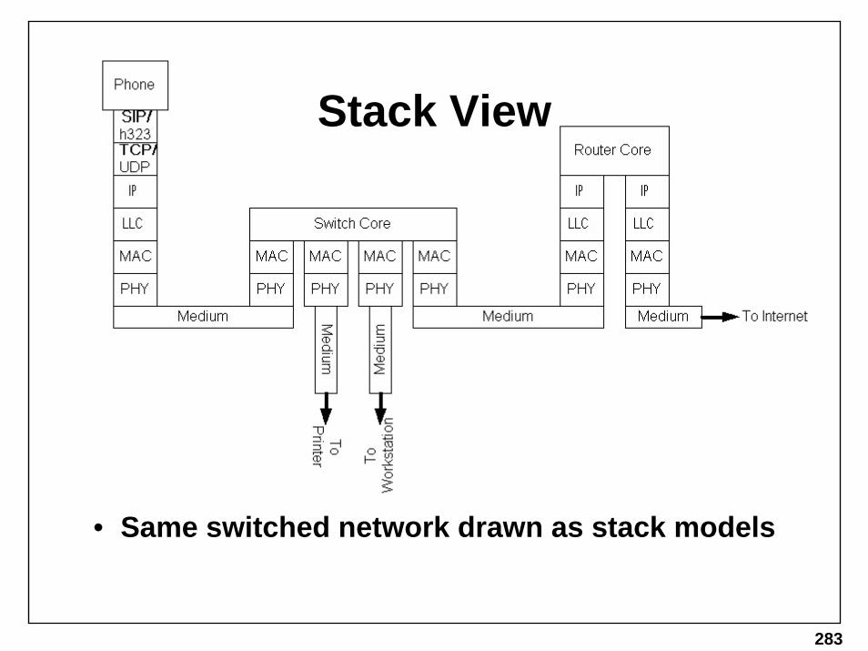
283
Stack View
• Same switched network drawn as stack models

284
Inside the SwitchThis is a verysimplistic view
• Buffers can have multiple queues for different priority traffic
• Higher-priority can be sent before lower-priority

285
Possible Solution
• Q: How does switch know which traffic to prioritize?
• Possible answer: set priority for each port inside the switch configuration...
• But then how does it tell the next switch along the path what the priority was?
• And not all traffic from the same port should be treated equally - it may come from a router, or a shared link, or another switch

286
Better Solution
• Tag the priority of each packet with its relative priority value
• Then switch can put higher-priority tagged frames in a higher-priority queue based on the value

287
Remember VLAN Tagged Frames?
• 4 Bytes inserted after Destination and Source Address
• Tagged Protocol Identifier (TPID) = 2 Bytes (x8100)
– length/type field
• Tagged Control Information (TCI) = 2 Bytes
– contains VID

288
Priority Tagged Frames
• Uses user_priority field value of 0-7 for priority numbers
• VID may be a real VLAN ID number, or the value of x000 = “Priority Tagged”, meaning not a VLAN Tagged frame (x000 is illegal VLAN value)
• Same Ethertype of x8100

289
Limitations of 802.1p
• It is NOT Quality of Service (QoS)– There is no guarantee of bandwidth, latency, nor jitter– If other devices use the same priority, no difference– If higher-priority fills the pipe constantly, lower-priority will
never get through (depending on implementation)
• It IS Class of Service (CoS)• Access to a shared ethernet
medium/network isn’t helped - it’s still under the rules of CSMA/CD

290
Example
• Even if the phone uses 802.1p tagged frames, it has to share the repeated network with the other devices with the same odds of success
• Once its frames get to the switch, then they will be sent through faster and with better odds than frames from other devices

291
This page left intentionally blank.

292
This page left intentionally blank.

293
Layer-3 Switching

294
Routing vs. Switching
• Routing is done at layer 3 (IP layer), thereby connecting IP subnets
• Switching is done at layer 2 (MAC layer), thereby connecting Ethernet LAN segments
• Routing is slow because it’s done in software
• Switching is fast because it’s done in hardware
• So why not Route in hardware?

295
Routing in Hardware
• Put forwarding engine into hardware, leave routing protocols/database in software
• Remove unnecessary or seldom-used protocols (IPX, Appletalk, etc.)
• Don’t route to non-Ethernet technologies (Token Ring, FDDI, Frame Relay, ATM, etc.)
• Lose advanced functions (statefull firewall, NAT, IP header compression, etc.)

296
Stack View
Remember this?

297
Layer-3 Switch Stack View

298
Layer-3 Switch Implementations
• Actual implementations vary depending on architecture
• Most have fast-forwarding engines per blade which can forward based on IP Address
• Usually, there is one or more central CPUs to handle exception cases, routing updates and management
• Some L3 Switches now offer advanced features:– filtering based on address, ports, etc.– IP multicast in the fast path– IPX, Appletalk, etc.– Advanced routing protocols such as BGP

299
This page left intentionally blank.

300
This page left intentionally blank.

301
MPLS over Ethernet

302
The Problem
• Today’s Internet Core isn’t scaling rapidly enough
• Traffic is doubling every 6 - 12 months• Bandwidth consumption is not balanced
across all possible paths (unless ECMP is used)
• All traffic traverses the shortest path without regard to QoS
• ATM switches in the core create a two-layer problem of ATM switching vs. IP routing

303
The Solution
• MPLS defines a method of switching packets by exchanging labels at each hop
• A router in the MPLS context is called a LSR (Label Switching Router)
• A Traffic engineered MPLS tunnel is a series of label switched hops (LSH) collectively called an LSP(Label Switched Path)
• The Tunnel is constructed by the Ingress LSR
• LSPs created with Label Distribution Protocol (LDP) are bounded by a pair of participating LSRs, the data plane topology is identical to IP hop by hop

304
Shortcut Routing
BGPSubscriber
ISP 3
SubscriberISP 2
D F
Incoming TransitTraffic
BGP
BGP
BGP
SubscriberISP 1
G
BackboneProvider
Short Cut Tunnel 2
H
I
J
Router G's Next HopFor Routes in ISP 3
Router K's NextHop For Routes inISP 1
Router E's Next HopFor Routes in ISP 2
E
B
K
CShort Cut Tunnel 1
A
Shortest Path toISPs 1, 2, 3, and 4
Forwarding TableDestination Next HopPrefixes in ISP 1 LSP 1Prefixes in ISP 2 Router BPrefixes in ISP 3 LSP 2Prefixes in ISP 4 LSP 2
INGRESSLSR
SubscriberISP 4
MRouter G's Next HopFor Routes in ISP 4
EGRESSLSR
EGRESSLSR

305
MPLS Encoding• MPLS uses a 32 bit “Shim Header”
– The Header is pushed onto the IP packet by the Ingress LSR– The Header is popped off by the Egress LSR or Penultimate LSR– Labels can be STACKED!
Data Link LayerLayer 2 Header
MPLS ShimHeader
IP HeaderLayer 3 Packet Data
Label20 bits
EXP3 bit
S1 bit
Time To Live8 bits
32 Bits
The Label Field is self explanatoryThe EXP Field is "Experimental" though it is proposed use is to inidicate Per Hop Behavior of labeledpackets traversing Label Switching RoutersThe Stack (S) Field indicates the presence of a label stackThe Time to Live Field is decremented at each LSR hop and is used to throw away looping packets

306
MPLS over Ethernet
• MPLS header adds 5 Bytes (as opposed to VLAN which adds 4)
– There can be more than 1 MPLS header– Therefore, your GigE equipment must support more than
1518 bytes if you want MPLS to cross it (I.e., you use it in the core)
• MPLS is NOT VLANs– VLANs define a broadcast domain, MPLS defines an LSP
tunnel– A broadcast packet with an MPLS label will still be
broadcast to everyone (although MPLS packets never need broadcasting)

307
Ethernet over MPLS
• Because MPLS defines an end-to-end labeled tunnel, it’s very useful for creating VPNs
• The ISP can create VPNs between Enterprise/corporate regional offices
– For internal VoIP calls– For internal data exchange– For intranet apps
• The Carrier can create VPNs between ISP POPs
– To simulate a leased long-haul backbone– So the ISP can offer Enterprise VPNs– As a backup backbone or to offload bandwidth

308
Virtual Leased Line
Last Mile
DA SA Etype PayloadSA*0x8847DA* L1
DA SA Etype PayloadDA SA Etype Payload
DA SA EtypePayloadDA’SA’ 0x8847 L2 L1
Provider’s MPLS Backbone
CPE
CPE
CPE
CPE
LER
LERLSR LSR
LER
LER
DA SA Etype PayloadSA”0x8847DA” L2’L1
Last Mile POPPOP

309
Transparent LAN Service
Provider’s MPLS Backbone
Last Mile
CPE
CPE
CPE
CPE
LER
LERLSR LSR
LER
LERLast Mile
CPE
LER LER
LSR
Customer A
Customer B
San Francisco POP New York POP
Chicago POP
VLAN Tunnel LSPEthernet VC LSP

310
This page left intentionally blank.

311
This page left intentionally blank.

312
This page left intentionally blank.

313
Link Aggregation
802.3ad

314
Basic Concept• Originally only one of
many separate physical links could be used (else loops)
• Spanning tree used to disable all but one
• Did provide redundancy, but not efficient use of links

315
Enter Trunking
• Multiple physical links joined into one logical link
• Only one MAC address used for trunk group
• All links in same group must be same speed and full-duplex

316
Proprietary Methods
• Very popular with users, but proprietary• EtherChannel, Fast EtherChannel, Gig
– Cisco’s protocol (routers, switches)– Also licensed by Adaptec, Intel, Compaq, Sun, HP, ZNYX,
Phobos, Auspex (all NICs)
• MultiLink Trunking (MLT)– Nortel’s protocol (switches)
• Virtual Link Trunking (VLT)– 3Com’s protocol (switches)

317
802.3ad - Link Aggregation• Study group started in
November 1997 – Standard completed last year (2000)
• website: http://grouper.ieee.org/groups/802/3/ad/

318
Benefits and Goals• Increased Bandwidth (duh)• Incremental bandwidth increases - smaller jumps than 10 to 100
to 1000 - not perfect scaling, but better than one link’s worth• Failure protection/redundancy (maybe)• Automatic configuration - if it can aggregate, it will• Rapid reconfiguration• Deterministic behavior - configuration will not be dependent on
the order in which events occurred• NOTE: some of these goals are inconsistent (see later)

319
Layers Involved
• IEEE Standard - adds to 802.3 CSMA/CD Standard• Works with 10/100/1000 - portable to other MACs

320
Layers Involved (cont.)• MAC Client is Bridge layer,
LLC, etc.• MAC Control (optional) is for
Flow control (802.3x)• MAC is CSMA/CD, CRC32,
Frame Encapsulation
This means Inter-Packet Gap and encapsulation is enforced by the individual link MACs (called physical MACs), but FCS and source MAC address can be sent from the single MAC above (e.g., if relayed)No CSMA/CD since full-duplex required for link aggregationNotice the split happens at the traditional software layer, so changes need only be done in software (usually)Flow control operates independent of the aggregation - it could pause link aggregation control frames (this is good, me thinks)

321
Spanning Tree• Assume redundant link on
right is a trunk group• Spanning Tree sees one
logical link (because it operates above the LA sublayer)
So Spanning Tree would disable the link - thus all physical links disabledThis is a bad example because it’s impossible for a bridge to be trunk linked to a shared medium (gotcha!)

322
Quick Overview
• Ports constantly send out packets• When one or more cables are linked, they
auto-configure an aggregate group link • (yes, I do mean one or more)• Once aggregated, they still send each other
packets as a keep-alive

323
How it works (or doesn’t)
• The 3 physical links above are grouped together automatically or through configuration to be one logical link
• The green user on the right sends frames to the red user
Frame 8Frame 2
Frame 5
Frame 1
Frame 3
Frame 4
Frame 7
Frame 6
Each frame is NOT broken up/spread across the wires (we’re still stuck with a normal MAC, after all)Instead, they are each sent whole - on one wire.Also, we CANNOT send one frame on one wire, another on a second wire, etc. (the way shown above) Why not?Because they could arrive out of order - that would be BAD.
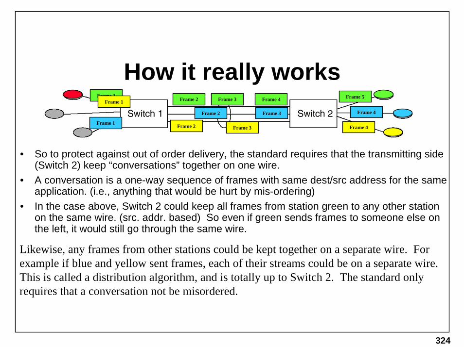
324
How it really worksFrame 2 Frame 5Frame 1
Frame 3 Frame 4Frame 1
Frame 1
Frame 2
Frame 2
Frame 3
Frame 3 Frame 4
Frame 4
• So to protect against out of order delivery, the standard requires that the transmitting side (Switch 2) keep “conversations” together on one wire.
• A conversation is a one-way sequence of frames with same dest/src address for the same application. (i.e., anything that would be hurt by mis-ordering)
• In the case above, Switch 2 could keep all frames from station green to any other station on the same wire. (src. addr. based) So even if green sends frames to someone else on the left, it would still go through the same wire.
Likewise, any frames from other stations could be kept together on a separate wire. For example if blue and yellow sent frames, each of their streams could be on a separate wire. This is called a distribution algorithm, and is totally up to Switch 2. The standard only requires that a conversation not be misordered.

325
Reference Topologies• Notice that repeaters
cannot participate• Each trunk link is one MAC
layer to one MAC layer.• All the trunks are MAC-to-
MAC, but network A is many MAC addresses to many others, whereas B and C are many to one, and D and E are one to one. Thus the distribution algorithms will be different for them: based on src. addr., src & dest, src & dest& type, etc.

326
LACPDU • Link Aggregation Control (LAC) entities
send each other configuration info using LACPDUs (LAC Protocol Data Units)
• The destination address of the LACPDU is a well-known multicast address
• If the link partner doesn’t support LA, then it discards them (doesn’t forward)
• Repeaters forward them like normal frames (remember, repeaters are layer 1 - they don’t even know what a “frame” is!) - BUT if there’s a repeater, then the link should be half-duplex and thus non-aggregatable (is that a word?)

327
Destination Address
• LACPDU Destination Address is a multicast of the type not forwarded by bridges (even if they don’t know what it’s for, they won’t forward it)

328
Some Background on Selection
• Wanted auto-config to avoid user mistakes, as well as be flexible
• For instance, when the user crosses wires from 2 systems (shown left)
• By using a System ID Key, this can be detected and fixed

329
More Goals
• Can also detect loopbacks and disable ports
• Plus need Port ID Keys to detect which ports can be aggregated together
• So for two systems A and B with ports 1 and 2, we call it {A1,B2}

330
One more set of Keys• For manual config, and
alernative selection algorithms, the Aggregators need a Key
• This way the Agg Group MAC address can be assigned to the ports
• Port selects Agg with same Key as itself
• This Key is internal -not transmitted - only port key and sys ID transmitted

331
Selection Logic• IEEE wanted differing implementations of selection, as long as the
following are kept:– Each port assigned a Key - ports that can agg together have the same key - else
unique Key– Each Aggregator assigned a Key and MAC address– Ports only select Aggs with same Key– Ports in the same LAG use the same Aggregator– Individual ports each have their own Agg– If a port can’t select an Agg due to rules above, then it can’t be attached to one– MAC Client won’t see the port until it’s selected and attached
• That’s it. This leaves a lot open.

332
Default Selection Operation• When multiple ports
in an aggregation, select the lowest number Aggregator of the ports in the aggregation
• That port may be just selected but not attached
This algorithm has a flaw - can you see it?

333
Problems
• Not necessarily deterministic• If deterministic, then a failover can take the
net down for a LONG time (due to spanning tree)
• A few too many options for users• Doesn’t support full-duplex repeaters (yes,
there is a such a thing)

334
This page left intentionally blank.

335
This page left intentionally blank.

336
This page left intentionally blank.

337
Multiple Spanning Trees802.1s

338
Multiple Spanning Trees
• If multiple VLANs are run on a network, they all run on the same spanning tree
• This means unused (blocked) links don’t carry any traffic
• But traffic from separate VLANs can be sent on different spanning trees, thereby utilizing the blocked ports
• So now one can assign VLANs to separate spanning trees
• (This is NOT trivial to actually deploy)

339
Rapid Reconfiguration802.1w

340
Rapid Reconfiguration
• A broken spanning tree can take 50 seconds to re-converge
• A new algorithm, using new BPDU frames, can decrease the time down to 10 milliseconds (best case)
• It’s backwards compatible with legacy 802.1D bridges (they won’t converge faster, but they will work)

341
Port Based Network Access802.1X

342
LAN Security
• Anyone can connect their notebook/PC to a switch and use/snoop the network
• 802.1x provides a method whereby the switch only allows the user to contact a RADIUS server with EAP packets to be authenticated
• Once authenticated the user will be able to access the net
• This is NOT fool-proof, but good enough for hotels, libraries, etc. (not good enough for the government)

343
Resilient Packet Rings802.17

344
Resilient Packet Rings
• In a SONET ring, half of the fiber is never used for real traffic – this is a waste of possible bandwidth – better to use both rings
• Currently, several vendors (Cisco, Nortel, Lucent) have proprietary methods
• There’s still debate about the need for the standard, but they’re trying to move forward – working group 802.17

345
RPR Applications

346
RPR’s Goal
• Reuse as much of Ethernet as possible– Frame format (mostly)– Physical speeds (the higher ones)– Marketing name power (definitely)
• Connect in a ring topology like SONET & FDDI
• Have a fast SONET-like protection fail-over• Apply QoS from upper layers to Layer 2
– Similar to 802.1p but for media access as well– Possible changes/additions to IP to make use of it (yes,
that sounds incredibly stupid, but there are people pushing for this)
• Create more work for people

347
This page left intentionally blank.

348
This page left intentionally blank.

349
Ethernet in the First Mile802.3ah

350
EFM
• VERY early stages – had 2 meetings so far• Basic idea is delivering Ethernet to the local
loop for FTTH, FTTC, FTTB markets• Currently multiple vendor options for Multi-
Tenant Units (MTU) • Easy problem: getting industry interest
(100-150 people at each meeting so far)• Hard problems: determining the business
models and market direction for the application

351
EFM Work
• Fiber Loop– Basic Gig Ethernet from CO to switch in the field out to
CPE, like a bigger LAN – only needs some missing pieces
» Adds 1Gig over single-fiber (bi-directional) for 10km
– PONs (Passive Optical Networks) using passive splitters
• Copper Loop– At 10mbps for <750m– Replace DSL MAC layer with Ethernet but use same
PHY (thus, copper loop)• Specify OAM
– Remote failure, loopback, and link monitoring

352
First Mile Copper

353
PONs
• Passive Optical fiber plant, based on splitters• Logically equivalent to Cable TV (HFC) plant• MAC access protocol like DOCSIS over fiber – broadcast down from
headend, upstream is TDM-like (requested slots of varying length)• APON: ATM version, standardized by ITU and FSAN but no interop• EPON: Ethernet frame version

354
This page left intentionally blank.

355
This page left intentionally blank.

356
This page left intentionally blank.

357
Wrap-Up

358
The Future

359
Acknowledgements
• Some of the slides, drawings, and animations were stolen borrowed from:
– Gerry Nadeau– Benjamin Schultz– Adam Healey– Rupert Dance– Gary Pressler– Eric Lynskey– The IEEE standards and website

360
Websites• To get the most recent version of this presentation,
wait 1 week, then go to: http://www.iol.unh.edu/training/ethernet.html
• IEEE website: http://grouper.ieee.org/groups/802• IETF website: http://www.ietf.org• 10 Gigabit Ethernet Alliance: http://www.10gea.org• My email address:

361
Acronym Expansion•• ARP ARP –– Address Resolution Protocol Address Resolution Protocol –– the protocol used to discover a the protocol used to discover a
device’s Ethernet address based on its IP addressdevice’s Ethernet address based on its IP address•• ATM ATM -- Asynchronous Transfer Mode Asynchronous Transfer Mode –– the Broadbandthe Broadband--ISDN protocol based ISDN protocol based
on circuits and cell switched communications. on circuits and cell switched communications. •• AUI AUI –– Attachment Unit InterfaceAttachment Unit Interface•• BPDU BPDU –– Bridge Protocol Data UnitBridge Protocol Data Unit•• CIR CIR –– Committed Information Rate Committed Information Rate –– the bandwidth level/rate for Frame the bandwidth level/rate for Frame
Relay circuits which the user has agreement to transmit forRelay circuits which the user has agreement to transmit for•• CoSCoS –– Class of ServiceClass of Service•• CRC CRC –– Cyclical Redundancy Check Cyclical Redundancy Check –– a 4a 4--byte value produced from a byte value produced from a
polynomial function, used to validate the integrity of the contepolynomial function, used to validate the integrity of the contents of the nts of the frame (like a parity check, or checksum)frame (like a parity check, or checksum)
•• CSMA/CD CSMA/CD –– Carrier Sense, Multiple Access with Collision Detection Carrier Sense, Multiple Access with Collision Detection –– the the name and description of the halfname and description of the half--duplex protocol used to access the duplex protocol used to access the network in an Ethernet networknetwork in an Ethernet network
•• CWDM CWDM –– Coarse Wavelength Division Multiplexing Coarse Wavelength Division Multiplexing –– a method of sending a method of sending multiple independent signals on the same fiber by sending them amultiple independent signals on the same fiber by sending them at different t different wavelengths (colors) wavelengths (colors) –– the Coarse version of WDM usually implies very few the Coarse version of WDM usually implies very few wavelengths are used (6 or less) and they may not be in the samewavelengths are used (6 or less) and they may not be in the same bandband
•• DIX DIX –– Digital, Intel, and Xerox Digital, Intel, and Xerox –– the three companies that produced the three companies that produced interoperable Ethernet products before moving into an 802.3 workinteroperable Ethernet products before moving into an 802.3 working group ing group to become a standardto become a standard
•• DMD DMD –– Differential Modal DelayDifferential Modal Delay•• DOCSIS DOCSIS –– Data over Cable System Interface Specification Data over Cable System Interface Specification –– the industry the industry
standard for data communications over cable TV systemsstandard for data communications over cable TV systems

362
Acronym ExpansionAcronym Expansion
•• DSCP DSCP –– DiffServDiffServ Code Point Code Point –– the binary value field in the IP packet to mark the binary value field in the IP packet to mark a packet with a particular pera packet with a particular per--hop behavior (PHB) forhop behavior (PHB) for QoSQoS parametersparameters
•• DTE DTE –– Data Terminal Equipment Data Terminal Equipment •• DWDM DWDM –– Dense Wavelength Division Multiplexing Dense Wavelength Division Multiplexing –– a method of sending a method of sending
multiple independent signals on the same fiber by sending them amultiple independent signals on the same fiber by sending them at different t different wavelengths (colors) wavelengths (colors) –– the Dense version of WDM usually implies all of the the Dense version of WDM usually implies all of the more than 8 wavelengths are within a fixed narrow bandmore than 8 wavelengths are within a fixed narrow band
•• FEXT FEXT –– Far End CrosstalkFar End Crosstalk•• FR FR -- Frame Relay Frame Relay -- A packetA packet--switched method of data communication switched method of data communication
(similar to, but more efficient than, the original X.25 WAN prot(similar to, but more efficient than, the original X.25 WAN protocol) provided ocol) provided by telecommunications carriers and Internet service providers (Iby telecommunications carriers and Internet service providers (ISPs). Frame SPs). Frame Relay can provide guaranteed bandwidth at no additional charge iRelay can provide guaranteed bandwidth at no additional charge if the lines f the lines are “open” during periods of low traffic. Frame Relay can run atare “open” during periods of low traffic. Frame Relay can run at speeds of speeds of 36 Kbps to 2 Mbps. It is now enjoying high popularity as a reaso36 Kbps to 2 Mbps. It is now enjoying high popularity as a reasonably priced nably priced alternative to leased line service.alternative to leased line service.
•• FRF FRF –– Frame Relay Forum Frame Relay Forum –– the industry forum that coordinates and the industry forum that coordinates and advances standards for Frame Relay.advances standards for Frame Relay.
•• FCS FCS –– Frame Check SequenceFrame Check Sequence•• GARP GARP –– Generic Attribute Registration ProtocolGeneric Attribute Registration Protocol•• GMRP GMRP –– Generic Multicast Registration ProtocolGeneric Multicast Registration Protocol•• GMII GMII –– Gigabit Media Independent InterfaceGigabit Media Independent Interface•• GVRP GVRP –– Generic VLAN Registration ProtocolGeneric VLAN Registration Protocol

363
Acronym ExpansionAcronym Expansion•• IEEE IEEE –– Institute for Electrical and Electronics Engineers Institute for Electrical and Electronics Engineers –– the standards body that the standards body that
defines electrical standards, including the 802 LAN/WAN committedefines electrical standards, including the 802 LAN/WAN committee which defines e which defines such protocols as Ethernet and Token Ring.such protocols as Ethernet and Token Ring.
•• IETF IETF –– Internet Engineering Task Force Internet Engineering Task Force –– the standards body that defines protocols for the standards body that defines protocols for the Internet.the Internet.
•• IP IP -- Internet Protocol Internet Protocol -- The communication protocol of the Internet. (version 4 is the The communication protocol of the Internet. (version 4 is the current version)current version)
•• IPv6 IPv6 –– IP version 6 IP version 6 –– the heir apparent for the current IP version 4 the heir apparent for the current IP version 4 –– version 6 adds a version 6 adds a much larger address space, security, automuch larger address space, security, auto--configuration, andconfiguration, and anycastinganycasting
•• IPG IPG –– InterInter--Packet Gap Packet Gap –– the idle period between packets, defined as minimally 96 bit the idle period between packets, defined as minimally 96 bit timestimes
•• ISDN ISDN -- Integrated Services Digital Network Integrated Services Digital Network -- Allows for endAllows for end--toto--end digital transfer of end digital transfer of voice and data. ISDN, used primarily by small offices, home offivoice and data. ISDN, used primarily by small offices, home offices, and individual ces, and individual households, combines digital switching and digital transmission households, combines digital switching and digital transmission and offers higher and offers higher bandwidths than current analog modems.bandwidths than current analog modems.
•• ISP ISP -- Internet Service Provider Internet Service Provider -- A service company that provides customers access to A service company that provides customers access to the Internet.the Internet.
•• ITU ITU –– International Telecommunications Union International Telecommunications Union –– (formerly the CCITT) the standards (formerly the CCITT) the standards body that defines many international standards, including the phbody that defines many international standards, including the phone system.one system.
•• LLC LLC –– Logical Link ControlLogical Link Control•• LTP LTP –– Link Test Pulse Link Test Pulse •• MAC MAC –– Media Access Control Media Access Control –– The layer of the 802.3 stack above the Physical below The layer of the 802.3 stack above the Physical below
the Logical Link layer the Logical Link layer –– the MAC is responsible for encapsulating/the MAC is responsible for encapsulating/decapsulatingdecapsulating the the packet with Ethernet fields, accessing the medium (either in halpacket with Ethernet fields, accessing the medium (either in halff--duplex or fullduplex or full--duplex duplex mode), and padding or removing the pad on receipt.mode), and padding or removing the pad on receipt.

364
Acronym ExpansionAcronym Expansion
•• MAU MAU –– Medium Attachment UnitMedium Attachment Unit•• MDI MDI –– Media Dependent InterfaceMedia Dependent Interface•• MFD MFD –– Multiple Forwarding Database Multiple Forwarding Database –– a bridge that supports independent a bridge that supports independent
learning, using a separate bridge table for each VLANlearning, using a separate bridge table for each VLAN•• MII MII –– Media Independent Interface Media Independent Interface –– the interface between the Physical and the interface between the Physical and
MAC layers MAC layers –– it can be a physically exposed interface allowing the user to it can be a physically exposed interface allowing the user to replace the transceiver (e.g., to use a fiber transceiver insteareplace the transceiver (e.g., to use a fiber transceiver instead of copper)d of copper)
•• MMF MMF –– MultiMulti--Mode FiberMode Fiber•• MPLS MPLS -- MultiMulti--Protocol Label Switching Protocol Label Switching –– an IETF standard for assigning tags an IETF standard for assigning tags
toto multiprotocolmultiprotocol frames for transport across packet or cellframes for transport across packet or cell--based networks. based networks. It is based on the concept of label swapping, in which units of It is based on the concept of label swapping, in which units of data (e.g., a data (e.g., a packet or a cell) carry a short, fixedpacket or a cell) carry a short, fixed--length label that tells switching nodes length label that tells switching nodes how to process the data.how to process the data.
•• NAT NAT –– Network Address Translation Network Address Translation –– the method whereby fake/illegal IP the method whereby fake/illegal IP addresses are used inside a user’s network and are translated toaddresses are used inside a user’s network and are translated to a real a real address on the public side of the NAT router/gateway. Also someaddress on the public side of the NAT router/gateway. Also sometimes times called NAPT for Network Address and Port Translators because thecalled NAPT for Network Address and Port Translators because they y translate both addresses and TCP/UDP ports.translate both addresses and TCP/UDP ports.
•• NEXT NEXT –– Near End CrosstalkNear End Crosstalk•• NIC NIC –– Network Interface CardNetwork Interface Card•• OCOC--3/12/48/192 3/12/48/192 -- Optical Carrier Levels 3, 12, 48, and 192. SONET Optical Carrier Levels 3, 12, 48, and 192. SONET
(Synchronous Optical Network) line interfaces/rates based on mul(Synchronous Optical Network) line interfaces/rates based on multiples of tiples of OC1 at 51.84mbps, so OCOC1 at 51.84mbps, so OC--3 would be 155.52mbps.3 would be 155.52mbps.

365
Acronym ExpansionAcronym Expansion
•• OSI OSI -- Open Systems Interconnection (Model) Open Systems Interconnection (Model) -- An international set of rules An international set of rules for computer networking that creates open standards to allow a cfor computer networking that creates open standards to allow a computer omputer on any network to shareon any network to share iformationiformation with any other computer on that network with any other computer on that network or a connected network. The OSI model is divided into seven layeor a connected network. The OSI model is divided into seven layers based rs based on the function and intelligence of the transmission equipment ion the function and intelligence of the transmission equipment involved. nvolved.
•• PCS PCS –– Physical CodingPhysical Coding SublayerSublayer –– a layer within the PHY that a layer within the PHY that encodes/decodes theencodes/decodes the bitstream bitstream
•• PHY PHY –– Physical Layer Physical Layer –– the layer between the MAC layer and transmission the layer between the MAC layer and transmission medium (cable)medium (cable)
•• PMA PMA –– Physical Medium AttachmentPhysical Medium Attachment•• PMD PMD –– Physical Medium Dependent Physical Medium Dependent –– the lowest layer of the Physical layer the lowest layer of the Physical layer
that attaches to the transmission mediumthat attaches to the transmission medium•• PON PON –– Passive Optical NetworkPassive Optical Network•• QoSQoS –– Quality of ServiceQuality of Service•• RS RS –– ReconciliationReconciliation SublayerSublayer•• RSVP RSVP –– ResourceResource reSerVationreSerVation Protocol Protocol –– the protocol used for reserving the protocol used for reserving
bandwidth for a particular flow.bandwidth for a particular flow.•• RTP RTP –– RealReal--time Transport Protocol time Transport Protocol –– the IETF standard for a lightthe IETF standard for a light--weight, weight,
sequenced, transport protocol to carry timesequenced, transport protocol to carry time--sensitive data.sensitive data.•• RTCP RTCP –– RealReal--time Transport Control Protocol time Transport Control Protocol –– a control protocol for RTP a control protocol for RTP
streamsstreams

366
Acronym ExpansionAcronym Expansion
•• SDH SDH -- Synchronous Digital Hierarchy Synchronous Digital Hierarchy -- The European version of the SONET The European version of the SONET standard with two major differences: (1) the terminology and (2)standard with two major differences: (1) the terminology and (2) the basic the basic line rate in SDH is equivalent to that of the SONET OCline rate in SDH is equivalent to that of the SONET OC--3/STS3/STS--3 rate (i.e., 3 rate (i.e., 155.52 Mbps). SDH is the ITU standard for high155.52 Mbps). SDH is the ITU standard for high--capacity optical capacity optical transmission.transmission.
•• SFD (1) SFD (1) –– Start Frame Delimiter Start Frame Delimiter –– the byte after the 7 byte preamble used to the byte after the 7 byte preamble used to indicate the beginning of the MAC frameindicate the beginning of the MAC frame
•• SFD (2) SFD (2) –– Single Forwarding Database Single Forwarding Database –– a bridge that supports shared a bridge that supports shared learning, using the same bridge table for every VLANlearning, using the same bridge table for every VLAN
•• SMF SMF –– SingleSingle--Mode FiberMode Fiber•• SNMP SNMP -- Simple Network Management Protocol Simple Network Management Protocol -- A protocol used in the A protocol used in the
development of network management S. It is used to report on thedevelopment of network management S. It is used to report on the status of status of a network and the devices attached to it. a network and the devices attached to it.
•• SOHO SOHO -- Small office/home office. Small office/home office. •• SONET SONET -- Synchronous Optical Network Synchronous Optical Network -- A transmission technology based A transmission technology based
on overlaying a synchronous multiplexed signal onto a light streon overlaying a synchronous multiplexed signal onto a light stream am transmitted over fibertransmitted over fiber--optic cable. SONET is the ANSI standard for optic cable. SONET is the ANSI standard for transmitting digital information over optical networks. Fibertransmitting digital information over optical networks. Fiber--optic optic transmission rates range from 51.84 Mbps to 10transmission rates range from 51.84 Mbps to 10 GbpsGbps. SONET defines a . SONET defines a physical interface, optical line rates, frame formats, and an OAphysical interface, optical line rates, frame formats, and an OAM&P M&P protocol. The base rate is known as OCprotocol. The base rate is known as OC--1 and runs at 51.84 Mbps. Higher 1 and runs at 51.84 Mbps. Higher rates are multiples of 51.84 Mbps.rates are multiples of 51.84 Mbps.
•• TDM TDM -- Time Division Multiplexing Time Division Multiplexing -- An electrical multiplexing technique for An electrical multiplexing technique for transmitting a number of separate data, voice, and/or video signtransmitting a number of separate data, voice, and/or video signals als simultaneously over one communications medium by quickly interlesimultaneously over one communications medium by quickly interleaving a aving a piece of each signal one after the otherpiece of each signal one after the other

367
Acronym ExpansionAcronym Expansion
•• TCP TCP -- Transmission Control Protocol Transmission Control Protocol –– the reliable, connectionthe reliable, connection--oriented oriented protocol for transporting data.protocol for transporting data.
•• UDP UDP –– User Datagram Protocol User Datagram Protocol –– the unreliable, connectionless protocol for the unreliable, connectionless protocol for carrying data.carrying data.
•• UTP UTP –– Unshielded Twisted PairUnshielded Twisted Pair•• VID VID –– VLAN ID VLAN ID –– the VLAN numberthe VLAN number•• VLAN VLAN –– Virtual Local Area Network Virtual Local Area Network –– a method whereby the Layera method whereby the Layer--2 2
broadcast domain is broken up into multiple broadcast domains, bbroadcast domain is broken up into multiple broadcast domains, by y assigning some ports on switches to be in the same “VLAN” as othassigning some ports on switches to be in the same “VLAN” as other ports. er ports. This limits those ports to only be able to communicate (at layerThis limits those ports to only be able to communicate (at layer 2) with 2) with others of the same VLAN (i.e., it requires a router to pass trafothers of the same VLAN (i.e., it requires a router to pass traffic between fic between differentdifferent VLANsVLANs).).
•• VoIPVoIP –– Voice over IP Voice over IP –– providing voice service over an IP data network providing voice service over an IP data network instead of the traditional TDMinstead of the traditional TDM--based method.based method.
•• VPN VPN –– Virtual Private NetworkVirtual Private Network•• X.25 X.25 -- A standard (the standard’s document number is X.25) for handlinA standard (the standard’s document number is X.25) for handling g
data in a packetdata in a packet--switched network (the predecessor to Frame Relay) that switched network (the predecessor to Frame Relay) that uses a virtual circuit to establish a connection between a sendeuses a virtual circuit to establish a connection between a sender and a r and a receiver. Transmission in an X.25 network ranges from 9.6 Kbps treceiver. Transmission in an X.25 network ranges from 9.6 Kbps to 64 Kbps o 64 Kbps and operates on levels 1, 2, and 3 of the OSI model.and operates on levels 1, 2, and 3 of the OSI model.