Shielding calculation for ESS accelerator Lali Tchelidze TAC meeting April 2, 2014.
The ESS
Accelerator LINAC 2012
Mats Lindroos
Head of ESS
Accelerator Division
and projects

ESS
2 Guillaume
Devanz Sebastien
Bousson
Santo
Gammino
Søren Pape
Møller
Roger
Ruber
17 Partners today
Investment: 1478 M€ / ~10y
Operations: 106 M€ / y
Decomm. : 346 M€
(Prices per 2008-01-
01)
Facility for the search of new
states of matter (ie new
materials)
Proposals for nEDM, muons,
neutrino physics are being
studied
5 MW long pulse source:
-2.86 ms, 50 mA pulse
current, 14 Hz
-Protons (H+)
-High availability, >95%
-First neutrons 2019 with 7
instruments and completion
2025 with 22 instruments at
5 MW operation

Neutrons are beautiful…
..see inside materials
..see light atoms
..see isotopes ..see atoms move
..see magnetic atoms
Courtesy of Ian S. Anderson
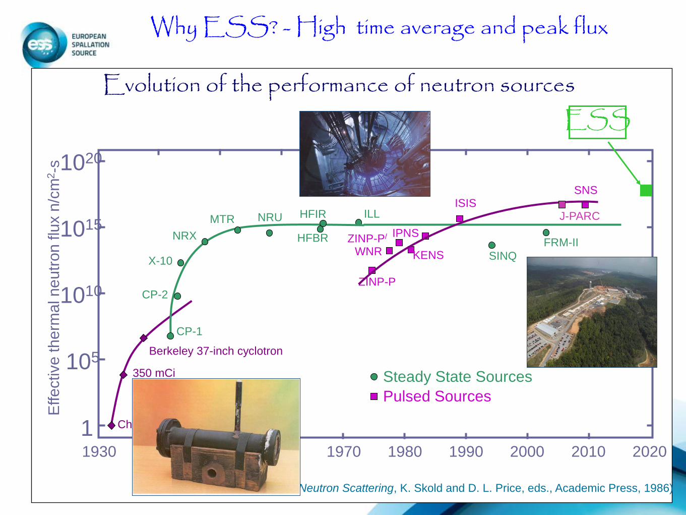
Berkeley 37-inch cyclotron
350 mCi
Ra-Be source
Chadwick
1930 1970 1980 1990 2000 2010 2020
105
1010
1015
1020
1
ISIS
Pulsed Sources
ZINP-P
ZINP-P/
KENS WNR
IPNS
ILL
X-10
CP-2
Steady State Sources
HFBR
HFIR NRU MTR
NRX
CP-1
1940 1950 1960
Effective therm
al ne
utr
on flu
x n
/cm
2-s
(Updated from Neutron Scattering, K. Skold and D. L. Price, eds., Academic Press, 1986)
Evolution of the performance of neutron sources
FRM-II
SINQ
SNS
Why ESS? - High time average and peak flux
ESS
J-PARC

Data Management
ESS AB Board
CEO C. Carlile
Accelerator Target Conventional
Facilities Instruments
Administration Director
Machine Director
Science Director
Steering Comm (STC)
Adm Financial
Comm
Programme Director
Programmme Office
Science Adv. Comm Technology Adv. Comm
Preconstruction
Construction
Operation Phase
Collaboration Partners
Neutron
Science
ESS Programme Organisation
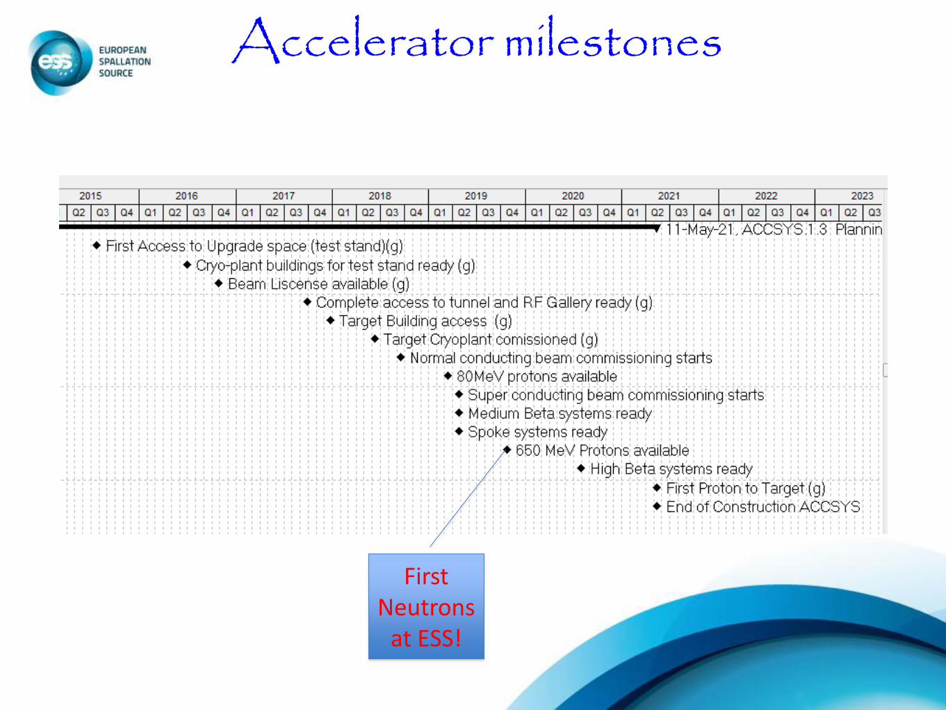
Accelerator milestones
First Neutrons
at ESS!
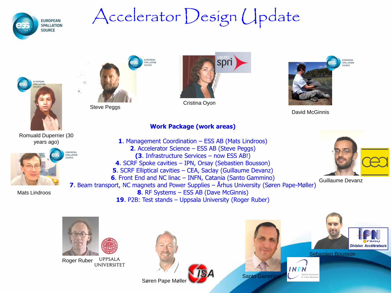
Accelerator Design Update
Work Package (work areas)
1. Management Coordination – ESS AB (Mats Lindroos) 2. Accelerator Science – ESS AB (Steve Peggs)
(3. Infrastructure Services – now ESS AB!) 4. SCRF Spoke cavities – IPN, Orsay (Sebastien Bousson)
5. SCRF Elliptical cavities – CEA, Saclay (Guillaume Devanz) 6. Front End and NC linac – INFN, Catania (Santo Gammino)
7. Beam transport, NC magnets and Power Supplies – Århus University (Søren Pape-Møller) 8. RF Systems – ESS AB (Dave McGinnis)
19. P2B: Test stands – Uppsala University (Roger Ruber)
Guillaume Devanz
Sebastien Bousson
Søren Pape Møller
Roger Ruber
Romuald Duperrier (30
years ago)
Steve Peggs Cristina Oyon
Mats Lindroos
Santo Gammino
David McGinnis

LINAC layout
8

Beam-dynamics laws and rules-of-thumb Transverse phase advance < 90 deg/cell Longitudinal phase advance below transverse phase advance Smooth change of phase advances per meter Tune depression not too high Watch out for unwanted cavity modes Et cetera
Input to Linac Configuration
Top-level parameters Particle species p Energy 2.5 GeV Current 50 mA Average power 5 MW Peak power 125 MW Pulse length 2.86 ms Rep rate 14 Hz Max cavity surface field 40 MV/m Operating time 5200 h/year Reliability (all facility)95%
Mechanical and electromagnetic properties of building blocks
Optimization criteria Beam quality Short linac (correlates well with many desirable properties) Small number of components (reliability) Upgrade potential Et cetera
Håkan Danared

Linac Optics - Longitudinal
Phase advance per transverse period, without space charge. Longitudinal < transverse < 90 degrees to avoid emittance transfer between planes.
Phase advance per meter, without space charge. Are made smooth functions of z to avoid emittance and halo increase.
Synchronous phase. Maximum energy gain at zero but margin for Δp/p needed.
1. RFQ and DTL have strong longitudinal focusing. 2. Phase advance decreases with (βγ)3/2.. 3. Spokes have longer period, so same focusing due to mathced
cavity voltages gives more phase advance per period. 4. Phase advance decreases with (βγ)3/2, φs increases to increase
energy gain. 5. Decrease φs to get stronger focusing and more phase advance
per meter... 6. ...to match the focusing and phase advance of the medium betas
after frequency jump and with higher cavity voltages. 7. Increasing φs and decreasing (βγ)3/2 reduces focusing, but
voltage increase compensates and keeps phase advance at 90°. 8. Again increase focusing, now to match high-beta voltages and to
match empty period. 9. Increasing cavity voltage increases focusing and phase advance. 10.Energy gain limited by cavity voltage.
1
2
3 6
4
5
9
7
8 10
Håkan Danared

Ion source and NC linac
• Prototype proton ion source operational (and under further development) Catania
• RFQ tests for ESS conditions at CEA
• RFQ design ready for 5 m IPHI like RFQ
• MEBT design work at ESS Bilbao
• DTL design work at ESS and in Legnaro
11
Beam density as a function of radius along the RFQ

Medium-Energy Beam Transport
Håkan Danared
Schematic design with instrumentation, chopping and collimation.
Mechanical layout and beam-physics design with 10 quadrupoles and 2 buncher cavities.

Spoke resonators/cavities
• Spoke cavity RF design:
– Double spoke beta 0.5
• Spoke cavity mechanical design
• Power coupler
– EURISOL type design
• Spoke cold tuning system
13
ESURF
Cavity RF parameters
R/Q 426 W
G 130 W
Qo at 4K 2.6 109
Qo at 2K 1.2 1010
Epk / Eacc 4.43
Bpk / Eacc 7.08

Spoke Cryomodules
The fully equipped spoke cryomodules provide operating conditions (vacuum, cryogenics) to the spoke resonators.
2 double-spoke resonators per cryomodule
14 cryomodules in total to cover Energy range between 79 MeV to 201 MeV
Operation at 2 K
Dimension : 2.9 m long , 1.3 m diameter
Space-frame
Power coupler
Cold tuner

Elliptical cavities
Latest key achievements
• Ordered two prototype cavities (Nb, fabrication) • Clean room tooling design for prototypes 50 % completed
• Medium beta PhD started at Lund-U
• Study of HOM effects on the beam dynamics and RF dissipations completed No need of HOM
• Some CM activities:
• Combined effort of Orsay/Saclay to design and build a 4-elliptical cavity cryomodule on-going • Cryoload evaluation beta Eacc VT
(MV/m) Eacc Linac (MV/m)z
Qo @ nominal Eacc
0.67 17 15 5e9
0.92 20 18 6e9
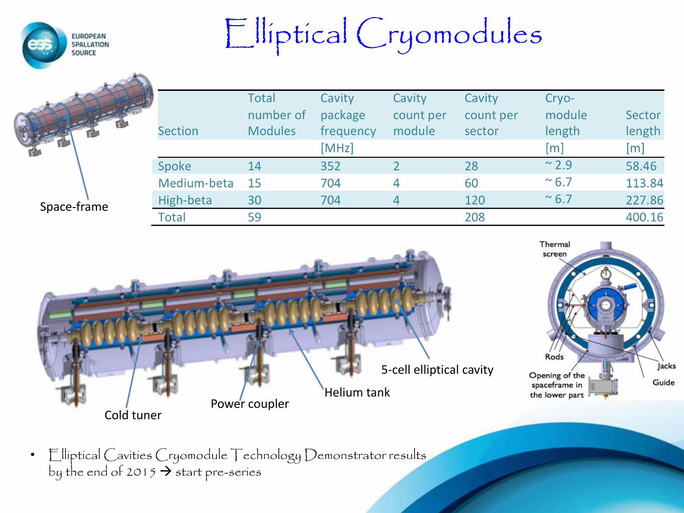
Elliptical Cryomodules
• Elliptical Cavities Cryomodule Technology Demonstrator results by the end of 2015 start pre-series
Space-frame
Power coupler Cold tuner
Helium tank
5-cell elliptical cavity
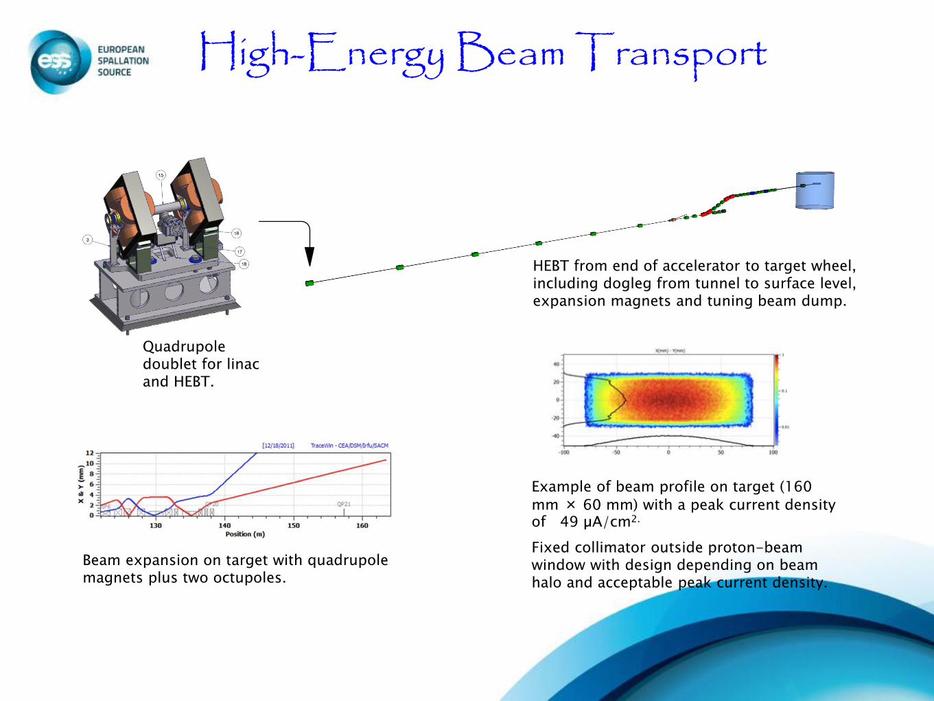
High-Energy Beam Transport
Quadrupole doublet for linac and HEBT.
Beam expansion on target with quadrupole magnets plus two octupoles.
Example of beam profile on target (160
mm × 60 mm) with a peak current density of 49 µA/cm2.
Fixed collimator outside proton-beam window with design depending on beam halo and acceptable peak current density.
HEBT from end of accelerator to target wheel, including dogleg from tunnel to surface level, expansion magnets and tuning beam dump.

Beam instrumentation
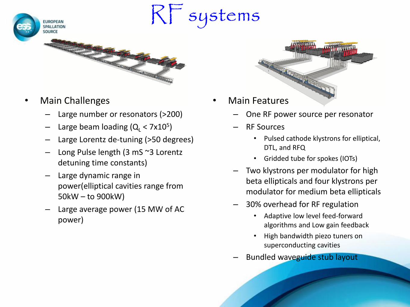
RF systems
• Main Challenges
– Large number or resonators (>200)
– Large beam loading (QL < 7x10⁵)
– Large Lorentz de-tuning (>50 degrees)
– Long Pulse length (3 mS ~3 Lorentz detuning time constants)
– Large dynamic range in power(elliptical cavities range from 50kW – to 900kW)
– Large average power (15 MW of AC power)
• Main Features
– One RF power source per resonator
– RF Sources
• Pulsed cathode klystrons for elliptical, DTL, and RFQ
• Gridded tube for spokes (IOTs)
– Two klystrons per modulator for high beta ellipticals and four klystrons per modulator for medium beta ellipticals
– 30% overhead for RF regulation
• Adaptive low level feed-forward algorithms and Low gain feedback
• High bandwidth piezo tuners on superconducting cavities
– Bundled waveguide stub layout

RF System Procurement Strategy
• Schedule is strongly emphasized
• Procurement Strategy – ESS will write functional technical specifications
• Does *not* impose a topology on the vendors
– Will have at least 2 vendors produce components (modulators, klystrons, circulators for series production)
– Call for tender for production of multiple (3) prototypes • Possibility for multiple vendors to be successful
• At least 1 year soak test on prototypes
– Call for tender for series production based on vendors with successful prototypes

Integrated Control System for ESS
• Decision to have a single integrated control system for ESS – EPICS based – ITER control box concept
• Achievements: – Control Box prototype running at ESS – Naming Convention with tools implemented – Working Development Environment and prototype ESS CODAC – Well defined Safety / Protection system architecture – Parameter List tools developed – Interfaces with the Instrument Controls defined – BLED database for parameters
• Issues: – Target Safety System and Infrastructure Controls requirements immature – Fast data acquisition for Accelerator AND Instruments? – ICS scope not resourced

Reliability, Availability and the ESS
-ESS aim: 95% availability
- higher than any existing facility
- User Centric Availability Definition
Based on discussions with users:
Using weighted % of scheduled beam
power >70% averaged over 1 second.
For example :
Consider a day: one hour of 70%
power, 4 Hrs with 90%, 18.9 Hrs with
100% power and 6 min accelerator trip
gives an availability of: 96.66%
9 Managed by UT-Battelle for the U.S. Department of Energy Presentation_name
High Power Accelerator Reliability
Experience
Similar performance across several facilities
Facilities with the fewest long outages have the highest availability
Data compiled at the 2008 ICFA High Brightness workshop, Nashville TN
ESS
Contribution to down time (>0.4%) E. S. Lessner and P. N. Ostroumov (2005)
Analyses for RIA – 400 KW
SC Linac, availability: 0.96

Uppsala Test Stand • FREIA hall
– ground breaking 14 May 2012
– hall ready by 1 July 2013
• 352 MHz source choice
– report delivered 16 May 2012 (awaiting approval ESS)
– preparing detailed specs for tendering
• cryogenics
– liquefier deadline 20 June 2012
– starting test cryostat design
• installation and commissioning
– preparing detailed planning
14 May 2012
1 July 2013

Test Stand in Lund
Scope:
1. soak tests (1 y) of 3 different prototypes of the 704 MHz modulator;
2. long term (appx 9 m) test of three identical prototypes of the 704 MHz klystron;
3. testing of 704 MHz RF components (circulators, dummy loads);
1. series testing in situ of all 704 MHz modulators
2. series testing in situ of all 704 MHz klystrons
3. series testing of all elliptical cavities cryomodules at full RF load and at final operating temperature
4. vertical test stand for future testing of cavities
- Decision to go ahead with detailed plans for the testing facilities in Lund in summer 2012 to stay on schedule
- Uppsala crucial for 352 MHz development and spokes

LINAC and klystron buildings, principal structure

Possible Design Changes
• Flat power profile (“Galambos margin”) – Could reduce linac length by 400 MeV (6
cryomodules) – Saves money in RF Stations and in cryomodules
• IOT’s – Replace klystrons with IOT’s
• Modulators become much simpler with lower voltage and no switching
• Higher efficiency requires fewer modulators
– Saves: • Saves money as modulator are 30% cheaper • 3-4 MW in RF power (~2-3 Meuro/year)
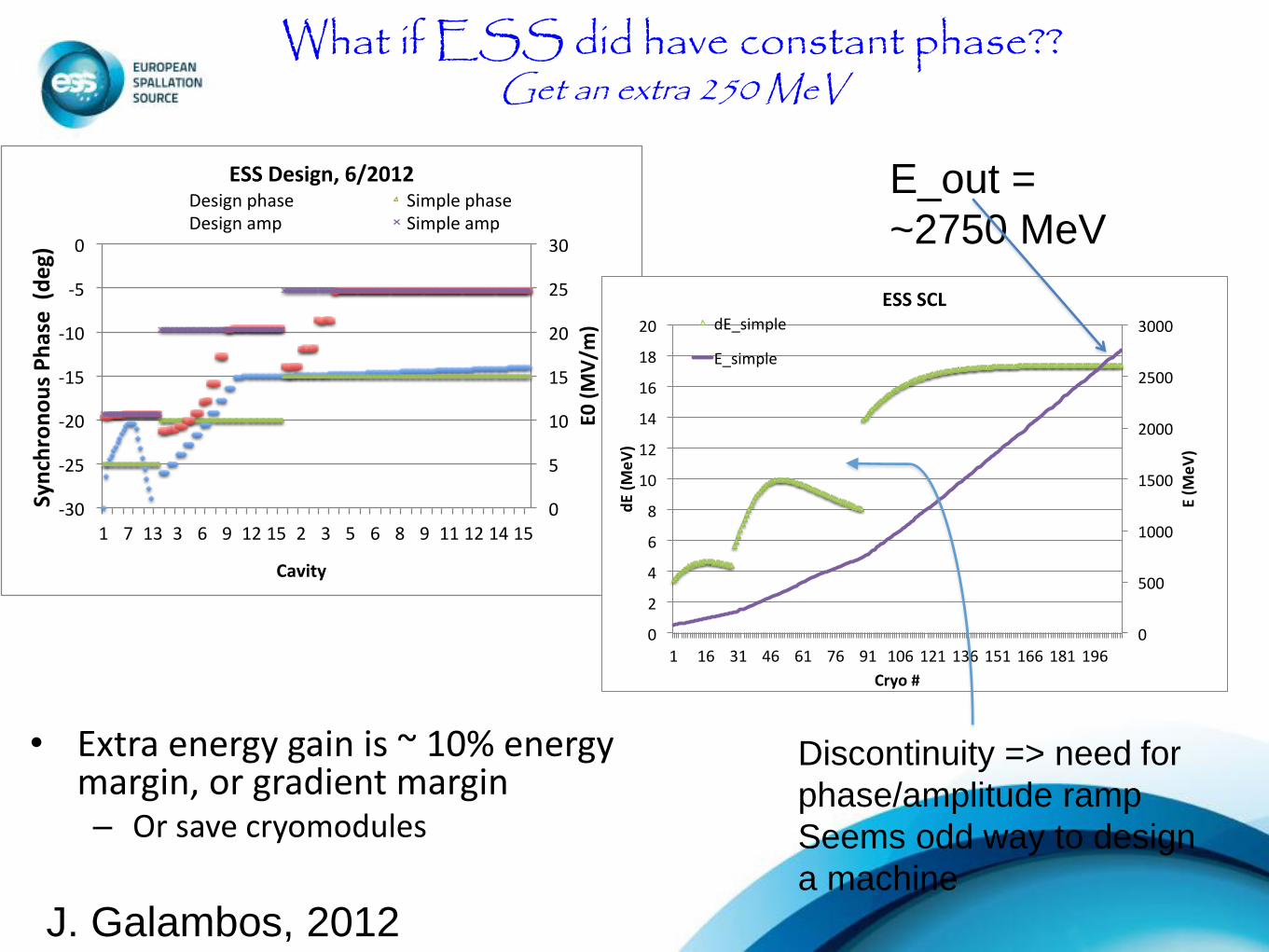
What if ESS did have constant phase?? Get an extra 250 MeV
• Extra energy gain is ~ 10% energy margin, or gradient margin – Or save cryomodules
0
5
10
15
20
25
30
-30
-25
-20
-15
-10
-5
0
1 7133 6 912152 3 5 6 8 911121415
E0(MV/m
)
SynchronousPhase(deg)
Cavity
ESSDesign,6/2012Designphase SimplephaseDesignamp Simpleamp
0
500
1000
1500
2000
2500
3000
0
2
4
6
8
10
12
14
16
18
20
1 16 31 46 61 76 91106121136151166181196
E(M
eV)
dE(M
eV)
Cryo#
ESSSCLdE_simple
E_simple
E_out =
~2750 MeV
Discontinuity => need for
phase/amplitude ramp
Seems odd way to design
a machine
J. Galambos, 2012
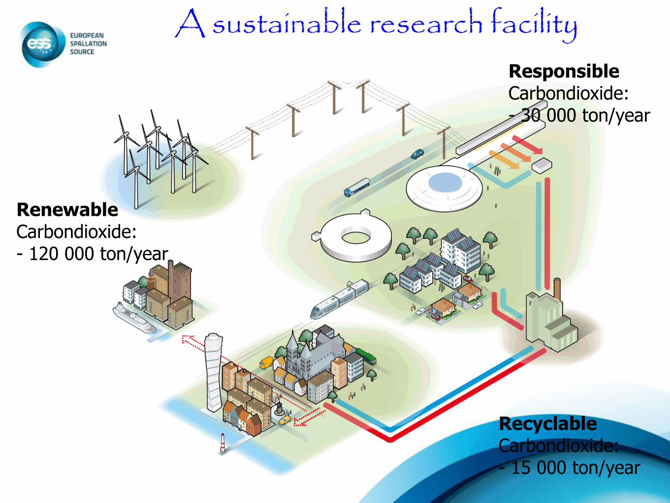
A sustainable research facility
Renewable Carbondioxide: - 120 000 ton/year
Recyclable Carbondioxide: - 15 000 ton/year
Responsible Carbondioxide: - 30 000 ton/year

Challenges • Energy efficiency and recovery is a design goal for a
multi MW facility
– Heat recovery is good but even better are: efficient RF sources, high Q0 cavities, …
• SNS experience indicates that multi MW SC linacs are very flexible and “permitting”
– Can we do joint work on understanding this so that we can do better design work?
• Critical path is RF systems followed by CMs
– Staged installation of ESS with 1.5 MW capability in 2019 and 5 MW capability in 2025
29

Contributors
• Many, many, many thanks to the ESS Accelerator Division, the ADU collaboration and ESS AB
• Slides contributed by: – Håkan Danared, John Galambos, Christine Darve, David
McGinnis, Suzanne Gysin, Juliette Plouin, Guillaume Devanz, Sebastien Bousson, Santo Gammino, Roger Ruber, Søren Pappe-Møller, Andreas Jansson, Mohammad Eshraqi
30

Frozen accelerator design in Falsterbo 2011 ESS, A wonderfull challenge!