The effect of microstructure on abrasive wear of ... 259 52-61.pdf · The effect of microstructure...
10
Wear 259 (2005) 52–61 The effect of microstructure on abrasive wear of hardfacing alloys M.F. Buchely, J.C. Gutierrez, L.M. Le´ on, A. Toro ∗ Tribology and Surfaces Group, National University of Colombia, Medell´ ın, Colombia Received 2 August 2004; received in revised form 1 March 2005; accepted 3 March 2005 Available online 23 May 2005 Abstract Hardfacing is one of the most useful and economical ways to improve the performance of components submitted to severe wear conditions. A study was made to compare the microstructure and abrasion resistance of hardfacing alloys reinforced with primary chromium carbides, complex carbides or tungsten carbides. The hardfacing alloys were deposited onto ASTM A36 carbon steel plates by a shielded metal arc welding (SMAW) method. Three different commercial hardfacing electrodes were employed to investigate the effect of the microstructure. The abrasion tests were carried out in a dry sand–rubber wheel abrasion machine according to the procedure A of ASTM G65 standard. Microstructure characterization and surface analysis were made using optical and scanning electron microscopy. The results showed that the wear resistance is determined by the size, shape, distribution and chemical composition of the carbides, as well as by the matrix microstructure. The best abrasion resistance was obtained in microstructures composed of eutectic matrix and primary M 7 C 3 or MC carbides, while the higher mass losses were measured in completely eutectic deposits. The main wear mechanisms observed at the surfaces included micro-cutting of the matrix and brittle fracture of the carbides. © 2005 Published by Elsevier B.V. Keywords: Hardfacing alloys; Abrasion resistance; Microstructure characterization; Wear mechanisms 1. Introduction Hardfacing is a commonly employed method to improve surface properties of agricultural tools, components for min- ing operation, soil preparation equipments and others [1,2]. An alloy is homogeneously deposited onto the surface of a soft material (usually low or medium carbon steels) by weld- ing, with the purpose of increasing hardness and wear resis- tance without significant loss in ductility and toughness of the substrate. A wide variety of hardfacing alloys is commercially avail- able for protection against wear. Deposits with a microstruc- ture composed by disperse carbides in austenite matrix are extensively used for abrasion applications [3] and are typi- cally classified according to the expected hardness. Never- theless, the abrasion resistance of a hardfacing alloy depends ∗ Corresponding author. Tel.: +57 4 4255254; fax: +57 4 2341002. E-mail address: [email protected] (A. Toro). on many other factors such as the type, shape and distribu- tion of hard phases, as well as the toughness and strain hard- ening behavior of the matrix [4]. Chromium-rich electrodes are widely used due to low cost and availability; however, more expensive tungsten or vanadium-rich alloys offer bet- ter performance due to a good combination of hardness and toughness. Complex carbides electrodes are also used; es- pecially when abrasive wear is accompanied by other wear mechanisms [5]. Several welding techniques such as oxyacetylene gas welding (OAW), gas metal arc welding (GMAW), shielded metal arc welding (SMAW) and submerged arc welding (SAW) can be used for hardfacing. The most important dif- ferences among these techniques lie in the welding efficiency, the weld plate dilution and the manufacturing cost of weld- ing consumables [6]. SMAW, for example, is commonly used due to the low cost of electrodes and easier application. The present investigation aims to study three commercial elec- trodes in terms of their chemical composition, microstruc- ture, hardness and abrasive wear resistance. 0043-1648/$ – see front matter © 2005 Published by Elsevier B.V. doi:10.1016/j.wear.2005.03.002
Transcript of The effect of microstructure on abrasive wear of ... 259 52-61.pdf · The effect of microstructure...

Wear 259 (2005) 52–61
The effect of microstructure on abrasive wear of hardfacing alloys
M.F. Buchely, J.C. Gutierrez, L.M. Leon, A. Toro∗
Tribology and Surfaces Group, National University of Colombia, Medell´ın, Colombia
Received 2 August 2004; received in revised form 1 March 2005; accepted 3 March 2005Available online 23 May 2005
Abstract
Hardfacing is one of the most useful and economical ways to improve the performance of components submitted to severe wear conditions.A study was made to compare the microstructure and abrasion resistance of hardfacing alloys reinforced with primary chromium carbides,complex carbides or tungsten carbides. The hardfacing alloys were deposited onto ASTM A36 carbon steel plates by a shielded metal arcwelding (SMAW) method. Three different commercial hardfacing electrodes were employed to investigate the effect of the microstructure.The abrasion tests were carried out in a dry sand–rubber wheel abrasion machine according to the procedure A of ASTM G65 standard.Microstructure characterization and surface analysis were made using optical and scanning electron microscopy. The results showed that thew rostructure.T erm cro-cutting oft©
K
1
siAsitt
atect
tribu-hard-sver,bet-s andd; es-wear
gasedingdif-
ency,eld-ed. Theelec-ruc-
0d
ear resistance is determined by the size, shape, distribution and chemical composition of the carbides, as well as by the matrix miche best abrasion resistance was obtained in microstructures composed of eutectic matrix and primary M7C3 or MC carbides, while the highass losses were measured in completely eutectic deposits. The main wear mechanisms observed at the surfaces included mi
he matrix and brittle fracture of the carbides.2005 Published by Elsevier B.V.
eywords: Hardfacing alloys; Abrasion resistance; Microstructure characterization; Wear mechanisms
. Introduction
Hardfacing is a commonly employed method to improveurface properties of agricultural tools, components for min-ng operation, soil preparation equipments and others[1,2].n alloy is homogeneously deposited onto the surface of aoft material (usually low or medium carbon steels) by weld-ng, with the purpose of increasing hardness and wear resis-ance without significant loss in ductility and toughness ofhe substrate.
A wide variety of hardfacing alloys is commercially avail-ble for protection against wear. Deposits with a microstruc-
ure composed by disperse carbides in austenite matrix arextensively used for abrasion applications[3] and are typi-ally classified according to the expected hardness. Never-heless, the abrasion resistance of a hardfacing alloy depends
∗ Corresponding author. Tel.: +57 4 4255254; fax: +57 4 2341002.E-mail address:[email protected] (A. Toro).
on many other factors such as the type, shape and distion of hard phases, as well as the toughness and strainening behavior of the matrix[4]. Chromium-rich electrodeare widely used due to low cost and availability; howemore expensive tungsten or vanadium-rich alloys offerter performance due to a good combination of hardnestoughness. Complex carbides electrodes are also usepecially when abrasive wear is accompanied by othermechanisms[5].
Several welding techniques such as oxyacetylenewelding (OAW), gas metal arc welding (GMAW), shieldmetal arc welding (SMAW) and submerged arc weld(SAW) can be used for hardfacing. The most importantferences among these techniques lie in the welding efficithe weld plate dilution and the manufacturing cost of wing consumables[6]. SMAW, for example, is commonly usdue to the low cost of electrodes and easier applicationpresent investigation aims to study three commercialtrodes in terms of their chemical composition, microstture, hardness and abrasive wear resistance.
043-1648/$ – see front matter © 2005 Published by Elsevier B.V.oi:10.1016/j.wear.2005.03.002
M.F. Buchely et al. / Wear 259 (2005) 52–61 53
Table 1Nominal chemical composition of ASTM A36 steel plates (wt%)
C Si S Cu P Fe
0.25 0.40 0.05 0.20 0.04 Balance
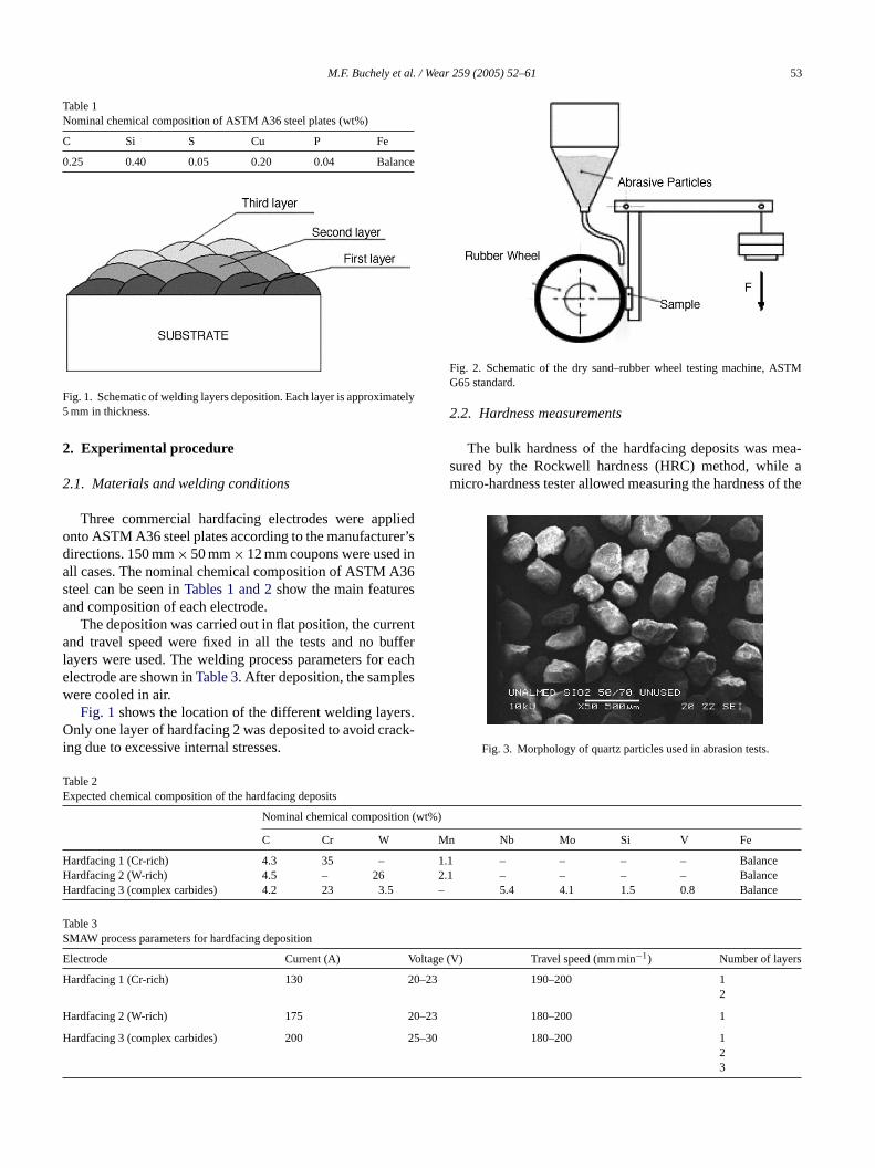
Fig. 1. Schematic of welding layers deposition. Each layer is approximately5 mm in thickness.
2. Experimental procedure
2.1. Materials and welding conditions
Three commercial hardfacing electrodes were appliedonto ASTM A36 steel plates according to the manufacturer’sdirections. 150 mm× 50 mm× 12 mm coupons were used inall cases. The nominal chemical composition of ASTM A36steel can be seen inTables 1 and 2show the main featuresand composition of each electrode.
The deposition was carried out in flat position, the currentand travel speed were fixed in all the tests and no bufferlayers were used. The welding process parameters for eachelectrode are shown inTable 3. After deposition, the sampleswere cooled in air.
Fig. 1shows the location of the different welding layers.Only one layer of hardfacing 2 was deposited to avoid crack-ing due to excessive internal stresses.
Fig. 2. Schematic of the dry sand–rubber wheel testing machine, ASTMG65 standard.
2.2. Hardness measurements
The bulk hardness of the hardfacing deposits was mea-sured by the Rockwell hardness (HRC) method, while amicro-hardness tester allowed measuring the hardness of the
Fig. 3. Morphology of quartz particles used in abrasion tests.
Table 2Expected chemical composition of the hardfacing deposits
Nominal chemical composition (wt%)
C Cr W Mn Nb Mo Si V Fe
Hardfacing 1 (Cr-rich) 4.3 35 – 1Hardfacing 2 (W-rich) 4.5 – 26 2Hardfacing 3 (complex carbides) 4.2 23 3.5 –
TS
E Voltage (V) Travel speed (mm min−1) Number of layers
H 20–23 190–200 12
H 20–23 180–200 1
H 25–30 180–200 123
able 3MAW process parameters for hardfacing deposition
lectrode Current (A)
ardfacing 1 (Cr-rich) 130
ardfacing 2 (W-rich) 175
ardfacing 3 (complex carbides) 200
.1 – – – – Balance
.1 – – – – Balance5.4 4.1 1.5 0.8 Balance

54 M.F. Buchely et al. / Wear 259 (2005) 52–61
phases in the microstructure by using a Vickers indenter witha load of 0.3 kgf.
2.3. Microstructure analysis
Optical (OM) and scanning electron microscopes (SEM)were used to analyze the microstructure of the specimens.Secondary electron imaging allowed morphologic descrip-tion of the worn surfaces, while backscattered electron imag-
Table 4Abrasive wear test conditions, dry sand–rubber wheel testing machine
Procedure Load (N) Velocity (rpm) Wear distance (m)
A 130 200 4309
ing and EDS compositional maps were used to qualitativelydescribe chemical variations in the microstructure. Cross sec-tions of the weld were polished and etched with Kalling’s(hardfacings 2 and 3) and Nital 2% (hardfacing 1). Different
Fca
ig. 4. Hardfacing microstructures: (a) Cr-rich, first layer; (b) Cr-rich, secoarbides, second layer; (f) complex carbides, third layer. Images (a), (b), (d)cquired using scanning electron microscope (SEM).
nd layer; (c) W-rich, first layer; (d) complex carbides, first layer; (e) complexand (e) were acquired using optical microscope (OM) and images (c) and(f) were

M.F. Buchely et al. / Wear 259 (2005) 52–61 55
Fig. 5. EDS compositional map for Cr-rich hardfacing. Cr-rich carbides are revealed.
types of carbides present in the microstructures were firstidentified on the basis of their morphologies and confirmedby micro-hardness measurements.
2.4. Abrasive wear tests
Abrasive wear tests were carried out in a dry sand–rubberwheel testing machine (Fig. 2) according to ASTM G65 stan-dard. Rounded quartz particles with mean diameter between
212 and 300�m were used (Fig. 3). The normal load andduration of the tests are shown inTable 4for each hardfacingtested.
Before the tests, all the specimens were cleaned in ul-trasonic bath and rinsed with warm air. The abrasive wearresistance was determined from the mass loss results, whichwere measured with 0.01 mg resolution, converted to volumelosses and corrected by considering changes in the diameterof the rubber wheel.
Table 5General results from dry sand–rubber wheel abrasion tests
Hardfacing Cr-rich,1st layer
Cr-rich,2nd layer
W-rich,1st layer
Complex carbides,1st layer
Complex carbides,2nd layer
Complex carbides,3rd layer
Mass loss (mg) 292.38 151.9 177.9 385.4 278.5 147.1Volume lossa (mm3) 37.5 19.5 22.8 49.4 35.7 18.8Abrasive wear resistanceb (mg m−1)−1 14.7 28.4 24.2 11.2 15.5 32.3Abrasive wear resistanceb (mm3 m−1)−1 114.9 221.3 188.9 87.2 120.7 228.5
a Average density estimated: 7.8 g cm−3.b Defined as volume loss/sliding distance.

56 M.F. Buchely et al. / Wear 259 (2005) 52–61
3. Results and discussion
3.1. Microstructure
The typical microstructure of the studied hardfacing al-loys is shown inFig. 4. The first and second layers of Cr-richdeposits have a eutectic matrix with proeutectic M7C3-typechromium carbides (1800 HV micro-hardness), which wereidentified by EDS-SEM due to their large size. In the sec-ond layer, both the volume fraction and the mean size ofchromium carbides are higher than in the first one. The vol-ume fraction of chromium carbides in the second layer, cal-culated by using an empirical relation from literature[7], iscirca 52%.
The microstructure of the W-rich deposit is composedby proeutectic MC-type carbides (2500 HV micro-hardness)surrounded by the eutectic structure containing M6C-type(fishbone-type) carbides (1600 HV micro-hardness) andsome martensite.
The first layer of the complex carbides deposit is mainlyeutectic with finely dispersed (Nb, Mo)-rich hard par-ticles, while the second and third deposit layers havea similar microstructure which includes chromium-richM7C3, Nb-rich MC, Mo-rich M2C and W-rich WC car-bides.
Figs. 5–7show EDS compositional maps of the deposits,in which it is possible to identify the carbide types presentin the microstructure. InFig. 8, localized spectra are taken toidentify M2C (Mo-rich), M7C3 (Cr-rich) and MC (Nb-rich)carbides.
3.2. Abrasive wear resistance and mass removalmechanisms
Table 5 and Fig. 9 present the general mass loss andabrasive wear resistance results from the dry sand–rubberwheel tests. The best abrasion resistance was obtainedin the third layer of the complex carbides deposit, in
Fig. 6. EDS compositional map for W-rich har
dfacing. W6C-type carbides can be observed.
M.F. Buchely et al. / Wear 259 (2005) 52–61 57
which the elevated volume fraction of coarse M7C3 car-bides provided a barrier against indentation, groovingand cutting. This beneficial effect is probably reinforcedby the NbC particles, which prevent the detachment ofM7C3 carbides due to their finely dispersed distributionin the matrix and their mechanical properties as well, asshown by Roda Vazquez et al.[3] and Chen and Chang[8].
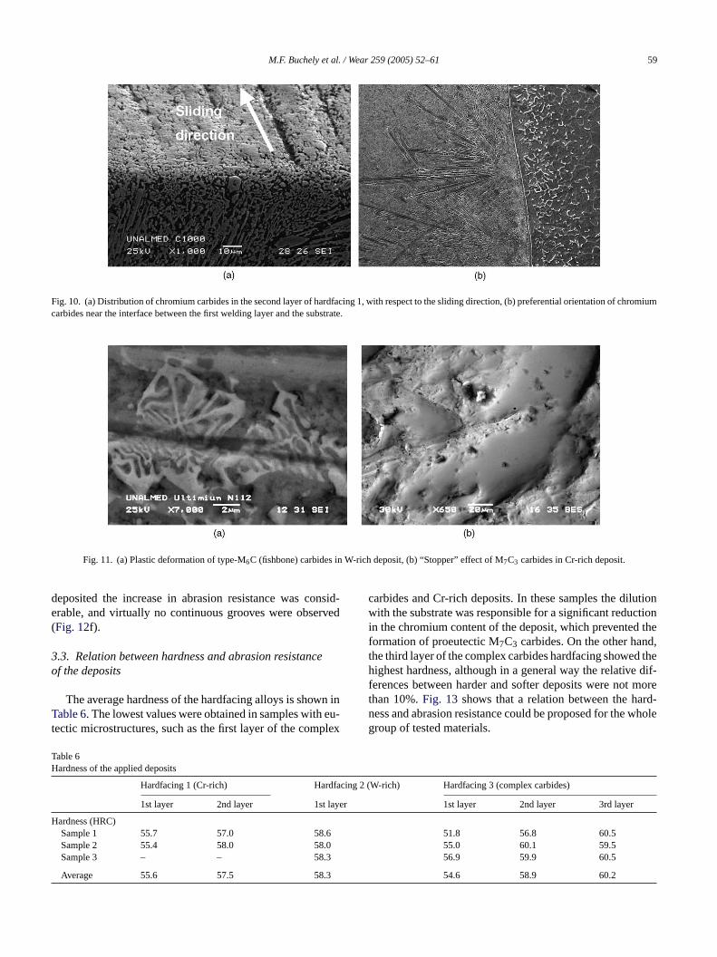
Another important factor in abrasion resistance is car-bide orientation. Carbides in the second layer of Cr-richand third layer of complex carbides hardfacings have no es-pecial orientation (Fig. 10a), while the first layer of bothdeposits showed carbides elongated in direction normalto the interface between the hardfacing and the substrate(Fig. 10b).
As a consequence of their hardness and ability to de-form plastically up to a certain extent, the M6C tungstencarbides (fishbone-type) also contributed to prevent the cut-ting effect of abrasive particles in the W-rich deposit, ascan be seen inFig. 11a. The carbide sinks in the ma-
trix, with no evidence of brittle failure. The “stopper” ac-tion of M7C3 carbides is shown inFig. 11b, in which anabrasive particle was blocked after it was cutting the ma-trix.
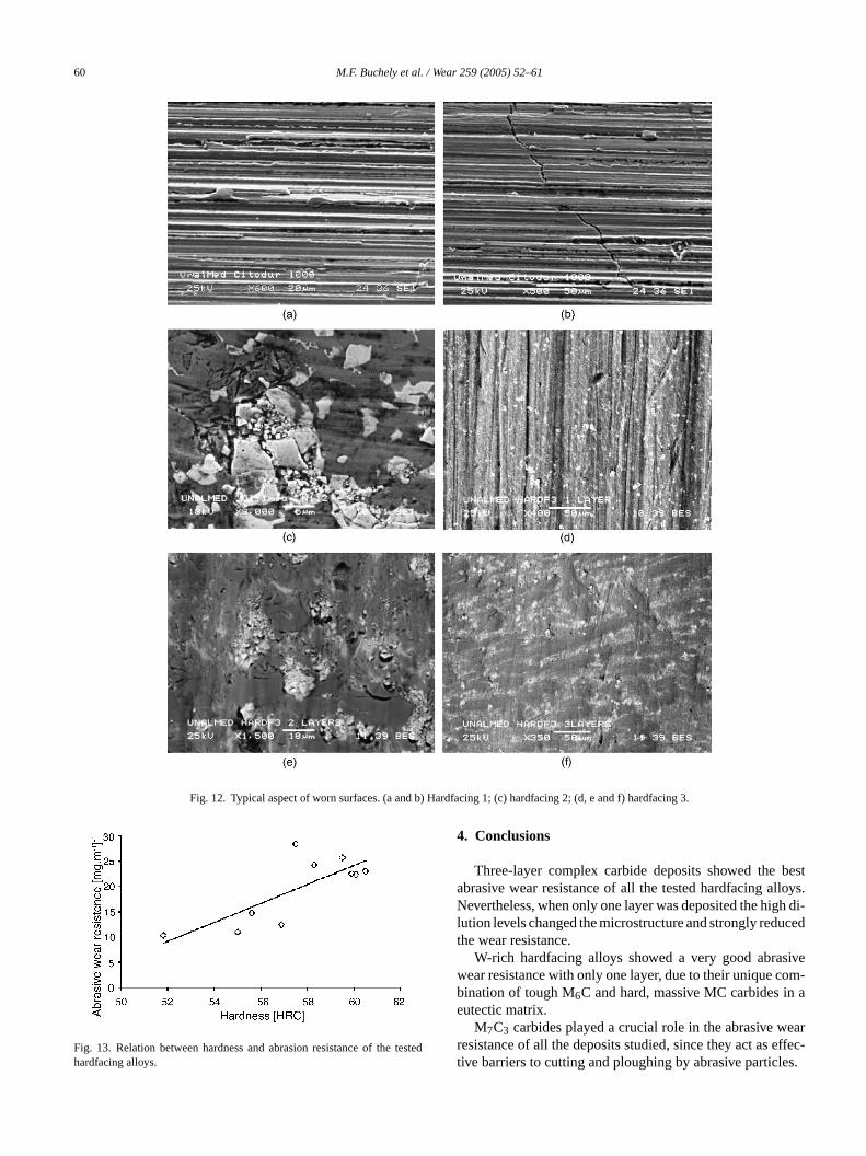
Fig. 12 shows the typical aspect of the worn surfaces.Micro-ploughing and micro-cutting were the main abra-sive micro-mechanisms observed in Cr-rich hardfacing al-loys. In these materials, lips and prows caused by micro-plugging eventually covered previous welding cracks, ascan be seen inFig. 12b. Tungsten carbides in W-rich de-posits had different response as a function of their shapeand size: M6C carbides absorbed high amounts of plas-tic deformation as shown inFig. 11a, while MC carbideswere broken by the abrasive particles (Fig. 12c). In com-plex carbides, hardfacing alloys intense micro-cutting wasobserved when only one layer was applied, due to the ab-sence of massive hard second phases in the microstructure(Fig. 12d). In specimens with two layers brittle fracture ofNbC carbides was observed, together with minor crack for-mation in M7C3 phase (Fig. 12e). When three layers were
Fig. 7. EDS compositional map for complex carbides hard
facing. Carbides rich in different elements can be identified.
58 M.F. Buchely et al. / Wear 259 (2005) 52–61
Fig. 8. EDS spectra showing the different carbides in the microstructure of the complex carbides deposit.
Fig. 9. Abrasive wear resistance of the studied hardfacing alloys.
M.F. Buchely et al. / Wear 259 (2005) 52–61 59
Fig. 10. (a) Distribution of chromium carbides in the second layer of hardfacing 1, with respect to the sliding direction, (b) preferential orientation of chromiumcarbides near the interface between the first welding layer and the substrate.
Fig. 11. (a) Plastic deformation of type-M6C (fishbone) carbides in W-rich deposit, (b) “Stopper” effect of M7C3 carbides in Cr-rich deposit.
deposited the increase in abrasion resistance was consid-erable, and virtually no continuous grooves were observed(Fig. 12f).
3.3. Relation between hardness and abrasion resistanceof the deposits
The average hardness of the hardfacing alloys is shown inTable 6. The lowest values were obtained in samples with eu-tectic microstructures, such as the first layer of the complex
carbides and Cr-rich deposits. In these samples the dilutionwith the substrate was responsible for a significant reductionin the chromium content of the deposit, which prevented theformation of proeutectic M7C3 carbides. On the other hand,the third layer of the complex carbides hardfacing showed thehighest hardness, although in a general way the relative dif-ferences between harder and softer deposits were not morethan 10%.Fig. 13 shows that a relation between the hard-ness and abrasion resistance could be proposed for the wholegroup of tested materials.
Table 6Hardness of the applied deposits
Hardfacing 1 (Cr-rich) Hardfacing 2 (W-rich) Hardfacing 3 (complex carbides)
1st layer 2nd layer 1st layer 1st layer 2nd layer 3rd layer
Hardness (HRC)Sample 1 55.7 57.0 58.6 51.8 56.8 60.5Sample 2 55.4 58.0 58.0 55.0 60.1 59.5Sample 3 – – 58.3 56.9 59.9 60.5
Average 55.6 57.5 58.3 54.6 58.9 60.2
60 M.F. Buchely et al. / Wear 259 (2005) 52–61
Fig. 12. Typical aspect of worn surfaces. (a and b) Hardfacing 1; (c) hardfacing 2; (d, e and f) hardfacing 3.
Fig. 13. Relation between hardness and abrasion resistance of the testedhardfacing alloys.
4. Conclusions
Three-layer complex carbide deposits showed the bestabrasive wear resistance of all the tested hardfacing alloys.Nevertheless, when only one layer was deposited the high di-lution levels changed the microstructure and strongly reducedthe wear resistance.
W-rich hardfacing alloys showed a very good abrasivewear resistance with only one layer, due to their unique com-bination of tough M6C and hard, massive MC carbides in aeutectic matrix.
M7C3 carbides played a crucial role in the abrasive wearresistance of all the deposits studied, since they act as effec-tive barriers to cutting and ploughing by abrasive particles.

M.F. Buchely et al. / Wear 259 (2005) 52–61 61
The main mass removal mechanisms identified after ex-amination of the worn surfaces were micro-cutting, plough-ing and brittle fracture of carbides. Plastic deformation wasalso significant, especially in eutectic microstructures.
Acknowledgement
The authors thank COLCIENCIAS for financial support,contract N. 484-2003.
References
[1] P. Crook, Friction and wear of hardfacing alloys, in: ASM Handbook,Friction, Lubrication and Wear Technology, vol. 18 (1992) 758–765.
[2] I.M. Hutchings, Tribology: Friction and Wear of Engineering Materi-als, Cambridge, 1992, p. 133–171.
[3] C. Roda Vazquez, A. Loureiro, J. Pita Cribeiro, Comportamientofrente al desgaste abrasivo de las aleaciones con tendencia a laformacion de carburos aplicados por soldadura, Mantenimiento 134(2000) 78–89.
[4] S. Chatterjee, T.K. Pal, Wear behavior of hardfacing deposits on castiron, Wear 255 (2003) 417–425.
[5] S.-H. Choo, C.K. Kim, K. Euh, S. Lee, J.-Y. Jung, S. Ahn, Correlationof microstructure with the wear resistance and fracture toughness ofhardfacing alloys reinforced with complex carbides, Metall. Mater.Trans. A 31A (2000) 3041–3052.
[6] W. Wo, L.-T. Wu, The wear behavior between hardfacing materials,Metall. Mater. Trans. A 27A (1996) 3639–3648.
[7] F. Maratray, S. Bechet, Abrasion-Resistant High Chromium WhiteCast Irons, Climax Molybdenum SA Paris Publication, 1971.
[8] H.-X. Chen, Z.C. Chang, Effect of niobium on wear resistance of14% Cr with cast iron, Wear 166 (1993) 197–201.