THE EFFECT OF HOLLOW SECTION TO THE FLEXURAL …
24
PERPUSTAKAAN UMP 11111111111111111111111111111111111111111111111 0000092706 THE EFFECT OF HOLLOW SECTION TO THE FLEXURAL STRENGTH OF THE BEAM MUHAMAD AFIQ BIN AZMAN A report submitted in partial fulfillment of the requirements for the award of the degree of the Bachelor of Civil Engineering Faculty of Civil Engineering & Earth Resources UNIVERSITI MALAYSIA PAHANG JUNE, 2013
Transcript of THE EFFECT OF HOLLOW SECTION TO THE FLEXURAL …

PERPUSTAKAAN UMP
11111111111111111111111111111111111111111111111 0000092706
THE EFFECT OF HOLLOW SECTION TO THE FLEXURAL STRENGTH OF
THE BEAM
MUHAMAD AFIQ BIN AZMAN
A report submitted in partial fulfillment of the requirements
for the award of the degree of the Bachelor of Civil Engineering
Faculty of Civil Engineering & Earth Resources
UNIVERSITI MALAYSIA PAHANG
JUNE, 2013

ABSTRACT
The idea of providing hollow section to the beam in order to reduce the weight of the structure was generally one of the solutions for lightweight beam structure. The concept introduced was the same as hollow slab panels which been widely used in bridge and highway construction. The reduction of the surface area of the beam will give an effect on the bending moment and shear resistance of the beam therefore, an experimental testing was necessary in order to identify the flexural strength, deflection profile and crack pattern of the hollow beam samples. Beam.dimension of (150x200x3000)mm were sampled into Beam 1, Beam 2, Beam 3 and Beam 4. Beam 1 was solid beam with no hollow while Beam 2, Beam 3 and Beam 4 were beam sample with hollow size of (45x45)mm, (70x70)mm and (95x95)mm respectively. For flexural strength, the beam samples were tested under 4-point flexural test and Linear Variable Displacement Transducer (LVDT) were used to measure the deflection of the samples. The crack pattern of beam samples were observed throughout the experiment and the cracking were then analyzed accordingly. The result shows that the flexural strength of the samples reduced to certain degree of percentage of 12.64%, 16.14% and 17.16% for Beam 2, Beam 3 and Beam 4 respectively. Result for deflection shows that Beam 2, Beam 3 and Beam 4 deflected more compared to Beam 1 with percentage increment of 6.27%, 3.19% and 15.74% respectively. As for deflection profile, Beam 1, Beam 2, Beam 3 and Beam 4 show the same profile. Cracking pattern result shows same behavior between all samples while first crack loading result for Beam 1, Beam 2, Beam 3 and Beam 4 was 3lkN, 28kN, 23kN, and 2lkN respectively.
vi
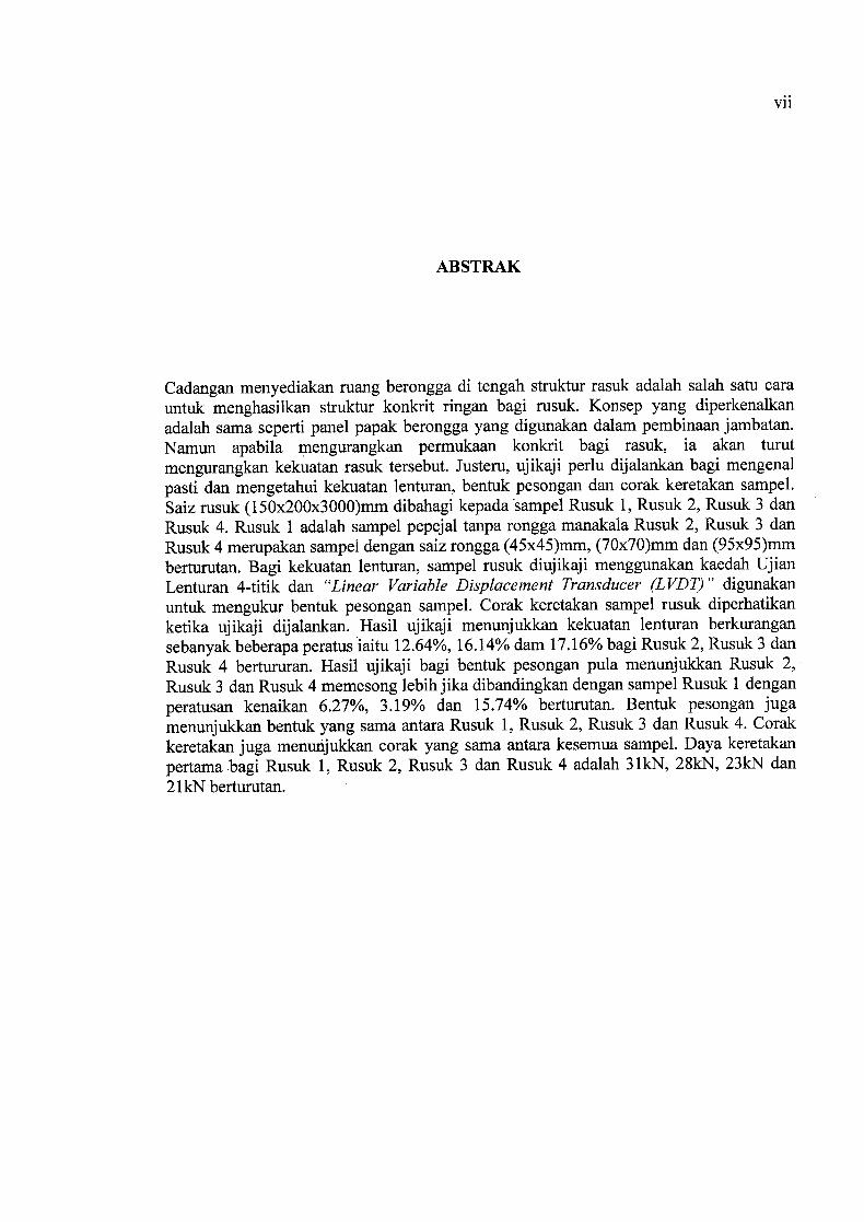
ABSTRAK
Cadangan menyediakan ruang berongga di tengah struktur rasuk adalah salah satu cara untuk menghasilkan struktur konkrit ringan bagi rusuk. Konsep yang diperkenalkan adalah sama seperti panel papak berongga yang digunakan dalam pembinaan jambatan. Namun apabila rnengurangkan permukaan konkrit bagi rasuk, ia akan turut mengurangkan kekuatan rasuk tersebut. Justeru, ujikaji perlu dijalankan bagi mengenal pasti dan mengetahui kekuatan lenturan, bentuk pesongan dan corak keretakan sampel. Saiz rusuk (150x200x3000)mm dibahagi kepada sampel Rusuk 1, Rusuk 2, Rusuk 3 dan Rusuk 4. Rusuk 1 adalah sampel pepejal tanpa rongga manakala Rusuk 2, Rusuk 3 dan Rusuk 4 merupakan sampel dengan saiz rongga (45x45)mm, (7000)mm dan (95x95)mm berturutan. Bagi kekuatan lenturan, sampel rusuk diujikaji menggunakan kaedah Ujian Lenturan 4-titik dan "Linear Variable Displacement Transducer (LVDT)" digunakan untuk mengukur bentuk pesongan sampel. Corak keretakan sampel rusuk diperhatikan ketika ujikaji dijalankan. Hasil ujikaji menunjukkan kekuatan lenturan berkurangan sebanyak beberapa peratus iaitu 12.64%, 16.14% dam 17.16% bagi Rusuk 2, Rusuk 3 dan Rusuk 4 bertururan. Hasil ujikaji bagi bentuk pesongan pula menunjukkan Rusuk 2, Rusuk 3 dan Rusuk 4 memesong lebih jika dibandingkan dengan sampel Rusuk 1 dengan peratusan kenaikan 6.27%, 3.19% dan 15.74% berturutan. Bentuk pesongan juga menunjukkan bentuk yang sama antara Rusuk 1, Rusuk 2, Rusuk 3 dan Rusuk 4. Corak keretakan juga menuiijukkan corak yang sama antara kesemua sampel. Daya keretakan pertama bagi Rusuk 1, Rusuk 2, Rusuk 3 dan Rusuk 4 adalah 3lkN, 28kN, 23kN dan 2lkN berturutan.
vii

TABLE OF CONTENTS
Page
TITLE PAGE
DECLARATION 11
DEDICATION iv
ACKNOWLEDGEMENTS v
ABSTRACT vi
ABSTRAK vii
TABLE OF CONTENTS viii
LIST OF FIGURES xi
LIST OF TABLES xii
CHAPTER 1 INTRODUCTIONS
1.1 Introduction
1.2 Problem statement 2
1.3 Objectives of study 3
1.4 Scope of study 3
viii

CHAPTER 2 LITERATIRE REVIEW
2.1 Introduction 6
2.2 Bending 7
2.3 Deflection 8
2.4 Cracking 9
2.5 Hollow section size 12
CHAPTER 3 METHODOLOGY
3.1 Introduction 13
3.2 Research planning 14
3.3 Sample preparations 15
3.3.1 Formwork preparations 15
3.3.2 Reinforcement preparations 16
3.3.3 Concrete 18
3.3.3.1 Ordinary Portland Cement (OPC) 18
3.3.3.2 Coarse aggregates 20
3.3.3.3 Fine aggregates 21
3.3.3.4 Water 22
3.3.4 Casting process 22
3.3.5 Curing of concrete 23
3.3.5 Painting 24
3.3.7 Testing method 25
3.3.6.1 4-point flexural test 25
IM

CHAPTER 4 RESULT AND DISCUSSION
4.1 Introduction 28
4.2 Flexural strength
29
4.3 Deflection profile 31
4.4 Crack pattern 40
CHAPTER 5 CONCLUSION AND RECOMMENDATIONS
5.1 Introduction 43
43 5.2 Conclusion
5.2 Recommendation 44
REFFERENCES 46
APPENDICES 47

LIST OF FIGURES
Figure No. Title Page
1.1 4-point test 4
3.1 Research experimental work flow 14
3.2 Formwork preparations 16
3.3 Reinforced bar preparations 17
3.4 Coarse aggregate 20
3.5 Fine aggregate 21
3.6 Ready mix concrete 23
3.7 Curing 24
3.8 Painting 27
3.9 Flexural test machine (4-point test) 27
4.1 Loading and flexural strength summary 30
4.2 Force against deflection Beam 1 34
4.3 Force against deflection Beam 2 34
4.4 Force against deflection Beam 3 35
4.5 Force against deflection Beam 4 35
4.6 Deflection profile Beam 1 36
4.7 Deflection profile Beam 2 36
4.8 Deflection profile Beam 3 37
4.9 Deflection profile Beam 4 37
4.10 Crack pattern Beam 1 41
4.11 Crack pattern Beam 2 41
4.12 Crack pattern Beam 3 41
4.13 Crack pattern Beam 4 41
xi

LIST OF TABLES
Table no. Title Page
1.1 Proposed hollow section size 4
1.2 Weight reduction for hollow concrete beam 5
1.3 Mix proportion for concrete mixing 5
3.1 Constituents of OPC 19
4.1 Maximum load and flexural strength of samples 29
4.2 Deflection data summary Beam 1 32
4.3 Deflection data summary Beam 2 32
4.4 Deflection data summary Beam 3 33
4.5 Deflection data summary Beam 4 33
4.6 Deflection profile comparison 39
4.7 Initial crack loading 40
xii

CHAPTER 1
INTRODUCTION
1.1 INTRODUCTION
For this research, the original theory was base from Industrial Building System (IBS) that
introduced by Construction Industry Development Board Malaysia (CIDB) for
construction field in Malaysia. This IBS used widely in other country such as Europe and
United State. Since that, CIDB was taking an approach to introduce the IBS method into
the construction field in Malaysia. IBS method simplified the construction work as a well
as it reduced time consuming also reducing the cost for the construction.
In IBS construction method, precast solid beam is commonly used by the contractor in
order to reduce time consume. Problems occur for the F class contractors which
acknowledging that the precast beam was too heavy to lift without any machinery
support. Therefore, the solution of lightweight beam structure introduced. The idea of
providing hollow section to the beam in order to reduce the weight of the structure was
generally one of the solutions for lightweight beam structure.

2
The concept introduced was the same as hollow slab panels which been widely used in
bridge and highway construction. Referring to the second moment of inertia law, the
reduction of the surface area of the beam will give an effect on the bending moment and
shear resistance of the beam. Therefore, an experimental testing was necessary in order to
identify the reduction of strength of the beam, which resulted from the hollow section
implemented on the beam.
1.2 PROBLEM STATEMENT
A beam is a structural element that is capable of withstanding load primarily by resisting
bending. The bending force induced into the material of the beam as the result of the
external loads, own weight, span and external reactions to these loads is called a bending
moment. Beams are traditionally descriptions of building or civil engineering structural
elements, but smaller structures such as truck or automobile frames, machine frames, and
other mechanical or structural systems contain beam structures that designed and
analyzed in a similar fashion.
The solid beam structure was used widely nowadays and become the major problem as it
carry lot of weight and it lead to difficulty for the contractors to lift and move the
structure to the higher section. Therefore, the hollow section introduced in order to
reduce the weight of the beam. However, since the reduction of the surface area of the
beam will result in the reduction of the strength of the beam itself. Hence, a theoretical
calculation and experimental testing made in order to find the percentage of strength lost
and to provide better recommendation and suggestion for hollow section beam.

3
1.3 OBJECTIVES OF STUDY
The main objectives of this study:
I. To determine the flexural strength of hollow reinforced concrete beam with
different hollow size.
II. To determine the deflection profile of hollow reinforced concrete beam
III. To observe the crack pattern of hollow reinforced concrete beam
1.4 SCOPE OF STUDY
In this experimental study, the effect of hollow section size of the beam on its flexural
strength focused. Four beams with dimension of 200nmTl height, 150mm width and 3
meters span were prepared. Solid beam with no hollow section designed as Beam 1 as a
control parameter and beam with hollow opening 23%, 35% and 48% was designed as
Beam 2, Beam 3 and Beam 4 respectively. The hollow size for Beam 2, Beam 3 and
Beam 4 were (45x45)mm, (70x70)mm, and (95x95)mm respectively. The hollow section
designed to be located at the center of the beam surface area. Table 1.1 shows the
proposed hollow size for the beam and Table 1.2 shows the weight reduction of the beam.
Material such as Ordinary Portland Cements (OPC), sand, coarse aggregates, concrete
reinforced bar and links bar were used. A concrete of grade 30 and uncrushed coarse
aggregate with maximum size of 20mm used. Table 1.3 shows the mix proportion for
lm 3 concrete. As for the reinforcement, reinforcement bar of size 12mm and shear link
bar of size 8mm used. The reinforcement design used for the beam is 2T12 and for shear
link reinforcement of H8-250.The beam samples tested for the flexural strength test to
determine which beam will have the more flexural strength. All beam samples were
compared in term of deflection and crack pattern.

The method chose as an experimental testing was 4-point test (flexural test) and Linear
Variable Displacement Transducer (LVDT) used to observe the deflection of the beam.
Figure 1.1 shows the details of 4-point test that needs to be done, referring to BS 1881-
Part 118-83.
FiR
LVDT 1 LVDT 2 LVDT 3
Figure 1.1: 4-point test
Table 1.1: Proposed hollow section size
% of Hollow Hollow Bar Link Beam
opening Size Area Reinforcement Reinforcement
(mm) (mm 2)
Beam 1 Solid - - 2T12 H8-250
Beam 2 23% 45x45 2025 2T12 H8-250
Beam 3 35% 7000 4900 2T12 H8-250
Beam 4 48% 95x95 9025 2T12 H8-250

Table 1.2: Weight reduction for hollow concrete beams
Beam 1 Beam 2 Beam 3 Beam 4
(Solid) (45x45) (7000) (90x90)
Weight (kg) 225 210 188 157
Weight
Reduction - 15 37 68
(kg)
Table 1.3: Mix proportion for concrete mixing
Quantities Water Cement Fine aggregate Coarse aggregate
(kg) (kg) (kg) (kg)
per 1m3 180' 360 445 1335
per 0.184m3 33.12 66.24 81.88 254.64
Ratio 1 2 2.5 7.5

CHAPTER 2
LITERATURE REVIEW
2.1 INTRODUCTION
Research and study in comparing the strength between solid beam and hollow beam with
the same cross-section and reinforcement had been made before. Some research found
that hollow beam couldn't resist an extra loadings compared to solid beam which can
resist and carry extra load. Therefore this chapter review on the characteristic strength of
hollow beam and how much the strength is reduced dependent on the size of the hollow
sections. The strength of the beam was known to reduce depending on the hollow size on
the beam and this chapter will review the explanations on the hollow beam behaviour and
from those the suggestion and recommendation to increase the concrete hollow beam
strength was observed.
Although the literature covers a wide variety of such theories, this review is focusing on
five major themes which emerge repeatedly throughout the literature reviewed. This
review focused on cracking, deflection and bending. Although the literature presents
these themes in variety of contexts, this review is primarily focus on the explanation in
reduction of hollow beam strength toward bending, crack, deflection and shear.

7
2.2 BENDING
The bending of the structure is depending on the load that acting on the structure such
beam. Solid rectangle beam can resist the bending when the beam is design with applying
the bar and link based on the load acted on the beam. For hollow beam, "The hollow
beam will failed near the design loads while the solid beam will failed more than the
design loads", Alnuaimi et,al. (2007). This statement was supported by Fouad et.al .
(2000) which found that hollow and solid beam with the same reinforcement is having
different strength in term of flexural. This shows that hollow beam bend with small load
acted compared to ' solid beams that can withstand from bending with higher load applied.
According to Alnuaimi et al. (2007) again, beam resisted more load so the maximum
displacement measured was higher in the solid -beam than the hollow beam. With this
review, the hollow beam proved to have lower strength than the solid beam.
On the other hands, according to Yang et al. (2006), mentioned that the beam with
opening is influencing the concrete compressive strength on the capacity of the load
carrying by decreasing the strength significantly with the deep and size of the opening.
The load carrying related to the flexural of the concrete. When the load carrying capacity
is lower, then the beam deflected more. This review have the significant with the research
done by Shanmugam & Swaddiwudhipog (1988), which mentioned that the opening
located at the tension zone affected more on the strength and behavior of the beams
compare to opening that located at the compression zone. The strength of the beam was
mostly related with the bending and flexural of the beam. The less strength of the beam
meant that the beam is bending more. The strength of the beam came from the concrete
and reinforcement bar of the concrete. Additionally, from the research done by Barney et
al. (1977), stated that the opening segment is producing the shear force affecting the
flexural strength simultaneously with the deflection of the beam.

8
2.3 DEFLECTION
The opening or hollow in the structure such as beam required in nowadays building
design for the satisfaction of requirements of placing of ventilation, heat, water and
electricity pipe Nie et al. (2005). However, the hollow beam deflected more than the solid
beam. Therefore, the behavior of the deflection of the hollow beam or an opening beam
required to investigate. Benitez et al. (1998) made a research about the deflection of the
composite beam with web opening. They also describe and come out with the procedures
to calculate the deflection of the beam. However, the equation from Benitez et al. (1998)
not included in this literature due to incapability and too conservative. According to Nie
et.al . (2005), to produce the equation to calculate the deflection of the opening beam, two
assumption were applied which is the maximum, deflection is located at the mid-span of
the beam and the effect of the hollow or opening of the beam were neglected. The
equation is not in use for this study since the opening was transverse of the beam while
the opening for this study was on longitudinal opening. The assumption can be use in
determining the deflection of the hollow beam in this study.
On the others hand, according to Ding et al. (2010), in order to investigate the crack
width opening and the deflection behavior, The crack inside the core or hollow of the
beam was measured simultaneously with the deflection of the beam. Therefore, three
types of graph need to construct in order to get the data, which graph of deflections
against crack, load against deflection and load against crack. According to Benitez et.al
(1998) again mentioned that when there have an opening of the beam, the strain
compatibility is reduced and there are loss of material to carrying the shear that is
effecting on the vertical deflection between the ends of the hollow which was subjected
to the shear. This review shows that the hollow of the beam is affecting the deflection
profile of the beam.

For the other context, according to Campione & Minafo (2012), they did the research
about strength the opening beam by using the vertical strut. Based on the result, they
found that the hollow beam with vertical strut has deflected 15 % greater than the solid
beam. While the other hollow beam without the strut was 20 % to 22%. The present of
the strut is less effective, which only increase about 5% of the deflection. However, the
present of the strut still can help increasing the deflection profile of the beam.
Furthermore, based on research done by Maaddawy & Sherif (2009) stated that the
deflection of the beam is depending on the size of the opening. The larger the size of the
opening inside the concrete beam, the more the beam deflected.
2.4 CRACKING
According to Al Nuaimi et. al. (2007), hollow beams cracked at lower loads than the
solid beams and there were larger number of cracks in hollow beam than the solid
because the core of the concrete for hollow beam reduce the load on the reinforcement
bar which is leads to the higher cracking load. This proved that the solid beam is stronger
than the hollow beam in term of cracking because solid beam can withstand the higher
load before crack than the hollow beam. Similarly, Mitchell & Collins (1979) mentioned
that the solid beam cracked at a higher load than the hollow, which also one of the factors
that can leads to cracking. Mitchell et al. (1979) also mentions and explains that the
earlier cracking of the hollow sections may be due to stress concentrations at the sharp
corners.

10
Furthermore, from the experiment that been conducted by Al Nuaimi & Bhatt (2005),
they have found that all the tested hollow beam was failed in ductile manner where the
steel yielded or reached near yield before the concrete crushed. Both hollow beam and
solid beam failed in a ductile manner with steel yield before crushed. However, from the
studied conducted by Alnuaimi et al. (2007), the beam with high flexural and
displacement leads to failure before crushing. In this context, the hollow beam have high
flexural and displacement than the solid beam. In other context, Wegian & Almottiri
(2007) state that the hollow beam specimen cracked near mid-span and started from
bottom to top. These cracks indicate clearly that the lightly reinforced beam specimens
failed due to pure flexure. This proves that the hollow beam cannot withstand with the
high load and may produce crack and finally failed.
Particularly, there also have some of the researchers do the study on crack pattern.
According to Alnuaimi et al. (2007), beam that subjected to the small load by flexural
test crack almost vertical crack pattern. By the adding of more loads, the crack pattern is
changing the angle from vertical to 45° to 60°. This show that the more the load, the
crack pattern become more inclined. This crack pattern called vertical bending crack and
inclined torsional crack. On the other hand, from the research conducted by Yang & Chen
(2005) mentioned that there have two type of crack pattern which is smeared crack and
discrete crack which able provided satisfactorily the load displacement responses and the
crack path or pattern. Smeared crack modes and discrete crack modes is process where
the works of meshing the crack pattern is carrying on when the crack start to propagated.
This type of crack pattern is when the crack started to appear at mid-span and propagate
upward with increasing crack width. As the load is increasing, the crack is propagate half
of the beam and gradually curved towards the loading point.

11
Besides, Toussaint et al. (2004) in their research mentioned that the crack pattern can
indicates the degradation of stifthess and the plastic part of the stress/strain responses.
Besides, from their research also described the method of checking the crack pattern. The
loading value was taken immediately as soon as the crack started to develop and
propagate. Then the cracks numbered in order of the appearances. The crack pattern can
be achieved by constructing the Flu curve according to the loads when the crack is appear
with the width of the crack. Therefore, the crack pattern were determined by drawing
back the appearing crack pattern to the actual dimension graph. From the Flu curve, the
bond strength between reinforcement bar and concrete can be determined.
In addition, the crack propagation that developed on the beam also can determine whether
the crack developed by subjected to bending or shear. According to Behzad & Ebrahimi
(2008), mentioned that when the beam develop crack at the edge, the beam is not in plane
shape anymore after the deformation. This is due to the shear stress near the crack tip,
which also leads to the warping of the plane section. Any crack propagate at the edge of
the beam or at near the rolling support for this study is expected to undergo the crack
which subjected by the shear stress. Besides, from their research also mentioned that any
crack propagated at the mid-span of the beam is may subjected by bending stress.

12
2.5 HOLLOW SECTION SIZE
As stated by M.A Mansur (2006), the openings that are circular, square, or nearly square
in shape may be considered as small openings provided that the depth (or diameter) of the
opening is in a realistic proportion to the beam size, about less than 40% of the overall
beam depth. In such a case, beam action can be assumed to prevail. Therefore, analysis
and design of a beam with small openings may follow the similar course of action as that
of a solid beam. The provision of openings, however, produces discontinuities or
disturbances in the normal flow of stresses, thus leading to stress concentration and early
cracking around the opening region. Similar to any discontinuity, special reinforcement,
enclosing the opening close to its periphery, should therefore provided in sufficient
quantity to control crack widths and prevent possible premature failure of the beam.

CHAPTER 3
METHODOLOGY
3.1 INTRODUCTION
This chapter will explain about the research that conducted and explain the study carried
out. In this chapter, explanation about the materials used, the research planning and the
testing conducted to determine the characteristic of hollow concrete beam included. This
part also will give the clear point of view about the research and clearly shows how the
objective of this research achieved. At the early stage, the data and the literature review
were collected from the previous study. The source of the study such as books, journals,
magazine, research papers, articles, symposium papers and internet. The discussion
between was crucial in order to improve and gain the knowledge and information
regarding the scope of the research. For this study, the materials used are Portland
cement, coarse aggregate, fine aggregate and polystherene used to create hollow section
of the beam. After casting and curing part done, the specimen will be tests by using
flexural test (4-point test).

3.2 RESEARCH PLANNING
Figure 3.1 shows the research experimental flow for this study.
Prepare 4 beams formwork
(150 X 200 X 3000) Reinforcement preparation for 1 Solid beam with no hollow > the controlled solid beam and
3 Hollow beams with opening hollow section beam
(45x45, 70x70, 95x95) mm
Material preparation
- Ordinary Portland Cement
- Crushed Aggregates Casting the mixture
- Fine Aggregates
- Water
Testing Curing for 28 days
(4 point flexural test)
14
Analysis and Discussions
Figure 3.1: Research experimental works flow

15
3.3 SAMPLE PREPARATIONS
Sample preparation included the preparation of formwork, reinforcement bar, concrete
mixing, casting and curing of sample. This was prepared stage by stage, started with
preparations of formwork and last stage was curing the sample.
3.3.1 Formwork preparations
Formwork is the term given to either temporary or permanent molds which concrete or
similar materials poured. In the context of concrete construction, the formwork supports
the shuttering molds
Early stage of sample preparations was to prepare the formwork for 4 beams sample and
for this research, timber formwork were used. The formwork was prepared using the
same materials and dimension of 150mm x 200mm x 3000mm. The preparation of
formwork is one of the crucial part as the defect occur in this part will affect the beam
sample. The problem that might occur is uneven size of the beam also concrete
segregations.
For formwork preparations, main materials been used was plywood with 1.25cm of
thickness and wood with dimensions of 2.5cm x Scm. Figure 3.2 shows the formwork
sample for the hollow concrete beam. This formwork made up of 3 different part which is
the base, the walls and the faces of the beam. The base was the strongest part of the
formwork and it supported the overall weight of the concrete and the reinforcement. For
wall, it was build both side left and right, and its purpose was to shape and hold the
concrete beam into desirable size and dimensions. Formworks face was the last part
which purpose to seal the formwork and it is located at the front and end of the
formworks.

16
Figure 3.2: Formwork preparations
3.3.2 Reinforcement preparations
A rebar (short for reinforcing bar), also known as reinforcing steel and is commonly used
as a tensioning device in reinforced concrete and reinforced masonry structures holding
the concrete in compression. It is usually in the form of carbon steel bars or wires, and
the surfaces deformed for a better bond with the concrete.
Steel reinforcement preparations divided into two parts which reinforcement bar
preparations and shear link preparations. The reinforcement of the sample provided using
concrete reinforcement design method. Code of study Eurocode used for this design and
this beam considered for residential usage. From the design calculations, reinforcement
bar of 2112 and shear link of H8-300 provided to the beam sample. Shear link was
shaped into rectangular shape with size of 1 5OmmXl 00mm considering the cover of
25mm both from side, bottom and top. The link and reinforcement bar was tie to a length
of 2900mm by considering the cover of 50mm from each end of the formwork.


![Effect of stacking sequence on the flexural and fracture ...125-128]-06.pdf · 125 Effect of stacking sequence on the flexural and fracture properties of carbon/basalt/epoxy hybrid](https://static.fdocuments.net/doc/165x107/5abb1a8f7f8b9a321b8c7363/effect-of-stacking-sequence-on-the-flexural-and-fracture-125-128-06pdf125.jpg)