The Effect of Gravitational Forces on Arabidopsis Thaliana ...
23
0 NASA Student Launch Initiative 2006 The Effect of Gravitational Forces on Arabidopsis Thaliana Development Critical Design Review Madison West High School 30 Ash Street Madison, WI 53726 Ed Holmes, Principal
Transcript of The Effect of Gravitational Forces on Arabidopsis Thaliana ...
0
NASA Student Launch Initiative 2006
The Effect of Gravitational Forces on Arabidopsis Thaliana Development
Critical Design Review
Madison West High School 30 Ash Street
Madison, WI 53726 Ed Holmes, Principal
1
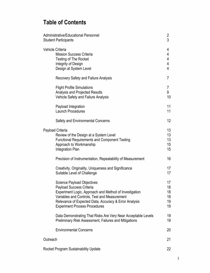
Table of Contents Administrative/Educational Personnel 2 Student Participants 3 Vehicle Criteria 4 Mission Success Criteria 4 Testing of The Rocket 4
Integrity of Design 4 Design at System Level 4 Recovery Safety and Failure Analysis 7 Flight Profile Simulations 7 Analysis and Projected Results 9 Vehicle Safety and Failure Analysis 10 Payload Integration 11 Launch Procedures 11 Safety and Environmental Concerns 12
Payload Criteria 13 Review of the Design at a System Level 13 Functional Requirements and Component Testing 13 Approach to Workmanship 15 Integration Plan 15 Precision of Instrumentation, Repeatability of Measurement 16 Creativity, Originality, Uniqueness and Significance 17 Suitable Level of Challenge 17 Science Payload Objectives 17 Payload Success Criteria 18 Experiment Logic, Approach and Method of Investigation 18 Variables and Controls, Test and Measurement 18 Relevance of Expected Data, Accuracy & Error Analysis 19
Experiment Process Procedures 19 Data Demonstrating That Risks Are Very Near Acceptable Levels 19 Preliminary Risk Assessment, Failures and Mitigations 19 Environmental Concerns 20
Outreach 21 Rocket Program Sustainability Update 22
2
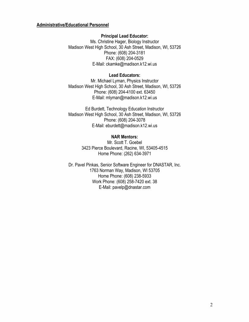
Administrative/Educational Personnel
Principal Lead Educator: Ms. Christine Hager, Biology Instructor
Madison West High School, 30 Ash Street, Madison, WI, 53726 Phone: (608) 204-3181 FAX: (608) 204-0529
E-Mail: [email protected]
Lead Educators: Mr. Michael Lyman, Physics Instructor
Madison West High School, 30 Ash Street, Madison, WI, 53726 Phone: (608) 204-4100 ext. 63450
E-Mail: [email protected]
Ed Burdett, Technology Education Instructor Madison West High School, 30 Ash Street, Madison, WI, 53726
Phone: (608) 204-3078 E-Mail: [email protected]
NAR Mentors:
Mr. Scott T. Goebel 3423 Pierce Boulevard, Racine, WI, 53405-4515
Home Phone: (262) 634-3971
Dr. Pavel Pinkas, Senior Software Engineer for DNASTAR, Inc. 1763 Norman Way, Madison, WI 53705
Home Phone: (608) 238-5933 Work Phone: (608) 258-7420 ext. 38
E-Mail: [email protected]
3
Student Participants
Key Managers (See Appendices A-B) Corey Watts (Grade 12)
[email protected] Proposed Duty: Research and development of payload.
Dean Weesner (Grade 11)
[email protected] Proposed Duty: Research and development of payload.
Key Technical Personnel (See Appendices C-D)
Grant Bilstad (Grade 11) [email protected]
Proposed Duty: Chief vehicle designer.
Adeyinka Lesi (Grade 12) [email protected]
Proposed Duty: Vehicle designer.
Key Support Personnel (See Appendices E-I) Michael Balantekin (Grade 11) [email protected]
Proposed Duty: Safety.
Gabe Lezra (Grade 11) [email protected] Proposed Duty: Research.
Liz Sinclair (Grade 11)
[email protected] Proposed Duty: Chief botanical expert.
Jacinth Sohi (Grade 11) [email protected]
Proposed Duty: Chief media and public relations director.
Rose Weisshaar (Grade 11) [email protected]
Proposed Duty: Research and implementation of payload design.
4
I) Vehicle Criteria TESTING AND DESIGN OF VEHICLE Mission Success Criteria The mission of this project is to successfully launch a vehicle transporting a scientific payload of Arabidopsis Thaliana, to an altitude of 5,280 feet. The rocket will consist of two stages, the first powered by a J-class hybrid motor, the second powered by a J-class solid motor. Both of these stages will be carrying payload of Petri dishes housing Arabidopsis Thaliana specimens. A Rocket Data Acquisition System (RDAS) will also be present in the vehicle, enabling the collection of acceleration values over the course of time. The requirements for the success of this mission include a functioning rocket and its subsystems. The vehicle succeeds under several conditions. Primarily, the first stage of the rocket must launch successfully. Next, the second stage of the rocket must properly ignite and continue flying to an altitude of one mile. Third, both the first and second stages must safely return to the ground intact. Of course, to achieve any of these elements, good workmanship is key. In the construction of the rocket, students must exercise care and use precision to ensure exquisite craftsmanship. If proper workmanship is lacking and the rocket is constructed in a poor manner, less than satisfactory mission success is inevitable. Testing of the Rocket: Initially, the stability of the rocket will be tested using computer-generated pre-visualizations acquired from programs such as RockSim. Scale models of the rocket will then be flown to test the design of the rocket (scale model is already built). To accurately represent the final rocket in these test flights, a faux payload of proportional dimensions and weight will be included to simulate the actual payload. Additionally, several tests of the full scale vehicle are planned. We will begin with the sustainer testing to make sure that the upper stage can endure high values of acceleration (40g+) and then move to 0.25mile and 0.5mile flights of the whole vehicle, including both stages. Finally, if time and resources allow, we plan to conduct a 1 mile, all systems running test flight about 2 weeks before our trip to MSFC. Integrity of Design The rocket was designed using RockSIM CAD software. This software allows for flight simulations that can be used to test the effects of various parameters on the flight of the rocket, such as wind speed and ballast. The half scale model will be built and flown to prove the validity of the design. All planned vehicles were designed by the students experienced with model rocket design (TARC-2005 finalists) and the final rocket designs were checked and reviewed by a Level-2 HPR certified mentor (Mr. Goebel). Design at System Level Required Subsystems:
• First Stage: Propulsion System, Structural System, Payload Bay System, Deployment System, Recovery System, Tracking System
• Second Stage: Propulsion System, Structural System, Payload Bay System, Deployment System, Recovery System, Tracking System
• Other: Launch System, Recovery System
5
First Stage: • Propulsion System: The propulsion system will consist of a J class hybrid motor unit,
fueled by nitrous oxide and polyvinyl chloride. The motors will be firmly mounted in the motor mount tubes. The booster motor mount assembly may prove to be more complex because of the use of a hybrid. Most likely a “C-clip” method of motor retention will be implemented.
• Structural System: The booster portion will consist of 6.0 inch fiberglass tubes ordered form Public Missiles, Ltd. The transition to the second stage for the rocket will be either a foam or balsa core covered with carbon-fiber, fiberglass, Kevlar or combinations. All these components will give us a very sounding and solid airframe. The trapezoid shape used for the fins (in both stages) has been used in prior rockets and proves to be a simple shape to manufacture. The sweep of the fins also gives worthy aerodynamics. Shape and size of the fins are critical in that it will greatly influence the center of pressure of the rocket.
• Payload Bay System: The payload bay system will be a phenolic tube coupler that houses Petri dishes, and will be sealed with epoxy coated plywood caps on both ends. This whole unit is then placed in the rocket.
• Deployment System: The deployment system will consist of two timers for stage separation and parachute deployment. The timers will ignite electronic matches to set off a deployment charge. (The timers will be most likely doubled for the redundancy and each of the timers will have its own power source).
• Tracking System: The tracking system will consist of a 140dB screamer and AM beacon transmitting on 434MHz frequency.
• Recovery System: We will use a single deployment system for the first stage and a dual deployment system for the second stage. The sizes for the parachutes and the drop rates during vehicle recovery will be as follows:
Parachute Size (in) Descent Rate (fps) Weight (lbs) First Stage Main 96 15 11.0 Second Stage Drogue
15 50 5.8
Second Stage Main+Drouge
70 (main) + 15 (drogue) 15 5.8
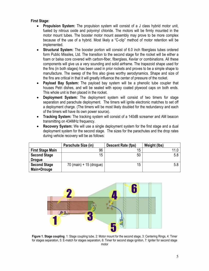
Figure 1. Stage coupling. 1: Stage coupling tube, 2: Motor mount for the second stage, 3: Centering Rings, 4: Timer for stages separation, 5: E-match for stages separation, 6: Timer for second stage ignition, 7: Igniter for second stage
motor
6
Second Stage:
• Propulsion System: The propulsion system will consist of a solid-fuel J class motor (J800T). This will be inserted into the motor mount, which will be centered inside the rocket body by two aircraft plywood rings. The motor mount tubes are phenolic tubing of respective sizes. . Active motor retention using fitted brackets for the sustainer portion of the rocket will hold the motor casing in place.
• Structural System: The structural system will consist of a 4-inch tube covered with Kevlar and three fins made of G10 Fiberglass. The airframe for the Sustainer section of the rocket will be “4.0 inch” Fiberglass tubes ordered from Public Missiles, Ltd.
• Payload Bay System: same as in the first stage • Deployment System: The deployment system for the second stage will be two dual event
altimeters (see Figure 2). They will both fire the same charge at the apogee to deploy drogue parachute and then again they both will fire another charge to deploy the parachute at 500 feet. We are using two altimeters so we have some redundancy (if one fails, the other one still fires the necessary charges).
• Tracking System: The tracking system will consist of an AM radio beacon and two 140dB screamers.
• Recovery System: We will use a single deployment system for the first stage and a dual deployment system for the second stage. For sizes of the parachutes, see the table under the First Stage section, subsection “Recovery System.”
Other: • Launch System: This system consists of the ground support equipment for the Hypertek
Hybrid Motor System and a launch tower.
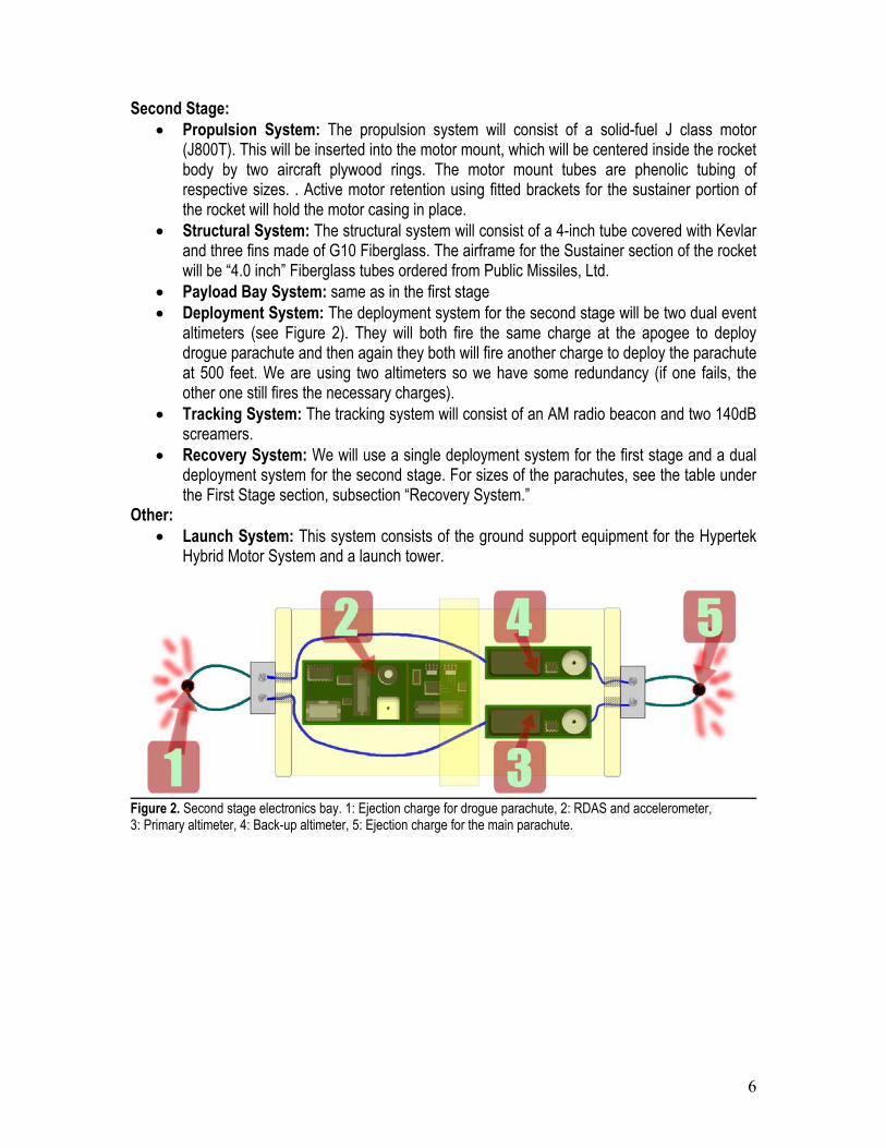
Figure 2. Second stage electronics bay. 1: Ejection charge for drogue parachute, 2: RDAS and accelerometer, 3: Primary altimeter, 4: Back-up altimeter, 5: Ejection charge for the main parachute.
7
RECOVERY For information regarding the parachute, see section “Design at System Level” subsection “Recovery System.” Recovery Safety and Failure Analysis
Problem Result Mitigation Recovery Failure—parachutes
fail to deploy or become tangled
Ballistic fall of rocket and/or payload.
Parachute will be properly prepared and installed before
the launch. Transportation—rocket is
damaged during transportation Possible aberrations in launch,
flight, or recovery Rocket will be properly
packaged for transportation and inspected carefully before
the launch. Rocket is Carried off by Strong
Wind Rocket is lost. Mission failure. A tracking system will be used
to locate the rocket. Radio beacon and screamers provide
help in finding the rocket. Parachute is Tangled Unsafe landing of rocket. Parachute shock cords will be
carefully folded and inserted to prevent entanglement.
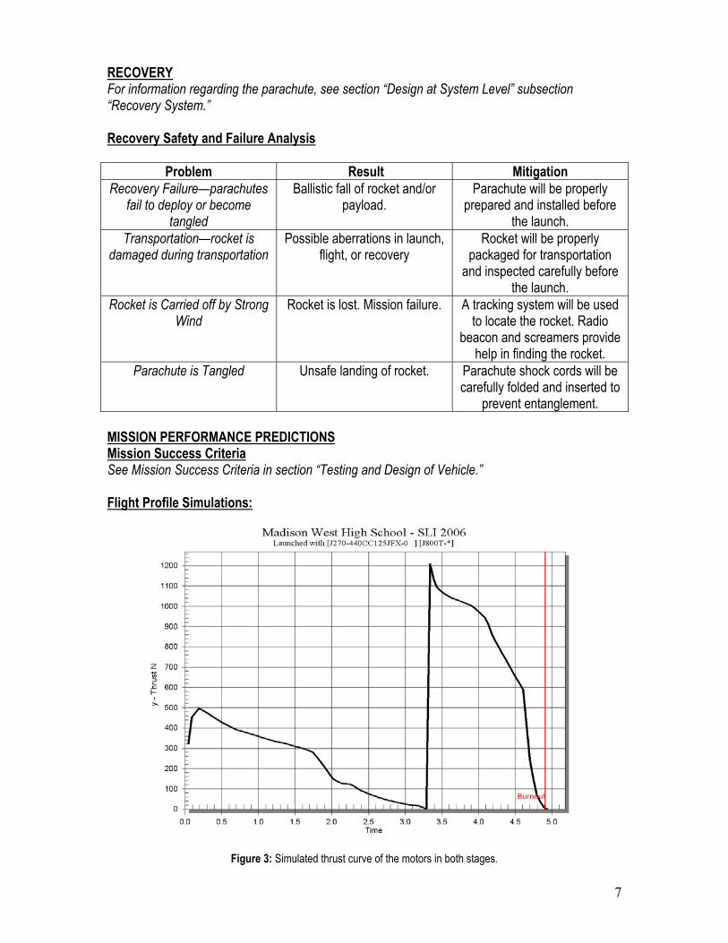
MISSION PERFORMANCE PREDICTIONS Mission Success Criteria See Mission Success Criteria in section “Testing and Design of Vehicle.” Flight Profile Simulations:
Figure 3: Simulated thrust curve of the motors in both stages.
8
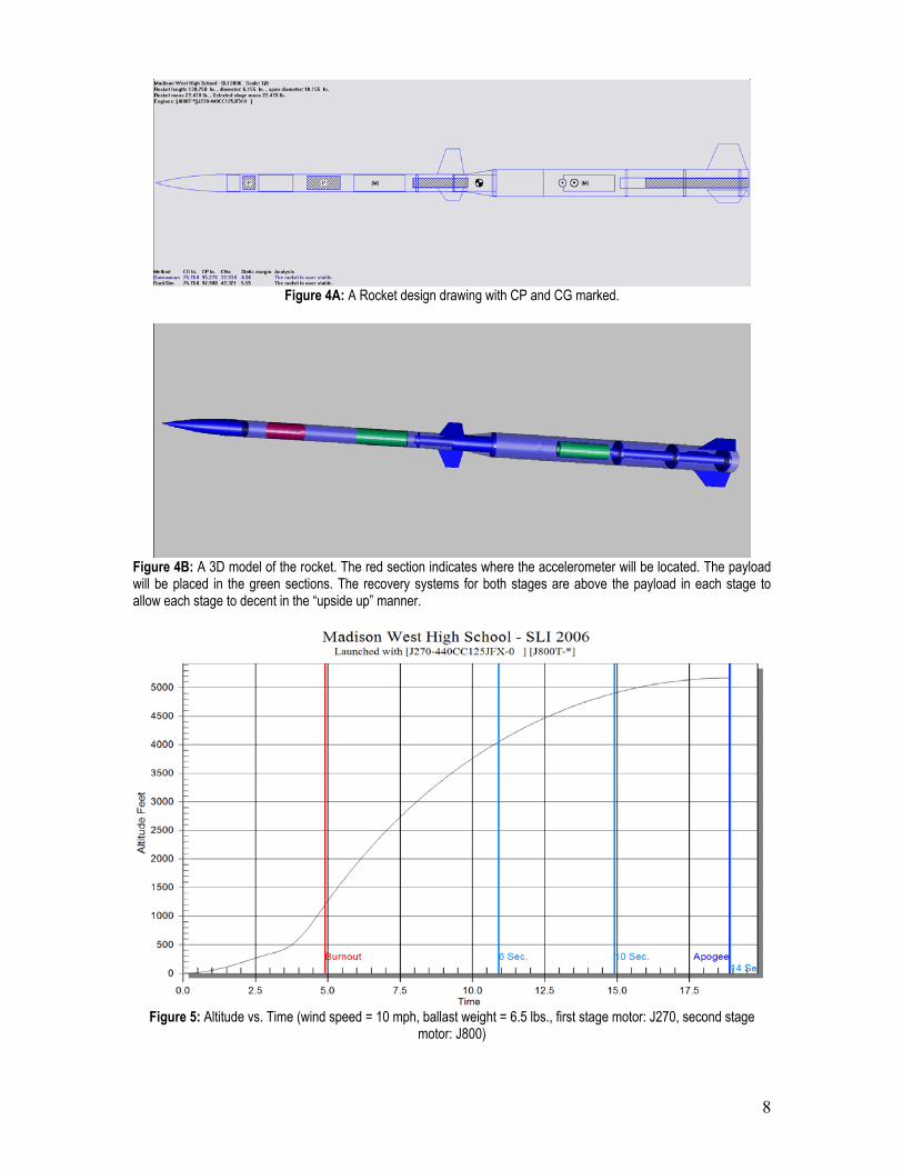
Figure 4A: A Rocket design drawing with CP and CG marked.
Figure 4B: A 3D model of the rocket. The red section indicates where the accelerometer will be located. The payload will be placed in the green sections. The recovery systems for both stages are above the payload in each stage to allow each stage to decent in the “upside up” manner.
Figure 5: Altitude vs. Time (wind speed = 10 mph, ballast weight = 6.5 lbs., first stage motor: J270, second stage
motor: J800)
9
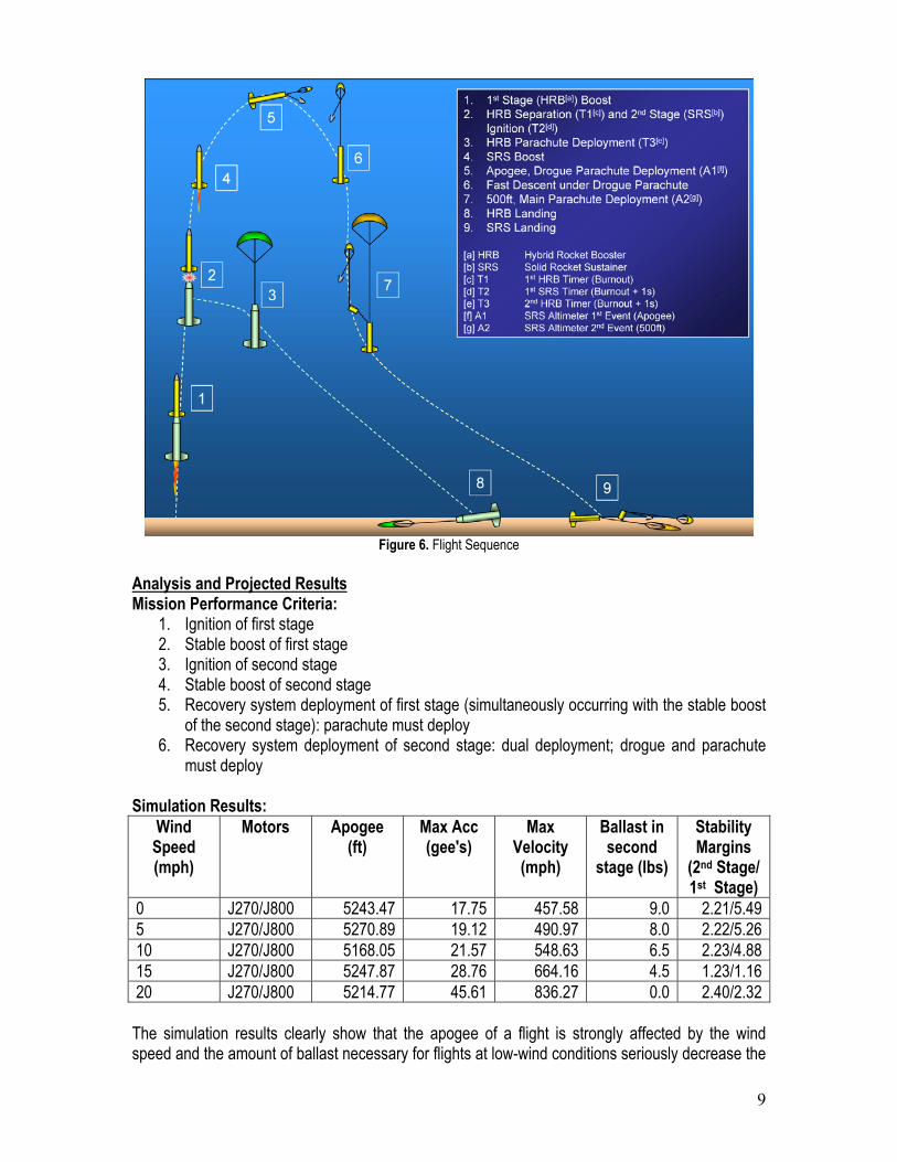
Figure 6. Flight Sequence
Analysis and Projected Results Mission Performance Criteria:
1. Ignition of first stage 2. Stable boost of first stage 3. Ignition of second stage 4. Stable boost of second stage 5. Recovery system deployment of first stage (simultaneously occurring with the stable boost
of the second stage): parachute must deploy 6. Recovery system deployment of second stage: dual deployment; drogue and parachute
must deploy Simulation Results:
Wind Speed (mph)
Motors Apogee (ft)
Max Acc (gee's)
Max Velocity (mph)
Ballast in second
stage (lbs)
Stability Margins
(2nd Stage/ 1st Stage)
0 J270/J800 5243.47 17.75 457.58 9.0 2.21/5.49 5 J270/J800 5270.89 19.12 490.97 8.0 2.22/5.26 10 J270/J800 5168.05 21.57 548.63 6.5 2.23/4.88 15 J270/J800 5247.87 28.76 664.16 4.5 1.23/1.16 20 J270/J800 5214.77 45.61 836.27 0.0 2.40/2.32 The simulation results clearly show that the apogee of a flight is strongly affected by the wind speed and the amount of ballast necessary for flights at low-wind conditions seriously decrease the
10
maximum acceleration achieved by the second stage (the ballast is added to reach exactly 1 mile of altitude). To lessen this undesired effect we plan to add spin stabilization to the vehicle and use a very long rail to allow the rocket to speed up as much as possible before it leaves the ground based guidance system. The half scale model will be constructed and flown to obtain real flight data that will aid us in possible further redesign of the vehicle. Vehicle Safety and Failure Analysis
Problem Result Mitigation Rocket doesn’t stage Second half of experiment is
not carried out. We will do extensive testing of
staging mechanisms during prototype and test flights
Faulty Design—unstable rocket Unsuccessful flight. We are doing computer simulations, low altitude flights, and prototype flights to make sure that the rocket is stable
Faulty Design—structural failure
Rocket disintegrates. Sturdy materials (Kevlar, fiberglass, epoxy, etc.) that can
sustain the stresses of the flight will be used.
First Stage Failure—rocket doesn’t ignite
Nothing happens. We use the igniters and motors properly so they do ignite.
Launch failure—launch rod malfunction
Rocket leaves launch pad at an undesired angle.
Launch rod will be leveled, lubricated, and secured to a
stable surface. Staging Failure—catastrophic
motor malfunction Rocket explodes. (Severe damage to the rocket and
motor casing.)
Motors are properly stored and used.
Transportation—rocket is damaged during transportation
Possible aberrations in launch, flight, or recovery
Rocket will be properly packaged for transportation
and inspected carefully before the launch.
Stage Separation Failure- Second stage does not
separate from first stage
First Stage is severely damaged. The plants are
destroyed due to exposure to heat.
The stages will be attached loosely so that they can
separate easily.
Timers Do Not Initiate Reaction at the Proper Time
Stages do not separate and/or parachutes/ drogue do not
deploy.
Rigorous tests of the timers’ accuracy will be performed
during test flights. RDAS Failure We would have no acceleration
data. Test RDAS during test flights
and prior to launching to ensure that it is functioning
properly before being inserted in the rocket. Insert fresh batteries prior to launch.
11
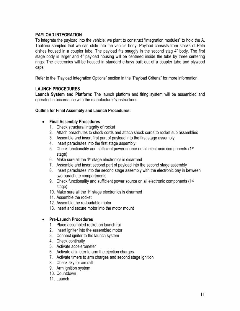
PAYLOAD INTEGRATION To integrate the payload into the vehicle, we plant to construct “integration modules” to hold the A. Thaliana samples that we can slide into the vehicle body. Payload consists from stacks of Petri dishes housed in a coupler tube. The payload fits snuggly in the second stag 4” body. The first stage body is larger and 4” payload housing will be centered inside the tube by three centering rings. The electronics will be housed in standard e-bays built out of a coupler tube and plywood caps. Refer to the “Payload Integration Options” section in the “Payload Criteria” for more information. LAUNCH PROCEDURES Launch System and Platform: The launch platform and firing system will be assembled and operated in accordance with the manufacturer’s instructions. Outline for Final Assembly and Launch Procedures:
• Final Assembly Procedures 1. Check structural integrity of rocket 2. Attach parachutes to shock cords and attach shock cords to rocket sub assemblies 3. Assemble and insert first part of payload into the first stage assembly 4. Insert parachutes into the first stage assembly 5. Check functionality and sufficient power source on all electronic components (1st
stage) 6. Make sure all the 1st stage electronics is disarmed 7. Assemble and insert second part of payload into the second stage assembly 8. Insert parachutes into the second stage assembly with the electronic bay in between
two parachute compartments 9. Check functionality and sufficient power source on all electronic components (1st
stage) 10. Make sure all the 1st stage electronics is disarmed 11. Assemble the rocket 12. Assemble the re-loadable motor 13. Insert and secure motor into the motor mount
• Pre-Launch Procedures 1. Place assembled rocket on launch rail 2. Insert igniter into the assembled motor 3. Connect igniter to the launch system 4. Check continuity 5. Activate accelerometer 6. Activate altimeter to arm the ejection charges 7. Activate timers to arm charges and second stage ignition 8. Check sky for aircraft 9. Arm ignition system 10. Countdown 11. Launch
12
• Disarming Procedure (in case motor doesn’t ignite)
1. Remove ignition interlock to prevent accidental ignition 2. Wait designated time by HPR safety code (1 minute) 3. Disarm electronics and remove rocket from pad 4. Reinstall igniter 5. Place rocket back on pad, re-arm electronics 6. Test continuity
SAFETY For Preliminary Risk Assessment, see risk plots for both Safety Failure Analysis and proposed mitigations. Environmental Concerns Launching rockets has the potential to harm the environment. When parts of the rocket aren’t recovered, it is possible that they can physically harm some animals, or that the materials that the rocket is made of may damage the environment. Fumes emitted from the engine of the rocket during the launch can possibly cause air pollution. To try to minimize the potential environmental hazards associated with rocketry, we will strictly comply with all state and federal environmental regulations. We will make sure that great efforts are taken to recover all parts of the rocket; anything that we put into the environment when we launch, we will take out when we leave.
13
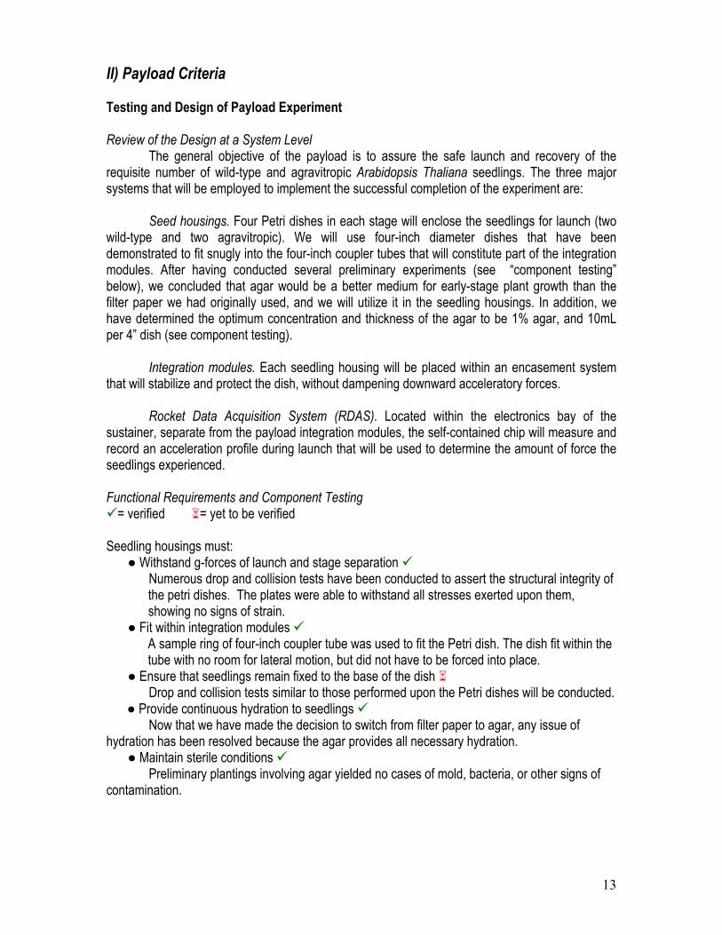
II) Payload Criteria Testing and Design of Payload Experiment Review of the Design at a System Level The general objective of the payload is to assure the safe launch and recovery of the requisite number of wild-type and agravitropic Arabidopsis Thaliana seedlings. The three major systems that will be employed to implement the successful completion of the experiment are: Seed housings. Four Petri dishes in each stage will enclose the seedlings for launch (two wild-type and two agravitropic). We will use four-inch diameter dishes that have been demonstrated to fit snugly into the four-inch coupler tubes that will constitute part of the integration modules. After having conducted several preliminary experiments (see “component testing” below), we concluded that agar would be a better medium for early-stage plant growth than the filter paper we had originally used, and we will utilize it in the seedling housings. In addition, we have determined the optimum concentration and thickness of the agar to be 1% agar, and 10mL per 4” dish (see component testing).
Integration modules. Each seedling housing will be placed within an encasement system that will stabilize and protect the dish, without dampening downward acceleratory forces.
Rocket Data Acquisition System (RDAS). Located within the electronics bay of the
sustainer, separate from the payload integration modules, the self-contained chip will measure and record an acceleration profile during launch that will be used to determine the amount of force the seedlings experienced. Functional Requirements and Component Testing
= verified = yet to be verified Seedling housings must:
● Withstand g-forces of launch and stage separation Numerous drop and collision tests have been conducted to assert the structural integrity of the petri dishes. The plates were able to withstand all stresses exerted upon them, showing no signs of strain.
● Fit within integration modules A sample ring of four-inch coupler tube was used to fit the Petri dish. The dish fit within the tube with no room for lateral motion, but did not have to be forced into place.
● Ensure that seedlings remain fixed to the base of the dish Drop and collision tests similar to those performed upon the Petri dishes will be conducted.
● Provide continuous hydration to seedlings Now that we have made the decision to switch from filter paper to agar, any issue of hydration has been resolved because the agar provides all necessary hydration.
● Maintain sterile conditions Preliminary plantings involving agar yielded no cases of mold, bacteria, or other signs of contamination.
14
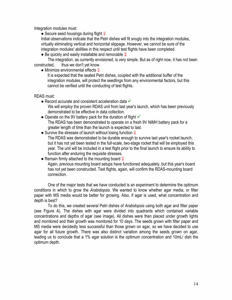
Integration modules must:
● Secure seed housings during flight Initial observations indicate that the Petri dishes will fit snugly into the integration modules, virtually eliminating vertical and horizontal slippage. However, we cannot be sure of the integration modules' abilities in this respect until test flights have been completed. ● Be quickly and easily installable and removable
The integration, as currently envisioned, is very simple. But as of right now, it has not been constructed, thus we don't yet know.
● Minimize environmental effects It is expected that the sealed Petri dishes, coupled with the additional buffer of the integration modules, will protect the seedlings from any environmental factors, but this cannot be verified until the conducting of test flights.
RDAS must:
● Record accurate and consistent acceleration data We will employ the proven RDAS unit from last year's launch, which has been previously demonstrated to be effective in data collection.
● Operate on the 9V battery pack for the duration of flight The RDAS has been demonstrated to operate on a fresh 9V NiMH battery pack for a greater length of time than the launch is expected to last.
● Survive the stresses of launch without losing function The RDAS was demonstrated to be durable enough to survive last year's rocket launch, but it has not yet been tested in the full-scale, two-stage rocket that will be employed this year. The unit will be included in a test flight prior to the final launch to ensure its ability to function after enduring the requisite stresses.
● Remain firmly attached to the mounting board Again, previous mounting board setups have functioned adequately, but this year's board has not yet been constructed. Test flights, again, will confirm the RDAS-mounting board connection.
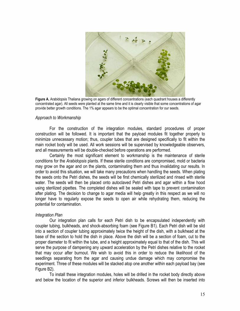
One of the major tests that we have conducted is an experiment to determine the optimum conditions in which to grow the Arabidopsis. We wanted to know whether agar media, or filter paper with MS media would be better for growing. Also, if agar is used, what concentration and depth is best? To do this, we created several Petri dishes of Arabidopsis using both agar and filter paper (see Figure A). The dishes with agar were divided into quadrants which contained variable concentrations and depths of agar (see image). All dishes were then placed under growth lights and monitored and their growth was monitored for 10 days. The seeds grown with filter paper and MS media were decidedly less successful than those grown on agar, so we have decided to use agar for all future growth. There was also distinct variation among the seeds grown on agar, leading us to conclude that a 1% agar solution is the optimum concentration and 10mL/ dish the optimum depth.
15
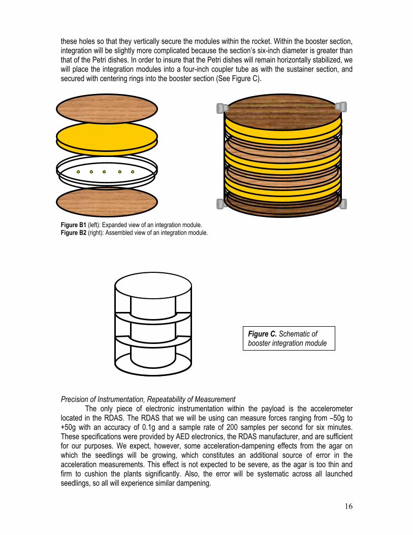
Figure A. Arabidopsis Thaliana growing on agars of different concentrations (each quadrant houses a differently concentrated agar). All seeds were planted at the same time and it is clearly visible that some concentrations of agar provide better growth conditions. The 1% agar appears to be the optimal concentration for our seeds. Approach to Workmanship For the construction of the integration modules, standard procedures of proper construction will be followed. It is important that the payload modules fit together properly to minimize unnecessary motion; thus, coupler tubes that are designed specifically to fit within the main rocket body will be used. All work sessions will be supervised by knowledgeable observers, and all measurements will be double-checked before operations are performed. Certainly the most significant element to workmanship is the maintenance of sterile conditions for the Arabidopsis plants. If these sterile conditions are compromised, mold or bacteria may grow on the agar and on the plants, contaminating them and thus invalidating our results. In order to avoid this situation, we will take many precautions when handling the seeds. When plating the seeds onto the Petri dishes, the seeds will be first chemically sterilized and rinsed with sterile water. The seeds will then be placed onto autoclaved Petri dishes and agar within a flow hood using sterilized pipettes. The completed dishes will be sealed with tape to prevent contamination after plating. The decision to change to agar media will help greatly in this respect as we will no longer have to regularly expose the seeds to open air while rehydrating them, reducing the potential for contamination. Integration Plan Our integration plan calls for each Petri dish to be encapsulated independently with coupler tubing, bulkheads, and shock-absorbing foam (see Figure B1). Each Petri dish will be slid into a section of coupler tubing approximately twice the height of the dish, with a bulkhead at the base of the section to hold the dish in place. Above the dish will be a section of foam, cut to the proper diameter to fit within the tube, and a height approximately equal to that of the dish. This will serve the purpose of dampening any upward acceleration by the Petri dishes relative to the rocket that may occur after burnout. We wish to avoid this in order to reduce the likelihood of the seedlings separating from the agar and causing undue damage which may compromise the experiment. Three of these modules will be stacked atop one another within each payload bay (see Figure B2). To install these integration modules, holes will be drilled in the rocket body directly above and below the location of the superior and inferior bulkheads. Screws will then be inserted into
16
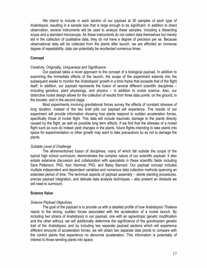
these holes so that they vertically secure the modules within the rocket. Within the booster section, integration will be slightly more complicated because the section’s six-inch diameter is greater than that of the Petri dishes. In order to insure that the Petri dishes will remain horizontally stabilized, we will place the integration modules into a four-inch coupler tube as with the sustainer section, and secured with centering rings into the booster section (See Figure C).
Figure B1 (left): Expanded view of an integration module. Figure B2 (right): Assembled view of an integration module. Precision of Instrumentation, Repeatability of Measurement The only piece of electronic instrumentation within the payload is the accelerometer located in the RDAS. The RDAS that we will be using can measure forces ranging from –50g to +50g with an accuracy of 0.1g and a sample rate of 200 samples per second for six minutes. These specifications were provided by AED electronics, the RDAS manufacturer, and are sufficient for our purposes. We expect, however, some acceleration-dampening effects from the agar on which the seedlings will be growing, which constitutes an additional source of error in the acceleration measurements. This effect is not expected to be severe, as the agar is too thin and firm to cushion the plants significantly. Also, the error will be systematic across all launched seedlings, so all will experience similar dampening.
Figure C. Schematic of booster integration module
17
We intend to include in each section of our payload at 30 samples of each type of Arabidopsis, resulting in a sample size that is large enough to be significant. In addition to direct observation, several instruments will be used to analyze these samples, including a dissecting scope and a standard microscope. As these instruments do not collect data themselves but merely aid in the collection of qualitative data, they do not have a degree of precision per se. Because observational data will be collected from the plants after launch, we are afforded an immense degree of repeatability; data can potentially be recollected numerous times. Concept Creativity, Originality, Uniqueness and Significance Our payload takes a novel approach to the concept of a biological payload. In addition to examining the immediate effects of the launch, the scope of the experiment extends into the subsequent weeks to monitor the Arabidopsis' growth in a time frame that exceeds that of the flight itself. In addition, our payload represents the fusion of several different scientific disciplines – including genetics, plant physiology, and physics – in addition to rocket science. Also, our distinctive rocket design allows for the collection of results from three data points: on the ground, in the booster, and in the second stage. Most experiments involving gravitational forces survey the effects of constant stresses of long duration, instead of the two brief jolts our payload will experience. The results of our experiment will provide information showing how plants respond to sudden acceleration forces, specifically those of rocket flight. This data will include traumatic damage to the plants directly caused by the flight, as well as possible long term effects. If we find that the stresses of a rocket flight such as ours do indeed yield changes in the plants, future flights intending to take plants into space for experimentation or other growth may want to take precautions so as not to damage the plants. Suitable Level of Challenge The aforementioned fusion of disciplines, many of which fall outside the scope of the typical high school curriculum, demonstrates the complex nature of our scientific payload. It also entails extensive discussion and collaboration with specialists in these scientific fields including Sara Patterson, PhD, Ken Hammel, PhD, and Betsy Barnard. Our payload concept includes multiple independent and dependent variables and numerous data collection methods spanning an extended period of time. The technical aspects of payload assembly – sterile planting procedures, precise payload integration, and delicate data analysis techniques – also present an obstacle we will need to surmount. Science Value Science Payload Objectives The goal of the payload is to provide us with a detailed profile of how Arabidopsis Thaliana reacts to the strong, sudden forces associated with the acceleration of a rocket launch. By including two strains of Arabidopsis in our payload, one with an agravitropic genetic modification and the other without, we will additionally determine the significance of the gravitropism genetic trait of the Arabidopsis, and by including two separate payload sections which will experience different amounts of acceleration forces, we will obtain two separate data points to compare with the control plants that experience no abnormal acceleration. This information is potentially of interest to those sending plants into space.
18
Payload Success Criteria The following are considered benchmarks for payload success: • A statistically significant number (30 per strain per section) of seedlings are able to provide
viable data points. • The RDAS records accurate acceleration data. • The different payload sections reach distinct accelerations, with the second stage reaching a
much higher acceleration. • All Petri dishes remain sealed, undamaged and sterile during flight and recovery. • No seedlings are harmed in preparation for flight or extraction from payload sections. • Integration modules remain intact for future use in experimental flights. Experimental Logic, Approach, and Method of Investigation Our primary Science Payload Objective is to ascertain the effects of sudden and significant acceleration on Arabidopsis Thaliana. We intend to determine this by subjecting both wild-type and agravitropic seedlings to these forces under measured and controlled conditions, and comparing the immediate effects, subsequent growth, and ultimate development of these sample plants to those of comparative samples of seedlings kept at normal conditions on the ground. Specifically, we intend to carry out several types of results analysis on each sample, and to test ten or more seedlings with each method. These methods include: microscopic root analysis, wherein a plant’s root growth is examined; stained microscopic analysis, where a stain is applied that indicates the presence of a specific gene, DR5-GUS, in a naturally occurring root-growth-promoting chemical prior to analysis; and long-term developmental analysis, where seedlings are transplanted to appropriate conditions where they can grow to maturity and data points such as height, leaf count, and root length will be tracked. In order to obtain a more detailed profile of acceleration force effects on Arabidopsis, our method of investigation is to test two genetically differing sets of plants and to test both in three different acceleration settings (including the control set). We can, in this way, compare data sets to evaluate the importance of the genetic component of Arabidopsis acceleration, and to analyze whether there exists a proportionality between acceleration forces and plant development, or whether plants will be affected by these forces as long as the acceleration exceeds a certain threshold. Variables and Controls, Test and Measurement Variables Independent variables: • Acceleration duration & intensity • Presence of gravitropism trait in Arabidopsis strain Dependant variables: • Physical changes in plant structure Controls • Age of plants at launch • Plant growth conditions (light exposure, temperature) • All materials (agar, Petri dishes, nutrient solution) • Specific strains of plants • Time of removal and return to normal conditions of all plants post-recovery • Planting technique
19
Test Measurements • Microscopic root analysis • Number of branches, length of root, thickness of root • Post-stain microscopic root analysis: Location, density, longevity or growth-promoting auxin in
roots • Long-term development analysis: Height, leaf count, and root length profiles over long period
of time Relevance of Expected Data, Accuracy & Error Analysis Our data will provide results that could affect plans to send plants into space for research in Earth orbit and beyond. They will also provide relevant details on the reaction of the agravitropic strain of Arabidopsis Thaliana to sudden acceleration forces compared to the wild type. As previously stated, we intend to measure a set of data points that will be considered statistically significant. We will ensure the safe recovery of a satisfactory number of seedlings via the fine-tuning of our payload units before the final launch. We will continue to consult with Prof. Sara Patterson, Ph. D, of the University of Wisconsin-Madison Department of Horticulture while we conduct results analysis after our flight. Experiment Process Procedures Exactly one week prior to the launch date, we will prepare 16 Petri dishes (8 wild type, 8 agravitropic) each containing 15 seedlings. These will then be placed under light and allowed to grow undisturbed until the launch date. The day of the launch we will select the 12 dishes that appear to have the most robust Arabidopsis populations and arbitrarily divide them into the three testing groups. Two of these groups will be installed into the integration modules that will then be placed into each of the rocket sections and secured. Following launch, the payload components will be recovered and brought back to the staging area where the experiment Arabidopsis will be removed from the payload capsule. Following the launch, we will begin data collection. As soon as we are able, we will take measurements of the plants regarding their root length and thickness and branching using a dissecting scope to serve as a baseline for future observations. One week and two weeks after the launch we will take subsequent observations on these traits. Also, one week after launch we will perform the auxin root growth analysis. To do this we will expose the plants to a special stain which, because of a marker gene inserted in the plant’s genome, will cause the cells containing active auxin, an indicator of root growth, to change color. Lastly, we will eventually transplant the Arabidopsis to soil so that we can observe any changes as the plants grow to maturity. Safety Data Demonstrating That Risks Are Very Near Acceptable Levels Risks for the payload are very acceptable. Preliminary plantings on agar have demonstrated germination rates of close to 90%. Also, the agar has been shown to be able to successfully sustain the plants for multiple weeks. 0% of Arabidopsis planted on agar have been contaminated. Preliminary Risk Assessment, Failures and Mitigations There are several risks associated with our payload, however all are easily mitigable. First, there is the possible of random traumatic stress being exerted on the components of the payload. It
20
is possible that the stresses of flight may cause a Petri dish to crack, resulting in contamination of the dish. We have determined this to be very unlikely; crude stress tests performed on the Petri dishes showed them to be extremely resilient to vertically oriented forces. In the event that damage does occur, there will be several other Petri dishes present on the rocket which will create a degree of redundancy that will allow us to achieve a partial success. This level of redundancy also mitigates concerns about the possibility of seedlings separating from the agar (causing random traumatic damage to the seedlings) during negative acceleration after motor burnout, as does the use of padding foam placed above each dish. During dish preparation, there is a possibility of the seedlings not developing properly to the growth stage at which we wish to launch them. This could be caused by contamination of the seeds by mold or bacteria, or simply by unexpected seed sterility. We will work to avoid this by preparing several extra dishes of seedlings beyond the nine (three in each stage, three control) that are required for a trial of the experiment. In this way, in the event of some portion of the dishes being unusable, we will have the option of substituting a healthier set of plants. We also intend to preempt contamination concerns by practicing aseptic technique when plating the plants (see Approach to Workmanship). Environmental Concerns In the context of the payload's potential impact on the environment, safety will not be an issue. It is difficult to imagine a way in which the payload could pose a hazard; much of the payload is potentially edible. There are however several significant ways in which the environment can impact the payload. As already mentioned, it is imperative that we retain the sterility of the Arabidopsis' environment in order to prevent contamination such as mold which would invalidate our results (see “Approach to Workmanship”).
21
III) Outreach & Project Plans Our plans to solicit additional community support are progressing nicely. We are very excited that our website is up and running. We have added SLI documents, team photos, and useful links to the website. Our progress is documented both by our documents and the photos in our photo galleries. Our visitor list includes individuals from around the globe. Our technological endeavors don’t stop at the website. We are also distributing multimedia CDs with all our sponsorship requests. Pictures, documents, and video footage is included on these CDs for the viewing pleasure of our audiences. We anticipate a flood of community supporters when the feature documentary about rocketry at West High makes its television debut. We hope that the first showing will be in the coming month. The primary way we engage younger students in rocketry is through our school’s TARC program. The older students who are on the SLI team mentor the younger TARC participants. This relationship extends beyond the material science lab to forming lasting friendships. The feedback our younger students have expressed is exceptional. They enjoy having upperclassmen guide them and show them the “tricks of the trade”. They rely on our SLI team for not only academic support, but emotional guidance as well.
22
IV) Rocket Program Sustainability Update Since the submission of PDR we have filled two grant applications with the intention of securing funds for the next year. The first application (Rotary grant) has not been chosen by the school for the second round of evaluation. The second application is still pending.
We maintain our good relationships with several departments of the University of Wisconsin, namely physics, horticulture/plant science, meteorology/atmospheric sciences and astronomy departments. The SLI students are working with the advisors at the UW on different parts of their projects and also received numerous small but helpful donations in the form of supplies and spare parts.
We have found a nice support for our group at Governor Nelson State Park, our new launch site. The park officers waived our entry fees for the whole year and they are also exploring a possibility of engaging some of the students in nature conservation programs.
We are exploring a possibility of a symbiotic relationship with a non-profit organization Glass Eye Productions (based in central Europe) that specializes in providing pro-bono support in the fields of photography, web/graphics design and electronic publishing. Our other SLI team will be receiving a DSLR camera from Glass Eye Productions for their infrared aerial photography project.
We also have a commercial sponsor, Camera Co. that is supporting our other SLI team and already provided a material support for our last years SLI team. We are about to launch a sponsorship-finding campaign, since our documentary from the last year is already finished and being aired.
Just recently we have started formulating the content of the high power rocketry program for the students that will run out of SLI possibilities in the next year. We have contacted Wallops Island and White Sands rocket ranges and we hope to secure an opportunity to spend a weekend and launch at one or the other location at the end of the school year 2007.
The cooperation between TARC teams and SLI teams tightened recently as all teams share both the workshop and the launch location (Governor Nelson State Park, Waunakee, WI). Most of our SLI students are TARC veterans and thus they are interested in seeing how they successors approach the TARC objectives. The TARC students have an opportunity to see SLI projects progressing and talk with the older students, which is quite beneficial to all the groups involved.