The Effect of Doppler Frequency Shift, Frequency Offset of ... · The Effect of Doppler Frequency...
16
r- -- -- - - - - --. "- - "-- _ .. _-- - - - - - - NASA/TM-2001-210595 2M / D7Y 1J 7 529'1YD fJ fl L // The Effect of Doppler Frequency Shift, Frequency Offset of the Local Oscillators, and Phase Noise on the Performance of Coherent OFDM Receivers FuqinXiong Cleveland State University, Cleveland, Ohio Monty Andro Glenn Research Center, Cleveland, Ohio March 2001 https://ntrs.nasa.gov/search.jsp?R=20010049375 2018-06-04T14:33:02+00:00Z
Transcript of The Effect of Doppler Frequency Shift, Frequency Offset of ... · The Effect of Doppler Frequency...

r- ~ ---- - - - - --."- - "-- _ .. _-- - - - - - -
NASA/TM-2001-210595 2M/D7Y1J 7
529'1YD fJ flL
//
The Effect of Doppler Frequency Shift, Frequency Offset of the Local Oscillators, and Phase Noise on the Performance of Coherent OFDM Receivers
FuqinXiong Cleveland State University, Cleveland, Ohio
Monty Andro Glenn Research Center, Cleveland, Ohio
March 2001
https://ntrs.nasa.gov/search.jsp?R=20010049375 2018-06-04T14:33:02+00:00Z
, L
The NASA STI Program Office .. . in Profile
Since its founding, NASA has been dedicated to the advancement of aeronautics and space science. The NASA Scientific and Technical Information (STI) Program Office plays a key part in helping NASA maintain this important role.
The NASA STI Program Office is operated by Langley Research Center, the Lead Center for NASA's scientific and technical information. The NASA STI Program Office provides access to the NASA STI Database, the largest collection of aeronautical and space science STI in the world. The Program Office is also NASA's institutional mechanism for disseminating the results of its research and development activities. These results are published by NASA in the NASA STI Report Series, which includes the following report types:
• TECHNICAL PUBLICATION. Reports of completed research or a major Significant phase of research that present the results of NASA programs and include extensive data or theoretical analysis. Includes compilations of significant scientific and technical data and information deemed to be of continuing reference value. NASA's counterpart of peerreviewed formal professional papers but has less stringent limitations on manuscript length and extent of graphic presentations.
• TECHNICAL MEMORANDUM. Scientific and technical findings that are preliminary or of specialized interest, e.g., quick release reports, working papers, and bibliographies that contain minimal annotation. Does not contain extensive analysis.
• CONTRACTOR REPORT. Scientific and technical findings by NASA-sponsored contractors and grantees.
• CONFERENCE PUBLICATION. Collected papers from scientific and technical conferences, symposia, seminars, or other meetings sponsored or cosponsored by NASA.
• SPECIAL PUBLICATION. Scientific, technical, or historical information from NASA programs, projects, and missions, often concerned with subjects having substantial public interest.
• TECHNICAL TRANSLATION. Englishlanguage translations of foreign scientific and technical material pertinent to NASA's mission.
Specialized services that complement the STI Program Office's diverse offerings include creating custom thesauri, building customized data bases, organizing and publishing research results ... even providing videos.
For more information about the NASA STI Program Office, see the following:
• Access the NASA STI Program Home Page at http://www.sti.nasa.gov
• E-mail your question via the Internet to [email protected]
• Fax your question to the NASA Access Help Desk at 301-621-0134
• Telephone the NASA Access Help Desk at 301-621-0390
• Write to: NASA Access Help Desk NASA Center for AeroSpace Information 7121 Standard Drive Hanover, MD 21076

NASA/TM-2001-210595
The Effect of Doppler Frequency Shift, Frequency Offset of the Local Oscillators, and Phase Noise on the Performance of Coherent OFDM Receivers
Fuqin Xiong Cleveland State University, Cleveland, Ohio
Monty Andro Glenn Research Center, Cleveland, Ohio
National Aeronautics and Space Administration
Glenn Research Center
March 2001

Acknow ledgments
The author wishes to thank Mr. Monty Andro of the Digital Communications Technology Branch, NASA Glenn Research Center, for providing the information in Table 2 and other information. The author also wishes to thank
Mr. Binh Nguyen of the same branch for critiques and discussions regarding the paper.
NASA Center for Aerospace Information 7121 Standard Drive Hanover, MD 21076 Price Code: A03
Available from
National Technical Information Service 5285 Port Royal Road Springfield, VA 22100
Price Code: A03
Available electronically at http: //gltrs.grc.nasa.gov I GLTRS

The Effect of Doppler Frequency Shift, Frequency Offset of the Local Oscillators, and Phase Noise on The Performance
of Coherent OFDM Receivers
Fuqin Xiong Cleveland State University
Cleveland, Ohio 44115
Monty Andro, National Aeronautics and Space Administration
Glenn Research Center Cleveland, Ohio 44135
Abstract This paper first shows that the Doppler frequency shift affects the frequencies of
the RF carrier, subcarriers, envelope, and symbol timing by the same percentage in an OFDM signal or any other modulated signals. Then the SNR degradation of an OFDM system due to Doppler frequency shift, frequency offset of the local oscillators and phase noise is analyzed. Expressions are given and values for 4-, 16-,64-, and 256-QAM OFDM systems are calculated and plotted. The calculations show that the Doppler shift of the D3 project is about 305 kHz, and the degradation due to it is about 0.01 to 0.04 dB, which is negligible. The degradation due to frequency offset and phase noise of local oscillators will be the main source of degradation. To keep the SNR degradation under 0.1 dB, the relative frequency offset due to local oscillators must be below 0.01 for the 16QAMOFDM. This translates to an offset of 1.55MHz (0.01x155 MHz) or a stability of 77.5ppm (0.01x155 MHz/20GHz) for the D3 project. To keep the SNR degradation under O.ldB, the relative linewidth (~) due to phase noise of the local oscillators must be below 0.0004 for the 16QAM-OFDM. This translates to a linewidth of 0.062 MHz (0.0004 x 155MHz) of the 20 GHz RF carrier. For a degradation of IdB, ~=0.04 , and the linewidth can be relaxed to 6.2 MHz.
I. Introduction
An orthogonal frequency division multiplexing (OFDM) signal can be written as N , - i
v(t) = L ~ cos( (OJ + cp;) (1) ;=1
where Ai, COj, and <Pi are the amplitude, angular frequency, and phase of the ith subcarrier. Ns is the number of subcarriers. In order for the subcarriers to be orthogonal to each other, j. = (Oi /2n must be integer multiples of l/2T[l, p. 90, 101][2], where T is the symbol period of the data, and j. are spaced in frequency by Rs = 1fT (if all <Pi are the same, i.e.,
NASA/TM-200 1-21 0595 1

coherent, the spacing can be multiples of 1/2T, and the minimum spacing is l/2T). Usually Ii are chosen as integer multiples of the symbol rate Rs = lIT.
If the signal is amplitude shift keyed (ASK), Ai is determined by the data, and <1>i is a random phase uniformly distributed in [-n, n]. If the signal is phase shift keyed (PSK), Ai is constant, and <1>i is determined by the data. Therefore the above is a general form of the OFDM signal in the baseband. It is called the baseband OFDM signal because this ignal is usually modulated on a higher frequency carrier before transmission. However,
this signal can also be transmitted directly, without further frequency conversion (e.g., the system depicted in [3]).
The signal v(t) is modulated on a RF carrier with a frequency Ie for transmission:
s(t) = 2v(t )cos OJJ
N , - i
= 2 L.A; cos(OJ;f + ¢; )coswct ;=0
N , -i
= L. A;{cos[(wc +OJ)+¢J+cos[(wc +OJ;/-¢J} (2) ;=0
where We = 2n Ie. The phase of the carrier has been assumed to be zero without loss of generality. The amplitude of the carrier is set to 2 to simplify the analysis later. A single sideband transmission is enough to convey the information imbedded in Ai and <Pi. Assume upper sideband is used, the transmitted signal is
N , -i
s(t)= L. A; cos[(Wc + OJ;} + ¢;] (3) ;=0
If the lower sideband is used, the transmitted signal is
N, -i
s(t)= L. A;cos[(Wc -W)+¢J (4) ;=0
II. Doppler Frequency Shift
Doppler shift ID is proportional to the frequency I of the electromagnetic wave in propagation, and is given by
vf f. = - '- cosa (5) c
where Vr is the relative speed between the transmitter and the receiver, I is the carrier frequency, c is the speed of light (3 X 10⁸m/s), and a. E [0, n] is the angle of the velocity vector. The maximum/D happens when a. = 0.
vi maX(jD) = - (6)
c
NASAfTM-2001 -210595 2
If the speed is in unit of kilometers per hour, (5) can be changed to
vi fD = cosa
3.6 x 3x l08 (7)
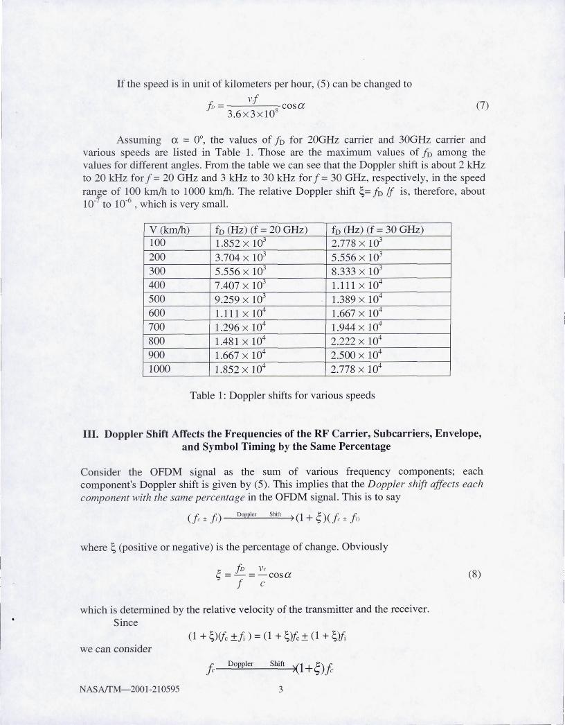
Assuming a = 0°, the values of fo for 20GHz carrier and 30GHz carrier and various speeds are listed in Table 1. Those are the maximum values of fo among the values for different angles . From the table we can see that the Doppler shift is about 2 kHz to 20 kHz for f = 20 GHz and 3 kHz to 30 kHz for f = 30 GHz, respectively, in the speed range of 100 km/h to 1000 km/h. The relative Doppler shift ~= fo If is, therefore, about 10-7 to 10-6
, which is very small.
v (km/h) fo (Hz) (f = 20 GHz) fD (Hz) (f = 30 GHz) 100 1.852 x 10³ 2.778 X 10³
200 3.704 X 10³ 5.556 X 10³
300 5.556 X 10³ 8.333 X 10³
400 7.407 X 10³ 1.111 X 10⁴
500 9.259 X 10³ 1.389 X 10⁴
600 1.111 X 10⁴ 1.667 X 10⁴
700 1.296 X 10⁴ 1.944 X 10⁴
800 1.481 X 10⁴ 2.222 X 10⁴
900 1.667 X 10⁴ 2.500 X 10⁴
1000 1.852 X 10⁴ 2.778 X 10⁴
Table 1: Doppler shifts for various speeds
III. Doppler Shift Affects the Frequencies of the RF Carrier, Subcarriers, Envelope, and Symbol Timing by the Same Percentage
Consider the OFDM signal as the sum of various frequency components; each component's Doppler shift is given by (5). This implies that the Doppler shift affects each component with the same percentage in the OFDM signal. This is to say
where ~ (positive or negative) is the percentage of change. Obviously
j; fD Vr ':> =-=-cosa
f c (8)
which is determined by the relative velocity of the transmitter and the receiver. Since
(1 + ~)(jc ±fi ) = (1 + ~)fc ± (1 + ~)fi we can consider
fc __ D~o~pp~le_r __ S~h=m~~l+~)fc
NASA/fM-200 1-210595 3
and
Doppler Shift -7 (1 + ~ ) .fi
That is, the Doppler shift affects the carrier frequency fe and the subcarrier frequencies Ii by the same percentage ~. The Doppler shifts are
J:.{: v,fc f D,. = '-:JJ C = -cos ex (9)
c
and
J: v,/; fD , = ..;f ; = -cos ex (10)
c Thus the OFDM signal with Doppler shift is
Ns-l
s'(t) = LA; cos[(1+~)(wc +m) t+¢J ;=0
;=0
(11)
Consider Ai COS [(1 +~) COit+ <Pi] as the envelope of the carrier COS [(1 +~)(()et] and similarly for the second term, this expression shows that the Doppler shift affects the carrier frequency and the envelope frequency by the same percentage. This conclusion can be extended beyond OFDM signal to any modulated signal.
The clock timing is derived from the symbol rate Rs = Iff in the modulated signal. Since each ·subcarrier frequency is an integer multiple of Rs, when the subcarrier frequency changes by a percentage ~ due to Doppler shift, Rs changes by the same percentage ~. This conclusion also applies to any modulated signal.
In conclusion, Doppler shift affects the frequencies of the RF carrier, subcarriers, envelope, and symbol timing by the same percentage ~.
The fact that all subcarrier frequencies change by the same percentage destroys the orthogonality between subcarriers. This is because the separations between subcarriers are no longer mRs, (m integer). Instead, they become (1 + ~)mRs . The OFDM system performance degradation due to frequency offset caused by Doppler shift and other sources will be discussed in Section V.
The Doppler shift rate I'D, which is the rate of changes in Doppler shift due to the changes in relative velocity, can be derived as follows. Rewrite (5) as
fo (t) = v,. (t)f cosex(t) c
where the Doppler shift and the velocity (v(t) and a (t» are functions of time 1. Taking the derivative we have
NASA/fM-2001-21 0595 4

i"D (t) = I ~ (t) = 1. [v;. (t) cos aCt) - v,. (t)a ' (t) sin a(t)] c
= 1. [a ,. (t)cosa(t) - v,. (t)a' (t)sina(t)] (12) c
where a,. is the relative acceleration rate, From (5) we know that the maximum 10 happens when a = 0, To determine at
what angle maximum ro happens, we fix the acceleration rate ar(t) and rewrite (12) as
rD(t) = I [a, cosa(f)- V,.(t)a'(t)sina(t)] c
The maximum of this can be found by letting its derivative be zero, and is at aCt) = a = O.
max(rD
) = a,. 1 c
(13)
IV. Doppler Shifts of the OFDM Signal for the D3 Project
In the proposed D3 project, the OFDM modem developed in this branch will be put on the space shuttle and at a ground station, There is only a down link with a carrier frequency of 19.035 GHz. The maximum relative speed is 4811.00 m/s and the maximum relative acceleration is 168.00 m/s2, In Table 2, the maximum Doppler shifts are calculated using (6) and the Doppler shift rates are calculated using (13).
Sym. Description Value Units Source Vr maximum relative velocity 4811.00 m/s Dean Schrage's
(seen by ground terminal) analysis a,. maximum relative acceleration 168.00 m/sL Dean Schrage's
(seen by ground terminal) analysis c speed of light 3.00E+08 m/s standard
Ie source frequency (carrier) 19.035 GHz project spec.
IDe maximum carrier Doppler shift 305.26 kHz calculated rDe maximum carrier Doppler shift rate 10.66 kHz calculated
Id source frequency (data clock) 155.52 MHz project spec.
IOd maximum data clock Doppler shift 2.49 kHz calculated
rOd maximum data clock Doppler shift 0.09 kHz calculated rate
±frequency variation required 16.04 ppm calculated
Table 2: Worst case Doppler shifts for D3 Project
From the table we can see that the maximum Doppler shift is about 300 kHz in the carrier frequency and 2.5 kHz in the clock frequency. In both cases the relative shift is only
NASA/TM-2001-210595 5

The symbol rate of the 622 Mbps 16QAM-OFDM modem is about 60 Mbps per channel when coding is considered. Thus the channel separation is also 60 MHz, the relative Doppler shift (relative to the channel separation) in carrier is
E = 305.26 x l03
::::: 5 x lO-3
60 x 106 (14)
This is the number that determines the performance degradation in the coherent OFDM demodulator.
v. Performance Degradation of Coherent OFDM Modem Due to Doppler Frequency Shift, Frequency Offset of Local Oscillators, and Phase Noise
Performance degradation of coherent OFDM modem due to channel frequency offset, including Doppler frequency shift and frequency offset of local oscillators in the receiver, is analyzed in [4] and [5]. In both papers, the OFDM signals are assumed to be generated by the inverse discrete Fourier transform (IDFT) and demodulated by the discrete Fourier transform (DFT). Also, channel phase noise is included in the channel models in both papers. But there are some different assumptions in the two papers. We will point out them in the following description of the major results of these papers.
In [4], the channel is modeled by a complex transfer function Hk for the kth subcarrier and a frequency offset £ for all subcarriers, where £ is relative to the data symbol rate Rs = 1fT (A WGN is also present). And £ includes the frequency offsets due to Doppler shift and the local oscillator (LO) frequency error. Recall that we have demonstrated that each subcarrier suffers from the same percentage but different values of Doppler shift. This model is therefore not accurate. However, when the Doppler shift in the carrier (fDe) is not tracked and the offset in the LO (6.fLO) is not compensated for, this model is approximately correct. In this case the total offset for each subcarrier after down conversion is
6.f = f Dc + fD; + 4fLO
where fDe and fDi are given by (9) and (10), respectively. It is clear that fDe » fDi , since f e »fi. Thus
6./; == f Dc + 6.f LO = 6.f That is, the offset is approximately independent of subcarriers. The relative offset
is thus approximately independent of subcarriers. Based on this model, the signal-to-noise ratio (SNR) at the output of the DFT at
the OFDM receiver is found as
SNR>Ec sinnE - 1 ( )
?
- No m:. 1 + 0.5947 ( E;{v 0 }Sin m:. Y ,lEI < 0.5 (15)
NASA{fM-2001-210595 6

•
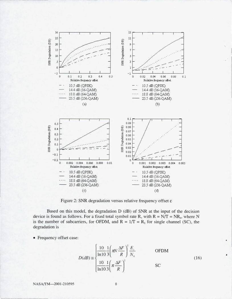
At BER = 10-6 the SNR is 10.5, 14.4, 18.8, and 23 .5 dB for QPSK, 16- QAM, 64-QAM, and 256-QAM respectively. The degradations for these SNRs are shown in Figures 1 and 2. Figure 1 shows how SNRs degrade as relative offset increases. Figure 2 shows the direct degradations versus the relative offset.
30
25
20
~ 15
f2 '" 10
5
0
-5 0 0 .1
10.5 dB (QPSK) 14.4 dB (16-QAM) 18 .8 dB (64-QAIvI) 23.5 dB (256-QAIvI)
0.::1 0.3 0.4
Figure 1: SNR versus frequency offset £
0 .5
Return to the D3 project. If the offset includes only the Doppler shift, the maximum relative offset £::::: 5 X 10⁻³. 16-QAM is the modulation used in the 622-Mbps D3 OFDM system. It is seen from Figure 2 (d) that for £ ::::: 5 X 10⁻³ the degradation is below 0.04 dB. Therefore, the SNR degradation, hence the BER pelformance degradation , caused by the Doppler shift is negligible in D3 OFDM system. This happens because the symbol rate (60 Mbps) is very high. If the symbol rate is lower, say, 10 Mbps, then the relative offset is higher: £ ::::: 0.03. Consequently, the SNR degradation of 16-QAM would be around 1 dB for SNR,= 14.4 dB. Further lowering the symbol rate will cause the degradation even bigger.
Similar results are reported in [5], where the channel is modeled by a time-varying phase 8(t) caused by either a carrier offset between the receiver and transmitter carrier, or the phase noise of these carriers. In the first case, 8 (t) is deterministic and equals 2n~t + 80, where M is the carrier offset. In the latter case, 8(t) is modeled as a Wiener process for which E[8 (t)] = 0 and E[8 (t+to) -8 (to)f = 4nPltl, where 8 denotes the one-sided 3 dB linewidth of the Lorentzian power density spectrum of the free-running carrier generator.
NASAffM-2001-210595 7
.-.. -.~----
30
i£' 25
e, 20 \OJ
.~ 15
1 10 A ~ 5 U>
0
-5 0
0.5 i£'
0.4 e,
.! 0.3
1 0.2
A 0.1
~ 0 U>
-0.1
-0 .2 0
0 .1 02 0 .3 0.4 O ~
R.ehm'l! frequency oIfset
10.5 dB (QPSK) 14.4 dB (16-QAlvI) 18.8 dB (64-QAIvI) 23.5 dB (256-QAlvI)
(a)
"" - " ,
0.002 0 .004 0.006 0.008 0.0 1 R.e~ frequency oIfset
10.5 dB (QPSK) 14.4 dB (16-QAIvI) 18.8 dB (64-QAIvI) 23.5 dB (256-QAlvI)
(c)
13r---,---.---.---.---~
-1L---L---~--~--~--~
o 0.02 0.04 0 .06 0.08 0 .1 R.ehm'e frequelliY oIfset
10.5 dB (QPSK) 14.4 dB (16-QAlvI) 18.8 dB (64-QAlvI) 23.5 dB (256-QAlvI)
(b)
0.1 r----,-----r,----,---,----. 0.09
i£' 0.08 e, g 0.D7 .tj 0 .06
1 0.05
A 0.04
~ 0.03 ~ 0.02
0.01
0.001 0.002 0 .003 0 .004 0.005 R.e~ frequency oIfset
10.5 dB (QPSK) 14.4 dB (16-QAIvI) 18.8 dB (64-QAIvI) 23.5 dB (256-QAIvI)
(d)
Figure 2: SNR degradation versus relative frequency offset £
Based on this model, the degradation D (dB) of SNR at the input of the decision device is found as follows . For a fixed total symbol rate R, with R = NfT = NRs, where N is the number of subcarriers, for OFDM, and R = 1fT = Rs for single channel (SC), the degradation is
• Frequency offset case:
D(dB) ==
10 l(nN M)2 Es InlO 3 R No
~!(nM')2 InlO 3 R
OFDM
(16)
SC
NASArrM-2001-210595 8
------- --~ -
•

For OFDM, the degradation is proportional with EJNo, but it is not the case for SC. For both OFDM and SC, the degradation is proportional with the square of the frequency offset. For OFDM, the degradation is also proportional with the EJNo, and with the square of the number of subcarriers.
• Phase noise case
OFDM
D (dB) == (17)
SC
For both OFDM and SC, the degradation is proportional with EJNo, and the linewidth ~ .
For OFDM, the degradation is also proportional with the number of subcarriers. From (16) and (17) it is seen that the degradation (in dB) of OFDM due to
frequency offset or phase noise is N2Es/No or N times greater than that of SC, respectively. Using the subcarrier spacing (Rs), the OFDM part of (16), (17) can be written as
( )
2 101M Es
D(dB) == {-- TC- -In 10 3 Rs N o
OFDM (18)
and
D(dB) == ~~(4TC~)~ OFDM (19) 1010 60 Rs N o
respectively. In the expressions, M/Rs and ~/Rs are relative frequency offset and linewidth versus the subcarrier spacing, respectively.
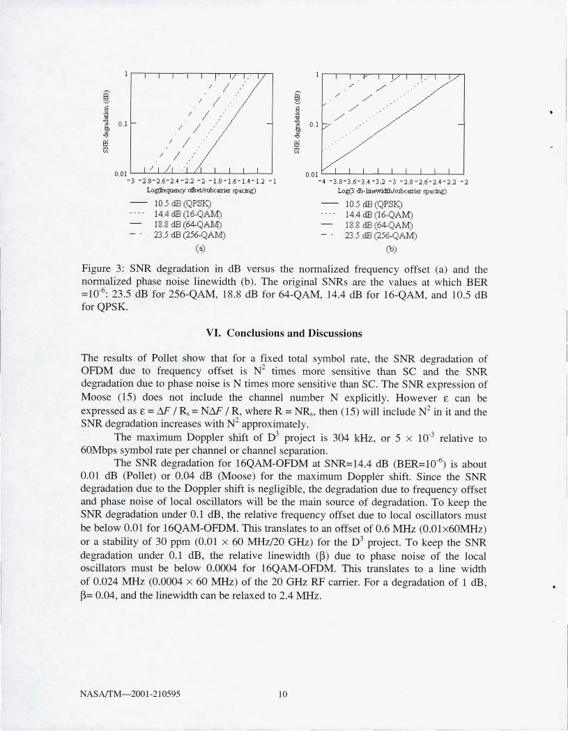
Some numerical results for (18) and (19) are plotted in Figure 3. For 16-QAM, which is the modulation used in the 622-Mbps D3 OFDM system, from the figure it can be seen that the degradation due to Doppler shift £.= M/R :::::5x 10⁻³ (log £. = -2.3) is about 0.01 dB (This is similar to the results in Figure 2(d)). However, if the relative phase noise linewidth is also 5 x 10⁻³, then the degradation is much larger: about 1.0 dB . This means the degradation is more sensitive to the phase noise.
NASAfTM-2001-210595 9
LogOrequ.en£y offset/rubcmier spacing)
10.5 dB (QPSK) 14.4 dB (16-QAM) 18.8 dB (64-QAM) 23.5 dB (256-QAIvI)
(a)
,/ /" ./
./ ./
o .0 1 '---"-----..L.---'-----'----L----'------''---''------'---' -4 - 3.8 - 3,6-3,4 -3.2 - 3 -2 .8 -2,6-2,4-;U -2
LO;;l..3 db-lilw.vi.dth/rubcmier spacing)
10 .5 dB (QPSK) 14.4 dB (16-QAM) 18.8 dB (64-QAlvI) 23.5 dB (256-QAM)
(b)
Figure 3: SNR degradation in dB versus the normalized frequency offset (a) and the normalized phase noise linewidth (b)_ The original SNRs are the values at which BER =10-6
: 23_5 dB for 256-QAM, 18_8 dB for 64-QAM, 14.4 dB for 16-QAM, and 10.5 dB for QPSK.
VI. Conclusions and Discussions
The results of Pollet show that for a fixed total symbol rate, the SNR degradation of OFDM due to frequency offset is N2 times more sensitive than SC and the SNR degradation due to phase noise is N times more sensitive than Sc. The SNR expression of Moose (15) does not include the channel number N explicitly. However £, can be expressed as £, = M' / Rs = NM' / R, where R = NRs, then (15) will include N2 in it and the SNR degradation increases with N2 approximately.
The maximum Doppler shift of D3 project is 304 kHz, or 5 x 10⁻³ relative to 60Mbps symbol rate per channel or channel separation.
The SNR degradation for 16QAM-OFDM at SNR=14.4 dB (BER=1O-6) is about 0.01 dB (Pollet) or 0.04 dB (Moose) for the maximum Doppler shift. Since the SNR degradation due to the Doppler shift is negligible, the degradation due to frequency offset and phase noise of local oscillators will be the main source of degradation. To keep the SNR degradation under 0.1 dB, the relative frequency offset due to local oscillators must be below 0.01 for 16QAM-OFDM. This translates to an offset of 0.6 MHz (0.01x60MHz) or a stability of 30 ppm (0.01 x 60 MHz/20 GHz) for the D3 project. To keep the SNR degradation under 0.1 dB, the relative linewidth (~) due to phase noise of the local oscillators must be below 0.0004 for 16QAM-OFDM. This translates to a line width of 0.024 MHz (0.0004 x 60 MHz) of the 20 GHz RF carrier. For a degradation of 1 dB, ~= 0.04, and the linewidth can be relaxed to 2.4 MHz.
NASAfTM-2001-210595 10

•
References
[1] Xiong, F., Digital Modulation Techniques, Artech House, Boston/London, 2000
[2] van Nee, R. , and R. Prasad, OFDM For Wireless Multimedia Communications, Artech House, Boston/London, 2000 .
[3] Weinstein, S. B . and P. M. Ebert, "Data transmiSSIOn by frequency-division multiplexing using the discrete Fourier transform," IEEE Trans. on Commun., vol. 19, no. 5, Oct. 1971, pp. 628-634.
[4] Moose, P. H., "A technique for orthogonal frequency division multiplexing frequency offset correction," IEEE Trans. on Commun. , vol. 42, no. 10, Oct. 1994, pp. 2908-2914.
[5] Poilet, T. et aI, "BER Sensitivity of OFDM systems to carrier frequency offset and Wiener phase noise," IEEE Trans. on Commun. , vol. 43, no. 2/3/4, Feb./Mar./Apr. 1995, pp. 191-193.
NASArrM-2001-210595 11

---------
REPORT DOCUMENTATION PAGE Form Approved
OMB No. 0704-0188
Public reporting burden for Ihis collection of informalion is estimated to average 1 hour per response. including the time for reviewing instruclions, searching existing data sources, galhering and maintaining Ihe data needed, and completing and reviewing the collection of information . Send comments regarding this burden estimate or any other aspect of this collection of information, including suggestions for reducing this burden, to Washington Headquarters Services, Directorate for Information Operat ions and Reports, 1215 Jefferson Davis Highway, Suite 1204, Arlington, VA 22202·4302, and to the Office of Management and Budget , Paperwork Reduction Project (0704·0188), Washington, DC 20503.
1 . AGENCY USE ONLY (Leave blank) 12. REPORT DATE 13. REPORT TYPE AND DATES COVERED
March 2001 Technical Memorandum 4. TITLE AND SUBTITLE 5. FUNDING NUMBERS
The Effect of Doppler Frequency Shift, Frequency Offset of the Local Oscillators, and Phase Noise on the Perfolmance of Coherent OFDM Receivers
6. AUTHOR(S) VVU-755-08-OB-OO NCC3-809
Fuqin Xiong and Monty Andro
7. PERFORMING ORGANIZATION NAME(S) AND ADDRESS(ES) 8. PERFORMING ORGANIZATION REPORT NUMBER
National Aeronautics and Space Administration John H. Glenn Research Center at Lewis Field E-12553 Cleveland, Ohio 44135-3191
9. SPONSORINGIMONITORING AGENCY NAME(S) AND ADDRESS(ES) 10. SPONSORINGIMONITORING AGENCY REPORT NUMBER
ational Aeronautics and Space Administration Washington, DC 20546-0001 ASA TM-2001-210595
11. SUPPLEMENTARY NOTES
Fuqin Xiong, Cleveland State University, Department of ECE, 1983 E. 24th Street, Cleveland, Ohio 44115-2403, and Monty Andro, NASA Glenn Research Center. Responsible person, Monty Andro, organization code 5650, 216-433-3492.
12a. DISTRIBUTION/AVAILABILITY STATEMENT 12b. DISTRIBUTION CODE
Unclassified -Unlimited Subject Category: 32 Distribution: Nonstandard
Available electronically at http://gltrs.grc.nasa.goy/GLTRS
This publication is available from the NASA Center for AeroSpace lnformation, 301-621-0390. 13. ABSTRACT (Maximum 200 words)
This paper first shows that the Doppler frequency shift affects the frequencies of the RF carrier, subcarriers, envelope, and symbol timing by the same percentage in an OFDM signal or any other modulated signals. Then the SNR degradation of an OFDM system due to Doppler frequency shift, frequency offset of the local oscillators and phase noise is analyzed. Expressions are given and values for 4-, 16-, 64-, and 256-QAM OFDM systems are calculated and plotted. The calcula-tions show that the Doppler shift of the D3 project is about 305 kHz, and the degradation due to it is about 0.01 to 0.04 dB , which is negligible. The degradation due to frequency offset and phase noise of local oscillators will be the main source of degradation. To keep the SNR degradation under 0.1 dB , the relative frequency offset due to local oscillators must be below 0.01 for the 16 QAM-OFDM. This translates to an offset of 1.55 MHz (0.0Ix 155 MHz) or a stability of 77.5 ppm (0.01x 155 MHzl20 GHz) for the D3 project. To keep the SNR degradation under 0.1 dB , the relative linewidth (~) due to phase noise of the local oscillators must be below 0.0004 for the 16 QAM-OFDM. This translates to a linewidth of 0.062 MHz (0.0004x I55 MHz) of the 20 GHz RF carrier. For a degradation of 1 dB, ~ = 0.04, and the linewidth can be relaxed to 6.2 MHz.
14. SUBJECT TERMS 15. NUMBER OF PAGES
l7 Doppler 16. PRICE CODE
A03 17. SECURITY CLASSIFICATION 18. SECURITY CLASSIFICATION 19. SECURITY CLASSIFICATION 20. LIMITATION OF ABSTRACT
OF REPORT OFTHIS PAGE OF ABSTRACT
Unclassified Unclassified Unclassified
NSN 7540-01-280-5500 Standard Form 298 (Rev. 2-89) Prescribed by ANSI Std. Z39-18 298-102
I I I
j