The Effect of Car Mass on (Internal and External) Safety with A Case ...
110
The Effect of Car Mass on (Internal and External) Safety with A Case Study on Concept Family Car By Sinan MIZIKACI A Dissertation Submitted to the Graduate School in Partial Fulfillment of the Requirements for the Degree of MASTER OF INDUSTRIAL DESIGN Department: Industrial Design Major: Industrial Design izmir Institute of.Technology izmir, Turkey June, 1999
Transcript of The Effect of Car Mass on (Internal and External) Safety with A Case ...
The Effect of Car Mass on (Internal and External) Safetywith A Case Study on Concept Family Car
By
Sinan MIZIKACI
A Dissertation Submitted to theGraduate School in Partial Fulfillment of the
Requirements for the Degree of
MASTER OF INDUSTRIAL DESIGN
Department: Industrial DesignMajor: Industrial Design
izmir Institute of.Technologyizmir, Turkey
June, 1999
We approve the thesis of Sinan MIZIKACI.
/4Y ('I. z:~::---;:,~J~ .Assist. Prof. Yavuz SECKiN
Supervisor
Department of Industrial Design
............. ~~.
Assist. Prof. Dr. Can OZCAN
Department of Industrial Design
Assist. Prof. Dr. Onder ERKARSLAN
Department of Industrial Design
rof. Dr. ~OIenKiPoz
Department of Industrial Design
.C>.?.~.., ..G1?· em
Assoc. Prof. Dr. Giine~ GUR
Department of City and Regional Planning
(JfP;}~~~Assist. Prof. Yavuz SECKiN
Department of Industrial Design
Head' of Department
Date and Signature
;?t/tJ1!9''11IlMIR YUKSEK TEKNOlOJi ENSTiTUS"j
REKTORlUGU
Kuffipnane ve Dokiimo osyon Daire B~k.
ACKNOWLEDGMENT
I would be incessantly gratified by~
Putting my heartfelt feeling as thankyous to all members of Department of Industrial Design.
I would like to profoundly express;
My gratitude to my thesis advisor for his immense practical helps, Asist. Prof Dr. Yawz
SE<;KiN, Guvnor of Department ofIndustrial Design,
I am eternally grateful to;
My family for their morally and aptly contributions,
I would like to give a thank to;
My sincere, broadminded friend Serkan YILMAZ with wishing to be m succeSSIve
achievements in his lifetime for ever.
IllMIR YUKSH: T~~NOL~Ji~ftlSnrUSU iii! REKTORLUGU
Viitfiphaoe ve Doko tasyon Daire B~k.
ABSTRACT
Transportation means are always of importance to people due to their functions. Originally,
a vehicle in terms of a means of transportation has been thought as only a device what takes
people from one place to another point. But with considering both occupant being
transported and vehicle means of transportation since their inextricable relations, vehicle has
become significantly considerable within its design.
Prodded by industrial revolution, especially after introducing the first mechanized mode of
vehicle in 1769, the technological advantages have highly intensely been used in automotive,
and also now. Primarily, within that advantages, even all efforts providing for retention of
vehicle during a crash to protect occupants from the injury risk have been zeroed in on for
only the one objective: to design vehicles with a high capability of safety.
In this thesis, We consider that people in scale unit as family for vehicle design of the need.
Environment for the family vehicle is thought a place encircling metropolis wherein the
people as grouped lives out and wishing that it was so pleasant place, just a few miles away
from the city, taking advantages of working at home.
Moreover, we are in making a think of vehicle design for family that ought to contain the
conventional signs more within global perceptiveness as small, but not compressed down
since the generation becomes huger in size by years, and finally has enough space of interior
regarding ergonomical and anatomical requirements. Under the definitions for creating the
concept family vehicle within limits, the project aims to present most apropos model, and
assumes to allow the person to drive and to move on it in safest position.
In this paper, in the light of above, we will set out to clarify the safety features of vehicle
structure for Family Vehicle, and with respect to that each connective parameter in the
boundary of freedom will be clarified.
iv
oz
U1a~lmaraylan i~levlerinden otiirii insanlar iyin daima onemli olagelmi~lerdir. Onceleri, arab a
ula~lm araCl olarak sadece insanlan bir yerden diger bir noktaya gotiiren basit bir duzenek
olarak du~unulurdu. Fakat, ta~lmlan yolcu ve de ula~lIDaraCl arasmdaki giiylu ili~ki dikkate
almdlgmda araba, tasarum ile birlikte hayti onem kazandl.
Endustriyel devrimin verdigi durtii , ozellikle de 1769 ydmda arabanm makinala~mlrm~ ilk
modelinin ytkmasmdan sonra, teknolojik olanaklar ~imdi de oldugu gibi otomotiv sektoriinde
hayti yogun olarak kullamldl. Oncelikle kaza sure since arabamn direncini artlrmaya yonelik,
yolculan yaralanma riskinden koruyacak olan butiin yabalar teknolojik olanaklan da
kullanarak yalmzca bir amay iyin dikkate almdl: yiiksek giivenlik kabiliyetine sahip bir arab a
tasarlamak.
Bu tezde, aray tasanrm iyin insanlarm aile olyeginde olacagrnt kabul ediyoruz. Aile arabasl
iyin du~unulen yevre; ana ~ehri yevreleyen, insanlarm gruplar halinde ya~ad1~ alandrr ve
~ehirden birkay mil uzakta evde yah~mamn avantajlarllll ta~lyan oyle bir alamn sempatik
olacaglffi umuyoruz.
Ustelik, aile iyin kiiltiirel, yoresel, y~am biyimi izleri ta~lyan, kiiyuk fakat, insanlarm
bedenen yillara gore daha da geti~ecegi tezi ile baslk olmayan, ergonomik ve anatomik
ihtiyaylan kar~dayacak yeterli iy hacime sahip, genel kabullere dayall araba tasanrm
du~uncesini kurgulamaktaytZ. Kavramsal aile arabasmm olu~turulmasi iyin geryekci
tammlamalara dayanarak, proje en uygun modeli sunmaYl amaylar, ve insanlarin en emniyetli
~ekilde surmesini ve seyahat etmesini sagIayacagrnt varsayar.
Bu tezde, yukandakilerin l~l~nda, aile arabasma yonetik aray yaplslmn giivenlik ozelliklerini
netle~tirecegiz, ve bu yeryevede irdelenen her baglaytcl faktore belli bir esneklik payt
iyerisinde aylkllk kazandrraca~.
IIMIR YUKSEK TfkNOlOJi fNsTlrOslJ IREKTORlUGU
; KOtfiphane va OokiJman osyon Doire B~k.
v

LIST OF FIGURES
CHAPTERl
Figure 1.1. A view of Peugeot 206 five-door model.
(http://www.jcsnell. co.uk/range/206/206 p. gif).
Figure 1.2. A view of Peugeot 206 three-door model.
(http://www.jcsnell. co.uk/range/206/206 _lx.gif).
Figure 1.3. A view ofDaewoo Matiz.
(http://www.symetry.com/Matiz/matiz. gif).
Figure 1.4. Average weight of person considering height factor.
CHAPTER 2
Figure 2.1. Test configurations to simulate crash modes.
(Stucki, Sheldon L. & Hollowell, William T., Determination of Frontal Offset Test
Conditions Based on Crash Data, NHTSA R&D, United States, paper number 98-81-0-02,
page 6).
Figure 2.2. Schematic of Hybrid III Test Dummy.
(http://www.ftss.com/h-3_95thyhoto.jpg).
Figure 2.3. Schematic of Side Impact Test Dummy (BIOSID Dummy).
(http://www.ftss.com/sid_IIsyhoto.JPG).
Figure 2.4. Moderate and more severe injury risk to possible crash modes.
Figure 2.5. Fatality injury risk to possible crash modes.
Figure 2.6. Risk to a general body region group (MIS 2).
Figure 2.7. Risk to a general body region group (MIS3).
Figure 2.8. Injury risk to the leg locations (MIS2).
Figure 2.9. Injury risk to the leg locations (MIS3).
Figure 2.10. Schematic of the probable trajectory of crushing.
Figure 2.11. Schematic of possible flow of impact forces.
vi
Figure 2.12. Test configuration of vehicle for side impact.
(Federal Motor Vehicle Safety Standards, Standard No. 214, Side Impact Protection, USA,
1998, page 606).
Figure 2.13. Loading device positioning and its application towards the doors.
(Federal Motor Vehicle Safety Standards, Standard No. 214, Side Impact Protection, USA,
1998, page 601).
Figure 2.14. Windshield protection zone (All dimensions in mm).
(Federal Motor Vehicle Safety Standards, Standard No. 219, Windshield Zone Intrusion,
USA, 1998, page 646).
CHAPTER 3
Figure 3.1. Constructing elements by direction of impact.
(Federal Motor Vehicle Safety Standards, Standard No. 207, Seating Systems, USA, 1998,
page 489).
Figure 3.2. Front inertia load to the seating reference point.
(Federal Motor Vehicle Safety Standards, Standard No. 207, Seating Systems, USA, 1998,
page 490).
Figure 3.3. Rear inertia load to the seating reference point.
(Federal Motor Vehicle Safety Standards, Standard No. 207, Seating Systems, USA, 1998,
page 490).
Figure 3.4. Schematics of seats of Dainty Vehicle.
Figure 3.5. Removable label on dash or sun visor.
(Federal Motor Vehicle Safety Standards, Standard No. 208, Occupant Crash Protection,
USA, 1998, page 531).
Figure 3.6. Label on child seat where child's head rests.
(Federal Motor Vehicle Safety Standards, Standard No. 213, Child restraint systems, USA,
1998, page 597).
Figure 3.7. Identification and illustration of controls.
(Federal Motor Vehicle Safety Standards, Standard No. 101, Controls and Displays, USA,
1998, page 187).
vii

Figure 3.8. Identification and illustration of displays.
(Federal Motor Vehicle Safety Standards, Standard No. 101, Controls and Displays, USA,
1998, page 188).
Figure 3.9. Interrelationship between requirements in compliance with safety.
Figure 3.10. Schematic of effect of suspension system in Family Car in side-bisected view.
Figure 3.11. Schematic of vibration factor in the car.
CHAPTER 4
Figure 4.1. Color range of Dainty Car.
Figure 4.2. Graphic of Dainty Car rear window value.
Figure 4.3. Graphic of Dainty Car CD value.
Figure 4.4. Final structure of the project.
Figure 4.5. Final view of the project.
Figure 4.6. An experience in car design evolution.
Figure 4.7. An experience in car design evolution.
viii

LIST OF TABLES
CHAPTER 4
Table 4.1. Specifications of Dainty Car.
Table 4.2. Exterior fitments of Dainty Car.
Table 4.3. Interior fitments of Dainty Car.
ix
TABLE OF CONTENTS
COVER PAGE , 1
SIGNATORY PAGE .ii
ACKNOWLEDGMENT 111
ABSTRACT '" .iv
bz v
LIST OF FIGURES VI
LIST OF TABLES .. , IX
TABLE OF CONTENTS x
INTRODUCTION , 1
CHAPTER 1 '" 7
1.1. REVIEW OF TITLE 7
1.1.1. IDENTIFICATION OF FAMILY CAR 7
1.1.2. LIGHT CAREV ALUATION 11
1.1.2.1. ECONOMIC PROVISIONS OF LOW-MASS 13
1.1.3. AN OVERVIEW OF FAMILY INCOME
IN PARALLELING CAR OWNERSlllP 13
CHAPTER 2 14
2.1. LIGHT CAR SAFETY IN PERSPECTIVE , 14
2.1.1. MASS AND SIZE ENFORCEMENTS ON A CAR 14
2.2. OCCUPANT CRASH PROTECTION 15
2.2.1. CRASH ENVIRONMENT AND INJURY 16
2.2.2. DISTRIBUTION OF CRASH TYPES 16
2.2.3. SIMULATION OF CRASH ENVIRONMENT 18
2.2.3.1. DUMMY RECOGNITION 18
2.2.3.2. INJURY RISK BY SIMULATION 21
x
2.2.3.3. BODY REGION INJURY ASSESSMENT 22
2.2.3.4. RECOMMENDATIONS 25
2.2.4. SAFETY AND THE COMPUTER 25
2.2.5. TESTS 28
CHAPTER 3 SAFETY SYSTEMS 38
3.1. CONCEPT OF PASSIVE PROTECTION 38
3.1.1. RESTRAINT SYSTEMS 39
3.1.2. SIGNALS 49
3.1.3. IDENTIFICATION OF CONTROLS AND DISPLAYS 51
3.1.4. FLAMMABILITY 56
3.2. CONCEPT OF ACTIVE PROTECTION '" '" 56
3.2.1. AIRBAGS 57
3.2.2. CONTROLS AND DISPLAYS 58
3.2.3. ADVANCED SYSTEMS PROVIDING FOR CAR SAFETY 59
3.2.3.1.I.T.S 60
3.2.3.1.1. AUTOMATIC STEERING USING IMAGE INFORMATION 61
3.2.3.1.2. CRASH AVOIDENCE SySTEMS 62
3.3. REQUIREMENTS IN COMPLIANCE WITH SAFETY 65
3.3.1. COMFORT 65
3.3.2. STREAMLININGS FOR NOISE, FUEL CONSUMPTION, AND COST 68
CHAPTER 4 PORING OVER CASE 71
4.1. AN OVERVIEW OF PROJECT 71
4.2. STRUCTURE OF CAR 78
4.2.1. DISTRIBUTION OF CAR STRUCTURE 78
4.2.1.1. BODy 78
4.2.1.1.1. AERODYNAMICS 79
4.2.1.1.2. STRUCTURAL CONCEPTS 82
4.2.1.1.3. BODY INBOARD 84
xi
4.2.1.2. ENGINE 86
4.2.1.2.1. EXPECTATIONS 86
4.3. EXPERIENCES IN CAR DESIGN EVOLUTION 95
CONCLUSION .................................................................................. 98
GLOSSARY 100
REFERENCES .................................................................................. 105
END 108
xii

INTRODUCTION
Going down in history, human beings have been intervened with unexpected technologies to
achieve the controlling of the environmental factors. Curbing in the name of shifting the
superiority of nature to the side of the human mass by processing the objects gotten from the
raw sources and utilizing them for the use of specific neediness supports the convergence
with the human kind and the environment. Shaping, forming, and functioning from first
antecedence models to the modem designs, those have been assumed the credence of safety
in forms, usages, symbols or adding the useability a livening up property.
Safety in vocabulary gathers the meanings of state of being safe from the harm and danger
and for objects safety is out of unwilling properties (Dictionary of Collins Cobuild, 1995).
Designs for products on account of product risk preliminarily affix the requirements onto
itself and in that process, the more requirements are in need, the more technological
opportunities are used. The contradiction of much-to-much perceptiveness has lasted up
past three decades. We think it is clearly wrong. The concept is resulted from the thought of
the way in which the complexity requires great attention, as a result so much malfunctions in
products. Barely, it could be thought as an equation. Raw equation supplied with concept,
material, paradigm, function and form that all give properties as they are, but all directly
effects the safety hardly enough or much. For such products, development period of
transportation means could be counted as a peak example.
Starting with using the pure vehicle mechanizm around 3500 B.C. by ancient Sumerian
Civilization using flat structures had been mounted on wheels, subsequently it had been
followed by use of horses that remained till the mid of 18th century. In all uses since the
means just for only carrying the loads the intense of safety requirements has stayed at a level
not being considered in designs. Profoundly, utilizing the technological developments from a
different perspective, approaching the nature hesitantly and the wars propelled the human
being to provide the equipments with rough, vulgar, rigid geometry with heavy materials.
1

That thought has reflected transportation means in two significant eras of the car history
could be defined as:
• Early Cars era between 1769-1885,and
• First Modem Cars era between 1885-1914.
a. Early Cars first introduced and designed were steam-propelled cars in terms of self
propelled concept. That period has nonetheless an important role of developing the modem
car.
Very first known car designed and introduced by, a military engineer, Nicolas Cougnot in
1769,in France. It was fuelled the steam and could achieve the speed only up to 6 kilometres
per hour, so far heavy design to practical use. After first experienced the same model
produced in 1771,however the machine ran well made a crash to the wall because of driver's
performance degradation. That event recorded as the first motorcar accident causing by
human being.
Orderly, in 1807 Isaac de Rivaz designed the first internal combustion engine using the
hydrogen and oxygen to generate the needy energy was a gas driven engine. And after
completing development of the engine, it designed the first internal combustion car. Finally,
the year 1813it developed a car 6 meters long and about one ton weight.
Through the 1860there was no considerable event, only Jean Etienne Lenoir patented very
successful two-stroke gas engine capable of attaining the peak up to 3kmph, in Belgium.
In 1865,The Red Flag Act stated by manufacturers of horse-driven coaches and in the end,
based on the evidence of its weight causing damage, especially for roads, the use of steam
car gradually discarded and propelled to use the turnpikes. Eventually, development of those
car modes completely discouraged, except some occasion experiences.
2
And finally, in 1876 patented four-stroke engine were developed by Nikolaus August Otto
containing intake valve, piston, fuel-air mixture, cylinder, spark plug, compressed mixture,
mixture ignites, exhaust valve, burned gases.
b. First Modern Cars
Second era in the car history begins with introducing the first petrol engine in 1885. Since the
car were produced very congruent to the car being run, it is known as, and therefore
backgrounds of some of nowadays best known car companies like Rennault and Ford leads
to back in 1900.
In its historical development, after August Otto, Karl Benz improved and designed the first
modem car implemented and stabled on the three-wheeled with four-stroke engine concept.
In 1886, Gotlieb Daimler fitting the four-stroke engme onto a horse-driven coach, and
created the first four-wheeled motorcar.
The concept of the personal little-low-mass car at first began at first decade of the 20th
century. Ransome Eli Olds introduced the assembly line concept for mass-produce of the car
and the first little-low-mass car produced as its prototype name of Oldsmobile Gas Buggy.
After two important eras in car history, added family concept for small cars, The Miki City
Car founded in the late of '50s by Rodolfo Bonetto could be accepted mid-outclass model.
If the historic trends considered, the one of aims of study is to make assembly of advantages
of each era and to introduce all those in the concept of personal transportation system as
Family Car.
3
In use of advantages, the study and project are directed in those ways:
a. Concept of study
After producing first car, a variety of designs are introduced to the user. Each all takes the
different social concerns, different shapes in bodies, aesthetic proportions, safety, and so on.
Almost all, out of safety, have so improved and designs became so close each other.
Moreover, nowadays, since the technology in use very congruent on world scale for
producing a car, ability to innovate or create a completely different structure in car design is
reduced. But, although the term safety is considered in designs, yet improved enough. So, it
could be counted as a raw area for designers and, even by reason of annihilating the
potentially impelled harms onto occupant as a result of smash hits, it could allow to do so
much things in that area. Also, it could help the designers to shape the car in a completely
different side of the innovation and directs the efforts to the property of the product safety.
b. Concept of project
Also accepting above, additionally designing a car instead of much-to-much act of seeing,
extreme in constant for conceptual safety. It is marginal applying a new object for each
safety requirement. But it resists the comfort, increase loaded weight and energy
consumption, and so on. But in our criteria, if the result reflects the safety being efficient or
not, it should gather and be define the portion of each factor. Thus, the different factors
being coincided with each, the result or what it is expected from the safety gets the peak.
Reasons for choosing mean defined in the name of Family Car, cultural habits reflected to
the project. Considering the strong bond in our nation in term of family structure, statistical
results, and customer wishes accounted for the tendency of car model to be selected. It is
considered to turn conceptual approaching of the safety to viability, applicability at the end.
And the thoughts of compact but comfort, light gains frenetic, small but smart, simple but
4

means more, make something extra-special refute all blandness in innovation, quality and
emotion will be the secondary aims for the project,
Criteria for Family Car study are as:
• Compatibility, in mass, structure, stiflhess, performance and technological
opportunities for safety, and
• Useability, the secondary aims of the project will be reflected to the criterion of
useability, since thinking of utilizing all in terms of adding innovation to the design. Such
as condensing the control buttons in size and numbers, or making the dashboard smaller
but designing the buttons bigger signs the usability. Small but smart will obtain the
advantages of being mobile system, especially in jammed area.
The project considered the system automation in the mid-point between car and driver. So,
not the portion of use the car almost electronically, but with respect to touching gives
feelingof being safety and restricts the degradation of harmony between them, the portion of
driver-use is considered as primary gain. Rated electronic usage added system thinking of
being more advantageous to the steering safety.
The term safety involved the design criteria to produce the solutions not just in technical
proportions and also in human-based factors. And all actions gathered are named vehicle
safety. So far, all the obligations, legislative regulations, and requirements have been put in a
role of defining the vehicle safety reason in documents but, expect some successfully studies
in worldscale, have not gotten more since those only present an cursory-look through the
problem. We are making a think of constructing the problems around the criteria in order for
us what we want the design to reply on conceptual project.
This thesis will be a research on Light-Dainty Vehicle with a case study of Family Car.
Added general additives in first and second chapter thought to provide the people more
5
familiar the safety problem. Later on, in sequence chapters, by expressing the technical
assessments concerning car structure on both inner and outer space of a car and spreading
the project renderings into whole titles is to understand connection of design with related
subjects. Referring new technologies and manufacturing techniques for producing of
complete bodies in last chapter is to show the project suitable for producing by advanced
methods and techniques.
Overall thesis, comparing and critisizing is to reach the solution to be able to undertake by
putting in processing to show how promising is a structure or developed system aimed at its
all components. To the end, by all considerations based on the technical assessments and
society, We will imagine and outlook of all done so far.
In the thesis explainings and direction of the implementing subjects since so wide in its
category, each explained case is accepted as source, and methods in complete car design.
And therefore, all chapters would be the base to the last one.
6

CHAPTERl
1.1. REVIEW OF TITLE
1.1.1. IDENTIFICATION OF FAMILY CAR
A car as very innovative product, in apple pie order, arrangement of about ten thousand
individually separated articles as finite elements into a whole that runs. That best
arrangement has taken place in our life as a result of the combination of technical stake with
the need. Based upon that kind of view, we clarify a car to be a result of purely social
requirements in paralleling technical achievements.
Pretended to see, the need for ingenuity of the car in which design process gains messages.
If the designer treats as was user, stating the problem becomes familiar us, and touches
muchmany aspects in our life.
Creating a car with the family concept results in one of model in category of personal
transportation means. So, shaping, defining solid and voids on that, wishing reflecting the
spirit in term of a car with feelings, expressing individuality differentiate from others. The
individuality leaves, sharing common habits, properties of lifestyle of family and related
habitsbecome current. As mentioned, Turkish family lifestyle contains being together, living
together for a prolonged time and creating the time to share coming from having strong
kernel structure. If average number of family population of six reflected to the design, it
needs much more space than the need of worldscale acceptance. The wind of change on
world, global perceptiveness, and becoming the living much similar to the others by
accepting the same technology everywhere also impel a car design to be congruent to its all
classas in other.
7
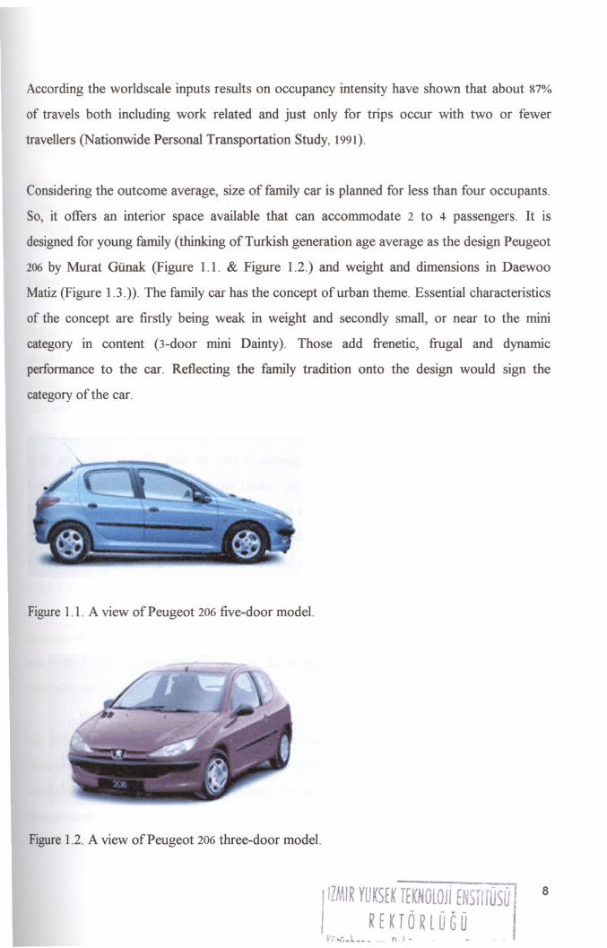
According the worldscale inputs results on occupancy intensity have shown that about 87%
of travels both including work related and just only for trips occur with two or fewer
travellers (Nationwide Personal Transportation Study, 1991).
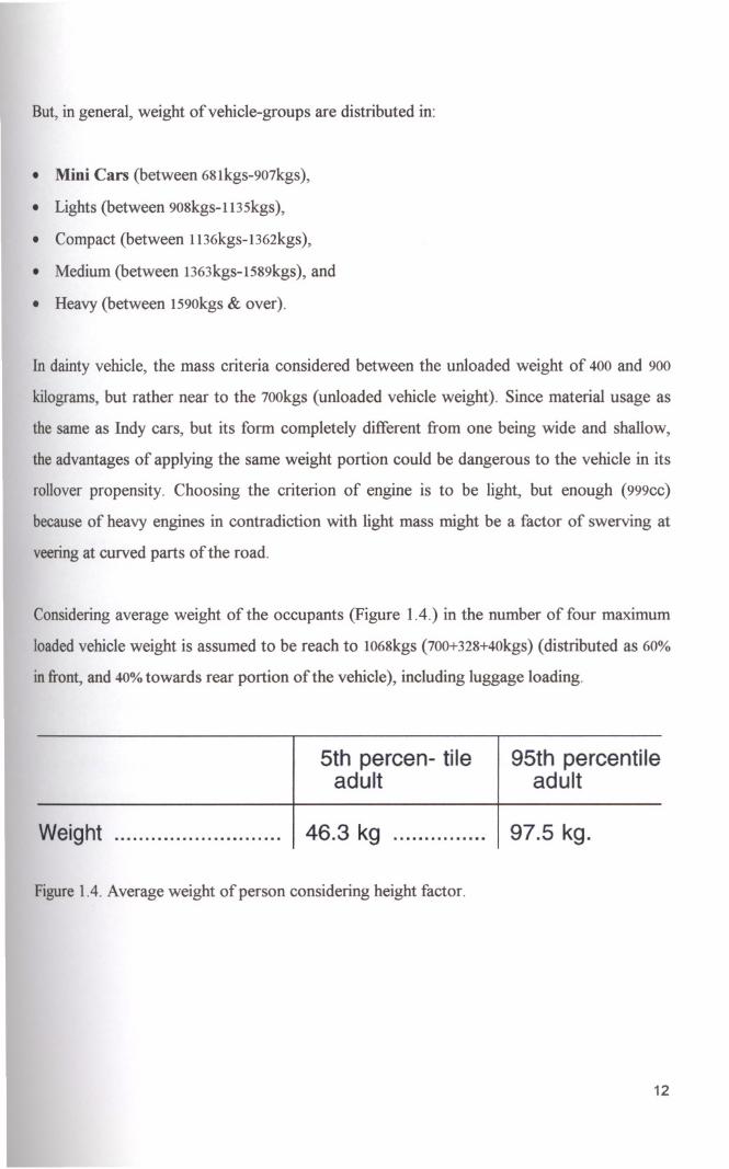
Considering the outcome average, size of family car is planned for less than four occupants.
So, it offers an interior space available that can accommodate 2 to 4 passengers. It is
designed for young family (thinking of Turkish generation age average as the design Peugeot
206 by Murat Giinak (Figure 1.1. & Figure 1.2.) and weight and dimensions in Daewoo
Matiz (Figure 1.3.». The family car has the concept of urban theme. Essential characteristics
of the concept are firstly being weak in weight and secondly small, or near to the mini
category in content (3-door mini Dainty). Those add frenetic, frugal and dynamic
performance to the car. Reflecting the family tradition onto the design would sign the
category of the car.
Figure 1.1. A view of Peugeot 206 five-door model.
Figure 1.2. A view of Peugeot 206 three-door model.
IIIMIR YUKSEK TEKNOlOJi EtJ5T1rOSO J 8
i '._ R E K TOR lUG 0 IL·l;.~l.~~•... ILl - _ ..

Figure 1.3. A view ofDaewoo Matiz.
Brand name as Dainty for the project is chosen since it gathers the meaning of weak in
weight, small, delicate, pretty, and special. Hence, as thought one word was able to contain
a number of meanings based the term of simple means more. Critisizing existing models like
The Model T by Ford Company, first founded in 1908, We thought, it is an example for
sourcing to design the car with the model Volvo 880 having the best safety properties in
body as a stiff chassis. But, as 1963 Volkswagen Beetle literally means person's car, by
Ragtop Sedan, could be base to the Dainty car as the luggage being mixed to the simple
form, and its being compact. For that reason, it could be considered as outclass model in its
category. Specialty of two-door term is reflected as countered of the wheel is not integrated
to the side edge of front sided-doors. Optimal drag factor of the form is 0.21 (Chapter 4,
4.2.1.1.1. aerodynamics, page 80).
In many circumstances, the project is considered as an example the Beetle's exterior form in
side with a deformation of front hood to the form being integrated with windshield in the
view of a soft slope.
So, person's transportation means could be converted easily to the family car. The only
thing is to make the luggage area rated enough to the store the occupants' equipments. For
smallones it is difficult to set that property. To gain the alternative space secret luggage is
thought under the each seating system. When occupant or driver hold up the cushion would
take the advantage of placing the small things that makes untidy in interior side of the car
9

compartment. Also, it could save the laden luggage reducing by a third. In the project, the
structure of the luggage area gains more space partly or completely foldable rear-bench seat.
Design is thought up for travelling, shopping, bazaar, and for vacation.
Containingthe small volume could be seen as disadvantage for those of car. But, shifting the
rate of solid and void through the side of latter, the disadvantage is deflected and advantage
may occur. That makes enough space of interior volume regarding ergonomical and
anatomical requirements considering the occupants' persons. Also, being tightly in small
area disturbs the comfort, but it gains comradely effects between each person. Why?
Although the persons that have no strong relationship or friendship, the car provides them to
get on with each other. Hence small size presents a long variety of advantages to the users,
not only in technical properties but also in social concerns.
In our proposal, the concept not only for sale to the side of the family, it also based on
offeringand recovery service using a parking system by installing a genuine network of small
parking stations. The stations would be under ground. To hire it, a subscription system
curbedby a computerized network functioning using a smart card.
If all successfully done, the project could be also replaced and condensed all category of
personal transportation means into one model, and therefore We would not be surprised to
see the car fundamentally intensely express the concept of family in whole category in the
next future.
By the way, all new achievements as well as innovations resulted for that otherwise conjured
up ideal idea mentioned above takes the automobile industry to produce one upscale model
as familycar or its various types.
10

1.1.2. LIGHT CAR EVALUATION
Downsizing, especially in '70s, seemed to have been driven likely via changes in ownership
and two-car families than economic factors. However, after the petroleum shortages
emerged in relation to OPEC oil embargo, manufacturers are launched on foraging for
developing more promising transportation systems. As a result, the low-mass car design
became spreading on worldscale.
That kind of private car being mentioned as an alternative is known as the most effective
transportation system on the land. All category of such vehicle imitated as LTV stands for
Light Vehicle or LMV under the name of Low Mass Vehicle.
Ability to freely and individually move people is the precedence link in design for such
category of that car. But the primary tradeoff for light, or low-mass car is impelled risk of
harm in a collision. Thus, should those kinds of ramifications were able to be remedied by
emphasizing innovative safety hallmarks such as visually impressive driver information
systems, advanced car control and crash avoidance systems, and attractive car layouts and
stylingin combination with material extension, a car would be in ascendant as safe. Also, in
that assumption the efficiency in level degree of safety simultaneously goes up. Such a study
of car, conducted in the concept of hard shell is projected to our study. In the project, being
weak in mass coincide with the wishes of less vibration, and also minimized noise problem.
It is important which limits enforce a car to be in the category of feather vehicle. Such as,
from smaller to the biggest, Indy cars have the special weight of 400kgs for only one seating
position on complete body, including tires and axes. The car "Hyundai Atos" has 800kgs in
mass, and the model "Saab" constructed in 1900-1950kgsunloaded vehicle weight.
11
But, in general, weight of vehicle-groups are distributed in:
• Mini Cars (between 681kgs-907kgs),
• Lights (between 908kgs-1135kgs),
• Compact (between 1136kgs-1362kgs),
• Medium (between 1363kgs-1589kgs), and
• Heavy (between 1590kgs& over).
In dainty vehicle, the mass criteria considered between the unloaded weight of 400 and 900
kilograms, but rather near to the 700kgs (unloaded vehicle weight). Since material usage as
the same as Indy cars, but its form completely different from one being wide and shallow,
the advantages of applying the same weight portion could be dangerous to the vehicle in its
rollover propensity. Choosing the criterion of engine is to be light, but enough (999cc)
because of heavy engines in contradiction with light mass might be a factor of swerving at
veeringat curved parts of the road.
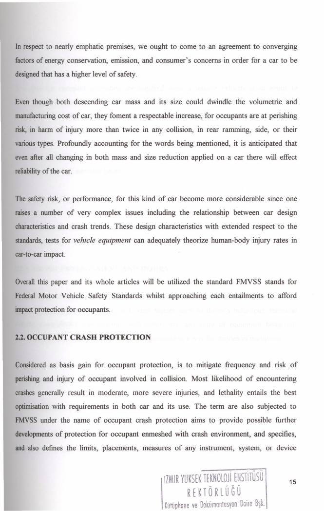
Considering average weight of the occupants (Figure 1.4.) in the number of four maximum
loaded vehicle weight is assumed to be reach to 1068kgs (700+328+40kgs)(distributed as 60%
in front, and 40%towards rear portion of the vehicle), including luggage loading.
Weight .
5th percen- tileadult
46.3 kg
95th percentileadult
97.5 kg.
Figure 1.4. Average weight of person considering height factor.
12
1.1.2.1.ECONOMIC PROVISIONS OF LOW MASS
Transportation now consumes more than %20 of the world's total energy. In next thirty
years, transportation will need 2-1/2 times more energy since the number of cars will
desperately soar from today's levels of four hundreds to the level one billion. If these trends
are projected to year 2100, cars will consume 40% of 10 times more energy (Sviden, Ove, 1992,
pp. ISBN 92-64-13752-1).
In the light of these data, term low-mass which is a centrepiece-part of the way in which
reducing consumption of traditional energy stocks is very tenable. Nowadays, almost all
engineering designers address those environmental concerns onto their project under the
nameas of environmentally friendly cars.
1.1.3. AN OVERVIEW OF FAMILY INCOME IN PARALLELING CAR
OWNERSHIP
Theexponential growth of car ownership and use relatively depends on economic well being
in developing countries. As income drives a higher level, the population life standards
relatively expand. Thus, purchasers individually purchase, maintain, and fuel the
transportation device. That also provides investments on transportation network entail
publicfunding in which transportation schedules and routes are tailored to public needs, as
wellas being inexpensive. By this individual needs car density per family is expected to reach
twicemore than it is.
13

CHAPTER 2
2.1. LIGHT CAR SAFETY IN PERSPECTIVE
Understanding reasons for dire injury conditions provide the requirements jointed as any
system,part, or component within car. These varies of requirements generally emerge as a
result of two important characteristics make drive fatalities of feather cars higher are
rollover propensity and compatibility. It is cited that, in jeopardy of fatal impact light
vehicles are twice as likely to have rolled over than other means. A rollover increases the
likelihood of occupant ejection, fatality or injury (An Overview of Vehicle Compatibility,
1998).
Other significant characteristic involves differences in car distinctions between means and
light cars, such as, weight, volume, or size, geometry, and stiffuess. According the test
results, gotten from FARS stands for Fatality Analysis Reporting System, crash statistics
demonstrate that, in side impacts, light cars are more injurious as a striking one than
passenger vehicles. For example, when LMV s (Low Mass Vehicles) ram on the left side,
especiallyto passenger cars, the risk of lethality to the car driver can be about thirtyfold
morethan the danger to the LMVs occupants (An Overview of Vehicle Compatibility, 1998).
This issue shows that during development period of such category, both technology and
materia! dimensions have been intensely focused on that vehicle group. Since utilizing
advancedtechnology light vehicles become superior to other categories of cars.
2.1.1. MASS AND SIZE ENFORCEMENTS ON A CAR
Changingcar's size and mass, one of the most considerable are orientated to the estimations
in proportion to the consumer's broad social concerns. Hereby, energy conservation and
emissionsacrifice, both in the name of environmental health, are not primary gains.
14
In respect to nearly emphatic premises, we ought to come to an agreement to converging
factors of energy conservation, emission, and consumer's concerns in order for a car to be
designedthat has a higher level of safety.
Even though both descending car mass and its size could dwindle the volumetric and
manufacturing cost of car, they foment a respectable increase, for occupants are at perishing
risk, in harm of injury more than twice in any collision, in rear ramming, side, or their
various types. Profoundly accounting for the words being mentioned, it is anticipated that
even after all changing in both mass and size reduction applied on a car there will effect
reliabilityof the car.
The safety risk, or performance, for this kind of car become more considerable since one
raises a number of very complex issues including the relationship between car design
characteristics and crash trends. These design characteristics with extended respect to the
standards, tests for vehicle equipment can adequately theorize human-body injury rates in
car-to-car impact.
Overall this paper and its whole articles will be utilized the standard FMVSS stands for
Federal Motor Vehicle Safety Standards whilst approaching each entailments to afford
impactprotection for occupants.
2.2. OCCUPANT CRASH PROTECTION
Considered as basis gain for occupant protection, is to mitigate frequency and risk of
perishing and injury of occupant involved in collision. Most likelihood of encountering
crashes generally result in moderate, more severe injuries, and lethality entails the best
optirnisationwith requirements in both car and its use. The term are also subjected to
FMVSS under the name of occupant crash protection aims to provide possible further
developmentsof protection for occupant enmeshed with crash environment, and specifies,
and also defines the limits, placements, measures of any instrument, system, or device
15

applied on car. Also, it is wishing that these all were capable of serving the needs and
producing centerpiece alternative through car designed.
The need for occupant protection are required when a relative velocity at or about 19
kilometres per hour with an unloaded car weight of 2,495 kilograms equals nearly 5450
pounds and at any speed up to 48kmph, or 30mph (Federal Motor Vehicle Safety Standards,
Standard No. 201,Occupant Protection in Interior Impact, 1998).
For more ability to understand, the term must be distributed in order for occupants to
encumber injury risk into two bases:
• Identifying the pre-crash conditions or addressing the crash environment, and
• Occupant protection with high determination in interior impact via an exterior offset
pulses through interior volume.
2.2.1. CRASH ENVIRONMENT AND INJURY
Crashes are likely to result in either environmental causes, for example road conditions,
inclement and degraded weather, and other factors such as driver's behaviour, technical
defects, compatibility and disparity with other cars, and roles of equipment being not
sufficientlyqualified. All of those factors predominate in a way for injuries of occupants.
Almost all crush trends by reason of causal factors from environment results in specific
locationdeformation on car body itself
2.2.2. DISTRIBUTION OF CRASH TYPES
Trajectoryof impact shall be either in a vertical plane parallel to car longitudinal axis or in a
planenormal to the surface at the point of contact. But, crash types or impact modes, to be
16
best simulated, are basically grouped by GAD stands for general area of damage and DOF
based on direction of force into frontal offset impact crashes, offset, or side offset impacts,
and rear impacts, and finally crashes as a result of rollover.
The categorization by object connected symbolize as OC is then divided into two types of
crashmodes as car to car and car to full barrier, or to fixed objects.
Frontal impacts are again branched into collinear and oblique (left or right) considering
DOF, and by general area of damage into offset (left or right). The same distributing is
availablefor other crash types just mentioned above (Stucki, Sheldon L. & Hollowell,
WilliamT., 1998).
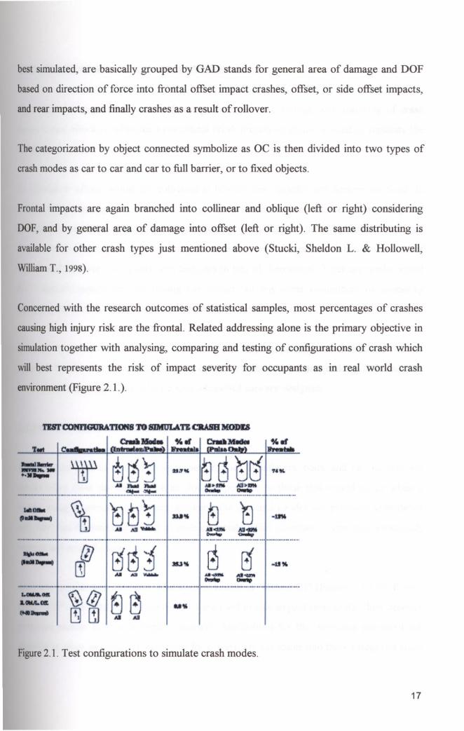
Concernedwith the research outcomes of statistical samples, most percentages of crashes
causinghigh injury risk are the frontal. Related addressing alone is the primary objective in
simulationtogether with analysing, comparing and testing of configurations of crash which
will best represents the risk of impact severity for occupants as in real world crash
environment(Figure 2.1.).
'I'IBI'cmmGUB4T1Of1S TO &:IMIJL4ft CRASH MODD
CndiI'Wel % fiI er..MIdM•• bnaII
~.:::- ~ ~ ~ SS++..- _ All·
...........-.._-- .__ .._-_ ......•- -_._~-~_.- -_..__ .. ._ _ _--_ ...~AI AlI-
:::::. {lJ E1. j' 3U~ B r5 -u~[1] AI Rl 'V_ ••••••• •••
.... . •.. - I .. ~ ......•.. ~ '" .
~@ as~t AI All
Figure2.1. Test configurations to simulate crash modes.
17
2.2.3. SIMULATION OF CRASH ENVIRONMENT
Simulation in conjunction with addressing, configuration, testing, and analysing of crash
environmentwhich is subjected to occupant crash protection could be used to replicate the
safetyperformance of cars currently in use.
In simulation of real world car collisions at laboratories, specific test devices are used. In
respectto nearly emphatic premises, first group of test instruments of use in comparing and
analysingto test data obtainable from performing of configurations. And, rests of them are
fixedand movable objects as full barrier, dummies and out-of occupant simulators instead of
driversand side-seat occupants, and test cars in lieu of themselves. Tests are implemented
for a specific equipment, for testing any system, or any other component or accessory
equippedcar so that whether they are successfully qualified or not.
Simulationsare also done by the reason of developing prototypes of crash avoidance
systems.As developing such systems in complete effectiveness and making their tasks in
immenseefficiency special hardware such as testbed cars are designed.
2.2.3.1.DUMMY RECOGNITION
Dummiesare used to test suppression device, such as inflators, belts, and i.e., so that test
resultsusing these devices will be as close as possible to those that would occur when a
humanbeing is present. In dummy grouping the age and gender are primarily considered
and,then test dummies described as male or female infant dummies, 3-year-old, 6-year-old,
teenageand adult dummies.
Anthropomorphictest manikins, also known mostly as "Hybrid m" (Figure 2.2.) for frontal
tests, "SID" and "BIOSID" (Figure 2.3.) are used in side impact tests under their product
prototypenames. Both side impact dummies' biofidelities for the responses measured are
superiorto other mannequins, especially for drivers, are extricable into three categories sized
18
by height are 5 percentile female, 50 percentile male, and 95 percentile male, respectively.
Hereby,the average heights for each category are:
• 5percentile population refers to ones less than 1640mm,
• 50 percentile refers height among 1640-1800mm,and
• 95 percentile equals to over 1800mm.
Shouldbe denoted that the use of combination of those dummies is higher in Family Car
otherthan cars.
As named above, although those two prototype dummies have their gradations to each
other,biofidelity of them according to test results to cadaver assessed to a parameter called
coefficientof variation as CVare analogous.
Dummypositioning differentiate according to testing purposes just the same as in a test in
whichthe test car is, assumed, to be struck on its left side, each dummy is configured and
instrumentedto strike its left side for analysing being measured acceleration data to body
parts from accelerometer mounted onto ribs, spine, femur and pelvis, or placed inside,
comingmind skull cavity, and any other certain part of body of the dummy, and thus for
specifyinginjury criteria and fatality risk.
19

Figure 2.2. Schematic of Hybrid III Test Dummy.
Figure 2.3. Schematic of Side Impact Test Dummy (BIOSID Dummy).
I'ZM'R YUKSEK TEKNOLOJi ENSllTOSO IREKTORLUGO ,
20

2.2.3.2. INJURY RISK BY SIMULATION
Simulationtogether with analysing, comparing and testing of configurations of crash shows
that injuries should be taken under three-risk-Ievel of injury as Moderate and More severe
Injuriesin symbol with MIS 2, serious and higher injuries in condense to MIS 3 as one-up
level,and the Fatal Injuries.
8.0%
6.0%
4.0%
2.0%
0.0%Full Barrier Left Oblique Right Oblique
Left Offset Right Offset
I_MIS 2 0 MIS 31
Figure2.4. Moderate and more severe injury risk to possible crash modes.
Asfiguredabove, for MIS 2 the injury risk is, somewhat, higher for most majority of cars in
crashesas identical as left offset in portion of about 7.6 percent than those described by full
barrierat a relative 6.8 %. And also for MIS 3, serious injury risk has the highest rate of 3.8
percentthrough full barrier crashes, and thereon above, left offset and right offset groupings
havelower serious injury rates of2.1 and 1.3,respectively.
Just another figure that explains impelled fatality risk for various crash modes by test
condition,are located to lower. Based on the figure fatality rates for left offset grouping (left
offsetand left oblique offset) result in higher fatality jeopardy at 0.43 percent than full barrier
whichis respectively about 0.25 percent. If all, given as figure 2.5., considered, the right
21

offset grouping (right offset and right oblique offset) are fourfold as likelihood of fatality
risk than left offset modes.
0,50%
0,40%
0,30%
0,20%
0,10%
0,00%Full Barrier Left Oblique Right Oblique
Left Offset Right Offset
Figure2.5. Fatality injury risk to possible crash modes.
2.2.3.3. BODY REGION INJURY ASSESSMENT
Inextricably above, injuries to specific body regions could also be separated into two-risk
levelof injury as Moderate and More severe Injuries in symbol with MIS 2, serious and
higherinjuries in condense to MIS 3.
Riskto a general body region group, that head, chest, or thorax or torso, arms, and legs are
branchof which, are figured as:
22
5.0%
4.0%
dP~ 3.0%01
ill~
2.0%:l
....•l:H
1.0%
0.0%
Arm
ThoraxHeadLegs
.Left Oblique-Left Offset OAll Frontals
Figure2.6. Risk to a general body region group (MIS 2).
1,2010
1,0%dP
0,8%~ •ill 0,6%~ :l..... 0,4%l: H
0,20/00,0%
Arm
ThoraxHeadLegs
.Left Oblique-Left Offset OAll Frontals
Figure2.7. Risk to a general body region group (MIS3).
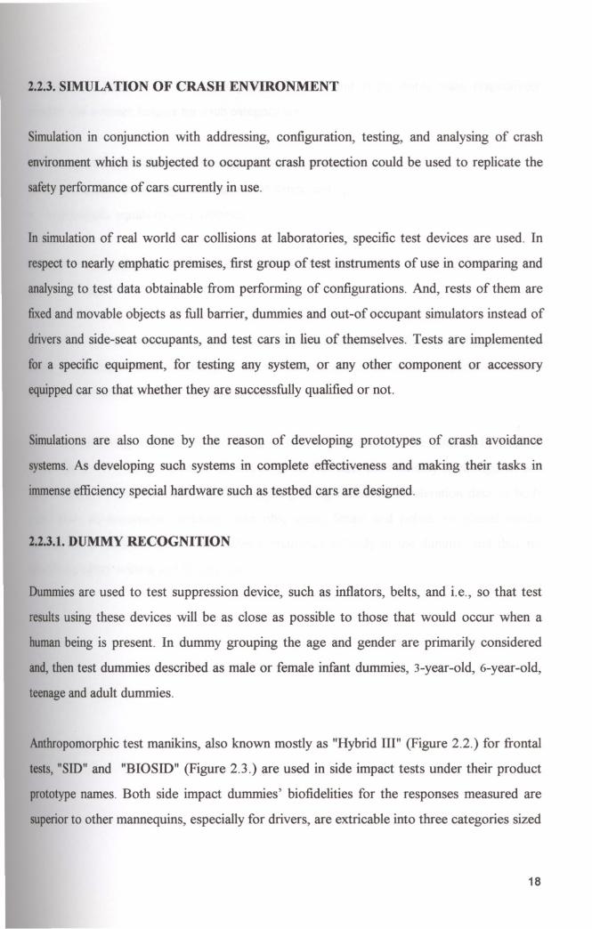
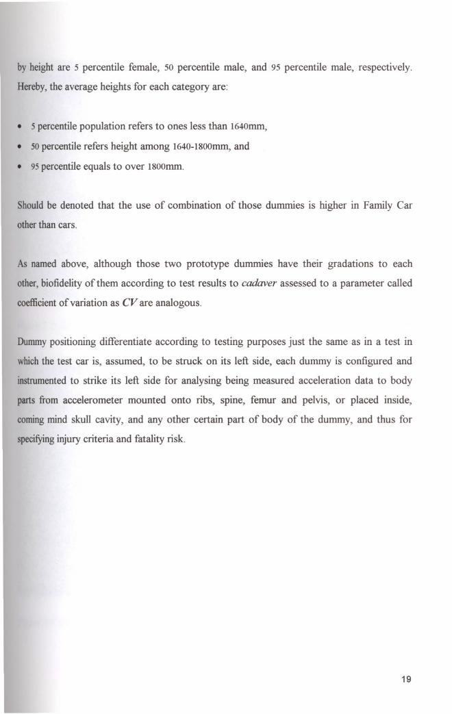
A comparisonof figure 2.6. and figure 2.7. shows that potential MIS 2 and MIS 3 injury
havea higher rates for legs in left frontal offset than all frontals with rested body regions
havingresemblances in both impact modes.
23
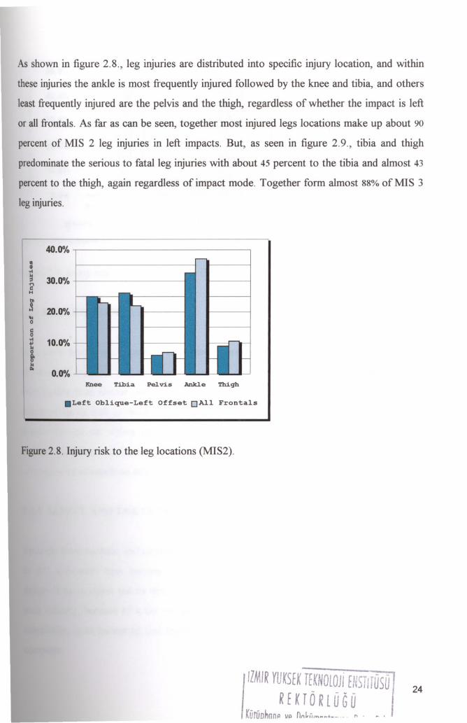
As shown in figure 2.8., leg injuries are distributed into specific injury location, and within
these injuries the ankle is most frequently injured followed by the knee and tibia, and others
least frequently injured are the pelvis and the thigh, regardless of whether the impact is left
or all frontals. As far as can be seen, together most injured legs locations make up about 90
percent of MIS 2 leg injuries in left impacts. But, as seen in figure 2.9., tibia and thigh
predominate the serious to fatal leg injuries with about 45 percent to the tibia and almost 43
percent to the thigh, again regardless of impact mode. Together form almost 88% of MIS 3
leg injuries.
40.0%
30.0%
20.0%
10.0%
0.0%Knee Tibia Pel.vis AnkJ.e Thigh
.Left Oblique-Left Offset DAll Frontals
Figure2.8. Injury risk to the leg locations (MIS2).
IIIMIR YUK5EK r~:KNOWJi ENSTIfUSO
REKTORlUGU
KOtiiDhnnp 1111 nfl~lij"'ftft' __"_ - " .
24

50.0%
40.0%
30.0%
20.0%
10.0%
0.0%Knee Tibia PeJ.tis AnkJ.e Thi.gh
.Left Oblique-Left Offset DAll Frontals
Figure2.9. Injury risk to the leg locations (MIS3).
2.2.3.4. RECOMMENDATIONS
In so many words, not regardless of plotted figures above with making the word stationary
as been said recently, that most percentages of crashes resulting in severity of injury and
even fatality from frontal cuttings through left frontal has the highest effect in local body
region of leg as well as thorax. So, to come to a conclusion, outcomes shows innovative
designsthrough car styling should be stepped up attempts to innovative article designing,
systems devising, equipment projecting, and so on, for helping to avend the dire
consequencesof accidents and alleviating them in frontal ramming.
2.2.4. SAFETY AND THE COMPUTER
Sincethe bare machine, and especially introducing the new atlas system as a part of product
in 1972, computers have become essential to society on applications on new fields as in
designof automobiles and its test processing. Moreover, in the period of being applied in
such industry, because of a car equipped with a variety of structural elements and their
complexity,exact measuring and implementing the process can be only hunched using the
computer.
25
The use of computer in automotive is two ways as either simulation or operating the
extended devices.
Thebasic hardware machine peripherals, as extended machine hardware, are complicated so
as to solve the functional requirements by developing any number of packages. The
automobile industry has a use for that application packages for simulating or circuit
analysing. Simulations of both design and test processing give such many opportunities to
designers and manufacturers. Time saving, solving exponential number of variables,
revealingcalculation, responsiveness are only some of them.
Those simulation packages are constructed with softwares consisting of predetermined
programmingcodes.
Advantageous of computer, curbing the extended input and output devices successfully
during testing, improves the production of a car prototype as lowest defect as possible.
Sincethe computer allows designer to minimize unreasonable allegations, the product as
wellas its testing results in best method a car to be newly minted up.
Especially,in simulations the car collision behaviour can easily be progressed. In doing so,
therecan remain a rested time enough to achieve substantial improvement for other areas on
carprototype.
Almostall simulations after innovating a device, or any system are attempted to measure its
safety adequacy. Both simulation and performing the extended devices in planned
configuration, the foremost portion of testing is aside body and restraint elements.
Deformationtables, inertia loading on equipments, yawing moment or torque on body,
aerodynamicstability with drag reducing and for other all a computer counteracts the
unforeseeablecorrupts.
26

For example, in any impact test, side or frontal, or rear, and has only time approximately 70
milliseconds for collide duration, just for the interrupting and capturing the wishing section
at any certain graphic, and at a particular juncture, CAD systems (or CAS) are essentially
used. Here, a configuration of computer-based measuring gives the advantageous of
repeatability, simultaneously analysing, comparing, determining the factors of deformation
ratio after first contact, and testing the stiffuess of doors and door hinges for all longitudinal,
transverse, and inertia load continuously at any level giving the proxy. Geometry, chassis,
finiteelement thickness, yield strength, modulus of elasticity are set as input data or data
sets.As a secondary way of using the computer in that measuring, capturing provides by an
externaldevices as cameras, the rest of the job, completed by extended bare machine after
batchingthe data sets into the computer. The tests for the deformation zone of the car on
leftside are significantly carried out.
Apartfrom those, dummy injury testing encompasses a wide range of computer use. For its
simulation,biofidelity entailments and physical algebraic equations such as, mass, inertia
moment and body temperature, are set in the program. The usefulness hinges on the
parameters to be more encompassing and more detailed. In reality, whilst the car being
decelerated, however, the occupant's jerking gathers speed. From that point of view,
dummyinjury testing for encumbered the lurching criteria could be separated the receding
behaviourof the car. Then, the needy estimations calculated and the results combine with
the each other. Restraints systems using so as to harmonize the occupant to the car slowing
downalso have the opportunity of testing in simulations.
Verycomplicated simulations are integrated with the mechanical devices. Simulator room is
an essentialmember of such systems. Those constructed on a base with the ability to move
in six axes and regarded as moving base simulator with the ability to represent antecedent
events. It is used higWy intensely in car road test simulation. Since the mechanical
movement,the drivers provided to feel themselves as if they were in real world.
27
2.2.5. TESTS
Car tests at laboratories implemented in an isolated room, or in such areas for road test.
Aftera test was done, the special working out disquisitions are ordered. Those orders don't
obligeto, but for the certainty of the car reliability indubitably should be taken with all due
care.
Majorityof the test applied for a specified object, and the reliability of its results, others as
verbose should be removed from the whole in case of affecting the load upon or the
deflectionof the car. Needless to say, negligible parts could be not.
Here,with all given knowledge, focal points of the test will contain:
Outer parts:
• Chassis,on lateral, frontal, and rear ramming,
• Doors, on lateral impact,
• A number of articles including hinge, latch, and windshield and windshield mounting,
and
• Uppermostportion of the body, in the event of rollover.
And inner parts:
• Seatsas outboard component and seats' anchorages.
28
a. Outer parts
a.I. Chassis
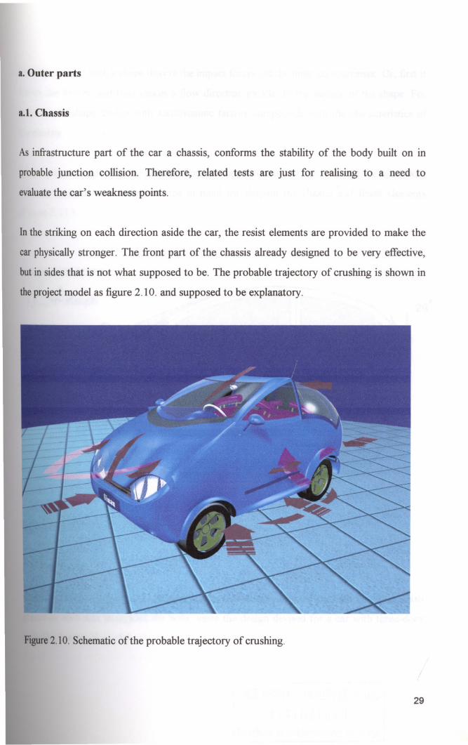
As infrastructure part of the car a chassis, conforms the stability of the body built on in
probable junction collision. Therefore, related tests are just for realising to a need to
evaluatethe car's weakness points.
In the striking on each direction aside the car, the resist elements are provided to make the
car physically stronger. The front part of the chassis already designed to be very effective,
but in sides that is not what supposed to be. The probable trajectory of crushing is shown in
the project model as figure 2.10. and supposed to be explanatory.
Figure2.10. Schematic of the probable trajectory of crushing.
29
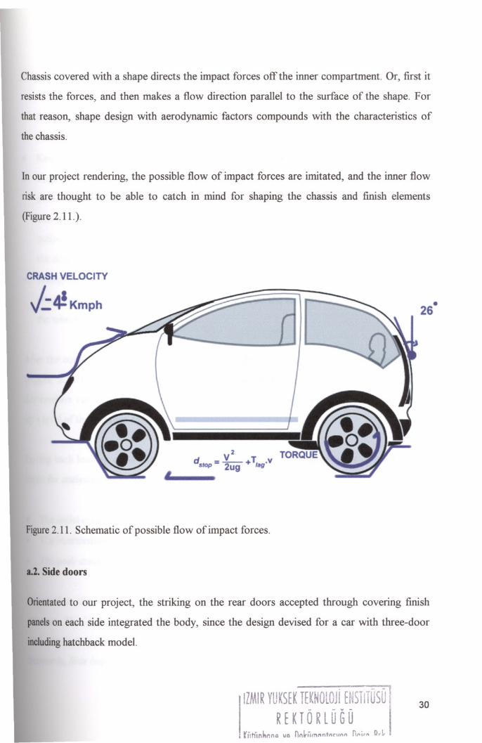
Chassis covered with a shape directs the impact forces off the inner compartment. Or, first it
resists the forces, and then makes a flow direction parallel to the surface of the shape. For
that reason, shape design with aerodynamic factors compounds with the characteristics of
the chassis.
In our project rendering, the possible flow of impact forces are imitated, and the inner flow
risk are thought to be able to catch in mind for shaping the chassis and finish elements
(Figure2.11.).
CRASH VELOCITY
J::.4!KmPh
v2d ---- +T vSlOp - 2ug lag"
Figure2.11. Schematic of possible flow of impact forces.
a.2. Side doors
•26
Orientatedto our project, the striking on the rear doors accepted through covering finish
panelson each side integrated the body, since the design devised for a car with three-door
includinghatchback model.
IZMIR YUKSfK TEKNOLOJi HlSTlTUSO 1
RfKTORlUGU
30
Presets of the test in side collide, the procedures:
• Removing the seats,
• Placing the side windows in uppermost position,
• Keeping the door locked,
• Preparing and positioning the loading device, which is a rigid steel cylinder or
semicylinder of 304.8mrn diameter with an edge radius of 13 millimeters, its longitudinal
axis as in parallel to car's vertical direction, and that direction laterally opposite to the
midpoint of the junction line 127millimeters above the outermost of the lowest point of
the door, regardless of the any protective moulding as side fenders, and
• Fixing the car rigidly vertical to its transverse line or horizontal centerline by means of
attachments between the wheel base line located on the forward and rearward portion of
the wheel centerline.
Afterthe conditions achieved (Figure 2.12.), simultaneously the configuration implemented
(Figure 2.13.). So, using the positioned loading device a force-laden door takes the
defonnationversus as of 120seconds of points in time until the device continuously reaches
upa levelof the distance 457.2mrn.
Duringeach loading of 55 kilograms per inch in specified time, three types of level are the
timesfor analysing the deformation zone of the doors. These:
• Theinitialcrash loading duration,
• Theintermediate crash loading duration, and
• Thepeak crash loading duration.
Forthe first, the initial crash load is the average force deforms the doors over a third of the
457.2rnm.The latter is required to deflect the doors in initial 304.8 millimeter of the crush.
And,the last applied to those over entire level of 457.2 (Federal Motor Vehicle Safety
Standards,Side Impact Protection, 1998).
31

Wheelbase (W)
3711 O.5W
"-------
-I
Directionof Travel@ 33.5
mph
Vehide B
Figure2.12. Test configuration of vehicle for side impact.
32

CENTERLINE OF VEHICLE
PLAN VIEW
II'--+--\.!./
I
T DIRECTIO~OF LOAD_I
12 INCH DIAM.
MID POINT OF HORIZONTAL LINE
HORIZONTAL LINE
5 INCHES ABOVE THELOWEST POINT OFTHE DOOR
YzIN. R.
LOADINGDEVICE
STRUCTURES ABOVE THEBOTTOM EDGE OF THE DOORWINDOW OPENING
BOTTOM EDGEOF DOOR WINDOW
OPENING
LOWEST POINT OF THE DOOR
Figure2.13. Loading device positioning and its application towards the doors.
In project, the doors since their importance of usability, such as easy opening-easy entry
evenby a child, at the off-peak times simply to egress the compartment, it has the properties
of light,enough door- opening. The concept of being small in size also allowed to directly
reducethe four-door concept to the use of two-door one. Especially, light-door enable both
driverand occupants to better evaluate obstacles on off-road travelling.
Thetwo-door is directly effected use of interior space. For instance, the seats are designed
to allowthe occupant to seat the rear within the function of folding and when required
simplyslidingforward.
33
a.3. Door latches and hinges
Any door is in need of the latch and hinge to engage and to lead to the occupant
compartment. A hinge allows the door to have a door-opening area in the position of more
than 50 percent of its opening to the point on the vertical and rearward of the seat on each
side.Evidently, the hinge is a joint element fixed on one side to the car frame, on the other
mountedonto edge-side of the door, consisting of either metal or plastic provides the door
to rotate its surround freely. A latch is the mechanism that locks the door automatically after
striking.
Componentsof doors are tested under the conditions by putting a charge of dynamics and
inertiaload. Loading aims to measure the resist levels of those.
Loadingson sides of longitudinal and transverse to the hinge applied at an amount of force
between 1135 kilograms and 980 kilograms. The physical characteristic of the hinge is
assumedto be not separable under those loadings. It is very important such that many of
perishinghave ensued after the doors had been separated and moved off from the body,
especiallyin rollover crashes.
Forthe case of splitting, the role of latch is higher than supposed to. It helps by disengaging
fromthe locked position due to its malfunction leading to design defects. For that reason,
thesametest are done for that component. In test, locking being functioned as in real world
(suchthat open-close process is progressed in the number of twenty thousand times).
Inertiais a tendency of the latch and the hinges being in a position still. The inertia loads of
bothare implemented separately from the dynamic load. In tests, a car shall not free from its
completelylatched position under a particular loading of 30 grams (Federal Motor Vehicle
SafetyStandards,Door Locks and Door Retention Components, 1998).
34
a.S. Windshield and windshield mounting
Inefficient the restraint systems are the case for jolting through outer surface in a sudden
brake or colliding. A windshield in its pre-modem models had been designated as a heeding
elementfor airflow, onward steering controller. But, within many circumstances keeping its
basic function, it is improved entirely in an abyss field. It is the field that aims to achieve
protection for outing outward.
Thatis not the indictment of ejecting of the force-laden occupants toward innermost surface
of the windshield in lieu of causing serious head injuries and being sheared by glass. To
remedycases, windshields are provided with a glazing material that additionally helps for
spreadingthe forces more equally all around the windshield causing, thence the merest effect
andbeing unscathed in case of splitting glass material.
Fortesting the improvements on windshield the following steps preset:
• Positioning the 50 percentile dummies at each front outboard designated seating
locations,
• Specifying the protection zone area by affixing template onto windshield for both
controller and occupant (Figure 2.14.),
• Loading the car in addition to its unloaded car weight up to an amount of 136kgs,
• Fillingthe canister with a solvent, less than up to the brim, between levels from 90 to 95
percent of its full capacity,
• Inflatingtires and setting other even negligible parts.
Implementingthe test, at a fixed speed relative to the 48k:mph, accounts for and, therefore,
entailsthe following optirnisation on windshield:
• If the occupant with its belted seating position, the windshield supports preventing
intrusionoutward at least 50 percent of its periphery or mounting,
35

• Ifnot, and the belt inefficient, should be protecting at the level three-fourth, and
• Both takes the width of at least 6 mm.
For any intrusion the mounting elements are of lead in importance. For stabling the
mountingsthe fixing is considered to be not detachable around the temperatures between -9
and 43 degrees Celsius (Federal Motor Vehicle Safety Standards, Windshield Zone
Intrusion, 1998).
76.
HORIZONTAL EXTENSION
BEYOND OUTERMOST CROSS SECTION OFCONTACTABLE POINT PROTECTION ZONE IN
TYPICAL VERTICALLONGITUDINAL PLANE
45'/
LOWER BOUNDARY OFWINDSHIELD PROTECTEDZONE
POINT OF CONTACT BETWEENSPHERE AND INNER SURFACEOF WINDSHIELD
FRONT VIEW SIDE VIEW
Figure2.14. Windshield protection zone (All dimensions in mm).
Inthe project, windshield is glazed with the types of glass-plastic. It contains of from outer
to inner, tempered glass, polyurethane film with energy absorbing capabilities and
polyurethanefilm with abrasion resistance capabilities (Duffy, 1996). It reflects the
aestheticalportion of the design. Forming it with body, in open-body cars, or on fully closed
typeswith other windowpanes identify the shapes. Also, it provides to see the around and
deflectsthe airflow to the side of the driver. Seeing around clearly is required the
36
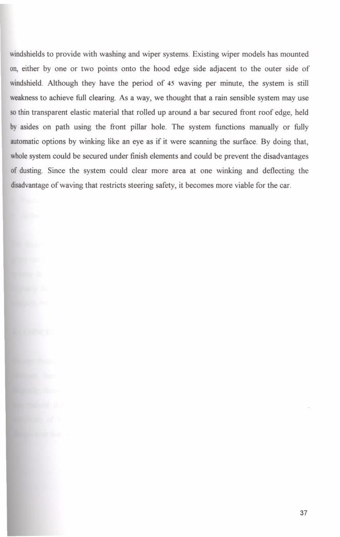
windshields to provide with washing and wiper systems. Existing wiper models has mounted
on, either by one or two points onto the hood edge side adjacent to the outer side of
windshield. Although they have the period of 45 waving per minute, the system is still
weakness to achieve full clearing. As a way, we thought that a rain sensible system may use
so thin transparent elastic material that rolled up around a bar secured front roof edge, held
by asides on path using the front pillar hole. The system functions manually or fully
automatic options by winking like an eye as if it were scanning the surface. By doing that,
wholesystem could be secured under finish elements and could be prevent the disadvantages
of dusting. Since the system could clear more area at one winking and deflecting the
disadvantageof waving that restricts steering safety, it becomes more viable for the car.
37

CHAPTER 3 SAFETY SYSTEMS
Anysystem that aids in hindering accidents and uses its ability to lessen or to moderate risky
resultsfrom ram injurious, albeit at a mortal crash. According the search on crush rates per
countryTurkey has a population of 70% that had an experience with traffic related accidents
at least one time in their lifetime while the other countries at an average of 50%. That also
showshow utmost importance a restraint system for occupant, especially for our country.
Veryinnovative systems emerged as safe can primarily be distributed into two groups:
• PassiveProtection Systems and,
• ActiveProtection Systems.
The discriminations of two to notice are rather more complex such that one member of
groupcan become a member of another group or, can be designed as semi-active or passive
systemsin proportion to using of electronic components. Therefore hardware which is
originallyfirst founded and settled in which category, will be started explaining in that
category,with respect to its other characteristics being assumed a part of it in that portion.
3.1. CONCEPT OF PASSIVE PROTECTION
ConceptPassive Safety contains both structural and design features that require no action by
occupant.Such systems could be put to use as in a wide spectrum of car structure.
Originally,those systems forlornly designed to provide specific purposes. But, by the years it
was realized that centerpiece arrangements of passive protection systems, although in
complexityof both engineering and design, were multi connected or integrated system
designssuchthat whole parts would work in a way in which the harmony reached up.
,ZMIR YUKSEK TEKNOLOJi ENSTITOSO
RfKTORlUGO
'" •..c,_~~.,,, VP nnk[jrnnnto~vn!1 O:tim Ih~
38

3.1.1. RESTRAINT SYSTEMS
Most likelihood of knowing as passive protection systems, are occupant restraint systems
emerge as passive belts, knee bolsters, and head restraints with seats. The purpose of these
equipments is to protect someone in case of ejecting through the interior surface. Such as
through the windshield, instrument panel, pillars, or side window pans and doors of the car
andto encumber their jerks to such deceleration levels as can be endured without externally
andinternally serious to fatal injurious.
a. Passive Belts
Primitivetype of Passive Belts is knowing as sash belt now superfluous that was jettisoned
as of 1960. As for first concepts of main passive belt were developed through the '70s and
early '80s and cars outfitted with various types of passive belts around '835 by stationary
regulations in relation to the requirement of passivity in car occupant protection systems.
Withadoption of passive belts and within its starting using in cars showed that the injury risk
for occupants, first, significantly mitigated, even though those had produced unreasonable
andunnecessary injury patterns.
Passivebelt has three types of its configuration as:
• two-point shoulder belt, or torso belt,
• two-point and door-mounted belt, and
• three-point and door-mounted belt.
Firstproduced model of passive belts two-point shoulder belt attached to a retractor at the
consoleand contains a mouse as motorized buckle running along the roof rail. As front door
opens, simultaneously the belt makes its forward movements to allow the occupant to
ingressor to egress the car. When the doors close the belt goes back rearward to the
windowframe or pillar. But, although reducing the injury risk the belt foments essentially
importantthree types of injury patterns due to the allegations in its design. These are:
39

• The risk of ejection, as well it might be ended with death,
• The risk of submarining emerged in frontal collisions as the lower portion of occupant's
body forward and outward under the belt, results in spinal cord injury and even
decapitation as a result of occupant to be restraint by his or her neck. To encumber
abysmallyhigh risk of injury and moderate an additional passive system concepts as knee
bolster, and lap belts were introduced with this belt so as to allow femur bones to handle
the occupant loading in a frontal collision and to provide the same pelvic restraint, and
• The risk of thoracic injuries, rupturing aortas, and lacerated livers as the forces applied
from the belts to the torso.
The second model two-point and door-mounted belt assembly to the front doors by a
permanentlymounted shoulder belt, or torso belt. Once the door opens the belt recedes
awayfrom the occupant for making riding on and riding of position available. That systems
is in need to be provided by knee bolster instead since the same injury patterns incur as in
two-point shoulder belt, or torso belt, but additionally the occupant might be totally
unprotectedin event of opening doors.
Thethird and last is a combination of the door-mounted belt as well as two-point with a
integratedlap belt, together all mounted and anchored in the door. The belt contains a
bucklein order for occupants to use it as either a passive or manual use. Such that when the
latchis disconnected and the door is its fully opened position the belt easily can hang on the
car's door and once the door in its fully closed position the occupant can buckle the belt as
ina manualuse. The only risk of the belt is to leave occupants in their unprotected and fully
unrestraintpositions in case of door latch disengaging from locked position (palmer, Robert
M.N., Passive Belt Litigation).
Thosesigned product risks for belts break even the protection as a result, and all become
insufficientto provide the occupant not to exceed the impact protection zone. But, should
thinkthat any car with any belt correctly placed in exercise of due care is counted as one and
a halfcars. Otherwise, a belt halves the unladen car weight. So if all considered, it is very
40
simpleto correct that application defect. Missed anchoring system is there in synovial pillar,
or B pillar, a very structural stiff area, next to the front door window frame where the door
is formfitted to, just in stead of in the door. In doing so, the effectiveness is tied. But the
easyway of getting out will be lost.
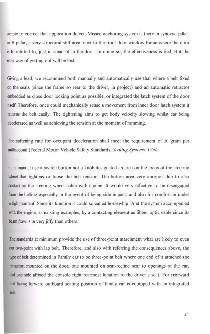
Givinga lead, we recommend both manually and automatically use that where a belt fixed
on the seats (since the frame so rear to the driver, in project) and an automatic retractor
embeddedas close door locking point as possible, or integrated the latch system of the door
itself Therefore, once could mechanically sense a movement from inner door latch system it
tautens the belt easily. The tightening aims to get body velocity slowing whilst car being
deceleratedas well as achieving the tension at the moment of ramming.
The softening rate for occupant deceleration shall meet the requirement of 20 gram per
millisecond(Federal Motor Vehicle Safety Standards, Seating Systems, 1998).
Inits manual use a switch button not a knob designated an area on the locus of the steering
wheelthat tightens or loose the belt tension. The button area very apropos due to also
contactingthe steering wheel cable with engine. It would very effective to be disengaged
fromthe belting especially in the event of being side impact, and also for comfort in under
weighmoment. Since its function it could so called horsewhip. And the system accompanied
withthe engine, as existing examples, by a contacting element as fibber optic cable since its
beamflow is in very jiffy than others.
Thestandards at minimum provide the use of three-point attachment what are likely to even
outtwo-point with lap belt. Therefore, and also with referring the consequences above, the
typeof belt determined in Family car to be three-point belt where one end of it attached the
retractor,mounted on the door, one mounted on seat-recline near to openings of the car,
andone side affixed the console right rearmost location to the driver's seat. For rearward
andfacingforward outboard seating position of family car is equipped with an integrated
belt.
41
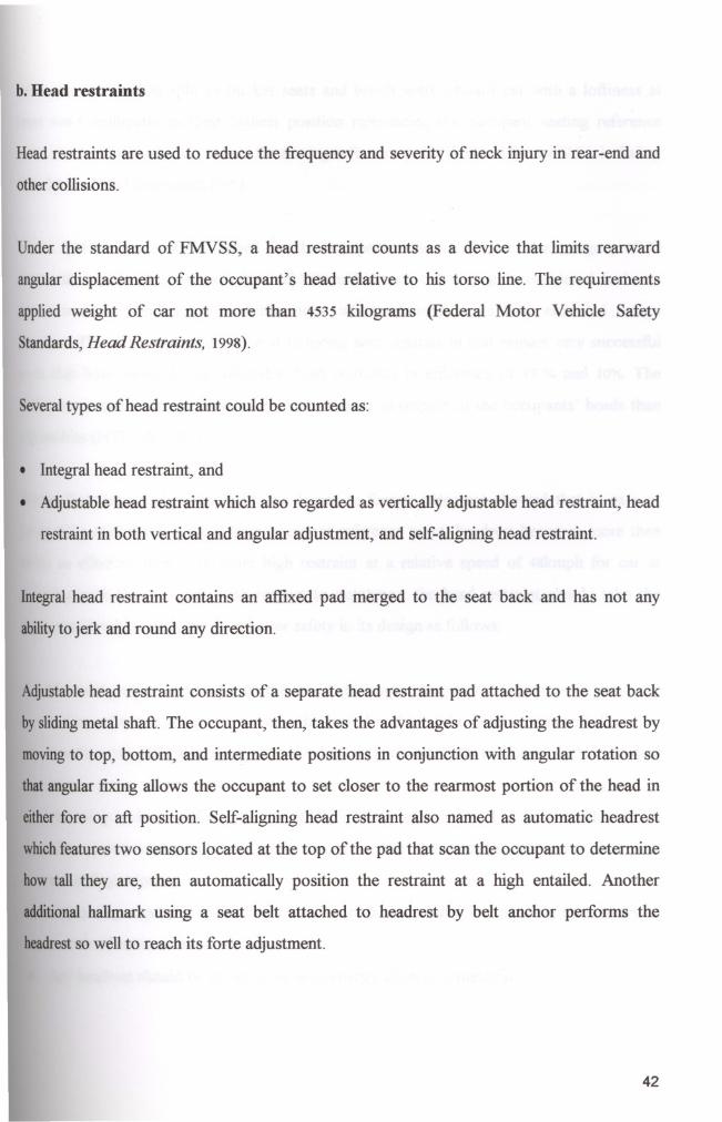
b. Head restraints
Headrestraints are used to reduce the frequency and severity of neck injury in rear-end and
othercollisions.
Under the standard of FMVSS, a head restraint counts as a device that limits rearward
angular displacement of the occupant's head relative to his torso line. The requirements
applied weight of car not more than 4535 kilograms (Federal Motor Vehicle Safety
Standards,Head Restraints, 1998).
Severaltypes of head restraint could be counted as:
• Integral head restraint, and
• Adjustable head restraint which also regarded as vertically adjustable head restraint, head
restraint in both vertical and angular adjustment, and self-aligning head restraint.
Integralhead restraint contains an affixed pad merged to the seat back and has not any
abilityto jerk and round any direction.
Adjustablehead restraint consists of a separate head restraint pad attached to the seat back
by slidingmetal shaft. The occupant, then, takes the advantages of adjusting the headrest by
movingto top, bottom, and intermediate positions in conjunction with angular rotation so
thatangular fixing allows the occupant to set closer to the rearmost portion of the head in
eitherfore or aft position. Self-aligning head restraint also named as automatic headrest
whichfeatures two sensors located at the top of the pad that scan the occupant to determine
how tall they are, then automatically position the restraint at a high entailed. Another
additionalhallmark using a seat belt attached to headrest by belt anchor pertorms the
headrestso well to reach its forte adjustment.
42

Both are installed on split or bucket seats and bench seats inboard car with a loftiness at
least 698.5 millimeter in their highest position referencing the occupant seating reference
point or H-point, or SgRP, stands for seating reference point (Federal Motor Vehicle Safety
Standards, Head Restraints, 1998).
Those systems are designed based for the occupants who involved in the category of 95
percentile equals an average height of 1800 millimeters or over and considered to be in
7l1.2mm above the seating reference point when adjusted to its fully extended design
position. The effectiveness of those at reducing neck injuries in rear impact very successful
such that both integral and adjustable head restraints in efficiency of 17 % and 10%. The
differenceis due to integrals primarily being higher in respect to the occupants' heads than
adjustables(NTHSA, 1982).
Withintheir historical background, the forces to forage outcomes showed that in case of
being787.4millimeter shallow from occupant reference point, headrest becomes more than
twice as effective than a 7l1.2mm high restraint at a relative speed of 48kmph for car at
reducingneck injury. Again with respect to outcomes, the head restraint should take the
mostconsiderable attributes for a better safety in its design as follows:
• Measuring either 63.5mmbelow the top of the head restraint or 635millimeters above the
seating reference point or H-point, the lateral width of the head restraint shall not be
less than 254 millimeters for use with bench-type seats and 171.45mm with individual
seats,
• Increasing recliner stiflhess results in diminishing neck injury, but on the other hand,
using plastic materials to a great extend in the seat recliner saves for occupant
rebounding velocity,
• Contouring edges not more than 3.2 mm in radius precludes any possible neck injury as
a result of static contact by a head, and
• Anyheadrest should be constructed with energy-absorbing material.
43
C. Seats
Seats placed either front or rear seating position, used as an outboard-seating element. Seat
types in the car are bench and bucket with the options of adjustment, folding, and armrest
for the front and back positioning. Seats are the snug elements and it is also the equipment
for decreasing the forward sliding in any braking, and a device absorbing the rearward
collideloading. Since their functions, a seat design required much attainment.
Design features of the seat, in the event of rear ramming, are considered to meet the
followingneediness:
• Stiffness,
• Containment and retention,
• Preventing whiplash, and
• Diminishing rebound velocity.
Therecliner stiffness mitigates the neck injury or whiplash injury as well as a head restraint.
Theother factor of rebound velocity is met by using the plastic of energy absorbing material
in the seat recliner. Rebound velocity also lessened over the surface of seat itself, and
supportedby means of bumpy texture with poring.
The construction of stiffness takes the trajectory of force as base. For an installation of
benchseat in the rear, in a seat plane versus the vertical torso line, a stiff strut, as rigid cross
memberof the carcass in the horizontal plane of the seat's center of gravity, is placed in
frontof the seatback frame for forward loading. Just for rearward loading, a new one faced
anotheralready existed. Next, a diagonal member affixed on each side of the carcass from
the horizontal centerline on the seating bar adjacent to the struts in the centre of the gravity
to a point forward end of the seating anchorages. And then, the carcass with members fixed
onthe car chassis (Figure 3.1., Figure 3.2., Figure 3.3.).
44

J/
HORIZONTAL REARWARD
fORCE THROUGH THE
CENTER Of GRAVITY
DIAGONAL'nUT """OtED
Figure3.1. Constructing elements by direction of impact.
Theinstallation of the bucket or individual split seats for the front outboard seating position
requiredtwo rigid supports as one base to the chassis the other interval element among base
andseat frame. An additional design hallmark as suspension is combined with the seating
carcass.
45
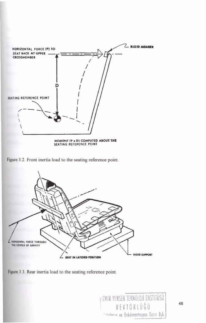
RIGIDMfMIIl
D
HORIZONTAL FORCE (P) TO ~SEAT BACK AT UPPER __ -=-"'=--_-=-""':--_-_-_--_- .CROSSMEM8E1t '/
//III
I
,-- I-.....
.....•...
SEATlNG REFERENCE POINT
(--~\
\
MOIoAENT tP x DI COIoAPUTED AaOUT THESEATING REfERENCE POINT
Figure3.2. Front inertia load to the seating reference point.
RIGID SImOlT
Figure3.3. Rear inertia load to the seating reference point.
IlMIR YUKStK TfKNOLOJi rNSTlTUSO
RtKTORlUGU
,- >i'r.I.,I1:'11 ve Dokumantasyon DilifU B~k.~_.•....•..•._,.-- ...• """" ..._--
46

Here, for no sliding, a material, as gorix, can be used, which also immunises the film heat
level and never change its temperature, and contributes the occupant by no absorbing the
heat coming body so as to reduce the perspiring, and oppositely to increase the snug. The
inner element underneath the cover need be selected from the energy absorbing material. As
can be seen, the features have a number of convergences with the headrests since their
common sharing.
The options for adjustment, folding, and foldable armrests with the seat presents some
designproperties on body and for a roomy position. Adjustment achieved by an adjuster as a
part of the seat makes forward and versus positioning as well as rotating. The portion of
foldingin the family car used as a design hallmark for emergence a three-door model. And
the placements of armrests are lashed onto the side doors, and the rearmost covered
compartment panels with having no door-openings. That rest has a secured rigid member
laterally32mm inside the cover surface of the panel with a height of more than 25mm.
In respect to childrests as mini seats or restings, their design can be either factory installed
builtin childrests with rear facing system or add-on child restraint systems.
Factory installed rests is a built in systems and installed the rearward outboard seating
positionpermanently by seat orientation reference line, as for latter type is in a use with an
attachableoption. Both systems keep the infant in position entirely opposite to the moving
offdirection in order to keep the child smashing the surfaces in compartment impact zone.
Theentailments for child restraint device are thought together with airbag as:
• If a child restraint system is equipped with a device that deactivates the passenger-side
air bag in a car when and only when the child restraint is installed in the car and gains a
signal,for at least 10 seconds after deactivation, and
• The child restraint system should be installed in the right front seating position with a
continuous-loop lap shoulder belt.
47

In project seats designed rotatable from one point that together anchoring point is the same
location with the belt anchor location. It is considered only for aesthetic proportions. By
doingthat, one biggest point on each seatback aesthetically is emphasized. And condensing
adjustable restraint system together with seatbelt provides functioning together in the event
of colliding (Figure 3.4.).
fa
Figure3.4. Schematics of seats of Dainty Vehicle.
48
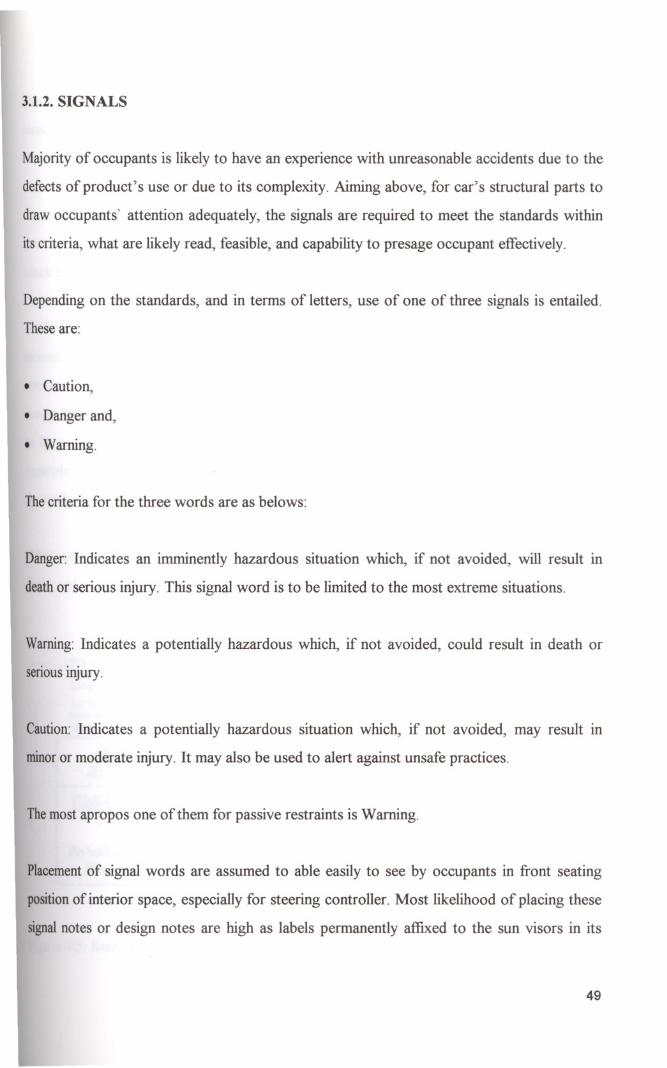
3.1.2. SIGNALS
Majority of occupants is likely to have an experience with unreasonable accidents due to the
defects of product's use or due to its complexity. Aiming above, for car's structural parts to
draw occupants' attention adequately, the signals are required to meet the standards within
itscriteria, what are likely read, feasible, and capability to presage occupant effectively.
Depending on the standards, and in terms of letters, use of one of three signals is entailed.
Theseare:
• Caution,
• Danger and,
• Warning.
Thecriteria for the three words are as belows:
Danger: Indicates an imminently hazardous situation which, if not avoided, will result in
deathor serious injury. This signal word is to be limited to the most extreme situations.
Warning:Indicates a potentially hazardous which, if not avoided, could result in death or
senouslDJUry.
Caution:Indicates a potentially hazardous situation which, if not avoided, may result in
minoror moderate injury. It may also be used to alert against unsafe practices.
Themost apropos one of them for passive restraints is Warning.
Placementof signal words are assumed to able easily to see by occupants in front seating
positionof interior space, especially for steering controller. Most likelihood of placing these
signalnotes or design notes are high as labels permanently affixed to the sun visors in its
49
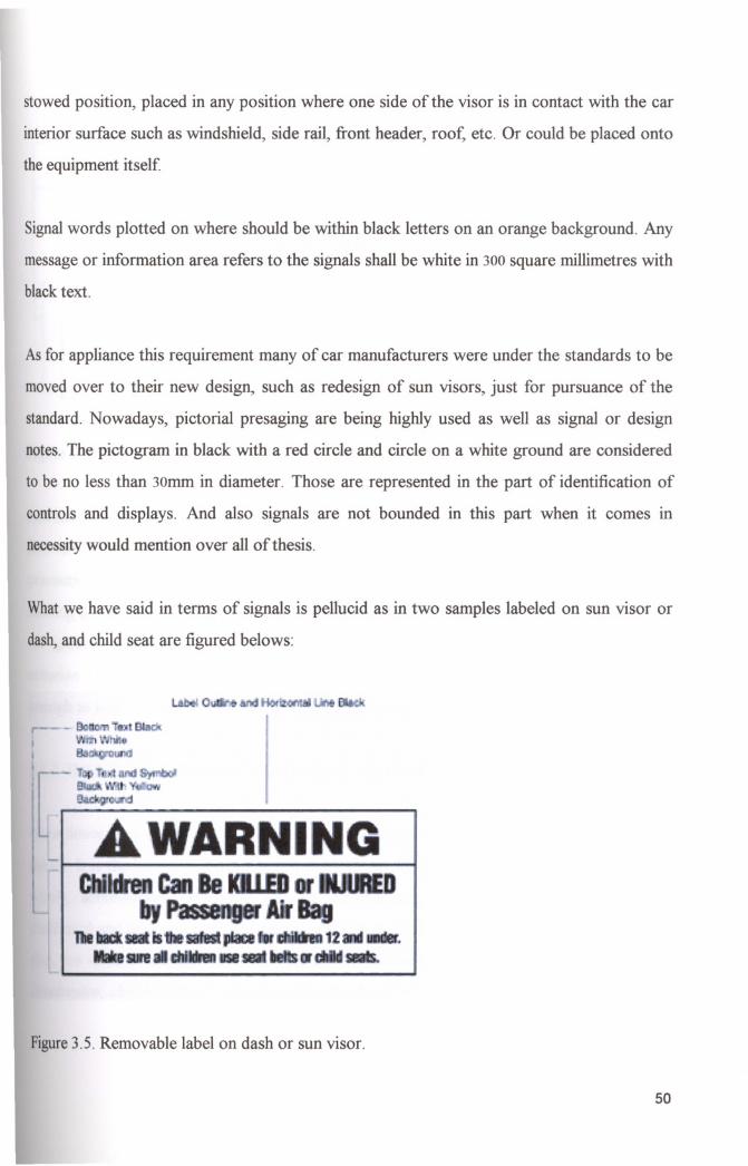
stowed position, placed in any position where one side of the visor is in contact with the car
interior surface such as windshield, side rail, front header, roof, etc. Or could be placed onto
the equipment itself
Signalwords plotted on where should be within black letters on an orange background. Any
message or information area refers to the signals shall be white in 300square millimetres with
blacktext.
Asfor appliance this requirement many of car manufacturers were under the standards to be
moved over to their new design, such as redesign of sun visors, just for pursuance of the
standard. Nowadays, pictorial presaging are being highly used as well as signal or design
notes. The pictogram in black with a red circle and circle on a white ground are considered
to be no less than 30mm in diameter. Those are represented in the part of identification of
controls and displays. And also signals are not bounded in this part when it comes m
necessitywould mention over all of thesis.
Whatwe have said in terms of signals is pellucid as in two samples labeled on sun visor or
dash,and child seat are figured belows:
Figure3.5. Removable label on dash or sun visor.
50

'J
Figure3.6. Label on child seat where child's head rests.
Justanother signal is sounded as lights and buzzers or chimes. These audible signals are very
innovative electronic systems connected to the passive restraints by a cable within a
precautionary warning interlude between 8 to 12 seconds that activates a continuous or
flashingpresaging light alteringly with a period of time of 60 seconds, beginning when the
car ignition switch is moved to on or in engine cranking position. The most considerable
criterionfor them are, sequencely, to be enlargedly enough to presage and lenghtenedly
enoughto hear.
3.1.3.IDENTIFICATION OF CONTROLS AND DISPLAYS
Oncedriver gets on a car the communication between each other provided by existing of
means.It is the harmony, one of which supports auxiliary control and display means are by
words, abbreviations, symbols, and by illuminations, whether they are mounted on
dashboardand on any certain location around head form that those all facilitate selection of
that, are utmost seriousness to the steering controller's attention. Or the others, such as
accelerator, clutch, around seating position need not be identified.
51

Defined words or abbreviations, and illustrations of the means are presented in figure 3.7.
and figure 3.8. would be helpfully useful for corning explainings:
COlumn' Column 2Column 3Column 4
Hand Operated COfItrois
IdenHlying Wordsldenti/ylfl{;Illuminationor Abbrevfaffon Symbol
••••s•••.lJit"ng Swlch
Ugh".'(J-5---,..Heacf~ andTaillamps
IManulacl •••• Qotionl2(Manutac::urer OpIion)2---
Horn
HofO~4---Turn SOU'"
¢¢3--- S---Haza,d Warnmg
HCllard~sV••
Signal
W_W;ping
Wlpero-WlpB\.\7V••System
WtndshieldWa.shing
Washer or Wash
~V••
S,..mI
Windshield Washing
Wash·W,,"
~V••
and Wiping Coni>InedOf Washet·Wipef
IleatlngllfldaAJr
Fa.Iror &5V••
C<lndttionong Fan
WndsNeld Oohosong
Defrost. Defog
\ffiIYesand lNlogyw.gS~lern
orDef.
ReEl WfKk,w Delrosllng
~ear Defrost
~and IlotogJono s"t •••
R..,llofog. Vo>
R.a, Del., or R-Def.
1c»n116c.won, SId. 'D(J" 2Marker and or
~'arlt.E!f LaI11l8
- -SV••
Cl8alance~
or MKLps- ,Manual Choke
C""".---~EngIne Slan
Et9ne Slant------EngIne Stop
EI'909 Stop!---Ves
Hand Ttwottle
TtvOl\k1------Automabc Vehce Speed
(Uar_rlJptiolJ)---Yes
Mealing a•..•:1Air Condilionrlg
(Marufac ••.••• Ootionl(Uarufactur&r Option)V••
System
Figure3.7. Identification and illustration of controls.
52
Column! Column 2Column 3Column 4Column 5
Display
TelltaleIdentifying WordsIdentifyingIlluminationColoror AbbreviationSymbol
Tu," Si9na'
Green
A1sou.¢~1
Telltale
Fl.'VSS 1086---
Haza.rd Warning
Also see
!fA2Tollale
Fl.<VSS108---
6
So.'8eI!
7Fa""" 8eltsor
~~~Teitale
---Fasten Seat eelsor
---Also see FMVSS 208
Eui! Lilli! ~BU---reNtale Fuelor----------- -------- --------
Gauge
--- Yes
Q!! pressure
---TeII'aIe Oi~--------------.---- --------
Gauge--- Yes
~~ -~----rellta" r.".,-----------
-------- ----.--G.ugt)
--- ~Y.s
.E!I!niI~Vows. Qlarge8---Teltalo ------------
--------orAt!l> --------Gauge
--- Yos
Hogll/lE<1m
Blue OfNS()see
D6Tell1a"
Green4
FlAVSS 108---
8lake System
6Red4 Brake, Also sea
FlAVSS IOS and 135
------Ma!I!mriIIw III
_ Ani-lock.
Yellowor ASS. Also see------
An.Lodc: or Fl.<VSS lOS and 135------._.---------------------------------_.--------
V,nab" Br,ke YellowBrake ProportionOlg,------
proportioning Syslem 6 Also see FMVSS 135
Parting 8r(lke
Parte Of Parlaog Brale.
Applied 8
Red·AlSo see FlAVSS 105------
000135
Ualh.lCiJoo !J
ABS, Ot Antiock, Trailer
YoIlowASS, or T _r Anlilocl.------
Anli-Lod< "'Iso see FlAVSS 121
Brake AIr PteSSlM&
Brake Ai,Posilioo TeltaJo
---Also see FMVSS 121
------Speedomel.r
---MPH and or kmIh 5---Yes
OCkmeter
---___ 3 ---jAutomahC Go., PosohOn
---Also see FlAVSS 102---Yes
Figure3.8. Identification and illustration of displays.
• First off, any car hand-operated control listed in column 1 of figure 3.7. should identified
eitherby a symbol or substantially congruent in form to that designated for it in column 3
of that figure or by the word or abbreviation shown in column 2.
• Each of some for which no illustration is shown should be identified by the word or
abbreviation, and
• Anyfor which additional words or symbols should be specified by designer's discretion
as ''Dss. Option".
53
Those plotted symbols and others are settled in a position, they shall be either on or adjacent
to controls and displays. Regarding visibility and accessibility, their perceptiveness may be
upright or not to the driver. Identification of some hand-operated and all foot-operated
controls need not appear to the driver perceptually upright, except include. This requirement
are subjected to followings:
• A master lighting switch or headlamp and tail lamp control that adjusts control and
display illumination by means of rotation, or any other rotating control that does not
have an off position,
• A horn control,
• Turn signal control which is operated in a plane parallel to the face plane of the steering
wheel in its normal steering position and which is located on the left side of the steering
column. So that, it is the control on that side of the column nearest to the steering wheel
face plane,
• Automatic car speed control located on the steering wheel, including the steering wheel
hub and spokes.
Identification each function of any control, such as speed control, heating and any air
conditioningsystem control, and for the extreme positions of any means operates a function
overa quantitative range:
• Either in a word or abbreviation, or
• In colour coding.
Extremeexamples for each are a switch has three adjustments for heat, defrost, and air
conditioning.Since each position regulates a different function must be identified. And a
slidelever controls the temperature of the air in the car heating system over a continuous
rangefrom no heat to hot. Since the control regulates a single function only the extreme
positionsmeet identification by means of words, or color in which hot extreme specified by
thecolorred and the cold position by blue of colour.
On displays, as can be seen in the related document of figure 3.8., two definitions are
available as gauge and telltale. Both are very functional when the telltale used in conjunction
with a gauge such that it need not be any identified. The definition of any display are
considered to be visible to the front left seating position and appear to that position
perceptually upright.
Telltale gives away information that would not noticed by the driver positioned infront
seatingwhile travelling. If the information measured over an extreme level the system has a
use for originating warning the driver. To warn a light emitted by tell-tale called as
illumination. To be effective of both telltale and gauge displays shall be capable of being
illuminatedin a condition when any malfunction incurred.
TIluminationof each gauge or telltale checked when the headlight or ignition switch is
activated, or during the bulb-check upon car starting. This is a prerequisite safety step for
controllingthe means whether being successfully functioned or not. Source of illumination in
thecompartment of the car is forward of a transverse vertical plane 110.6 millimeters or 4.35
inchesrearward driver seating reference point with the seat in its rearmost aligned position.
Thesource has capable of illuminating while the car is going distance.
Anyinformation from any source for telltales and gauges can be subjected into one common
displayalso named readiness indicator in lieu of spreading to related means. In this concept,
telltalesfor the brake, high beam, turn signal, tire pressure, radar distance warning in related
tothe automatic steering using image information, and safety belt except during its fastening
maynot be added on common space, but the others must be encompassed. Information
printedon display seen as either repeated in sequence or indicated by visible of being
selectedby the steering controller for viewing as well as a function of abortion. For example
anairbag,for both driver and occupant, deployed manually by an on-off switch system must
monitoringand warning the occupant in an unilluminating visibility. And for belt once the
ignitionswitch either on or start position, simultaneously, could emit the information like
tauteningseat belts.
55

3.1.4. FLAMMABILITY
Before case of any firing originating in the inboard car from sources such as overheating of
interior compartment causing by sunlight, or the causes as cigarettes and matches,
flammability of any material any components of car occupant compartment built up need to
meet predefined requirements. Fulfillment of burn resistance to any flammability for a car is
cometo think of either interior or exterior components.
Asfirst, in compartments of all motor cabin, trunk, and inner area of any place to which the
occupant directly in contact or where statically contactable surfaces are obtained separately
listedbelow:
Seat cushion, seatbacks, seatbelts, headlining, convertible tops, armrests, all trim panels
includingdoor, front, rear, and side panels, compartment shelves, headrests, floor coverings,
sun visors, curtains, shades, wheel housing covers, engine compartment covers, mattress
covers, and any interior materials, including padding and crash deployed elements that are
designedto absorb the energy on contact by occupants in the event of a crushing.
For latter, finish elements or covering panels as well as used material to prevent from
corrodingand degradation of surface colour caused by sunlight.
3.2.CONCEPT OF ACTIVE PROTECTION
Dependabledriving gets the car to go smootWy as well as minimising the defects by noticing
the possibilities before case of occurrence of accident. Such protection involves systems
with innovative safety features, such as visually impressive driver information systems,
advancedcar control and crash avoidance systems, for example, in terms of handling and
brakingabilities of the car and ergonomically correctly mounted controls. Those systems are
alwaysbeing significantly important as long as the cars are gradually getting merest in their
sIZe.
56

We are thinking of examining some parts of active protection systems in chapter 4 while
explaining the project.
3.2.1. AIRBAGS
Air Bag Protection Concept applies on car as head-on protection systems also called
Supplemental Restraint System. Originally, it has founded as a very innovative hardware to
eliminate the need for seat belts. However, the requirement for belts is proved and stated
under the enforcement of standards. Then, airbags became secondary effective protection
systems that hinge on seatbelts. Normally, the airbag is secured in the steering wheel,
entirely forward driver seating position, in the area so-called forehead impact zone as
dynamicallydeployed protective system.
Or, in case of the passenger side, crash protection by inflatable restraints systems as airbag
placedin a position rearward of the dashboard in which the dashboard upper surface more
than 125 mm inboard from the junction of the panel attachment to the body side inner
structure. Or, the surface not closer the windshield statically contactable by the head form
(FederalMotor Vehicle Safety Standards, Occupant Protection in Interior Impact, 1998).
The modem airbags comprise of two elements as gas generator and the airbag itself The
generator encompasses sodiumazid tablets in a steel canister. The other container saves the
airbagas folded. Once the system actuated, simultaneously a chemical reaction converts the
tabletsinto nitrogen gas. Then, the gas leaks from the canister and inflates the airbag at a
speedof about 30okmph. The needed time for this process is approximately a-half second.
Inflatingwith a speed of nearly 300kmph foments some several injury on occupant's head
includingneck with some portion of upper torso. For an occupant especially under the age
of twelve, it is most likelihood of giving irreparable damage. For that reason, it is not
permittedthe occupants to sit front seating position not less twelve, including age twelve,
unlessthe adjustable seat is receded as far as possible of its longitudinally rearmost position
57
with a child restraint device. Additionally, it is better not to place any objects over the airbag
or between the airbag and the occupant, and not to sit or lean close the airbag.
In the project, use of airbags in both front and rear compartment side is on ten points to the
vehicle. The rate offront shares the 60% of all and other is applied on four sides. For design
criteria, successfully preventing occupants from sides and head-on acceleration, sides one
could be applied on seats. Easy attachment, being nearest to the occupants and applicability
gains effectiveness and maximum protection rather than the one secured in roof rail or
frames.
3.2.2. CONTROLS AND DISPLAYS
Facilitator elements whereon correctly furnished is foremost importance of reducing the
eventof crushes that are likely to happen by diversion of the driver's attention from driver
mammothtask and thereby faults in selecting controls.
For a human driver after sensing crash possibility, the time for both latency and response is
as of 1.0 second. Considering that numeric aspect, the utmost neediness of placement of
controlsand displays is comprehended.
By the way, standardised controls are defined by use of body region as:
• Hand-operated controls,
• Foot-operated controls, and
• Displays.
Hand-operated controls counted as steering wheel, horn, ignition, headlamp, tail-lamp,
turn signal, illumination intensity, windshield wiper, windshield washer, manual transmission
shift lever, windshield defrosting and defogging system, rear window defrosting and
58

defogging system, manual choke, driver's sun visor, automatic car speed system, highbeam,
hazard presaging signal, clearance lamps, hand throttle, identification lamps.
Service brake, accelerator, clutch, highbeam, windshield washer, windshield Wiper are
included into the controls by foot-operated.
As for the displays, placed onto dashboard are as speedometer, turn signal, gear position,
brake failure warning, fuel, engine coolant temperature, oil, highbeam, electrical charge. For
minirnisinggoofs, or maximising the safety, of selecting controls and for a better watching
the displays whilst steering position operative words for each are entailed as belows:
• Visibility, and
• Ease of accessibility.
Visibilitynot only procured by proper placing, and also it is obtained together with or alone
symbols, words, abbreviations, and by illuminations that are all discussed in part as
identification of controls and displays of chapter 3. Hence, here, the operative words are
beingmentioned.
Controlmeans, for meeting the safety requirements are designed for providing at least two
levelsof brightness, one of which is pellucidly discernible to a driver who has adapted to
dark ambient road conditions. Besides it, means are devised operable manually or
automatically. If adjusting between two extreme levels are directed by automatically, then
controlequipped with a device to restore the visibility in the event of identification invisible
tothe driver.
3.2.3. ADVANCED SYSTEMS PROVIDING FOR CAR SAFETY
Beforethe car driving technology electronically was supported, the steering controllers must
had been at vigilance only by their senses, and concentrations. But electronic elements
IIMIR YUKSfK HKNOlOJi ENSTlTUSO
REKTORlOGO
59

having stated to use in car technology, they started to dispense with their common steering
habits. Nowadays, the advanced systems become so widespread that even for the engine the
electronic circuits are being used. In numbers, the electronic components are at the level of a
quarter portion on the total manufacturing in the last decade of the year 2000.
After the advanced systems have been envisioned, gathering needs to beam the solutions are
intended to do. Prodded by those reasons, monitoring driver's own state of fitness, enhanced
driver situational awareness, advance warning of potential danger, emergency control, for
the occupants, to intervene and to assist the in a imminent crushing, and automated driving
or automatic steering process systems, are the cars equipped with.
It is significant that monitoring state of fitness could be cared with the adjustable headrests
and seating systems. Advanced warning of danger are thought to be able to monitor on
common display as mentioned in same chapter of 3.1.3. identification of controls and
displays.
3.2.3.1. I. T.S
The subject precisely represents two important Issues III automotive technology:
improvement in safety technology, more precisely dwindling in disturbances based on
productrisks, or its converse product safety, and giving rise to transportation efficiency.
Inview of technological developments, there have been many efforts around to thame these
problemsby applying image information processing, traffic control management systems,
crash avoidance systems, and automatic control technology on cars. This approach
commonlyknown as 1.T. S, standing by Intelligent Transportation Systems. Here, we are
frequentlyconcerned with the first portion of that under conjunction to automatic steering
withimage information process.
60
3.2.3.1.1. AUTOMATIC STEERING USING IMAGE INFORMATION
Envisaging a car to being designed with a property of a self-guided system, together with the
driver, makes comprise of a two-tiered system. It is abundantly clear that both manual and
automatic steering approach take the injury jeopardies down, which enable the fast and
reliable acquisition in car technology. Hereby, it will make use in converse the technology
more advantageous for human mass.
The application of automatic steering system onto a car mainly oriented to the two factors
that is adjustment of steering or direction and speed control of a car, both based on the
information processing. Since the extricable relationship between two things steering angle
andlateral deviation of a car, it is necessary to control the direction using a proportional and
differential element in order to follow the trajectory in a constraint manner. What we have
presented that achieve this using optical flow and position of two lane partition lines on each
sideof the road.
So, each factor is implemented within depending on the algorithm, which uses solely the
horizontal component of the optical flow. Wisely, for speed control, in straight parts of the
road, a predetermined maximum speed control command is performed, and in curved parts
the speed is controlled using an algorithm uses the image information. However, this in
contrast to the algorithm used in the past, which were based on the things like lateral
accelerationand lateral jerk concept.
That system is a great effective at night departure situations and inclement weather
conditions.Since the systems sense subtle the boundary of the road on each edge which the
drivernormally can not perceive the system aid in perceiving and clearing road sides.
61
3.2.3.1.2. CRASH AVOIDENCE SYSTEMS
The processing of crash avoidance systems results in summoning up the awareness at the
moment of sensing the crash possibility. In this sense is expected to make a close
coordination between the controller and the car, increasing safety while phasing out negative
influences, and to make reduce slow flowing from being tightly jammed.
First originating of the avoidance systems after many researches by testing, simulating on
cars are achieved. And, in many circumstances, the concept of testing the conditions in real
environment by applying either a data gleaner or data spooling systems reasoned basic model
of such systems. Now, it is as used data acquisition system for assessing the environmental
parameters, interpreting the consequences, and detecting abnormal situation, shocking up
the faults on common display as a result. In common, such systems for making sure establish
how to react for aware of being enmeshed used existence knowledge bases generated from
the outcomes and must keep its developments carrying open-enhanced data itself in making
of contemporary, and for the purpose of utilizing new functions.
Being effective and serve the need efficiently an avoidance system must be in exact
interfaced with the driver. A wide range of zeroing in on identifying the driver behaviour at
thejuncture of colliding, optimizing the countermeasures for controller and being controlled,
and over resulting on steering workload that are all put to design and to develop such
systems.But, how great attention brought for enhancing those systems, first must be induce
thedriver to obey their responses.
Fora car, two-tiered with using advanced presaging packed systems, are branched into:
• Driver Status and Performance Monitoring Systems,
• Intersection Collision Avoidance Systems,
• Lane Change or Merge Collision Avoidance Systems,
• Rear end Collision Avoidance Systems,
1IMi R YU KSEK TE~HOLOJ i.E~STITOSO IRfKTORLUGU- . - - .
62
• Road departure Collision Avoidance Systems,
• Systems for Assessing The Car Motion Environment, and
• Vision Enhancement Systems for Night time and Inclement Weather.
Briefly for all,
Driver Status and Performance Monitoring Systems are carrying the concept of a car
based device. It peers at the controller performance while departure position, monitors the
data of status and performance, and in the time of detecting any faults or driver performance
degradation system provides a signal to warn to take over controlling from the steering
controller.
Intersection Collision Avoidance Systems, as a conceptual system, is the gathering of
knowledge based on the analysis of predominant-casual factors of intersection collision
problem size.
Lane Change or Merge Collision Avoidance Systems, as a viable system with its all
countermeasures, assists the driver with zero mistake for carrying out lane change, merging,
andbacking manoeuvres.
Rear end Collision Avoidance Systems set a response to requirements of both human and
car,using backward elements contains sensor, processor, and visually impressive subsystems
as driver warning, interface of system, and control elements. The system orientated to
countermeasure systems being self-contained and, having ease of attachment within the car
andcapability of cruise control as other with the data sets.
Road departure Collision Avoidance Systems uses the sensor technology to detection of
roadwayor lane boundaries. And with gathers the information basis from the unpredicted
swerving,somersaulting, and ejecting from road path.
63

Systems for Assessing the Car Motion Environment are one group of other avoidance
system that quantifies the specific movement a car exhibits. Once the system senses objects
and other driving environmental features, and then records their location in the field of view
relative to lane boundaries. All abilities in conjunction with the reaction to other cars,
backing and forward manoeuvre and, with lane changing trajectories enhance the driving
performance, regarding outboard-element safety requirements.
Vision Enhancement Systems for Night time and Inclement Weather rates clearance of
road, visibility of pedestrians, and make subtle objects be able to seen in unwishing road and
weather conditions by supplementary components.
64
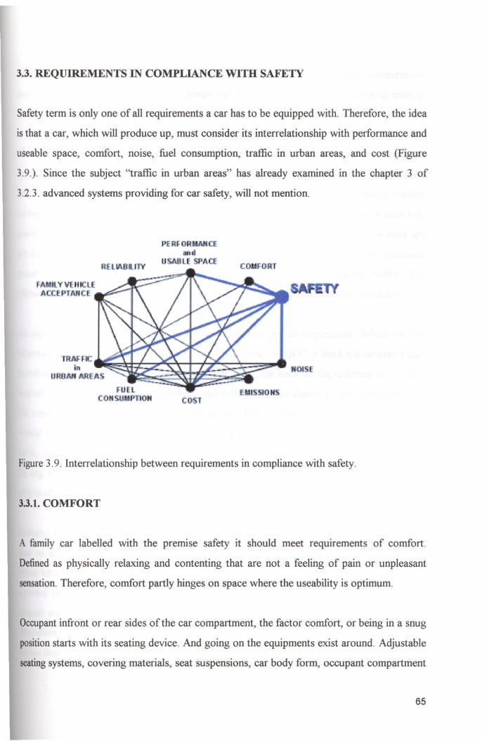
3.3. REQUIREMENTS IN COMPLIANCE WITH SAFETY
Safety term is only one of all requirements a car has to be equipped with. Therefore, the idea
is that a car, which will produce up, must consider its interrelationship with performance and
useable space, comfort, noise, fuel consumption, traffic in urban areas, and cost (Figure
3.9.). Since the subject "traffic in urban areas" has already examined in the chapter 3 of
3.2.3. advanced systems providing for car safety, will not mention.
I
Figure3.9. Interrelationship between requirements in compliance with safety.
3.3.1. COMFORT
A family car labelled with the premise safety it should meet requirements of comfort.
Definedas physically relaxing and contenting that are not a feeling of pain or unpleasant
sensation.Therefore, comfort partly hinges on space where the useability is optimum.
Occupantinfront or rear sides of the car compartment, the factor comfort, or being in a snug
positionstarts with its seating device. And going on the equipments exist around. Adjustable
seatingsystems, covering materials, seat suspensions, car body form, occupant compartment
65
air space freshness, humidity, and the average heat temperature inside compartment,
suspensions, and all other acceptable design features meet the anatomical neediness must be
in exact conformity with occupant.
Since during travelling an occupant in touch with seating elements, and due to breathing, the
inner area humidity and temperature rise up and rate of oxygen rises down. The film area
among the hip and seat outer surface must be bounded in a constant level as nearly possible
as between 19.0 and 26.0 degrees Celsius so that the occupants take their short or even long
travel without felling any discomfort and ennui causing by perspiring. For the humidity and
air freshness, the cooling system must be applied in occupant compartment on instrument
panel either automatically or manually by rotating or pushing on-off switch button. The
climatemust allow the human body to be at any humidity from 10 percent to 70 percent.
As signed, one of importance of the comfort elements are as suspensions. When the first
wheeled transportation systems were introduced around 3500 B.C. it need not contain a high
comfort due to aiming at carrying the loads only. But, the need for the reducing the shaking
started with smoothing the road surface, and followed by insulation of the bodywork from
the road wheels. Then, in its development period, first examples appeared as a system that
would base the modem springing systems being called suspension is just like an upturned
table.And it functions only to move body and wheel separately. The concept was replaced
by big C-shaped spring and it is phased out by powered car developments changing to
ellipticallyshaped one.
Initially,the principles of the suspensions is to make keep the wheel adjacent to the ground,
and to achieve extreme insulation from the vibrating resulting from irregular movements
whenhitting a bumpy surfaces. Shock pressures in those situations move the wheel directly
upward or make the wheel sprung and then movement as momentum transferred to the
chassisand the body. The movement upward turns back by the car body gravity so sharply.
Therefore, springs are placed between the wheel and chassis since moving upward less
ratherthan wheel. The utmost importance of the suspension is being designed considering its
ilMlR YUKSfK TEKNOlOJi ENSTiTUSO 66
REKTORLUGU

movement frequency being coincided with the frequency of the wheel's vertical acceleration.
But, significantly, in that acceleration together with wheel, the force could exceed the limits
enough to lift the wheel off the road. So, the suspensions are not only made of springs but
also it contains the damping device using the friction to dissipate the force or energy.
Struts as, used here, hydropneumatic suspension components are attached to the chassis by
its upper end and affixed at the lowest to the carcass of the tire. To fix and not to swing the
spring around strut used a heliozoan base. The conceptual design of the suspension system
either active by adding an actuator, a pump, an accumulator and an electronic valve or
passive ought to remove the verbose loads from the car at the shortest time as possible by
tires. Hence, how important a suspension for driving stability, is realized especially in the
event of inefficient of distributing and condensing load on each axis around tire (Figure
3.10.). Such that, it will make at least one side of the car collapse and probably will ensue a
rollover crash with very a familiar consequences of jeopardy as a result of malfunction in
veering a curve on the road.
Figure3.10. Schematic of effect of suspension system in Family Car in side-bisected view.
67
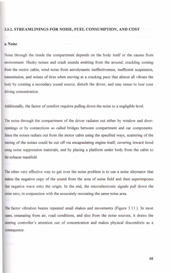
3.3.2. STREAMLINlNGS FOR NOISE, FUEL CONSUMPTION, AND COST
a. Noise
Noise through the inside the compartment depends on the body itself or the causes from
environment. Husky noises and crash sounds emitting from the around, crackling coming
from the motor cabin, wind noise from aerodynamic ineffectiveness, inefficient suspension,
transmission, and noises of tires when moving at a cracking pace that almost all vibrate the
body by creating a secondary sound source, disturb the driver, and may ensue to lose your
driving concentration.
Additionally, the factor of comfort requires pulling down the noise to a negligible level.
The noise through the compartment of the driver radiates out either by window and door
openings or by connections so called bridges between compartment and car components.
Sincethe noises radiate out from the motor cabin using the specified ways, scattering of the
waving of the noises could be cut off via encapsulating engine itself, covering inward hood
using noise suppression materials, and by placing a platform under body from the cabin to
the exhaust manifold.
The other very effective way to get over the noise problem is to use a noise alternator that
makes the negative copy of the sound from the area of noise field and then superimposes
that negative wave onto the origin. In the end, the microelectronic signals pull down the
noisezero, in conjunction with the accurately recreating the same noise area.
The factor vibration beams repeated small shakes and movements (Figure 3.11.). In most
cases, emanating from air, road conditions, and also from the noise sources, it draws the
steering controller's attention out of concentration and makes physical discomforts as a
consequence.
68
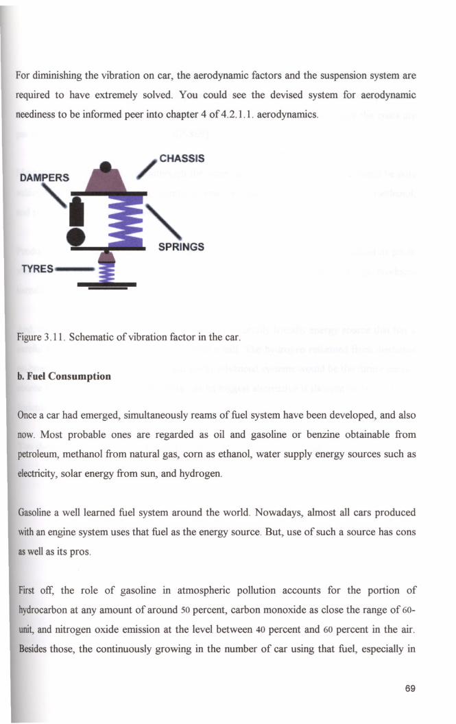
For diminishing the vibration on car, the aerodynamic factors and the suspension system are
required to have extremely solved. You could see the devised system for aerodynamic
neediness to be informed peer into chapter 4 of 4 .2.1.1. aerodynamics.
DA
TYRES
CHASSIS
Figure 3.11. Schematic of vibration factor in the car.
b. Fuel Consumption
Oncea car had emerged, simultaneously reams of fuel system have been developed, and also
now. Most probable ones are regarded as oil and gasoline or benzine obtainable from
petroleum, methanol from natural gas, com as ethanol, water supply energy sources such as
electricity,solar energy from sun, and hydrogen.
Gasolinea well learned fuel system around the world. Nowadays, almost all cars produced
withan engine system uses that fuel as the energy source. But, use of such a source has cons
aswell as its pros.
First off, the role of gasoline in atmospheric pollution accounts for the portion of
hydrocarbonat any amount of around 50 percent, carbon monoxide as close the range of 60
unit,and nitrogen oxide emission at the level between 40 percent and 60 percent in the air.
Besidesthose, the continuously growing in the number of car using that fuel, especially in
69

the industries having least clean technologies, would make the greenhouse effect in the air as
well as its life threatening effects. The physical and financial properties should compare with
the other energy sources, the consumption level accurately seems lower, and the costs are
par on with each (Mason, 1990, pp. SP-869).
Methanol and ethanol sources although the same cost with the gasoline, a car could be only
achieved at the amount of mpg, stands for mile per gallon, a half times more for methanol,
and twofold the fuel for ethanol.
Producing a car completely use of electric in the form of electricity, the pros added its profit
statement as saving the energy around 30 percent of primary energy, although produces
harmful emission.
And, as for the hydrogen ... It is the most environmentally friendly energy source that has a
careful consuming of the energy as of 2 with a half The hydrogen reformed from methanol
on-board using advanced fuel cell. That costly advanced systems would be the future energy
source since the majority of solar energy as its biggest alternative is thought to be use in the
agriculture.
You should look for more information to the chapter 4 of 4.3.1.3. engine.
IllMIR YUKSEK TfKNOlOJI E1~Sl'liUSUI
I RfKTORlOGU I
70

CHAPTER 4 PORING OVER A CASE
4.1. AN OVERVIEW OF PROJECT
Under the definitions for creating the concept family car within limits, the project aims to
present most appropriate model, and assumes to allow the person to drive it and to travel in
safest position.
As introduced notable safety requirements for the car almost overall parts of the title, here,
the project will be discussed with its design criteria, also benefiting from technical terms
defining its meanings.
In the era leading up to Family Car Concept, naturally, there have been in an increase of
variations of the sketches and the first renderings so that proportions of safety requirements
could be correctly caught in shape. Therefore, the project would not eliminate the
alternatives (Figure 4.6., Figure 4.7. ), would make a way of briefing them, but will be focus
on the basic model (Table 4.1., Table 4.2., Figure 4.1., Figure 4.2., Figure 4.3., Table 4.3.,
Figure4.4., Figure 4.5.).
In design process, specified neediness is targeted the consumer as Turkish young family
group and its common lifestyle regarding general structure of that. ( Chapter 1 of 1.1.1.
identification of Family Car, page 7-10). Here, it would be useful for discussing and briefing
onwhat structural basis were thought of reflecting within and whilst projecting the title.
In the period of time starting 1923 and continuously leading up to now, having oriental
culturehas become aggressive one. Especially, the date in 1982, injecting and constructing
new structure in commercial area directly aimed at revaluation the life of Turkish family.
Additionally,constructing the idea on the concept as market economy which reaches every
individualwith a tremendous organization has been replaced and turned over to that of open
market which serves the groups by reducing production cost on account of build-up
71

consumption, and increasing fiscal structure. That passIOn of commercialism, however,
strictly effected the main kernel of family life and caused it to be more condensed and
smaller in number.
Those all accumulation of experiences over changing in general marketing perceptiveness
reflected on certain sectors. As a one of that, automotive sector, having a widen
organisation scope, gradually used those way to the point for selecting targeting group for
whom manufacturers produce the goods by intensely putting the technological
advancements on current interest. Should we coincide each one, direction of future
commercial region clearly will be directed to the side of group as family with supposition of
making someone, or consumer as used here, induce or belong as much in any number by
making a select on big portion on that unit.
Those commercial reasons are counted as only one of all criteria basis for selecting new
structure, new manufacturing method, and a new one category. Using that databases as
stated above, design features being used in converging with the Turkish young family social
lifein use within esthetical proportions and reflecting them through the form concept of the
designencompasses following explanatory words:
• The concept for approaching the design has considered minimalism by using small
components, but in highly efficiency, being able to do their tasks successfully. As for the
car small in size, especially interior design simplified from its complexity for gaining
acceptable space such that occupants will feel themselves snug, also with taking the
advantages of sufficient cargo area in the luggage with a capacity of 72 kilograms, or
16opounds.
• Car designated as Dainty has established by volumetric size of 3100x1527x1590mm3.The
concept oriented towards emergence of side front doors with a hatchback (3-door
bodystyle). The doors are designed to be easily detachable so that it would help for
extricating the victim of an accident from the situation being in extremis.
72

• Form of the vehicle signs the personae of designer. While projecting it, as said, young
family prototype was also thought of having an adapted lifestyle to the new commercial
culture and its all necessity. Project is constructed on a way of mounting and placing
devices such as front apron and front spoiler being smoothed with the surface of outside
of the car, and even with body color. But, as headlamps, tail-lamps and signal lamps, the
form was used to emphasize those only by reasons for making a complete opposite on
formal congruence, and describing like an eye in symbolic meaning. So, the method of
approaching external space of the car is based on the form concept as ''from general to
special", in contrary, in interior compartment design, tenably, on the concept as "from
special to general".
We believe that the advantageous of contrast is always aside the small structures. So, even a
headlamp may become dominating if others are only used to provide for condensing the
perceptiveness onto the object. As here, hood surface, in a way, that covers the up-edge of
front lamps in the sense of using counters as the tool of design trade, and whole.
Becoming narrower through the side of the rear portion of the vehicle is assumed to cause a
unobstructed seeing, even at dark point. On countered side, the form remains to be done by
a finish-element that would replace with rear side doors, in the concept of hatchback model.
Asbased on safety and aesthetic concerns, barely rear occupants, children as here, is clear of
dangerous position, and need not worry about thinking of the doors fully closed or not.
Especially, concave forms outward and convex forms inward are in extreme effectiveness for
safer form construction. They contains compact concern, and would be a base for easily
attachable, detachable, and even refuting blandness to the side of innovation so that a new
designspots easily could be caught and could be redesigned. It is cited that form building is
an action of taking pains over body. And that we are entirely seeing eye to eye with the
theory of a car should be design and buildup onto a rectangle form near to square which
provides to be correct in aspect to engineering concerns. Habits, such as using light but
73
decked and twisty contours on goods could be reflected the form criteria within esthetical
concerns.
• The book written on cars in the title of "Araba Sevdasl" by Recaizade Mahmut Ekrem
basically tells our nation having the passion on cars as a decked device. Seeing that, fully
embellished with reams of words or linen material, and accepting a car as a second home
caused to a new type of mass transportation means under the name of shared taxi
(dolmu~) that has not yet been done other countries. As it is, but more strictly configured
a family car would response the family needs as private personal transportation mean.
We recommended that the old type of those vehicles should be completely discarded and
the use of family car should be phased in. So, there is no need for using alternative ones
anymore.
The rules are the same as the world acceptance. But vehicles are required to be have body
more off land in parallel to the road and geographic conditions, solving the complexity of
aerodynamic efficiency with leveling devices.
As easily caught in name of the vehicle it should reply the requirements of children. As a
way, we thought that how successfully cultural tendencies might be imitated within family
car design. Coming in mind, stock characters of Turkish shadow theatre would have been
echoed on a film display consisting of a bar that secures electric and electronic articles and a
squareflexible movie screen wrapped around the bar itself with the size of 30ox30omm2, and
all system located at any side pane-frame with the property of one-point-rotating for easy
controlling and folding property on convergence with advanced material and with its points.
Another adjustable mini camera would superimpose the digital picture on that screen and
will play the action. We think it would be very useful for children who really disturb
psychologically in a long car travel, even at short distance, due to the feeling of being
tautened in a covered compartment. Since the system controlled by the driver easily, being
small in dimensions and stated rear seating position, it would not cause any driving
degradation or any faults by system.
74
Other specifications (Table 4.1., Table 4.2.):
SPECS OF DAINTY VEHICLE
Struts, arc-shaped lower Rear Suspension
arms, coil springs, tube
Curb Weight kgs
Torque
Wheelbase, mm.
Length- Width-Height,
nun.
Engine
Front Suspension
700
82/3100
1946
3100x1527x1590
999 cc
gas-pressure
anti-roll bar
shocks,
HP
Weight Distribution
Track fir, mm.
Aero. Drag
Cylinder
67
60/40
55.6158.8
.21
4
Semi-trailing arms, coil
springs, twin-tube gas
pressure shocks, anti-roll
bar
Steering Rack&pinion, engine Steering RatiolTurning 15.4: 1/32.8
speed sensitive power circle ft.
assist
Brakes
Top Speed
Transmission
Rev.
11.3" vented front/l0.7" Acceleration,
solid rear
km.h, see
162kph (limited, speedo
Fuel Capacity
says 160) ZF Type C, 5 speed
Ratios: 1st
2.49:1
3rd
1.24: 1
5th
3.85:1
Final Drive 0-160 11
60 litres (fuel tank under
rear se'!t)
4.21:1
1.66:1
1.00: 1
3.15:1
Table 4.1. Specifications of Dainty Car.
----_._.-rZM1R YUKSEK mNOLOJi.E~SlirOSD iI ~ i;tiJP~",:;/D;k~m~n~Q~V~~U50i, 1 B,lI
75

EXTERIOR FITMENTS OF DAINTY CAR
Outside mirror case in car colours
Bumpers in car colours
White side indicator lights
Roof antenna
Central locking system
Ready-to-drive spare wheel
Activated carbon filter
Central locking system remote control
Steel 6Y2J x 16 wheels with wheel covers, 205/55 R Rear fog lamp
16 tyres
Open-door warning lights
Adjustable-range headlights
Front windscreen wiper with 4-stage interrupt option
"Monte Carlo" wheel pack 4 light metal 6Yz J x 16
wheels, 205/55 R 19 tyres, hub caps (for front)
"15" wheel pack 4 steel 6Y2J x 16 wheels, 195/60 R Anti-theft alarm system with interior surveillance
20 tyres, hub caps (for rear)
Fog lamp Heatable front screen-wash jets
Remote opening system for luggage space and tank
cap
Table4.2. Exterior fitments of Dainty Car.
Dainty Car presents high performance through road conditions within global perceptiveness
as small which adds the car frenetic flexibility on curve parts of lane portion of the road for
encumbering swerving, in parking areas, and in event of any traffic congestion in city. As not
compressed down, and has enough space of interior with ergonomically enough components
providing anatomical requirements, it provides relax travelling, easy drive, and maximum
snug for occupants. Also the car supports the body by using hard shell as well as
aerodynamic effectiveness for steering stability heeding jolts led on to by longitudinal,
vertical, and lateral airflow forces. Inboard and outboard surface, the car is assumed to be
outfitted with dependable driving accessories and hardware. Such as, automatically
strengthened seat belts assembled to adjustable steering wheel, bucket seats with vertically
and roundly self-aligning head restraints, a very unadorned dash board, gutsy designed
chassis,leveling devices, an innovative windshield wiping system, redesigned sun visors, and
others.
76

_____ 1 Bianca WhOte
Cherry Red
Evergreen
latinum S-Iver
Storm Grey
Sapph-re Blue
Tuscany Green
Crysta Green
Cia 10 Red
Figure 4.1. Color range of Dainty Car.
It uses an environmentally friendly small engine that fuels hydrogen as basic energy source,
but easy adaptation for coming next the car will equipped with multi-fuel concept taking
secondary fuel as gasoline.
77
4.2. STRUCTURE OF CAR
4.2.1. DISTRIBUTION OF CAR STRUCTURE
Very common car parts alone consists of the following categories:
• Body,
• Chassis,
• Engine,
• Front and rear axle,
• Master cylinder, reservoir and brake lines (will not be mentioned), and
• Transmission (will not be mentioned).
4.2.1.1. BODY
As first introduced above, body itself, should it is thought as a finish element with its interior
of complete structure, combine the aerodynamic factors to aesthetic proportions into one.
Originally, as body of car built up solely to protect the occupants from inclement weather
was the case earlier with horsedrawn coaches. And also its design supposed to gain as much
space as possible for occupant being under weigh condition. That is the reason how likely
the body was to be changed over the period of one hundred years (Seiffert & Walzer, 1991).
After a while, since having increased serious to fatal injuries year by year as a result of
accidents, car body became important factor for restricting damage of crash through interior
compartment. Not only one factor, also paramount importance of reducing fuel consumption
and the aerodynamic side of styling with aesthetic proportions that both have adequately
predominate on body design. However, since designs become more productive via technical
stakes, the factor of aesthetic has emerged as the most considerable to the consumer's broad
socialconcerns. Hereby, energy conservation and others have not assumed as primary gains.
78
In Dainty car, body takes properties of the mono-coque hard shell concept (Chapter 4 of
4.2.1.1.2. structural concepts, page 83-84). The concept utilizes a rigid exterior as identical
as rigid interior compartment of conventional cars. In case of a collision, the rigid concept of
the smaller car causes the less rigid deformation zone of the larger one to yield and absorb
the energy. It should be cited that Dainty hard shell concept contradicts others since
traditionals support less rigid deformation zone outboard and rigid deformation area inboard
car. It must do so, because front area of the Dainty car or boot portion outermost the car,
since the motor became merest, has not enough deformation zones (Riley, 1994).
Dainty body basically consists of outboard elements as hood, trunk, pillars, window frames,
windshield, rear and side windowpanes, sunroof, and doors. That all could be also counted
as finish-elements including front and rear apron, spoilers, and lamps.
So, whole outboard element cover a content mostly discerned as belows:
• Either both outboard and outer side or exterior as finish-element.
All styling and compounding outboard elements in concept of mono-coque that are in
compliance with each of all are required another study as aerodynamic.
4.2.1.1.1. AERODYNAMICS
Aerodynamics is the poring through the way in which the objects recede for a place against
the air. The aim is to make the airflow off exterior surface of the car.
Aerodynamic design through the car body has been implemented via three factors. These
are:
• Frontal area of the car,
• The square of the air velocity in the airflow direction, and
I!ZMIR YUKSEK TEKNOlOJi ENSTirOsO
i REKTORlUGU
. V',h:"hnne ve DOKlimontasyon Deil\) 3~k.- ." _.-- -.-.-. ~.""-.q .--"' .•._~.~.~_ •••....-
79

• The shape of the body with a specified coefficient of aerodynamic drag as CD.
First off, together of three factors directly influence the driving stability, handling, fuel
consumption, and the speed of the car. The first of three factors is not supposed to effect
aerodynamic ability of the car positively since car interior shape depends on the generation
that becomes huger in size by years. But, the others have highly intense effectiveness as
mentioned, in which the shape of the body with its design limits must be defeated or
minimized the effects resulting from air forces.
Rear window ang eIn de rees
o
: 0,10>QuI::
g' 0,20~(J
20 22 24 26 28 30 32
[ [
Family Veh·cle rear window value
Figure 4.2. Graphic of Dainty Car rear window value.
As seen, figure 4.2. prepared utilizing from the test outcome tables for the project car. It
shows the drag coefficient or CD value of nearly 0,21 is acceptable for aerodynamic
efficiency and under the limits of 0.3 of CD. But, it is cited that especially after rear end
degree of 62 the CD value does not make so respectable effect on car aerodynamic. If so and
over, it should only reply the design criteria for aesthetical proportions as in figure 4.3.
80
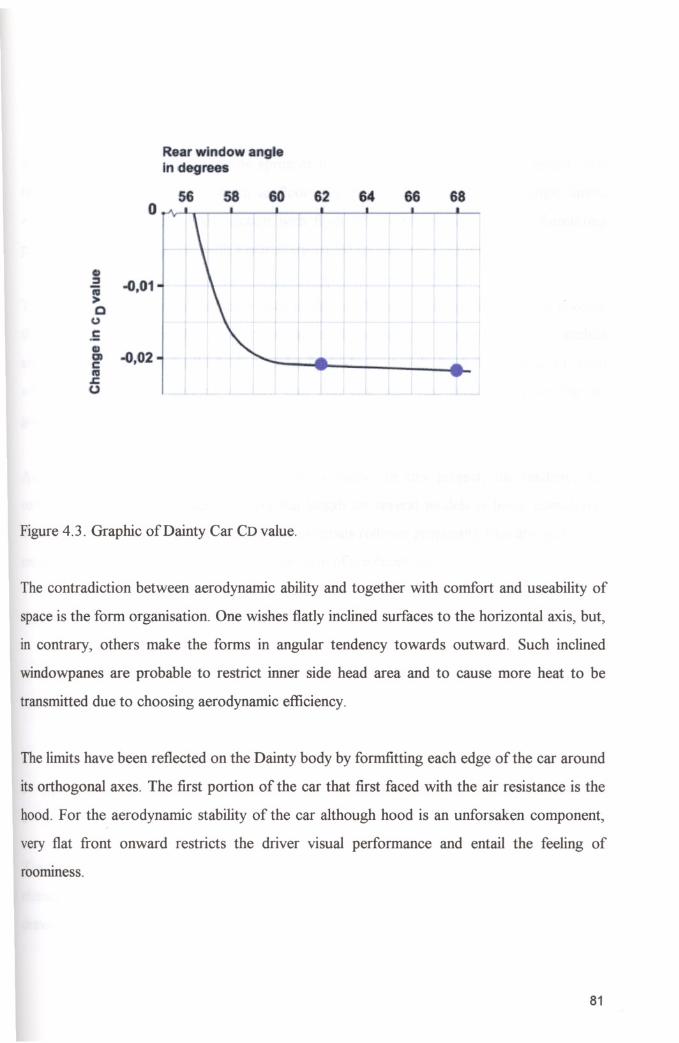
Rear window ang ein· egree
:::J..0.01J cQ.E
g)
-0,02c: IVs=0
Figure 4.3. Graphic of Dainty Car CD value.
The contradiction between aerodynamic ability and together with comfort and useability of
space is the form organisation. One wishes flatly inclined surfaces to the horizontal axis, but,
in contrary, others make the forms in angular tendency towards outward. Such inclined
windowpanes are probable to restrict inner side head area and to cause more heat to be
transmitted due to choosing aerodynamic efficiency.
The limits have been reflected on the Dainty body by formfitting each edge of the car around
its orthogonal axes. The first portion of the car that first faced with the air resistance is the
hood. For the aerodynamic stability of the car although hood is an unforsaken component,
very flat front onward restricts the driver visual performance and entail the feeling of
roomIness.
81
The rests are as follows:
Smooth-faced front end, front body apron or front fender with integral elastic spoiler, rear
fender with aerodynamic transition to floor pan, windshield within shallow angle limits,
elliptically shaped upper body section with flush side windowpanes, rounded-formfitting
pillars, hatchback integrated with a rear sharp-edged spoiler, and countered top.
The spoilers are of paramount importance to the car. Barely, front spoiler supports heeding
the airflow leaking parallel to trajectory of travel of the car or its longitudinal axis, to deflect
any turning moment under the body in order for body not to jolt. Such that, unless it is used
efficiently, it diminish steering stability. Not only one, also rear spoiler provides the car
going the distance for lessening swerving.
Aerodynamic design directly effects the body shape. In this project, the tendency for
rollover, resulting from shape with vertical length on several models is being considered.
The own study for aerodynamic effectiveness versus rollover propensity basically quantified
on each shape point that relatively trues the form of the family car.
4.2.1.1.2. STRUCTURAL CONCEPTS
A stiff infrastructure on which the bodies rested could be extricable into three different
structural concepts to build a car as follows:
• Traditional Steel Concept,
• Space Frame, and
• Mono-coque.
Traditional Steel Concept discerned as Uni-body or Body-In-White that the structural
elementsconsist of beams, columns, and inner and outer panels. The steel elements are deep
drawnfrom cheap semi-finished plate material, and jointed together in a self-carrying body.
82
The technologies involved are well developed, and production costs are minimal. On the
contrary, the concept with which car constructed takes the disadvantageous of:
• Requiring a lot of assembly operations,
• Structuring with full of discontinuities, and
• Being heavy in stead of opportunities and improvements coming in use for weight
dwindling.
In another structural concept as Space Frame, the load carrying structure is separated from
the exterior body panels. The body panels can therefore take the advantageous of:
• Being made in light weight materials,
• Designing differently from the load carrying space frame (as the model Audi), and
• Using profiles as semi finished parts since the space frame is independent from the
design.
A big difference in this concept is the replacement of steel by composites in some of the
panels. Such as, GMT in wheel housings or bottom panels due to giving a smooth shape to
it and SMC in outer panels because of attainability of a smooth surface.
Finally, In concept of Mono-coque, using of body panels and load carrying elements are
integrated in one structural element. In condition of throwing weight of advanced
composites for producing integrated elements, it is possible to save weight as well as highest
structural effectiveness. Therefore, mono-coque as a triumph of ingenuity and experience of
the designer using which manufacturing technique is well available for cars that are small in
size as in Dainty body.
Mono-coque is a combination of carbon fibre and glass in epoxy matrix. Allowing the
components with no sub frames gains easily removable parts for bodywork or in the event of
a collision, less space, less parts, and incredibly strength efficiency (1816 ft kgs/degree),
perfectweight distribution, and performance not at the cost of safety.
: !ZMIR YUKStK TEKNOlOJi EJ.STlTUSO
I REKTORLOGO
! r/ltflnkn;)t! VP 1l1\~li. nnt;l(\!f\Q l," t:'\ 9.t~
83
Strength efficiency when designed energy absorbing zones in passenger compartment, any
damage to the monocoque zone could be limited to the visible areas of failure. Repair of the
system needs specialist repair, but it does not require a difficulty of unduly expensive
undertake.
Seat attachment to the mono-co que body as the same as evaluated in the chapter 3 of 3. 1.1.
restraint systems of seats. Additionally, the vertical and horizontal carcasses of the seat
could be attached via same attachment or by using different attachments onto the fleet of the
chassis.
4.2.1.1.3. BODY INBOARD
Whole content, enclosed via outboard elements, mostly regarded as described belows:
• Either both inboard and inner side or interior as occupant compartment.
Inboard of the whole car is the most essential part since comfort, enjoyable feelings, steering
pleasure, and almost all driver and occupant needs must be met. To achieve this from
infrastructure of design to the components that the user touch, seats, perceives, feels and
sees. Design range for the latter since much pleasure to the designer, wide variety of
products and solutions could be easily soared.
It is also the area that the form of out integrated to the inner side. Specifically, the essential
criterion for the inner in design is to catch the idea of seeing each component soft, in form,
material, texture, also in colour. Plastic materials inboard surfaces could easily achieve all
requirements above. Nowadays the use of plastics or materials obtained from that has
reached (up to 26 kilograms (Hiirriyet Gazetesi, October 30th, 1998, pp. 20».
For example, the seats are designed in the concept like baseball catcher's, as though it
caught the energy and then draws it down.
84
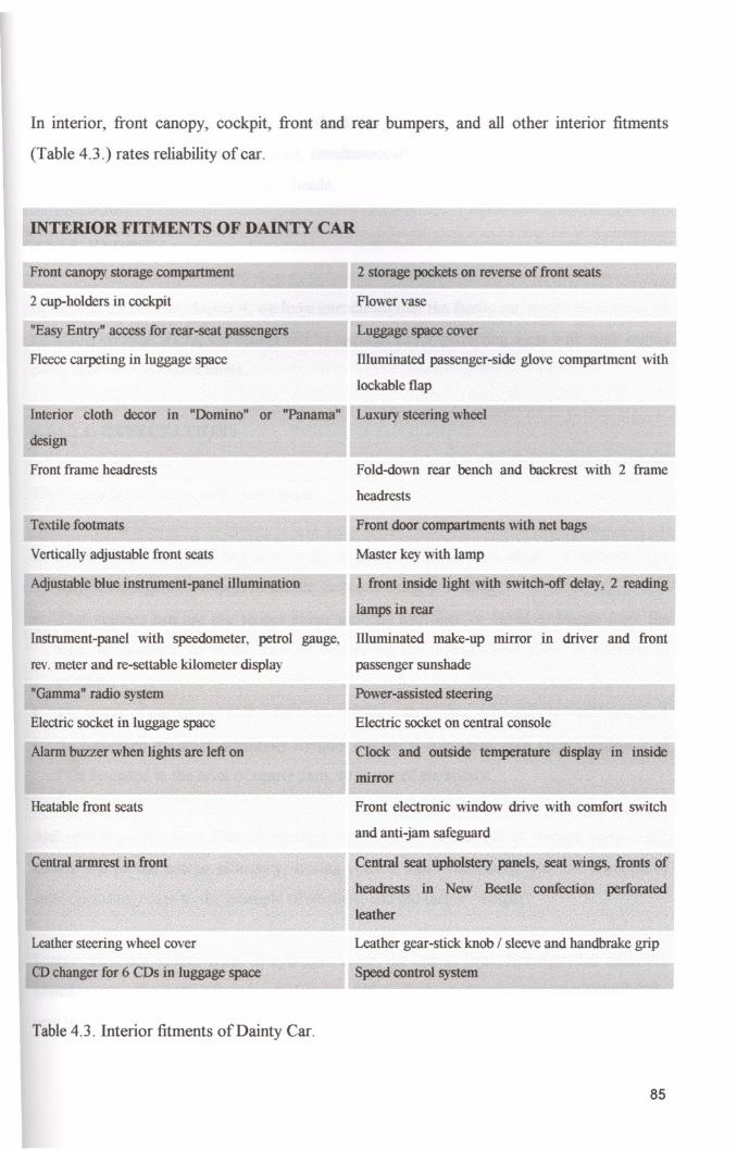
In interior, front canopy, cockpit, front and rear bumpers, and all other interior fitments
(Table 4.3.) rates reliability of car.
INTERIOR FITMENTS OF DAINTY CAR
Front canopy storage compartment
2 cup-holders in cockpit
"Easy Entry" access for rear-seat passengers
Fleece carpeting in luggage space
Interior cloth decor in "Domino" or "Panama"
design
Front frame headrests
Textile footmats
Vertically adjustable front seats
Adjustable blue instrument-panel illumination
Instrument-panel with speedometer, petrol gauge,
rev. meter and re-settable kilometer display
"Gamma" radio system
Electric socket in luggage space
Alarm buzzer when lights are left on
Heatable front seats
Central armrest in front
Leather steering wheel cover
CD changer for 6 CDs in luggage space
Table 4.3. Interior fitments of Dainty Car.
2 storage pockets on reverse of front seats
Flower vase
Luggage space cover
Illuminated passenger-side glove compartment with
lockable flap
Luxury steering wheel
Fold-down rear bench and backrest with 2 frame
headrests
Front door compartments with net bags
Master key with lamp
I front inside light with switch-off delay, 2 reading
lamps in rear
Illuminated make-up mirror in driver and front
passenger sunshade
Power-assisted steering
Electric socket on central console
Clock and outside temperature display in inside
mUTor
Front electronic window drive with comfort switch
and anti-jam safeguard
central" seat upholstery paneis,:seat wings, fronts of
headrests· in New Beetle confection perforated
leather
Leather gear-stick knob / sleeve and handbrake grip
Speed control system
85

In this project, installing a pneumatic roof entirely prevent the occupant from being injured.
It is thought when an airbag activated, simultaneously sensors ignite the system and blows
up it forward towards the occupants' heads.
4.2.1.2. ENGINE
In the first part of the chapter 4, we have introduced that the family car would be running on
multi fuel concept. Here, the causes will be introduced for perfecting a car with such engine
using such source within limits.
4.2.1.2.1. EXPECTATIONS
The causes for selecting hydrogen engine:
• Structure of hydrogen engine typically similar to the gasoline engine. Therefore, it is
very advantageous to adapt to the car currently being producing,
• That engines can use the source either gaseous hydrogen or liquid hydrogen from the
tank or on-board, or in the form of bonded on the titanium-iron alloy, in addition to
gasoline,
• The usage of energy per unit volume are significantly higher, especially in liquid one, and
• As embraced an environmentally friendly engine, if compared with others emission of
C02 bounded in the level of nearly zero, as in use of electricity.
And selecting one, from four alternatives of the same source, of its storage types basic
criteria will be the energy efficiency, storing volume when comparing with the criterion of
same operating range to the example of smallest, and the factor ''weight''.
Energy efficiency of four types of hydrogen using, the one as liquid hydrogen has takes the
advantageous of criteria of source hydrogen. Although the hydrogen on metal hybrid TiFe
very being an efficient storing, it would require unnecessary loading and occupancy onto the
86
car since its weight rated with auxiliary components such as protecting elements, or device
utilising for servicing.
Storage of liquid hydrogen used an isolated one named cryogenic tanle The cryogenic tank
is a heat insulated-double wall constructed tank and so that keeps the temperature of
relatively -253 degrees Celsius. The temperature should make zero or compensate for the
pressure from the volume inside as a result of heating. For that reason the isolation perfected
to a level of three hundred times that of a material as styrofoam. Insulating materials for the
tank consist of aluminium foils and glass fibber paper (Seiffert & Walzer, 1991).
Within the similarity as conversion of chemical energy into mechanical energy, the engine
could be accepted renovated, or better, modified gasoline engine. Modifying is only adding
fuel supply devices as a cryogenic tank and an evaporator for liquid hydrogen, as in family
car, and in its mixture formation. Needy to say, since the hydrogen being in air from the
range of 5 percent to a highly intensely range of 75 percent, ignition operation is possible for
any range.
87
CONCLUSION
Developing a complete understanding of human behaviours makes relieve the demand sides
of the unacquaintance in design process. By the way, in family car the term safety are must
have seen each elements in the no contradiction with unadorned design perceptiveness.
Carrying out such concept not only has provided the criteria of usability, comfort, ease of
accessibility, visibility, and frenetic performance, it also rated the passive safety of whole
design in conjunction with that. But, minimalist theory in geometry, mass, and volume of
the family car has signed the number of risks so-called rollover propensity at juncture, on
curved parts of the lane, and having insufficient deformation zone, especially in rear-end.
Here, choosing the alternative material as reinforced composites, fibreglass, makrolon
already lost the mass advantage of the car regained by stitfuess. The statistical results also
provide our concept (Chapter 2 of2.1. light car safety in perspective).
Modem technology with reinforced material also allows producing the very curved forms so
tangible to the users. Utilizing those technological advantageous, we shaped the outer and
interior surfaces smoothly. In doing so, predictable effects of the sharp edges, peak points
were completely defected.
Being low-mass can assumed to take the risk of propensity. But, the causal factors propel
the dynamic tendency for a rollover, is the velocity at curve parts, center of the gravity,
friction between the land and tires, shape, the verbose loads not removed as a result of
inefficient suspension design, and mass, and others. As wished, it was not the basic factor
alone. So, making changes on other components equals the disadvantageous of lightness as
widen surface of tires tangent to the land as Indy car, reducing the motor capacity
consequently reducing the velocity, using full time four-wheel drive with variable torque
ratio between front and rear axle, and so on.
The concept of multi-fuel is a must-have need for commg up to year 2030. Since the
completely for a new technology, the world is not be readied. The best way for introducing
98

the different technology to the users is to make such prototypes. Besides that, the energy
sources and air pollution added the concept viability.
In inner design all design should be focused on the things in high conjunction with driver and
occupants. Especially, for driver and steering stability driver positioning area should be rated
in space intensity, all design equipments, also safety features for that location should be
secured around or new one should be added the characteristics of existings. Instead of new
one, redesign of all exists. Then, new designs, new proportions and new meanings on them
could completely change the design concept in car. Briefly, reams of redesign is not resulted
in same shape, same features, it helps to reach a entirely new one. Also, it provides pure,
simply, but efficient conformity and safety.
Essentially, "the real test starts when the driver takes the wheel". With an inefficiently
constructed "safety map" on car seems to a man has no eyes, ears, and noise. Aiming that,
Safety Map of the project should be prepared and the intensity of design should be directed
whilst utilizing it.
As a critic, common designs which take the characteristics of human shape. For its
functionality to be in parallel to the human needs could be, but every object candidates to
being a part of our life should have their own forms, and identity.
99
GLOSSARY
INTRODUCTION
A means refers to transportation device has ability to go distance using fuel.
Vehicle refers to a special kind of transporter with motor driven by mechanical power and
manufactured primarily for use on public streets, roads, and highway, but does not include a
car operated only on rail line.
Vehicle safety means the performance of a motor car or motor car equipment that protects
public against unreasonable risk of accidents occurring because of the design, construction,
performance of a motor car, against unreasonable risk of death or injury in an accident, and
includes nonoperational safety of a motor car.
CHAPTER 2
CV refers to a parameter in terms of coefficient of variation used for determining the
repeatability of test results such that a lower % of CV imitates a more repeatable result.
Vehicle equipments refers to any system, part, or component of a car as originally
manufactured; and any similar part of the component manufactured or sold for replacement
or improvement of a system, part, or component, or as an accessory or addition to a car; or
any device or article or apparel that is not a system, part, or component of a car and is
manufactured, sold, delivered, offered, or intended to be used only to safeguard cars and
highway users against risk of accident, injury, or death.
One land mile a unit of distance is equal to 1760 yards or 1609.35 meters.
One pound a unit of weight is equal to 0.454 kilograms.
100

CHAPTER 3
Accelerator means a pedal that you press with your foot so as to make the car go faster.
Bulb-check means illumination of each gauge or telltale checked when the headlight or
ignition switch is activated, or during car starting.
Clutch means a mechanism that enables power from the engine to be disconnected from the
drive shaft in order to allow you to change the gear. Also it can be refer to the pedal that
you press before changing gear as the clutch.
Forehead impact zone means the part of the free motion headform surface area, determined
the according the procedure listed below:
• Position the headform so that the base plate of the skull is horizontal,
• From the centre of the threaded hole on the top of the headform, draw a 69mm line
forward toward the forehead, along the contour of the outer skin of the headform. The
front end of the line is designated as Point P. From that point draw a lOOmmline forward
toward the forehead, along the outer skin of the headform. The front end of the line is
designated as Point Q,
• Draw a line 125mm line which is coincident with a horizontal plane along the contour of
the outer skin of the forehead from left to right through Point Q so that the line is
bisected at Point Q. The end of the line on the left side of the headform is designated as
Point a and the on the right as Point b,
• Draw another 125mm line which is coincident with a vertical plane along the contour of
the outer skin of the forehead through Point P so that the line bisected at the Point P.
The end of the line on the left side of the headform is designated as Point c and the end
on the right as Point d,
101
• Draw a line from point a to Point c along the contour of the outer skin of the headform
using a flexible steel tape. Using at the same method, draw a line from Point b to Point
d,
• The forehead impact zone is the surface area on the FMH forehead bounded by lines a
O-b and c-P-d, and a-c and b-d.
Gauge means a display in which the device measures the lashings or quantity of something
and shows the amount measured. Such as temperature gauge, pressure gauge.
Greenhouse effect is the problem caused by a built-up of gases such as carbon dioxide in
the around the earth. These gases trap the heat from the sun, and cause a gradual rise in the
temperature of the atmosphere.
Headform means head itself
Head orientation reference line refers to a horizontal SORL stands for Seating Orientation
Reference Line through the Point Z.
Telltale means a display that indicates the actuation of a device, or correct or defective
functioning or condition, or a failure to function.
Whiplash injury means the motion of the head and neck relative to the torso and the
associated neck injuries occurring when a car is struck from the rear. Symptoms of the pain
in the head, neck, shoulders, and arms may be associated with damage to muscles, ligaments
and vertebras. Onset of symptoms may be delayed or mat last for a prolonged period.
One gallon is the unit of measurement for liquids nearly equals to 3.785 litres.
102

CHAPTER 4
Front and rear apron could be described as fender mean part of the body forwardmost,
rearmost car, and over wheels. The British word is wing.
Hood means ant exterior movable body panel forward of the windshield that is used to cover
an engine, luggage, storage, or battery compartment.
Pillar means any structure, excluding glazing and the vertical portion of door window
frames, but including accompanying mouldings, attached components such as safety belt
anchorages and coat hooks, which:
• Supports either a roof or any other structure that is above the driver's head, or
• Is located along the side edge of a window.
That distributed as:
• A-pillar means any pillar that is entirely forward of a transverse vertical plane passing
through the seating reference point of the driver's seat,
• B-pillar means the forwardmost pillar on each side of the car that is, in whole or part,
rearward of a transverse vertical plane passing through the seating reference point of the
driver's seat, unless there is only one pillar rearward of that plane and it is also a
rearmost pillar, and
• Other pillar means any pillar that is not an A-pillar, B-pillar or a rearmost pillar.
Spoiler means an object which forms part of the body of the car. It redirects the airflow
around the vehicle, making a car's forward movement more efficient.
Trunk means a covered space at the back or front in which you put luggage or other things.
The usual British word is Boot.
103

Wheel housing is the area in which the wheels placed.
Windowframe means a frame round the edges of a window into which the glass is affixed.
Windshield means is the glass window at the front through car the driver looks.
Windowpane means a piece of glass in the window of a car.
104
REFERENCES
DICTIONARIES
[1] Definitions of Federal Motor Vehicle Safety Standards (FMVSS),
[2] Dictionary of Collins Cobuild, Harper Collins Express, 1995,
[3] Dictionary of Red house, A Lexicon, 1972.
BOOKS
[1] Duffy, Steve, Advanced Glazing Research, NTHSA, February, 1996,
[2] Federal Motor Vehicle Safety Standards, Standard No. 213, Child restraint systems,
USA, 1998,
[3] Federal Motor Vehicle Safety Standards, Standard No. 101, Controls and Displays,
USA, 1998,
[4] Federal Motor Vehicle Safety Standards, Standard No. 206, Door Locks and Door
Retention Components, USA, 1998,
[5] Federal Motor Vehicle Safety Standards, Standard No. 302, Flammability of Interior
Materials, USA, 1998,
[6] Federal Motor Vehicle Safety Standards, Standard No. 202, Head Restraints, USA,
1998,
I!ZMIR YUKSfK TEKNOlOJi fNSTiTUSO{.. - .
R~KTORI !:t'u~ I dUD
..'''!'1~l1l1eve DOKumantasyon Doire B~k.
105
[7] Federal Motor Vehicle Safety Standards, Standard No. 208, Occupant Crash Protection,
USA, 1998,
[8] Federal Motor Vehicle Safety Standards, Standard No. 201, Occupant Protection in
Interior Impact, USA, 1998,
[9] Federal Motor Vehicle Safety Standards, Standard No. 207, Seating Systems, USA,
1998,
[10] Federal Motor Vehicle Safety Standards, Standard No. 214, Side Impact Protection,
USA, 1998,
[11] Federal Motor Vehicle Safety Standards, Standard No. 212, Windshield Mounting,
USA, 1998,
[12] Federal Motor Vehicle Safety Standards, Standard No. 219, Windshield Zone
Intrusion, USA, 1998,
[13] Hattula, Jani, The Effect Car Mass on Internal And External Safety, University of
Oulu, 1995,
[14] Hiirriyet Gazetesi, October 30th, 1998,
[15] Inaba, M., A Robot Vision System Using A Local Correlation Processor, Journal of the
Robotics Society of Japan, Vol. 13, 1995,
[16] Ingram, Gregory K. & Liu, Zhi, Motorization and Road Provision in Countries and
Cities,
106
[17] Madnick, Stuart E. & Donovan, John l, Operating Systems, McGraw-Hill, 1978,
International Edition,
[18] Mason, John L., Energy and Transportation, SAE, 1990,
[19] Milliyet Gazetesi, October 30th, 1998,
[20] Newton, K.; Steeds, T. & Gareth, T.K., The Motor Car, Butterworths, Tenth Edition,
[21] Overview of Vehicle Compatibility, National Highway Traffic Safety Administration
(NHTSA), February, 1998,
[22] Palmer, Robert M.N., Passive Belt Litigation,
[23] Riley, Robert Q., Alternative Cars in the 2pt Century: A new Personal Transportation
Paradigm, Society of Automotive Engineers, 1994,
[24] Racmilivitch, A., Anti-Whiplash Protection, Florence, Italy, 1996,
[25] Seiffert, Ulrich & Walzer, Peter, Automobile Technology of The Future, Society of
Automotive Engineers, 1991,
[26] Severy, D.M.; Bring, M.ll. & Baird, D.l, Backrest and Head Restraint Design for
Rear-end Collision Protection, 1968,
[27] Stucki, Sheldon L. & Hollowell, William T., Determination of Frontal Offset Test
Conditions Based on Crash Data, NHTSA R&D, United States,
[28] The Bosh book of The Motor Car, Berkeley Publishers Limited,
107
[29] Yoshimoto, K., An Automatic Steering Control Algorithm Using Optical Flow,
Proceeding of the Second World Congress on Intelligent Transportation Systems, Vol. 3,
1995,
[30] Yoshimoto, Ken-ichi & Kokubo, Tetsushi, The Effect of Automatic Driving on Traffic
Flow, University of Tokyo.
108